Doppler's Effect Presented by : - Dr.R.K.Mishra PGT(Phy) JNV, Tenughat Bokaro, Jharkhand.

TENUGHAT VIDYUT NIGAM LIMITED 2x210 MW Tenughat Thermal Power Station
Jharkhand Dry Fly Ash Collection & Disposal System
SECTION-A / Electrics “© 2014 MECON Limited. All rights reserved”’
Page 1 of 32
14.00.00 TECHNICAL SPECIFICATION FOR ERECTION OF EQUIPMENT
14.01.00 GENERAL
Scope of work Scope of work shall include the following. Complete and efficient erection, testing and commissioning and putting into successful commercial operation of all outdoor and Indoor electrical equipment supplied under Ash handling system package. Laying of power & control cables for all the equipments including the erection of cable trays, supporting structure, illumination etc. Erection of all items for the grounding and lightning protection system. All civil and structural works necessary for successful installation and commercial operation of all electrical equipment to be erected under this specification. Supply of cement, sand, stone etc. required for the execution of the contract shall be the responsibility of the bidder. All other ancillary works in connection with the items of work described above which are not specifically mentioned but are necessary to complete the work. Necessary drawings, data sheets and Technical leaflets on each piece of material. Furnishing of all erection tools and tackles, testing equipment, supplies, hardware and transport for timely and efficient execution of the erection work. All materials and accessories to be supplied by the Bidder shall be brand new ones of reputed make.
14.02.00 SCOPE OF SUPPLY The work involves timely procurement and transportation to site in properly packed condition of all hardwares, materials and miscellaneous items required to complete the erection job under this specification. Miscellaneous steel structures, tray supports, hangers & brackets for cable trays, mounting of local panels, push button stations etc. shall be supplied. Any material or accessory, which may not have been specifically mentioned but which is usual and/or necessary shall be supplied. All hardwares, materials and accessories to be supplied by the Bidder shall be brand new ones of reputed make. Galvanised steel pre-fabricated cable trays, coupler plates, nuts, bolts & washers, reducers, covers, wall brackets, hanger clamps, straight run, elbows, bends etc.

TENUGHAT VIDYUT NIGAM LIMITED 2x210 MW Tenughat Thermal Power Station
Jharkhand Dry Fly Ash Collection & Disposal System
SECTION-A / Electrics “© 2014 MECON Limited. All rights reserved”’
Page 2 of 32
Galvanised steel rigid/flexible conduits and accessories, ferrules, lugs, glands, terminal blocks, galvanised sheet steel junction boxes, cable fixing clamps, nuts & bolts etc. as required. Galvanised steel rigid/flexible conduits and accessories, ferrules, lugs, glands, terminal blocks, galvanised sheet steel junction boxes, cable fixing clamps, nuts & bolts etc. as required. Cable termination and jointing kits as necessary. All necessary erection materials, consumables and sundry items including arc welding rods to complete the installation for satisfactory and trouble free operation. Mild steel rods, galvanised steel flats, galvanised steel rods, lead coated copper tube suitably brazed with galvanised steel Bend ring galvanised steel wires etc. required for grounding and lightning protection system shall be supplied in standard lengths. Any item of works or erection materials which have not been specifically mentioned but are necessary to complete the work involved shall be deemed to be included in the scope of this specification and shall be furnished by the bidder without any extra charge to the Purchaser.
14.03.00 SCOPE OF SERVICES The work includes but is not limited to the followings : Furnishing all erection tools and tackles, testing equipment, supplies, consumables and hardware for timely and efficient execution of the erection work. Hydraulic jacks or motorised jacks necessary for lifting of heavy equipment shall be provided by the bidder. Transport vehicles necessary for efficient transportation of equipment from Owner's stores to site of erection and excess materials back to owner's stores. Complete assembly, erection and connection, testing and commissioning, putting into successful and satisfactory commercial operation of the Outdoor and indoor Electrical Equipment and accessories listed below but not limited to:
a) Ash handling area b) Transformers, LT switchgear and busduct (compressor house,
Utility building, dry ash silo and intermediate silo) c) PMCCs and distribution boards for the Ash handling area d) Cable racks, cable structures e) Under Ground Earthing, Earthing & Lightning protection f) Electric Motors (HT/LT) g) Illumination

TENUGHAT VIDYUT NIGAM LIMITED 2x210 MW Tenughat Thermal Power Station
Jharkhand Dry Fly Ash Collection & Disposal System
SECTION-A / Electrics “© 2014 MECON Limited. All rights reserved”’
Page 3 of 32
h) Cables i) Crane j) A/C & Ventilation system
The entire erection work shall be carried out in a phased manner. A schedule of the work showing the sequence of erection shall be submitted by the bidder for this purpose. The erection schedule, as approved by the Owner's Engineer shall be strictly followed by the bidder. If the work is held-up for any reason beyond the control of the bidder, then the bidder shall bring it to the notice of the Owner's Engineer without any delay. All erection work of equipment shall be carried out in a neat and efficient way so as not to impair their normal functioning in any way. The pre-commissioning checks as well as commissioning of different equipment shall be carried out as per guidance of actual manufacturer's supervisor and or as per written instructions in Erection manuals. In case of any site related problem in commissioning activities, bidder shall seek advice of owner's Engineers. All erection work under this specification shall be carried out strictly in accordance with the approved drawings. In order to avoid concentration of stresses, all sharp edges of clamps, connectors etc. shall be rounded off.
14.04.00 Methods and Workmanship All work shall be installed in a first class, neat workmanlike manner by mechanics/electricians skilled in the trade involved. The erection work shall be supervised by competent supervisors holding relevant supervisory license from the Government. All details on installation shall be electrically and mechanically correct. The installation shall be carried out in such a manner as to preserve access to other equipment installed.
14.05.00 Consumables and Hardware The bidder shall furnish all erection materials, hardware and consumables required for the completion of the installation. The materials shall include but not be limited to the following : a) Consumables Welding rods & gas, oil and grease,
cleaning fluids, paints, electrical tape, soldering materials etc
b) Hardware Bolts, nuts, washers, screws, brackets,
TENUGHAT VIDYUT NIGAM LIMITED 2x210 MW Tenughat Thermal Power Station
Jharkhand Dry Fly Ash Collection & Disposal System
SECTION-A / Electrics “© 2014 MECON Limited. All rights reserved”’
Page 4 of 32
supports clamps, hangers, saddles, cleats, sills, shims etc.
c) Materials Junction boxes, terminal blocks, connectors ferrules, lugs, brass glands, rigid/flexible conduits, cables, ground wires etc
Supply of cement, sand, stone etc. required for the execution of the contract shall be the responsibility of the bidder.
14.06.00 GENERAL REQUIREMENTS Codes and Standards All cable and materials shall be designed, manufactured and tested in accordance with the latest applicable Indian Standards (IS) and IEC except where modified and/or supplemented by this specification. Cable and material conforming to any other standard, which ensures equal or better quality, may be accepted. In such case, copies of the English version of the standard adopted shall be submitted along with the bid. The electrical installation shall meet the requirements of Indian Electricity Rules as amended up to date and relevant IS Code of Practice. In addition, other rules and regulations applicable to the work shall be followed.
Installation – General Installation work shall be carried out in accordance with good engineering practices and also manufacturer's instructions/ recommendations where the same are available. Equipment shall be installed in a neat workmanlike manner so that it is level, plumb, square and properly aligned and oriented. All erection work shall be carried out in strict compliance with manufacturer's instructions and shall include all necessary adjustments, checks and measurements. All internal wiring of the equipment which has been left incomplete because of shipping split or which requires minor modifications shall be carried out by the bidder. The bidder shall record results of all erection tests and measurements. The bidder shall submit copies of those test results to the Owner for his reference and record. High voltage test of transformer oil shall be carried out taking samples from individual transformer and also from each insulating oil drum. If the result of di-electric test is not to the satisfaction of the Engineer, oil

TENUGHAT VIDYUT NIGAM LIMITED 2x210 MW Tenughat Thermal Power Station
Jharkhand Dry Fly Ash Collection & Disposal System
SECTION-A / Electrics “© 2014 MECON Limited. All rights reserved”’
Page 5 of 32
filtration, heat run and conditioning shall be carried out for the concerned transformer to improve the dielectric strength of oil and insulation to the acceptable value. The storage and installation of transformer with all its accessories shall be carried out in strict compliance with manufacturer's instructions. Extreme care shall be taken to avoid ingress of moisture and foreign particles into the transformer tank. Cable installation work shall mean erection of cable trays/racks, supports, hangers, junction boxes, conduits, laying of cables either in ground or on trays inside trenches tunnels/overhead trays in conduits etc. dressing and clamping, jointing and termination inclusive of supply of necessary jointing/termination kits, lugs, glands, ferrules, tapes etc. and other accessories, grounding of cable armour. In case of direct laying in ground, all excavation work, necessary back-filling, supply of bricks and protective concrete slabs, removal of excess earth shall be part of the installation work. Grounding installation work shall mean erection, jointing/ brazing/welding, connection and painting, testing of ground conductors including supply of necessary steel/copper. Lightning protection system installation work shall mean erection, jointing, welding, connection and painting, testing of air termination network, down conductors, shielding masts, connection to ground grid, electrodes, risers, horizontal conductors etc. of lightning protection system.
Steel Fabrication All racks, supports, hangers and brackets wherever necessary shall be fabricated by the bidder. Steel for fabrication shall be straightened and cleaned of rust and grease. All fabrication shall be free of sharp edges.
Painting The bidder shall paint all racks, supports and miscellaneous steel fabrication with two (2) coats of red oxide primer and two (2) coats of synthetic enamel paint of approved shade (say battle ship grey IS shade # 632).

TENUGHAT VIDYUT NIGAM LIMITED 2x210 MW Tenughat Thermal Power Station
Jharkhand Dry Fly Ash Collection & Disposal System
SECTION-A / Electrics “© 2014 MECON Limited. All rights reserved”’
Page 6 of 32
Foundation & Civil Works Equipment foundations, equipment mounting structure foundation, panel foundations and other civil work will be provided by the bidder. The bidder shall check these foundations before commencement of erection to ensure their suitability. All final adjustment of foundation levels, chipping and dressing of foundation surfaces, setting and grouting of anchor bolts, sills, inserts and fastening devices shall be carried out by the bidder including minor modification of civil work as may be required for erection.
Excavation and Back Filling The bidder shall perform all excavation and backfilling as required for buried cable and ground connections. Excavation shall be performed up to the required depth. Such sheeting and shoring shall be done as may be necessary for protection of the work. The bidder shall make use of his own arrangements for pumping out any water that may be accumulated in the excavation. All excavation shall be backfilled to the original level with good consolidation.
Cleaning up of Work Site The bidder shall, from time to time, remove all rubbish resulting from execution of his work. No materials shall be stored or placed on passage or drive ways. Upon completion of work, the bidder shall remove all rubbish, tools, scaffoldings, temporary structures and surplus materials etc. to leave the premises clean and fit for use.
Cabling General These notes and details shall be read and construed in conjunction with Specification and the drawings meant for cable tray details and supporting arrangements in Trench, Racks etc., enclosed elsewhere. In case of conflict between these notes and drawings, the latter shall prevail. The Cabling System installation work shall conform to the requirements of the latest revisions of the following standards/codes
a) Indian Electricity Rules, 1956, with up to date amendment.
b) I.S. Code of Practice. Cable routing will be done on unit basis as far as possible.
TENUGHAT VIDYUT NIGAM LIMITED 2x210 MW Tenughat Thermal Power Station
Jharkhand Dry Fly Ash Collection & Disposal System
SECTION-A / Electrics “© 2014 MECON Limited. All rights reserved”’
Page 7 of 32
Erection of cabling work shall be carried out in such a way as to provide a reliable and assured electric power supply system to all station auxiliaries. A.C. and D.C. circuit will not be run in same cable. Further, separately fused circuit will run in separate cables. Mixing of different voltage levels within the same control cable is not permitted. Erection of cabling work shall be executed keeping in view all necessities and requirements of fire fighting codes for Generating Stations having an adverse industrial environment.
14.07.00 Cable Routing/Laying Cables shall generally be laid on ladder type cable trays either in trenches or overhead supported from building steel/structures except in some cases cables may have to be laid underground and for short runs in conduits for protection while crossing roads and other facilities. For interplant connections, the cables may be directly buried or routed through an overhead cable bridge or cable trenches/tunnels selection being dependent on site constraints. For underground crossing of roads etc. hume pipes shall be used and shall be laid at a depth of minimum 1000 mm such that cables shall not be damaged. Different voltage grade cables shall be laid in separate trays when trays are arranged in tiers. Power cables shall be on top trays and Control/Instrumentation cables on bottom trays, and it is recommended that trays for cables of different voltage levels be stacked in descending order with higher voltage level above. Cables for redundant equipment/system shall be run in separate trays in separate route. Cables from two different services viz. supply from station board and supply from unit board shall be fully segregated to prevent simultaneous damage due to fire in one of the services. Low level signal cables and other special Instrumentation and Control cables shall run in separate trays. In general, a minimum of 1500 mm clearance shall be maintained between these cables and noise generating equipment (HT motors, transformers etc.). The cable spreaders of each unit shall be compartmentalized by provision of fire proof partition wall and fire proof doors. The floor of the cable spreader rooms will have to be made water proof so that water does not percolate to lower levels in the event of fire fighting operations. Adequate arrangement for efficient drainage of

TENUGHAT VIDYUT NIGAM LIMITED 2x210 MW Tenughat Thermal Power Station
Jharkhand Dry Fly Ash Collection & Disposal System
SECTION-A / Electrics “© 2014 MECON Limited. All rights reserved”’
Page 8 of 32
water shall be provided. The cable raceways should also be suitably planned to avoid water entry through this place. Cables will generally be laid on cable trays either in concrete trenches or overhead supported from building steel/structures. Cables shall be run in concrete trenches in those electrical rooms at ground level, which are without any spreader room below. In mechanical equipment areas (Indoor), overhead cable trays shall generally be used. For inter plant connections, the cables shall be routed through an overhead cable bridge pipe cum Cable Bridge. For isolated but long outdoor cable route with very few cables of 3/4 nos., the cables may be directly buried with prior permission from the purchaser. Cable Trays/Supports Cable trays and covers shall be pre-fabricated type, constructed from minimum 2mm (14 SWG ) sheet steel for trays and 16 SWG for covers and hot-dip galvanized after fabrication. Cable tray supports shall be cantilever type for each installation. All supports and hardware shall be hot-dip galvanised. Standard cable tray width shall be 600 mm. However, trays with 450, and 300, 150 mm width may be used in some places considering the requirement and space restrictions. Cable trays shall be ladder type with maximum rung spacing 250 mm, depth 100 mm and rung width not less than 50 mm. Cable trays in areas subjected to excessive coal dust, or mechanical damage will have hot-dip galvanised sheet metal tray cover installed on front tray in vertical run and inverted `V' type on upper tray in horizontal run. Where covers are used on trays containing power cables, consideration should be given to ventilation requirements. Areas where corrosive chemicals are likely to be handled, cable tray and covers shall be epoxy painted. GI Conduits GI pipes shall be medium class. Minimum size of conduit shall be 20 mm. Conduit runs shall be supported at an interval of 750 mm for vertical run and 1000 mm for horizontal run. Conduits shall be sized so that conduit fill (ratio of total cable area to conduit area) shall not exceed the following :
One Cable : 53% Two Cable : 31% Three Cables & Up : 40%

TENUGHAT VIDYUT NIGAM LIMITED 2x210 MW Tenughat Thermal Power Station
Jharkhand Dry Fly Ash Collection & Disposal System
SECTION-A / Electrics “© 2014 MECON Limited. All rights reserved”’
Page 9 of 32
Conduit runs shall be provided with necessary bends as required.
14.08.00 Installation of Cables The bidder shall install, terminate and connect up all cables and conduits with supporting arrangements as per drawings, cable schedules and interconnection chart/drawings. The HV power cables of 6.6 KV shall be laid in trays or racks as follows :
a) In single layer only. b) 3 core cables to be laid giving one diameter
gap of the largest diameter adjacent cable. c) Single core cables to be laid in trefoil formation
and shall be transposed properly for balancing the impedance.
1100V grade power cables shall be laid in single layer in trays. 1100V grade power cable shall be laid giving one diameter gap of the largest diameter adjacent cable. Control and Instrumentation cables can be laid up to a maximum of three layers in each tray. The trays shall be run with a vertical spacing of 300 mm for overhead cable trays as well as inside cable trenches. A minimum of 225 mm clearance shall be provided between the top of tray and beams, cold piping, 500 mm clearance for hot piping/object to facilitate installation of cables in tray. Adequate pull boxes shall be provided in conduit run to facilitate cable pulling in long runs and also to ensure that there will be no more than 2 nos. 90 Deg. Bends between pull points. Cable tray/conduit system shall be installed to accommodate cable manufacturer's recommended maximum pulling tension, minimum bending radius and no. of bends. All openings in the floor and wall for cable access shall be sealed after installation of the cable system with non-inflammable materials, as follows :
i) Fire stop/Penetration seal shall be installed in the cable spreaders and cable raceways.
ii) Similarly in the trenches fire stop/penetration seals shall be provided at suitable interval to avoid spread of fire.
iii) For all H.T, L.T, Relay and Control panels, Control desk, instrumentation panels, battery charger, D.C. Dist. boards and other miscellaneous panels, fire-stops should be provided below base plate.

TENUGHAT VIDYUT NIGAM LIMITED 2x210 MW Tenughat Thermal Power Station
Jharkhand Dry Fly Ash Collection & Disposal System
SECTION-A / Electrics “© 2014 MECON Limited. All rights reserved”’
Page 10 of 32
All floor/wall openings for cable entry to the electrical equipment and accessories shall be sealed with non-inflammable materials, after completion of cable installation. Thickness of such materials shall be equal to the thickness of floor/wall unless specified otherwise. The portion of galvanised steel, which, if required, undergoes any welding at site shall be coated with two (2) coats of cold galvanising anti-corrosive paint after welding.
14.09.00 Identification The complete cabling system shall be properly identified. Methods for identification of cabling system shall be furnished to the successful bidder and the contractor shall strictly adhere to the said methods. Each cable and conduit run shall be tagged with numbers that appear in the cable and conduit schedule. Location of cables laid directly underground shall be clearly indicated with cable marker made of galvanised iron plate, projected above ground level. Cable tags shall be provided on all cables at each end (just before entering the equipment enclosure), on both sides of a wall or floor crossing, on each duct/conduit entry, at each bend and at every thirty (30) metres in cable tray/trench runs. Cable tags shall also be provided inside the switchgear, PMCC, control & relay panels etc. wherever required for cable identification, such as where a number of cables enter together through a gland plate.
14.10.00 SPECIFIC REQUIREMENTS-SUPPLY Equipment and Material Equipment and material shall comply with description, rating, type and size as detailed in this specification. Equipment and materials furnished shall be complete and operative in all details. All accessories, fittings, supports, hangers, anchor bolts etc. which form part of the equipment or which are necessary for safe and satisfactory installation and operation of the equipment shall be furnished. All parts shall be made accurately to standard gauges so as to facilitate replacement and repair. All corresponding parts of similar equipment shall be interchangeable.
14.11.00 Pre-fabricated Cable Trays Cable trays shall be pre-fabricated ladder type sheet steel with hot dip galvanising furnished in standard length of 2.5 metres. Cable trays shall be of standard width as specified elsewhere in this specification.

TENUGHAT VIDYUT NIGAM LIMITED 2x210 MW Tenughat Thermal Power Station
Jharkhand Dry Fly Ash Collection & Disposal System
SECTION-A / Electrics “© 2014 MECON Limited. All rights reserved”’
Page 11 of 32
Cable trays shall be complete with all necessary hot dip galvanised sheet steel accessories such as coupler plates, ground continuity connections, nuts, bolts, washers, hangers, clamps etc. Also horizontal/vertical bends, horizontal/vertical Tee, Reducers, Horizontal cross-pieces, protective covers shall be supplied along with straight runs in order to take care of cable tray alignments in different routes. All fittings like horizontal/vertical elbow, horizontal crosspiece, reducer, horizontal tee etc. should be prefabricated. Cable trays, fittings & accessories as well as elbows, reducers, tees, crosses etc. shall be fabricated out of minimum 14 gauge (2 mm thick) hot rolled mild steel sheets. Bidder shall supply 14 gauge (2 mm thick) perforated type hot rolled mild steel sheet covers for vertical cable shafts up to a height of 2.5 metres from floor level. The perforated covers used for the vertical raceways may be of one or more pieces along the width of the raceway, depending on the width of the raceway and shall be bolted to the structural framework of the raceway. The cable trays, fittings and accessories including all bolts, nuts, screws, washers etc. shall be hot dip galvanised after fabrication as per IS:2629. Galvanising shall be uniform, clear, smooth and free from acid spots. Should the galvanising of the samples be found defective, the entire batch of steel will have to be re-galvanised at Bidder's cost. The amount of zinc deposited shall not be less than 610 gms per square metre of surface area and in addition the thickness of the zinc deposit at any spot whatsoever, shall not be less than 75 microns. The Owner reserves the right to measure the thickness of zinc deposit by Elcometer or any other instrument and reject any component, which shows thickness of zinc at any location to be less than 75 microns. Each 2.5M long section of all types of cable trays & each fittings like elbow, tees, crosses etc. shall be provided with two nos. hot dip galvanised side coupler plates & associated bolts, nuts and washers on each side. The bidder shall perform all tests necessary to ensure that the material and workmanship conform to the relevant standards and that such tests are adequate to demonstrate that the equipment will comply with the requirement of this specification. The tolerance on dimensions shall be in accordance with appropriate Indian Standards. The extent of the tests to be performed by the bidder shall include but not be limited to the following: Deflection Test

TENUGHAT VIDYUT NIGAM LIMITED 2x210 MW Tenughat Thermal Power Station
Jharkhand Dry Fly Ash Collection & Disposal System
SECTION-A / Electrics “© 2014 MECON Limited. All rights reserved”’
Page 12 of 32
A 2.5 metre straight section of each type of cable trays shall be simply supported at the two ends. A uniformly distributed load of 100 Kg per metre will be applied along the length of the tray. The maximum deflection at mid span shall not exceed 7 mm.
14.12.00 Conduits and Accessories Conduits shall be of rigid steel, hot-dip galvanised, furnished in standard length of 5 metres, threaded at both ends. Conduits diameter up to and including 25mm size shall be of 16 SWG and conduits above 25 mm diameter shall be of 14 SWG. Minimum diameter of conduits shall be 20 mm. Each piece of conduit shall be straight, free from blister and other defects, internal surface shall be of smooth finish and covered with capped bushings at both ends. The bidder shall provide and install all rigid steel conduits, mild steel pipes, flexible conduits rigid PVC pipes etc. complete with accessories such as tees, bends, adopters, locknuts, pull boxes, conduit plugs, caps etc as required for the cabling work. Steel conduits with interior coating of silicon epoxy ester for ease of wire/cable pulling shall be seamed by welding and flo-coat metal conduit/hot-dip galvanised. These shall be supplied in standard length of 5M with minimum wall thickness as specified in IS:9537. For sizes above 63 mm mild steel pipes with necessary fittings & accessories shall be provided and installed by the bidder. Pipes shall be manufactured by electric welding process. These pipes shall be of heavy duty class as per IS:1239 and shall have ISI mark. Pipes shall be supplied in lengths of approximately 5 metres. Pipes, fittings & accessories shall be hot dip galvanised both on inside and outside. Flexible conduits shall comply with IS:3480. They shall be made with bright, cold-rolled, annealed and electro-galvanised mild steel strips. Flexible conduits shall be used between embedded conduits/pipes and the motor terminals. Flexible conduits shall also be used between fixed conduit and any equipment terminal boxes where vibration is anticipated or equipment that require regular removal. Rigid PVC conduits conforming to IS:4985 shall generally be used for control & instrumentation cables in some areas where cable trays do not exist and where the runs are straight ones generally the PVC pipes with special Bell Mouthing shall be of 110 mm,160 mm & 200 mm outside diameter and shall be suitable for working pressure of 6 kg/sq. cm. The length of each pipe shall be 5 to 6 metres. Necessary fittings & accessories as may be required for the installation shall also be provided.

TENUGHAT VIDYUT NIGAM LIMITED 2x210 MW Tenughat Thermal Power Station
Jharkhand Dry Fly Ash Collection & Disposal System
SECTION-A / Electrics “© 2014 MECON Limited. All rights reserved”’
Page 13 of 32
14.13.00 Junction Boxes Junction boxes shall be of 16 SWG sheet steel hot-dip galvanised, out-door type, dust vermin and damp proof, generally conforming to IP 55. Junction boxes shall be complete with neoprene gasketed inspection cover, conduit knock out, terminal blocks and painted with one coat of red oxide primer and two finishing coats of light grey (shade 631 of IS-5) synthetic enamel paint. Junction boxes for outdoor use shall be weather proof IPW-55 and those for hazardous location shall be flame-proof type. Outdoor junction boxes shall be epoxy painted. Junction boxes shall be of two types viz one suitable for control wiring and the other with terminals for power cable terminations. Junction boxes for power cable terminations shall have minimum nine (9) nos. of terminals. Size of terminals shall be suitable to accommodate cables of sizes as required. The junction boxes shall have the following indelible markings :
o Circuit nos. on top by white-stenciled paint at site. o Circuit nos. with ferrules (inside) as per approved drawing. o Danger sign in case of 415 V circuit.
Junction boxes shall be provided with tow nos (2) earthing terminals complete with nuts and washers suitable for connection to 8 SWG G.I. wire. Terminals Multiway terminal blocks of approved type, complete with screws, nuts; washers and marking strips shall be furnished for connection of incoming/outgoing wires. Each control cable terminal shall be suitable for connection of 2 nos. 2.5 sq.mm. stranded copper conductors without any damage to the conductor or looseness of conductors.
14.14 .00 Cable Termination & Jointing Kits The Bidder shall supply cable termination and jointing kits in requisite quantity for H.T. Power Cables, L.T. Power, Control Cables, Instrumentation Cables etc. along with all accessories & consumables required for making termination and joints complete. All the materials and components of the termination/joints shall be suitable and compatible with the type of cables for which the terminals/joints are intended.

TENUGHAT VIDYUT NIGAM LIMITED 2x210 MW Tenughat Thermal Power Station
Jharkhand Dry Fly Ash Collection & Disposal System
SECTION-A / Electrics “© 2014 MECON Limited. All rights reserved”’
Page 14 of 32
The straight through joints of H.T. cables shall be heat shrinkable and pre moulded push on type. The end termination kits for H.T. cables shall be of Raychem/3M/Elastimold type. Cable joint or end terminations on Electrical equipment shall be suitable for Indoor & Outdoor use, as the case may be. Glands and lugs required for termination of H.T., L.T. and instrumentation cables shall be supplied by the bidder in required quantity. Cable Glands Cable glands shall be tinned brass gland, double compression type complete with necessary armour clamp and tapered washer etc. Cable glands shall match with the sizes of different HT/LT/Control cables. Cable Lugs Cable lugs shall be suitable for termination of different cross-sections of H.T./L.T./Control/Instrumentation cables and shall be of following types :
i) Aluminium tubular terminal end for solderless crimping to aluminium conductors.
ii) Copper tubular terminal end for solderless crimping to copper conductors.
Solderless crimping of terminals shall be done by using corrosion inhibiting compound. The cable lugs shall suit the type of terminals provided on the equipment. Lugs for control/instrumentation cables shall be PVC insulated/sleeved type.
iii) Cable lugs for control cable termination shall be insulated. These lugs shall be pin type/flat type/ring type/U type to suit the terminals provided in the panels.
iv) The terminations shall with tinned copper only. v) For mill area, the cable shall be routed through GI pipes
embedded in Ground. vi) In heat zone areas as far as possible the cables will be taken away
from the area to avoid heat. If cabling in the heat zones can not be avoided, the cables will be terminated in junction box of IP 67 protection class away from the heat zones and small length of cables may be laid from junction box to the respective equipment to facilitate easier replacement in case of fire. Bunching of cables in the heat zones will be avoided and laid in separate groups.
14.15 .00 Erection of cable Trays

TENUGHAT VIDYUT NIGAM LIMITED 2x210 MW Tenughat Thermal Power Station
Jharkhand Dry Fly Ash Collection & Disposal System
SECTION-A / Electrics “© 2014 MECON Limited. All rights reserved”’
Page 15 of 32
Pre-fabricated cable trays and accessories shall be assembled & erected at site.Adequate spaces will be provided to facilitate installation of cable system and to allow routine inspection and modification after installation. Cable tray supports will be fabricated from standard steel structures of different structures of different sizes. The sizes selected will be adequate for the weight of cables/trays encountered. The steel members will be cleaned thoroughly for rust and painted as follows.
a) For indoor One shop coat of red oxide zinc chromate primer and two site coats of aluminium alkali paint.
b) For outdoor & corrosive areas like battery room – Hot dip glavanised.
Cable trays either inside concrete trenches or inside buildings and racks inside cable shafts shall be aligned and leveled properly. All tray runs shall be installed parallel to the trench/building walls and floors except otherwise noted in the approved drawings. As far as practicable, cable trays shall be supported from one side only in order to facilitate installation and maintenance of cables from the other side. The cable trays shall be supported in general at a span not exceeding 1.25 metres horizontally and 1.0 metre vertically. Sufficient spacing not less than 250 mm shall be provided between trays and maintained to permit adequate access, for installing and maintaining the cables. The spacing of rungs for ladder type of trays will be not more than 250 mm. Complete cable tray support structure after installation shall be inspected/tested for welding strength, straightness, accuracy, use of proper sizes and compliance to drawings. Complete cable tray and accessory installation work shall be inspected/tested for proper alignment, leveling, use of proper accessories, high quality workmanship etc. The bidder shall remove the RCC/steel trench covers whenever required and shall again place the same in their positions after the erection work in the particular area is completed or when further work is not likely to be taken up for some time. Whenever any pipe/conduit/cable tray emerges out or enters into a building care should be taken to ensure that no water enters into the building. Cable trays in areas subject to excessive coal dust, oil spillage, mechanical damage or accessible to personal contact shall be provided

TENUGHAT VIDYUT NIGAM LIMITED 2x210 MW Tenughat Thermal Power Station
Jharkhand Dry Fly Ash Collection & Disposal System
SECTION-A / Electrics “© 2014 MECON Limited. All rights reserved”’
Page 16 of 32
with raised sheet metal tray covers, installed on upper tray in horizontal run and front in vertical run. Cable trays/racks shall be so arranged that they do not obstruct or impair clearances of passage way. Cable tray/conduit system will be so designed as to accommodate maximum pulling tension and minimum bending radius of cable. Cable tray/conduit system will be constructed to prevent drainage of water into equipment or building. Cable tray/conduit system shall be electrically continuous and grounded.
14.16.00 Cable and Conduits The bidder shall install, terminate and connect up all cable and conduits as per drawings and cable schedules. The drawings shall be strictly followed except where obvious interference occurs.In such cases, the routing shall be changed as directed and/or approved by the Engineer. Approximate lengths of cable and conduit runs will be shown by the bidder in the cable schedule for guidance only. Before commencement of work the bidder shall take actual measurements and prepare his own cable-cutting schedule to reduce wastage to a minimum. The bidder shall also maintain and submit when requested, a record of cable insulation value when drawn from store, after laying, before and after termination/jointing. Where direct heat radiation exists, heat isolating barriers, shall be adopted for cabling system. Cabling/wiring in offices, laboratories, control rooms ,etc. wherever with false ceiling is provided shall be taken through concealed G.I. or rigid PVC pipes as directed by the owner's Engineer. At certain places where hazardous fumes/gasses may cause fire to the cables, cable trenches after installation of cables shall be sand filled. Conduit and Accessories Conduit/pipes shall be used only in short lengths in certain areas where required and/or as directed by the Engineer. The bidder shall furnish all conduits complete with accessories as required. Conduits shall be flexible type in general. However, rigid type steel conduit if required shall also be supplied by the bidder. Except for inside an enclosure wherever the cable enters or leaves the conduit, the conduit end shall be sealed by suitable sealing compound, having fire withstand capability.
TENUGHAT VIDYUT NIGAM LIMITED 2x210 MW Tenughat Thermal Power Station
Jharkhand Dry Fly Ash Collection & Disposal System
SECTION-A / Electrics “© 2014 MECON Limited. All rights reserved”’
Page 17 of 32
Where it is possible for water or other liquids to enter conduits, sloping of conduit runs and drainage of flow points shall be considered. Pull boxes will be installed between termination points where required to facilitate cable pulling, but at a maximum interval of 30 meters. Cables: Storage and Handling Cable drums shall be stored on hard and well-drained surface so that they may not sink. In no case shall the drum be stored on the flat, i.e., with flange horizontal. Rolling of drums shall be avoided as far as practicable, for short distance, the drums may be rolled provided they are rolled slowly and in proper direction as marked on the drum. In absence of any indication, the drums may be rolled in the same direction as it was rolled during taking up the cable. For unreeling the cable, the drum shall be mounted on jacks or on cable wheel. The spindle shall be strong enough to carry the weight without bending. The drum shall be rolled on the spindle slowly so that the cable should come out over the drum and not below the drum. While laying cable, cable rollers shall be used at an interval of 2000 mm. The cables shall be pushed over the roller by a gang of people positioned in between rollers over a suitable distance. Care shall be taken so that kinks and twists or any mechanical damage does not occur in cables. Only approved cable pulling grips or other devices shall be used. Cables shall not be dragged on ground or along structure while laying out from cable drums. Cable shall not be pulled from the end without having intermediate pushing arrangement. Bending radius of the cable during installation shall not be less than what is specified by the manufacturer. Empty cable drums shall be returned to the location as directed by the purchaser. Cable Laying Cable shall generally be installed in ladder type prefabricated trays except for some short run in rigid/flexible conduit for protection or crossings. Cables laid on trays and risers shall be neatly dressed and clamped with self-locking type fire resistant nylon ties at an interval of 750 mm. for horizontal and vertical runs, in case of both power, control and instrumentation cables. All single core power cables for 3 Ph. AC circuits shall be laid in trefoil formation and suitably clamped with self-locking type fire resistant nylon ties at an interval of 750 mm.

TENUGHAT VIDYUT NIGAM LIMITED 2x210 MW Tenughat Thermal Power Station
Jharkhand Dry Fly Ash Collection & Disposal System
SECTION-A / Electrics “© 2014 MECON Limited. All rights reserved”’
Page 18 of 32
All H.T. multicore power cables and L.T. multicore power cables with cross-sectional area including & above 95 sq.mm shall be clamped individually by self-locking type fire resistant nylon ties. L.T. power cables of cross sectional area less than 95 sq. mm. and all control and Instrumentation cables shall be clamped in bunches with self-locking type fire resistant nylon ties. The number of cable in one bunch shall not exceed eight (8). Prior to laying of cables inside the indoor and outdoor trenches, the bidder shall properly clean the trenches. In outdoor areas, buried cables shall be laid and covered with sand/riddled earth and protected from damage by bricks at sides and precast slab at top. When buried cables cross road, adequate protection shall be provided in the form of hume/galvanised iron pipes laid at a minimum depth of 1 meter below ground. Hume pipes shall be preferred to GI pipes from the point of view of corrosion. After completion of installation and prior to connection, all power cables shall be subjected to a high potential test. Cable Tags & Markers Each cable and conduit run shall be tagged with numbers that appear in the cable and conduit schedules. Cables and conduits shall be tagged at their entrance, bends, every 30.0M and exit from any equipment, junction box. When a cable/conduit passes through a wall, tags shall be fitted on both sides of the wall. The tags shall be of aluminium with the number punched on it and securely attached to the cable by not less than two turns of 16 SWG G.I. wire. For single core cable the wire shall be of non-magnetic material. The location of cable joints, if any, shall be clearly indicated with cable marker with an additional inscription 'cable-joint'. The bidder shall furnish and install all tags and markers stated above. For buried cable, the marker shall project 150 mm above ground and shall be spaced at an interval of 30 meters and at every change of direction. Cable Termination and Connection The termination and connection of cables shall be done strictly in accordance with manufacturer's instruction, drawings and/or as directed by the Engineer. The work shall include all clamping, fitting, fixing, soldering, tapping, compound filling, cable jointing, crimping, shorting and grounding as required for the complete job. All equipment required for all such operations shall be of bidder’s procurement.
TENUGHAT VIDYUT NIGAM LIMITED 2x210 MW Tenughat Thermal Power Station
Jharkhand Dry Fly Ash Collection & Disposal System
SECTION-A / Electrics “© 2014 MECON Limited. All rights reserved”’
Page 19 of 32
Furnishing of all consumable materials such as soldering material, electrical tape, sealing material as well as cable jointing kits shall be included in the offer. Cable joint kits for all cables shall be supplied by bidder under this specification. Responsibility for proper termination shall lie on the bidder. Guarantee for termination shall also have to be given by Bidder. The equipment will be generally provided with blank bottom plates for cable/conduit entry and cable end box for power cables. The bidder shall perform all drilling, cutting on the blank plate and any minor modification work required to complete the job. If the cable end box or terminal enclosure provided on the equipment is found unsuitable and requires major modification, the same shall be carried out by the bidder. Control/instrumentation cable cores entering control panel/ switchgear/PMCC etc. shall be neatly bunched and served with PVC perforated tape to keep it in position at the terminal block. Termi-point Connection The bidder shall put ferrules on all control cable cores in all junction boxes and at all terminations. The ferrules shall carry terminal numbers as per drawings. All ferrules shall be coloured, plastic & interlocked type. Spare cores shall be similarly ferruled, crimped with lug and taped on the ends. Spare cores shall be ferruled with individual cable number. Termination and connection shall be carried out in such a manner as to avoid strain on the terminals. All cable entry points shall be properly sealed and made vermin and dust proof. Unused opening, if any, shall be effectively closed.
14.17 .00 Cable Joints Cable shall be installed without joints as far as practicable. Cable joints shall be permitted where the route length exceeds the standard drum length supplied by the manufacturer. Wherever jointing is done, it shall be made only by qualified cable jointer and strictly in accordance with manufacturer's recommendation.
14.18 .00 GROUNDING & LIGHTNING PROTECTION GENERAL The main objectives of grounding system are to :
a) Provide safety to personnel from contact of dangerous potential caused by ground fault.
b) Ensure sufficient grounding current for effective relaying.

TENUGHAT VIDYUT NIGAM LIMITED 2x210 MW Tenughat Thermal Power Station
Jharkhand Dry Fly Ash Collection & Disposal System
SECTION-A / Electrics “© 2014 MECON Limited. All rights reserved”’
Page 20 of 32
c) Stabilize circuit potential with respect to ground. The grounding and lightning protection system installation work shall conform to the requirements of the latest editions of the following standards/codes :
a) Indian Electricity Rules, 1956. b) National Electrical Code, 1985. c) Code of Practice for Earthing (IS: 3043) d) Protection of Buildings and Allied Structures against
Lightning (IS: 2309) e) IEEE 80 - 2000
Grounding system In order to meet the above objectives, ground grid mesh will be provided for the entire area within battery limit. Fault current for the earthing system shall be designed for 50 KA for a duration of 1 sec. All electrical equipment, non current carrying metal parts, structures, building steel, lightning protection system, transformer neutrals will be connected to this station ground grid. Treated earth pits including riser shall be provided for transformer neutral earthing.. Connection between the equipment earth lead and the grid conductor will be welded. For rust protection, the welds will be treated with zinc chromate primer and coated with zinc rich paint. Entire erection of grounding work shall be carried out in such a way as to be capable of withstanding the intended services of carrying full short circuit level currents to ground mat without any damage/deformation. The major aspects to be considered for grounding system design are given below Ground Grid Conductor
a) Ground grid conductor of mild steel rod shall be used. b) The minimum conductor section is determined on the
basis of ground fault current. This section is then increased by an allowance to account for the soil corrosion loss of 0.3 mm per year over the design life of 30 years.
Underground Grid a) The ground grid mesh is designed to keep the touch and
step voltages within safe limits as per recommendation of IEEE 80.

TENUGHAT VIDYUT NIGAM LIMITED 2x210 MW Tenughat Thermal Power Station
Jharkhand Dry Fly Ash Collection & Disposal System
SECTION-A / Electrics “© 2014 MECON Limited. All rights reserved”’
Page 21 of 32
b) The ground grid conductors will be buried in earth at a depth of 600 mm. The length of ground conductors below earth will be sufficient to ensure a ground resistance less than one (1) ohm.
c) The ground grid conductor will be so laid as to provide short and direct connection to building steel and major electrical equipment.
d) Ground rods shall be provided at the points where system neutrals/lightning protections are connected to the ground grid.
e) All ground grid conductor connections will be welded type. f) Ground grid shall be interconnected with the ground grid
of neighbouring areas at least at two (2) points for further reducing the ground grid resistance.
g) Suitable pigtails shall be provided and shown in the layout drawing for connection with ground grid of neighbouring areas.
h) A minimum earth coverage of 300 mm shall be provided between the ground grid conductor and the bottom of trenches, tunnels, underground pipes, foundations etc. The ground grid conductor shall be re-routed in case it fouls with equipment foundations.
i) In some cases, it may happen that the construction work of cable trench, foundation and laying of underground pipes are being taken up after the grounding mat has been laid. It may be required to cut a portion of grounding conductor to avoid fouling with cable trench, equipment foundations, underground pipes etc. In this case, the ground conductor shall be properly rerouted and rejoined/reconnected with the main grounding mat during the construction/laying of above underground objects and good electrical continuity of grounding conductor shall be ensured.
j) Grounding conductors crossing the road may have to be laid at greater depth to suit the site conditions.
k) Grounding conductor around the building shall be buried in earth at a minimum distance of 1200 mm from the outer boundary of the building.
l) The bidder shall carryout the interconnection among various peripheral earthing grids/mats, steel structures, lightning protection system as well as grounding of all electrical equipment, etc.

TENUGHAT VIDYUT NIGAM LIMITED 2x210 MW Tenughat Thermal Power Station
Jharkhand Dry Fly Ash Collection & Disposal System
SECTION-A / Electrics “© 2014 MECON Limited. All rights reserved”’
Page 22 of 32
Ground Electrode Ground electrodes will be 40 mm dia and 3 metre long M.S. rod. These are to be fabricated and driven into the ground by the side of mat conductors. All connections to the conductors shall be done by arc welding process. Above Ground Connections
a) Galvanised steel flats shall be used for all connections above earth.
b) Inside building, ground conductors will be run for each floor supported on building steel and/or cable trays. These ground conductors in turn will be connected to the station ground grid through riser (at least two) coming up along building columns/cable shafts.
c) Two separate and distinct ground connections will be provided for each electrical equipment in compliance with I.E. Rules.
All connections above ground will be welded type except connection to equipment/structures which shall be bolted type. Column Grounding All steel columns and structures shall be connected to the earth mat through 40 mm dia M.S. rods. All welded joints shall be painted to protect from rusting. Risers Risers are required for connecting the equipment and structures with the ground mat. Risers are to be provided from underground mat to above ground levels where the ends will be left free for connecting to the equipment. Each riser will be 1 No. 40 mm dia. M.S. rod and shall project above grade level/concrete floor level by minimum 300 mm. They are to be clamped or supported along the outer edge of the concrete foundation. Connection to the ground mat shall be done by arc welding. Equipment Ground Lead Equipment ground connections will be sized to carry the ground fault current. Considerations shall also be given to mechanical ruggedness of the connections and to limit the number of sizes. The minimum ground conductor sizes for various equipment and structures are given in below. DESCRIPTION SIZE MATERIAL

TENUGHAT VIDYUT NIGAM LIMITED 2x210 MW Tenughat Thermal Power Station
Jharkhand Dry Fly Ash Collection & Disposal System
SECTION-A / Electrics “© 2014 MECON Limited. All rights reserved”’
Page 23 of 32
a) Main Grounding Grid Conductor
40 mm dia Rod Mild Steel
b) Riser/Pigtail From Grounding Grid/Mat
40 mm dia Rod - Do -
c) Electrode 40 mm dia,3000 mm long Rod
- Do -
d) Conductor used for connection of various equipment/structures as listed below HT motors, Earthing ring, Earthing lead to earth pits etc. 75 x 5 mm Galvanised
steel Structures, Control Panels, Cable Trays etc.
50 x 6 mm Flat - Do -
415V Power Control Centres, Motor Control Centres, Distribution Boards etc.
50 x 6 mm Flat - Do -
Local Panels, Lighting Panels 35 x 6 mm Flat - Do -
Motors : Above 90 kW 50 x 6 mm Flat Galvanised
steel Above 30 kW Upto 90 kW 35 x 6 mm Flat - Do -
Above 2.2 kW Upto 30 kW 25 x 3 mm Flat - Do -
Upto 2.2 kW 6 sq.mm wire - Do -
Miscellaneous Items, viz. Push Button Station, Junction Boxes etc
6 sq.mm wire - Do -
50 x 6 mm galvanised steel flats(minimum size) shall be run as main earthing conductors above ground along building columns, walls, steel structure, etc. for equipment and other structures earthing. These earthing conductors shall be interconnected between them and to the main ground grid through risers/pigtail. The connection between earthing conductor and riser shall be made above ground. Earthing conductors along their run on column, wall etc. will be supported by suitable welding/clamping at intervals set exceeding 750 mm. Earthing conductors can be embedded in concrete floor of the building wherever necessary without having direct contact with the reinforcement rods. At the crossing of building walls, floors etc. the earthing conductor shall be passed through galvanised conduit sleeves. Both

TENUGHAT VIDYUT NIGAM LIMITED 2x210 MW Tenughat Thermal Power Station
Jharkhand Dry Fly Ash Collection & Disposal System
SECTION-A / Electrics “© 2014 MECON Limited. All rights reserved”’
Page 24 of 32
ends of the sleeve shall be sealed to prevent the passage of water through the sleeves. All indoor and outdoor electrical equipment and associated non-current carrying metal works, supporting structures, building, fence, system neutrals, lightning masts/arresters shall be connected to the plant ground system. Miscellaneous devices such as junction boxes, pull boxes, pushbutton stations, lockout switches, cable end boxes, lighting fixtures, receptacles, switches etc. shall be effectively grounded whether specifically shown or not. Metallic conduits and pipes shall not be used as earth continuity conductor. These shall be grounded at both ends. A continuous 50 x 6 mm (minimum size) G.S. flat earthing conductor shall run along the cable trays and supporting structure of all cable routes. This earthing conductor shall be attached to each section of cable tray/trays through 50 x 6 mm G.S. flats. The earthing conductor shall be securely connected to the earth mat at both ends. Fence within the ground grid shall be bonded to the plant ground system at regular interval not exceeding ten (10) metres. Fence gate shall be separately grounded with flexible connection to permit movement. The street lighting poles, junction boxes mounted on the poles, flood light supporting structures etc. shall be connected to ground grid at minimum two points. The steel columns, metallic stairs, hand-rail etc. of the building where electrical equipment are located shall be connected to the nearby ground mat by earthing conductor. Electrical continuity shall be ensured by bonding the different sections of handrails and metallic stairs. The metallic sheaths, screens and armour of cables shall be earthed at both switchgear/PMCC/DB and equipment ends. The flexible earthing connection of jumpering wire shall be provided where flexible conduits are connected to rigid conduits to ensure continuity. Jointing and Connection All ground conductor connections below ground level shall be done by electric arc welding with low hydrogen content electrode. The contact surfaces shall be thoroughly cleaned to provide good electrical continuity. The bending of the large diameter ground conductor where necessary shall be done by gas heating. The projected portion of riser/pigtail above ground shall be coated with two coats of bitumen paints (anti-corrosive paints) with a minimum thickness of 1 mm after connection.

TENUGHAT VIDYUT NIGAM LIMITED 2x210 MW Tenughat Thermal Power Station
Jharkhand Dry Fly Ash Collection & Disposal System
SECTION-A / Electrics “© 2014 MECON Limited. All rights reserved”’
Page 25 of 32
The connections between the riser/pigtail and earthing conductors (galvanised steel flats) and between the earthing conductors above ground level shall be made by electric arc welding. The portion of galvanised steel flats, which undergoes welding at site, shall be coated with two (2) coats of cold galvanising anti-corrosive paint after welding. The earthing connections to equipment grounding pads/terminals and some removable structures shall be bolted type with GI bolts and nuts. The contact surfaces shall be thoroughly cleaned (to free from scale, paint, enamel, grease, rust) before connection to ensure good electrical contact. Equipment/structures ground connections shall be coated with weather resistant paints/cold galvanising paints after proper checking / testing . Whether specifically shown or not, all conduits, trays, cable armour and cable end box, electrical equipment such as motors, switchboards, panels, cabinets, junction boxes, lockout switches, fittings, fixtures, etc. shall be effectively grounded.
14.19 .00 Lightning Protection System The main purposes of lightning protection system are to :
a) Provide protection to structures from lightning strokes. b) Provide a low resistance-conducting path to lightning
discharge. Lightning protection shall be provided as per IS:2309 for Ash handling area and other tall structures within the battery limit.
System Design a) Air termination network with down conductors and
earthing electrodes will be provided on the basis of IS Code of Practice.
b) Horizontal air termination shall be so laid out that no part of the roof will be more than 9 meters from the nearest conductor.
c) Shielding angle for one vertical air termination shall be 45 degrees. For more than one rod, shielding angle between the rods shall be taken as 60 Degrees.
d) Down conductors will run along the outer surfaces of the building and shall have a test joint about 1500 mm above ground.
e) An earth electrode will be provided at the connection point of the down conductor with the station ground.
TENUGHAT VIDYUT NIGAM LIMITED 2x210 MW Tenughat Thermal Power Station
Jharkhand Dry Fly Ash Collection & Disposal System
SECTION-A / Electrics “© 2014 MECON Limited. All rights reserved”’
Page 26 of 32
f) Galvanised steel rods and flats will be generally used for air termination and connections. All connections will be welded type.
Air Terminations The vertical air terminal rods shall be installed at the roof of buildings for PMCC/Switchgear rooms, Control rooms etc to protect these objects from lightning strokes. The projected length of the Air termination rod shall be as required to protect the object (on which the rod is fixed) from lightning stroke. The air terminal rod shall be properly fixed on the top of the building/structure to withstand very high wind pressure. In case the air terminal rod is embedded at the top of roof of building: the portion embedded inside the concrete shall not touch the reinforcement bars and shall be duly insulated from them. All the vertical air terminal rods shall be electrically connected together by means of horizontal conductors of size 50 x 6 mm galvanised steel flats. The shielding angle for one vertical air termination shall be 45 degrees. For more than one rod, shielding angle between the rods shall be taken as 60 degrees. Horizontal air termination (i.e. G.S. Flat conductor) shall be so laid that no part of the rod will be more than nine (9) metres from the nearest roof conductor.
Shielding Masts The shielding mast for lightning protection shall be installed at the top of steel columns cap plates of the associated building. The shielding mast shall be made of galvanised steel rod and the height of the same shall be decided considering the zones to be protected. Each shielding mast shall be connected to grounding grid by a down conductor 50 x 6 mm minimum. Galvanised steel flat run along the building column. In addition all building columns joints shall be electrically bonded.
Down Conductors Galvanized steel down conductors of suitable size shall be connected with air terminal rod/horizontal conductor at the top of roof/structure and other end connected to the nearest 40 mm dia. mild steel rod riser from ground electrode. Each down conductor shall have an independent earth termination. In no case conductors of the lightning protection system shall be connected with the conductor of grounding system above ground level.
TENUGHAT VIDYUT NIGAM LIMITED 2x210 MW Tenughat Thermal Power Station
Jharkhand Dry Fly Ash Collection & Disposal System
SECTION-A / Electrics “© 2014 MECON Limited. All rights reserved”’
Page 27 of 32
The connection between each down conductor and rod electrode (by means of 40 mm mild steel rod riser) shall be made via test link located at approximately 1500 mm above ground level. The down conductor shall be laid straight and sharp bends shall be avoided as far as practicable. These shall be cleated on outside of the building wall and column/structure at about 750 mm intervals unless stated otherwise in the drawing. At all supports for down conductor along the column/wall of the buildings etc. the portion embedded inside the building concrete should not touch the reinforcement bars. All exposed metallic parts of the buildings shall be bonded to the down conductors. Such parts shall include ladders, balconies, conduits etc. The down conductors shall be protected at the ground level against mechanical injury by means of non-metallic pipes, viz. PVC pipes filled with bituminous compound.
Electrodes (for Lightning Protection) The electrodes shall be 40 mm diameter 3000 mm long mild steel rod. These shall be driven into the ground. All the electrodes shall be interconnected by means of one (1) 40 mm dia mild steel rod which will be laid under ground at a minimum depth of 1000 mm below finished grade level unless stated otherwise. This ground mats/electrode in turn shall be connected to main grounding grid.
Riser (for Lightning Protection) All risers connected to grounding mat shall be 40 mm mild steel rods and shall be projected 300 mm above grade level unless stated otherwise.
Jointing & Connection All ground conductor connections below ground level shall be done by electric are welding with low hydrogen content electrode. The projected portion of riser above ground shall be coated with two (2) coats of bitumen paints (anti-corrosive paints) with a minimum thickness of 1 mm after connection. The joints in the lightning conductors shall be kept to a minimum and there shall be no joint in the underground portions of conductors. All the joints shall be done by arc welding process overlapping of the conductors at straight joints shall not be less than 150 mm. The contact surfaces shall be cleaned properly before jointing. The portion of galvanised steel flats, which undergoes welding at site, shall be coated with two (2) coats of cold galvanising anti-corrosive paint after welding.
TENUGHAT VIDYUT NIGAM LIMITED 2x210 MW Tenughat Thermal Power Station
Jharkhand Dry Fly Ash Collection & Disposal System
SECTION-A / Electrics “© 2014 MECON Limited. All rights reserved”’
Page 28 of 32
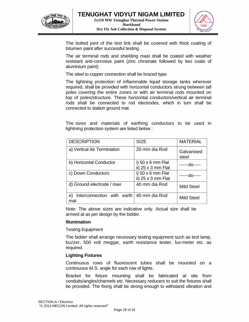
The bolted joint of the test link shall be covered with thick coating of bitumen paint after successful testing. The air terminal rods and shielding mast shall be coated with weather resistant anti-corrosive paint (zinc chromate followed by two coats of aluminium paint). The steel to copper connection shall be brazed type. The lightning protection of inflammable liquid storage tanks wherever required, shall be provided with horizontal conductors strung between tall poles covering the entire zones or with air terminal rods mounted on top of poles/structure. These horizontal conductors/vertical air terminal rods shall be connected to rod electrodes, which in turn shall be connected to station ground mat. The sizes and materials of earthing conductors to be used in lightning protection system are listed below :
DESCRIPTION SIZE MATERIAL
a) Vertical Air Termination 20 mm dia Rod Galvanised steel
b) Horizontal Conductor i) 50 x 6 mm Flat ii) 25 x 3 mm Flat ------do-----
c) Down Conductors i) 50 x 6 mm Flat ii) 25 x 3 mm Flat ------do-----
d) Ground electrode / riser 40 mm dia Rod Mild Steel
e) Interconnection with earth mat
40 mm dia Rod Mild Steel
Note: The above sizes are indicative only. Actual size shall be arrived at as per design by the bidder.
Illumination Testing Equipment The bidder shall arrange necessary testing equipment such as test lamp, buzzer, 500 volt meggar, earth resistance tester, lux-meter etc. as required.
Lighting Fixtures Continuous rows of fluorescent tubes shall be mounted on a continuous M.S. angle for each row of lights. Bracket for fixture mounting shall be fabricated at site from conduits/angles/channels etc. Necessary reducers to suit the fixtures shall be provided. The fixing shall be strong enough to withstand vibration and
TENUGHAT VIDYUT NIGAM LIMITED 2x210 MW Tenughat Thermal Power Station
Jharkhand Dry Fly Ash Collection & Disposal System
SECTION-A / Electrics “© 2014 MECON Limited. All rights reserved”’
Page 29 of 32
high wind velocity. If a roof over platform is available, the fixture can be pendant mounted. The fixtures after erection shall be marked up indelibly with corresponding circuit number for easy identification of lamp circuit.
Street Lighting Poles Erection of Street Lighting poles together with all its accessories including civil foundation work, installing lighting fixture, wiring and cabling work are included within scope of bidder.
Conduit System In case where wiring through conduit is adopted, all conduits shall originate from the respective lighting panel and terminate in lighting fixtures, receptacles etc. Exposed conduits shall be run in straight lines parallel to building columns, beams and walls as far as practicable. Unnecessary bends and crossings shall be avoided to present a neat appearance. Conduit supports shall be provided at an interval of 750 mm for horizontal runs and 1000 mm for vertical runs. Conduits shall be clamped on to approved type spacer plates or brackets by saddles or U-bolts. The spacer plates or brackets in turn, shall be fixed to the building steel by welding and to concrete or brick work by grouting. Wooden plug inserted in the masonry or concrete for conduit support is not acceptable. Embedded conduits shall be securely fixed in position to preclude any movement. In fixing embedded conduit, if welding or brazing is used, extreme care should be taken to avoid any injury to the inner surface of the conduit. Spacing of embedded conduits shall be such as to permit flow of concrete between them and in no case shall be less than 40 mm. Where conduits are run on cable trays they shall be clamped to supporting steel at an interval of 600 mm. For directly embedding in soil, the conduits shall be coated with an asphalt -base compound. Concrete pier or anchor shall be provided where necessary to support the conduit rigidly and to hold it in place. Conduits shall be installed in such a way that trapped condensation is avoided.

TENUGHAT VIDYUT NIGAM LIMITED 2x210 MW Tenughat Thermal Power Station
Jharkhand Dry Fly Ash Collection & Disposal System
SECTION-A / Electrics “© 2014 MECON Limited. All rights reserved”’
Page 30 of 32
Running threads shall be avoided as far as practicable. Where it is unavoidable, check nuts shall be used. Conduits shall be kept, wherever possible, at least 300 mm away from hot pipes, heating device etc. when it is evident that such proximity may impair the service life of cables. Slip joints shall be provided when conduits cross structural expansion joints or where long runs of exposed conduits are installed, so that temperature change will cause no distortion due to expansion or contraction of conduit run. For long run, junction/pull boxes shall be provided at suitable intervals to facilitate wiring. Conduits shall be securely fastened to junction box or cabinets, each with a locknut and insulated bushing inside the box and locknut outside. Conduit lengths shall be joined by screwed couplers. Couplers shall be clearly cut. Conduit joints and connections shall be made thoroughly water-tight and rust-proof by application of a thread compound which will not insulate the joints. White lead is suitable for application on embedded conduit and red lead for exposed conduit. The Battery Room installation shall be made with acid fume proof conduits. Field bends shall have a minimum radius of four (4) times the conduit diameter. All bends shall be free of kinks, indentations or flattened surfaces. etc shall not be applied in making any conduit bend. The entire metallic conduit system, whether embedded or exposed, shall be electrically continuous and thoroughly grounded. Lighting fixture shall not be suspended directly from junction box in the main conduit run. Conduits and fittings shall be properly protected during construction period against mechanical injury. Conduits ends shall be plugged or capped to prevent entry of foreign material. After installation the conduits shall be thoroughly cleaned by compressed air before pulling in the wire. In control rooms and office areas provided with false ceiling conduit run shall be concealed type, embedded in the walls.
Wiring Wiring shall be generally carried out by PVC insulated wires in conduits. All wires in a conduit shall be drawn simultaneously. No subsequent drawing is permissible.

TENUGHAT VIDYUT NIGAM LIMITED 2x210 MW Tenughat Thermal Power Station
Jharkhand Dry Fly Ash Collection & Disposal System
SECTION-A / Electrics “© 2014 MECON Limited. All rights reserved”’
Page 31 of 32
Wire shall not be pulled through more than two equivalent 90º bends in a single conduit run. Wiring shall be spliced only at junction boxes with approved type connections or terminal strips. Maximum two wires can be connected to each way of the terminal block. Splicing of only one phase shall be done in a junction box. For lighting fixtures, connection shall be teed off through suitable round conduit or junction box, so that the connection can be attended without taking down the fixture. For vertical run of wires in conduit, wires shall be suitably supported by means of wooden/hard rubber plugs at each pull/ junction box. A.C. and D.C. circuits shall not be run in the same conduit and junction boxes. Circuits fed from different transformers shall be run through different conduits and Junction boxes. Receptacle circuits shall be kept separate and distinct from lighting and fan circuits. Separate neutral wire shall be provided for each circuit. Wiring throughout the installation shall be such that there is no break in the neutral wire in form of switch or fuse.
Cabling In outdoor areas, main runs from lighting panels shall be directly buried in ground or laid in trenches for the underground portion and through conduit for the over ground portion. Buried cables shall be laid and covered with sand/ riddled earth, and protected from damage by bricks at sides and pre cast concrete stab at top. Buried cables shall have cable markers at 50M interval and projecting 150 mm above ground. At cable bends and joints markers shall be provided. When buried cables cross road, additional protection to be provided in the form of Hume pipe / G.I. pipe.
Grounding All lighting panels, junction boxes, receptacles, fixtures, conduit etc. shall be grounded in compliance with the provision of I.E. Rules.
Painting Street light poles shall be given two coats of aluminium paints after installation. All equipment shall be given touch-up paint as required after installation.
Inspection & Testing

TENUGHAT VIDYUT NIGAM LIMITED 2x210 MW Tenughat Thermal Power Station
Jharkhand Dry Fly Ash Collection & Disposal System
SECTION-A / Electrics “© 2014 MECON Limited. All rights reserved”’
Page 32 of 32
On completion of erection works, the bidder shall request the Engineer for inspection and tests with minimum fourteen (14) days advance notice. The Engineer shall arrange for joint inspection of the installation for completeness and correctness of the work. Any defect pointed out during such inspection shall be promptly rectified by the bidder. The installation shall be then tested and commissioned in presence of the Engineer and put on trial run for stipulated contract period. All rectification, repair or adjustment work found necessary during inspection, testing, commissioning and trial run shall be carried out by the bidder without any extra cost.


![[VIDYUT MODE CMS]cea.nic.in/reports/others/god/gm/procedure_onlinedata_mode.pdf · 2017 Vidyut MODE App for POSOCO Vikiraj Hinger, CruxBytes Consultancy Services V0.2 [VIDYUT MODE](https://static.fdocuments.in/doc/165x107/5f793e27d9e05774002d5086/vidyut-mode-cmsceanicinreportsothersgodgmprocedureonlinedatamodepdf.jpg)