Hydraulic Car Scissor Lift, Scissor Type Car Lift, High Lifting Car Scissor Lift in India

INSTALLATION and OPERATIONMANUALMANUAL
14K SCISSOR LIFT
READ THIS INSTRUCTION MANUAL THOROUGHLY
14K SCISSOR LIFT4814605AF, 4814605AFFM, 4814605LL
READ THIS INSTRUCTION MANUAL THOROUGHLY BEFORE INSTALLING, OPERATING, SERVICING OR
MAINTAINING THE LIFT. SAVE THIS MANUAL.
JUL 2013 REV. - 6-3013309 EXCHANGE AVENUE, CONWAY, ARKANSAS, 72032
TEL: 501-450-1500 FAX: 501-450-1585

2 of 75
TABLE OF CONTENTS
1.0 OWNER / EMPLOYER OBLIGATIONS ......................................................... 4
2.0 IMPORTANT SAFETY INSTRUCTIONS ....................................................... 4
3.0 SAFETY WARNING DECALS ....................................................................... 7
4.0 SPECIFICATIONS ......................................................................................... 8
5.0 CONTENTS .................................................................................................... 9
6.0 TOOLS REQUIRED FOR INSTALLATION OF LIFT ..................................... 9
7.0 INSTALLATION OVERVIEW ....................................................................... 10
8.0 INSTRUCTIONS ........................................................................................... 11 8.1 Flushmount Bay Layout ..................................................................... 12 8.2 Surfacemount Bay Layout ................................................................. 13 8.3 Baseframe Location ........................................................................... 14 8.4 Unpacking the Lift .............................................................................. 15 8.5 Hydraulic Connections ...................................................................... 16 8.6 Air Safety and Auxiliary Air connections ......................................... 18 8.7 Pneumatic Sensor Connections ........................................................ 21 8.8 Electrical Connections ....................................................................... 23 8.9 Initial Operation .................................................................................. 25 8.10 Equalizing Function Check .............................................................. 26 8.11 Maximum Height Adjustment .......................................................... 27 8.12 Level and Support ............................................................................ 28 8.13 Anchoring Procedure ....................................................................... 29 8.14 Grouting Procedure (Optional) ........................................................ 30
9.0 ACCESSORY INSTALLATION .................................................................... 31 9.1 Installation of Line Covers ................................................................. 33
10.0 LOCKING FRONT TURNPLATES & REAR SLIP PLATES (OPTIONAL) 34 10.1 Installation of Front Turnplates ....................................................... 34 10.2 Console Connections for Locking & Lights ................................... 36
11.0 FINAL PROCEDURES ............................................................................... 38 11.1 Check of Assembled Lift .................................................................. 38 10.2 Operation Test with Vehicle ............................................................. 38
12.0 LIFT OPERATION ...................................................................................... 39 12.1 Raising the Lift .................................................................................. 39 12.2 Lowering the Lift ............................................................................... 39
13.0 RECOMMENDED MAINTENANCE ........................................................... 40 13.1 Checking Oil Level for Air Lubricator ............................................. 40 13.2 Maintenance of Turnplate & Slip Plate Locking System (Opt.) ..... 41
14.0 LOCK OUT AND TAG OUT INSTRUCTIONS ........................................... 43 14.1 Isolation and Verification Procedure: ............................................. 44 14.2 Emergency Operation ...................................................................... 45

3 of 75
15.0 TROUBLE SHOOTING .............................................................................. 47
16.0 RECORD OF MAINTENANCE / TRAINING .............................................. 48
17.0 LIFT ASSEMBLY ....................................................................................... 49 17.1 Lift Assembly Parts List ................................................................... 50
18.0 REAR SLIP PLATE TRANSFER BALL ARRANGEMENT ........................ 52
19.0 HYDRAULIC & AIR ASSEMBLY ............................................................... 53 19.1 Line Routing Parts List .................................................................... 55
20.0 HEIGHT LIMIT ASSEMBLY ....................................................................... 56 20.1 HEIGHT LIMIT / LEVELING PARTS LIST ......................................... 56 20.2 EQUALIZE SENSORS PARTS LIST ................................................. 57 20.3 HEIGHT LIMIT / LEVELING PARTS LIST ......................................... 57 20.4 OPTIONAL: LIGHT KIT SENSOR PARTS LIST .............................. 58
21.0 ACCESSORY ASSEMBLY ........................................................................ 59 21.1 Front Turnplate ................................................................................. 59 21.2 Rear Slip Plate Locking Mechanism ............................................... 61 21.3 Airline Routing for Locking Turnplates and Rear Slip Plates ....... 62 21.4 Rear LED Light Assembly: Exploded View .................................... 64
22.0 CONSOLE ASSEMBLY ............................................................................. 66 22.1 Electrical Panel ................................................................................. 66 22.2 Console: Pneumatic & Filtering System ......................................... 67 22.3 Console: Pneumatic & Filtering System -
Locking & Light System (Optional) ................................................. 68 22.4 PNEUMATIC LIMIT SWITCH SCHEMATIC ....................................... 69 22.5 Control Panel .................................................................................... 71 22.6 Console Panel Assembly ................................................................. 72
23.0 POWERPACK ASSEMBLY ....................................................................... 73 23.1 Powerpack Assembly ....................................................................... 73 23.2 Manifold Parts List ........................................................................... 75
4 of 75
1.0 OWNER / EMPLOYER OBLIGATIONS
1. The Owner/Employer shall ensure that lift operators are qualified and that they are trained in the safe use and operation of the lift using the manufacturer’s operating instructions; ALI/SM 93-1, ALI Lifting it Right safety manual; ALI/ST-90 ALI Safety Tips card; ANSI/ALI ALOIM-2008, American National Standard for Automotive Lifts - Safety Requirements for Operation, Inspection and Maintenance; ALI/WL Series, ALI Uniform Warning Label Decals/Placards; and in the case of frame engaging lifts, ALI/LP-GUIDE, Vehicle Lifting Points/Quick Reference Guide for Frame Engaging Lifts.
2. The Owner/Employer shall establish procedures to periodically inspect the lift in accordance with the lift manufacturer’s instructions or ANSI/ALI ALOIM-2008, American National Standard for Automotive Lifts - Safety Requirements for Operation, Inspection and Maintenance; and the Employer shall ensure that the lift inspectors are qualified and that they are adequately trained in the inspection of the lift.
3. The Owner/Employer shall establish procedures to periodically maintain the lift in accordance with the lift manufacturer’s instructions or ANSI/ALI ALOIM-2008, American National Standard for Automotive Lifts - Safety Requirements for Operation, Inspection and Maintenance; and the Employer shall ensure that the lift maintenance personnel are qualified and that they are adequately trained in the maintenance of the lift.
4. The Owner/Employer shall maintain the periodic inspection and maintenance records recommended by the lift manufacturer’s instructions or ANSI/ALI ALOIM-2008, American National Standard for Automotive Lifts - Safety Requirements for Operation, Inspection and Maintenance.
5. The Owner/Employer shall display the lift manufacturer’s operating instructions; ALI/SM 93-1, ALI Lifting it Right safety manual; ALI/ST-90 ALI Safety Tips card; ANSI/ALI ALOIM-2008, American National Standard for Automotive Lifts - Safety Requirements for Operation, Inspection and Maintenance; ALI/WL Series, ALI Uniform Warning Label Decals/Placards; and in the case of frame engaging lifts, ALI/LP-GUIDE, Vehicle Lifting Points/Quick Reference Guide for Frame Engaging Lifts in a conspicuous location in the lift area convenient to the operator.
6. The Owner/Operator shall provide necessary lockout/tagout means for energy sources per ANSI Z244.1-1982 (R1993), Safety Requirements for the Lockout/Tagout of Energy Sources, before beginning any lift repairs and maintenance.
2.0 IMPORTANT SAFETY INSTRUCTIONS
1. When using this lift, basic safety precautions should always be followed, including the following (where applicable):
2. Read all instructions in this manual and on the lift thoroughly before installing, operating, servicing or maintaining the lift.
3. Care must be taken as burns can occur from touching hot parts.
4. Do not operate equipment with a damaged cord or if the equipment has been dropped or damaged – until it has been examined by a qualified service person.
5. Do not let a cord hang over the edge of the table, bench, or counter or come in contact with hot manifolds or moving fan blades.

5 of 75
6. If an extension cord is necessary, a cord with a current rating equal to or more than that of the equipment should be used. Cords rated for less current than the equipment may overheat. Care should be taken to arrange the cord so that it will not be tripped over or pulled.
7. Always unplug equipment from electrical outlet when not in use. Never use the cord to pull the plug from the outlet. Grasp plug and pull to disconnect.
8. Let equipment cool completely before putting away. Loop cord loosely around equipment when storing.
9. To reduce the risk of fire, do not operate equipment in the vicinity of open containers of flammable liquids (gasoline).
10. Adequate ventilation should be provided when working on operating internal combustion engines.
11. Keep hair, loose clothing, fingers, and all parts of body away from moving parts.
12. To reduce the risk of electric shock, do not use on wet surfaces or expose to rain.
13. Use only as described in this manual. Use only manufacturer’s recommended attachments.
14. ALWAYS WEAR SAFETY GLASSES. Everyday eyeglasses only have impact resistant lenses, they are not safety glasses.
15. Inspect lift daily. Do not operate if it malfunctions or problems have been encountered.
16. Never attempt to overload the lift. The manufacturer’s rated capacity is shown on the identification label on the power side column. Do not override the operating controls or the warranty will be void.
17. Before driving vehicle between the towers, position the arms to the drive-through position to ensure unobstructed clearance. Do not hit or run over arms as this could damage the lift and/or vehicle.
18. Only trained and authorized personnel should operate the lift. Do not allow customers or bystanders to operate the lift or be in the lift area.
19. Position the lift support pads to contact the vehicle manufacturers recommended lifting points. Raise the lift until the pads contact the vehicle. Check pads for secure contact with the vehicle. Check all arm restraints and insure they are properly engaged. Raise the lift to the desired working height.
20. Some pickup trucks may require an optional truck adapter to clear running boards or other accessories.
21. NOTE: Always use all 4 arms to raise and support vehicle.
22. Caution! Never work under the lift unless the mechanical safety locks are engaged.
23. Note that the removal or installation of some vehicle parts may cause a critical load shift in the center of gravity and may cause the vehicle to become unstable. Refer to the vehicle manufacturer’s service manual for recommended procedures.
24. Always keep the lift area free of obstruction and debris. Grease and oil spills should always be cleaned up immediately.
25. Never raise vehicle with passengers inside.
26. Before lowering check area for any obstructions.
27. Before removing the vehicle from the lift area, position the arms to the drive-thru position to prevent damage to the lift and /or vehicle.
28. Do not remove hydraulic fittings while under pressure.

6 of 75
For additional safety instructions regarding lifting, lift types, warning labels, preparing to lift, vehicle spotting, vehicle lifting, maintaining load stability, emergency procedures, vehicle lowering, lift limitations, lift maintenance, good shop practices, installation, operator training and owner/employer responsibilities, please refer to “Lifting It Right” (ALI/SM) and “Safety Tips” (ALI/ST) and vehicle lift points for service garage lifting SAE J2184.
For additional instruction on general requirements for lift operation, please refer to “Automotive Lift-Safety Requirements For Operation, Inspection and Maintenance” (ANSI/ALI ALOIM).
Installation shall be performed in accordance with ANSO/ALI ALIS, Safety Requirements for Installation and Service of Automotive Lifts.
ATTENTION! This lift is intended for indoor installation only. It is prohibited to install this product outdoors. Operating environment temperature range should be 41 – 104 °F (5 – 40 °C). Failure to adhere will result in decertification, loss of warranty, and possible damage to the equipment.
SAVE THESE INSTRUCTIONS Note: Some images in this manual are generic and may not ressemble the lift you have purchased.

7 of 75
3.0 SAFETY WARNING DECALS

8 of 75
4.0 SPECIFICATIONS
Maximum Capacity: 14 000 lbs 6363 kg
Overall Width (min-max): 92½” – 94½” Inches 2350-2400 mm
Overall Length: 270 Inches 6858 mm
Maximum Raised Height: 72 Inches 1829 mm
Minimum Lowered Height: 10 Inches 254 mm
Runway Width 26 Inches 660 mm
Maximum Wheelbase: 176 Inches 4470 mm
Lifting Time (approx.): 75 - 85 Seconds: depending on load
Power Ratings: 230V, 1 Ph, 60Hz, 20A
Maximum Operating Pressure @ Rated Load:
4600 PSI
Air Supply requirements: 90 to 120 PSI
Pneumatic Filtration Oil Type: Snap-On #IM6 or Equivalent
Hydraulic Oil Capacity: Tank size: 4.0 gal Lift capacity: 6.0 gal
Hydraulic Oil Type: ISO 32 (10 weight) hydraulic oil
Shipping Weight: 4870 lbs 2209 kg
Figure 1 - Lift Dimensions

9 of 75
5.0 CONTENTS
The complete lift is contained in two (2) packages: 1. The main structural components are pre-assembled and packaged on top of each other. 2. The remaining parts are packed in a console/accessory box. Refer to the packing slip inside the
accessory box for a list contents. Components include: 1pc. – Left Side Main Frame Assembly: Runway, Scissors and Base Frame 1pc. – Right Side Main Frame Assembly: Runway, Scissors and Base Frame 1pc. – Console and Accessory box. (See accessory box list for contents) 1pc. – Grout container 1pc. – Customer care kit including manuals
6.0 TOOLS REQUIRED FOR INSTALLATION OF LIFT
Hammer Drill or similar, 1/4” and 1/2” Concrete Drill Bits 4’ Level SAE Wrenches and Sockets Hammer Pry Bar – 5’ Long Chalk Line Tape Measure Side Cutters Screw Drivers Funnel Utility Knife Torque Wrench
Recommended:
Laser Leveler Plumb Bob Impact Gun Boom and/or Engine Hoist 8’ Sling Engine Crane
Note: Apply LOCTITE #242 on required fasteners where symbol is shown.
If fasteners are removed reapply LOCTITE before re-installing.

10 of 75
7.0 INSTALLATION OVERVIEW This is the order in which this installation is to take place:
1. Layout the Bay
2. Unpacking the Lift
3. Inspect the Lift
4. Connect Hydraulic Lines
5. Connect Air Lines
6. Connect Pneumatic Sensors
7. Connect Electrical
8. Initial Run of Lift
9. Level, Shim and Anchor
10. Install Accessories
11. Locking Front Turnplates and Rear Slip Plates / Light System (Optional)
12. Final Check
13. Clean
14. Train Customer on Operation of the Lift
IMPORTANT: Shop air must be connected to the inlet port at the FRL unit on the console, in order for lift to operate.
11 of 75
8.0 INSTRUCTIONS When the lift arrives on site please read the owner’s installation and operation manual completely. Check the contents to make sure no parts are missing before starting installation. Gather all of the tools listed and make sure that the instructions are fully understood before commencing with the installation. IMPORTANT: It is the user’s responsibility to provide a satisfactory installation area for the lift. Lifts
should only be installed on level concrete floors with a minimum thickness of six inches (6") or 152 mm. Concrete must have a minimum strength of 4000 psi or 28 MPa and should be aged thirty (30) days prior to installation. Please consult the architect, contractor or engineer if doubt exists as to the strength and feasibility of the floor to enable proper lift installation
and operation. A qualified person should be consulted to address seismic loads and other local or state requirements. It is the user’s responsibility to provide all wiring for electrical hook-up prior to installation and to insure that the electrical installation conforms to local building codes. Where required, it is the user’s responsibility to provide an electrical isolation switch located in close proximity to the lift that will enable emergency stop capability and isolate electrical power from the lift for any servicing requirements.

12 of 75
8.1 Flushmount Bay Layout
NOTE: Leave any additional room for any desired aisle or work area. Recommended clearance around the lift is a minimum of three (3) feet. Ensure clearance conforms to local building and fire codes. Recommended overhead clearance is a minimum of twelve (12) foot ceiling providing 6 feet for the maximum lift height and 6 feet for the supported vehicle. For vehicles taller than 6 feet it is recommended that the user provides additional overhead clearance or a shut off mechanism to stop the lift from raising the vehicle too high. Please contact customer service for latest installation diagram as it may change without notice.
Figure 2 - Typical Bay Layout (Flush Mount)

13 of 75
8.2 Surfacemount Bay Layout
NOTE: Leave any additional room for any desired aisle or work area. Recommended clearance around the lift is a minimum of three (3) feet. Ensure clearance conforms to local building and fire codes. Recommended overhead clearance is a minimum of twelve (12) foot ceiling providing 6 feet for the maximum lift height and 6 feet for the supported vehicle. For vehicles taller than 6 feet it is recommended that the user provides additional overhead clearance or a shut off mechanism to stop the lift from raising the vehicle too high. Please contact customer service for latest installation diagram as it may change without notice.
Figure 3 - Typical Bay Layout (Surface Mount)

14 of 75
8.3 Baseframe Location
IMPORTANT: DO NOT CUT THE SHIPPING STRAPS HOLDING EACH SCISSOR ASSEMBLY TOGETHER UNTIL INSTRUCTED TO DO SO.
1. With reference to Figure 3, the installer should locate the most suitable location in the shop for the lift.
2. Snap a chalk line for the centerline
of the lift ensuring that it matches the centerline of the bay door.
3. Measure and snap two (2) parallel
chalk lines on either side the centerline for the inside edges of the baseframes. Refer to Figure 4 for the dimensions necessary to provide the desired width between the two runways. A distance of 36" (914mm) between the baseframes will provide the standard width of 38” between the inside of the runways.
4. Measure and snap a chalk line
parallel to the shop door for the front of the baseframes, a minimum distance of 249 1/8” (6329mm) is recommended.
5. Before proceeding, ensure that
once the runways are installed adequate workspace will remain in front of the lift. Refer to the minimum requirements listed in the installation and operation manual of any alignment equipment as needed.
Figure 4 – Baseframe Locations
Refer to the minimum requirements listed in the installation and operation manual of any alignment equipment as needed.

15 of 75
8.4 Unpacking the Lift
1. Unpack the console and place it in the desired location at the rear of the lift. The console can be placed on either the left or right hand side of the lift.
2. Unpack the runways and lay each baseframe along the chalk lines.
Do not remove the individual strapping on the runways until they have been positioned on the chalk lines.
3. Position the baseframes on chalk lines, and ensure that the runways are parallel. Ensure that both
the inside dimensions (front and back) of the baseframes as well as the diagonal distances are equal.
4. Remove the remaining packing straps, and remove the hydraulic hoses, polytubes and proximity
switch wires from under the deck. Hoses and wiring are located under the rear portion of the deck and are factory pre-installed.
5. Inspect lift for damage or any irregularities. If any are found, please contact customer service
before proceeding. Note: Do not pull excessively on the hoses and wiring as it may strain the connections to the baseframe.
Chalk Line
Center Line
Front
Rear
Turnplate
Jackbeam Rail
Ensure that the turnplate pockets are at the front, and that Jack Beam rails for each runway face each other.

16 of 75
8.5 Hydraulic Connections 1. Open the front and rear access covers of the console. 2. Unravel all hoses, air lines, and sensor cables from each runway and connect the hydraulic lines
as shown in Figure 5. Save the caps from the hydraulic lines for capping other fittings mentioned in the next step.
Always make sure that the connections are clean to avoid contaminating the
hydraulic system. Do not kink hydraulic hoses or air lines. Do not remove hydraulic fittings while under pressure
3. The primary supply lines and equalizing lines from each runway are:
Left Side (L): Right Side (R): CL CR EQL + 22718 EQR + 22719 (“C” for “Cylinder” and “EQ” for “Equalize”)
4. The 3/8” polytube return lines in the baseframes should be joined inside the console using a 3/8”
“T” connector (Figure 5) from the hardware kit. To connect the “T” connector to the tank, cut off approximately 6” to 8” (152.4mm to 203.2mm) from either polytube supplied. Next, connect the other end of the tube to the pump connection marked T (Tank) (Figure 6)
Figure 5 - "T" Connector
Approx. 6” to 8” (152.4mm to 203.2mm), cut from any of the two polytubes supplied
Polytube supplied in the accessory box

17 of 75
Figure 6 - Hydraulic Connections

18 of 75
8.6 Air Safety and Auxiliary Air connections
WARNING! WEAR SAFETY GOGGLES AND PRACTICE CAUTION WHILE WORKING WITH COMPRESSED AIR.
1. Uncoil the ¼” polytube under each deck that is connected to the air release cylinder. Route this
line to the ‘y’ connector in the console.
2. Locate the FRL. The hardware is preassembled on the FRL, remove the two nuts ensuring the screws do not fall.
3. Assemble the FRL unit to the side of the console with the hardware provided on the FRL unit. Orient with supply port to the rear of the console and 90 fitting lined up with the hole in the side of the console.
4. On the inside of the console, assemble the nuts but leave loose, engaging 2 threads.
5. Rotate the FRL such that the 90 fitting passes through the hole. Secure the T-fitting inside the console to the 90 fitting with a wrench.
6. Tighten the nuts to secure the FRL
7. The 3/8” polytube for the auxiliary air connections is coiled under the right side runway. Route this
hose to the console and connect it to the tee fitting inside the console. 8. A 3/8” NPT fitting (not supplied), is needed to connect shop air supply to the Air Filter / Regulator/
Lubricator Unit. Connect air line to the FRL unit located on the outside of the console. IMPORTANT: Shop air must be connected to the inlet port at the FRL unit on the console, in order for lift to operate.
Customer to supply 3/8” connector for airline
Attach FRL unit to the side of the console with hardware provided
Union “Y” for 1/4” polytube
Secure the T-fitting to the 90○ fitting on the FRL unit (3/8” air connection

19 of 75
WARNING! REPLENISH THE LUBRICANT AFTER RELEASING THE INLET PRESSURE. LUBRICATION CANNOT TAKE PLACE UNDER A PRESSURIZED CONDITION
9. Unscrew the lubricator bowl by turning it in a counter-clockwise direction 10. Fill the Lubricator Reservoir with Snap-On Air Motor Oil #IM6 or Equivalent. Oil supply to the
lubricator should be less than the upper limit of the oil level
The console is equipped with an Air Filter / Lubricator / Regulator to ensure a clean air supply is provided to the safety release cylinders, jackbeams, and any other air tools connected to the lift. The Air Regulator should be set between 90-120 psi.
IMPORTANT! OIL OTHER THAN ABOVE MAY CAUSE DAMAGE AND DRIPPING FAILURE
11. Screw in the lubricator bowl
12. Slowly pressurize the system
Note: The regulator has been set to operate at 90PSI
Note: The sight dome assembly has already been set to provide 3-5 drips per minute. Check the sight dome assembly and verify that oil drips.
13. Check the air system for any leaks.
Lubricator Bowl
Sight Dome Assembly

20 of 75
Figure 7 - Air Safety & Auxiliary Air Connections

21 of 75
8.7 Pneumatic Sensor Connections There are three (3) pneumatic limit switches on this lift. Each runway is outfitted with an individual equalizing pneumatic switch mounted on a bracket located under the front of the runway. The third pneumatic switch, used for upper limit detection, is located under the rear slip plate area on the left scissor assembly. Each Pneumatic Switch has a supply line and return line.
1. The equalizing pneumatic switch and upper limit pneumatic switch on the left side scissor assembly are supplied by the 3/8” jackbeam air line (Figure 8).
2. The equalizing pneumatic switch on the right side deck assembly is supplied by the main air supply in the console. Connect the supply line labeled “EQ. SUPPLY” as shown in Figure 9.
Figure 8a - Equalizing Pneumatic Switch. (View under LS Deck - Front)
Figure 8b - Upper Limit Pneumatic Switch. (View under LS Deck - Rear)

22 of 75
Figure 9 – Right Side Equalizing Limit Pneumatic Switch (Console)
3. The two (2) equalizing pneumatic switch return lines, labeled “EQ. RETURN”, are connected
to a union ‘Y’ fitting in the console (Figure 10). 4. The upper limit pneumatic switch return line, labeled “LMT RETURN”, is connected to the
pressure switch fitting in the console (Figure 10).
Figure 10 – Pneumatic Switch Return Line Connections (Console)

23 of 75
8.8 Electrical Connections
Figure 11a - Console Circuit Connections
** Optional for locking and lights. See next page for electrical diagram of LED driver box.
NOTE: Overload fuse does not come with single phase power unit NOTE: Optional Voltage and Phase power units will include separate wiring diagrams.
DANGER ! – Ensure that electrical connections are completed by a licensed electrician. Electrical shocks can cause serious injury or even death.

24 of 75
Figure 11b - **Optional: LED Driver Box Circuit Connections

25 of 75
8.9 Initial Operation 1. Add hydraulic fluid to reservoir (ISO 32 10wt). Oil capacity for the lift is approximately 6 gallons.
IMPORTANT: Shop air must be connected to the inlet port at the FRL unit in the console, in order for lift to operate.
2. Raise lift to 2 ft, lower and repeat 3 to 4 times, using “UP” and “DOWN” controls on the front of the console.
* During this stage the lift is not yet full of oil. During the following steps, one side of the lift may raise higher than the other. 3. Using the “BYPASS” button inside the console, start raising the lift to the last lock position as
shown in Figure 12.
Monitor the fluid level during this procedure. At approximately half way, add 10 liters of oil to the reservoir. Continue to raise the lift.
NOTE: Ensure the gauges inside the console are monitored and pressure does not reach 1000 psi. If 1000 psi is reached, lower the lift onto the locks to relieve the pressure. Continue to raise the lift until both sides of the lift are on the last lock position. (Figure 12)
IMPORTANT: The unit must be on the last locking position to bleed the lift.
Figure 12-Safety lock position for bleeding. Figure 13- Location of bypass button.
4. BLEED THE SYSTEM: Once the lift is placed on the last safety position, remove the polytube
return lines, at the tee fitting (Figure 5) and place them into a funnel over the reservoir. Press the bypass button until a clear stream of oil is flowing from the return lines. Release the bypass button and wait for 5 -10 seconds and continue to bleed. Repeat this “wait and bleed” procedure 5 times or until air is no longer visible in the return lines. Connect polytube lines back to the tee fitting.
5. RELEASE THE SAFETY LOCKS: Place a rag or drip pan directly under the secondary cylinder and remove the 90 deg. push lock fittings on the top of the secondary cylinders (see Figure 14). Cap the port using the plugs provided.
6. Holding the air safety release button on the console, raise the lift using the “BYPASS” button until
the safety locks disengage. DO NOT BUILD PRESSURE OVER 1000 PSI. 7. Lower the lift to the next safety lock. Remove the plugs and reinstall the 90 deg push lock fittings.
Lower the lift to a comfortable working height and continue the installation.
Bypass button

26 of 75
Figure 14- Remove fitting. Figure 15- Cap port using plug provided.
8.10 Equalizing Function Check Check: To verify that the pneumatic switches are functioning, remove the rear panel on the console and locate the five (5) Din Connector/Solenoid assemblies; (four (4) on manifold block and one (1) on the pump). When the lift reaches its fully lowered position, these din connectors will emit a red light for 3 to 5 seconds. If this does not occur, check the pneumatic connections at the sensors and at the console.
PLUG

27 of 75
8.11 Maximum Height Adjustment The lift has been pre-adjusted at the factory to a 72” working height. If a lower height limit is required, the system can be adjusted to a minimum of 43”. 1. Raise lift to full height by pressing the up button (do not press the by-pass button). 2. The limit switch (see Figure 16) should automatically stop the lift once the 72” working height
(bottom of baseframe to top of runway) is reached.
3. Lower the lift to the desired working height ensuring the safety locks can be disengaged.
4. Loosen the 1/4” adjustment bolts and slide the limit switch and bracket assembly towards the scissor cross-tube until the roller lever on the switch is fully depressed. NOTE: Switch must be installed in front of the cross-tube. Hold in place and tighten ¼” bolts.
CHECK: Lower the lift to the ground, then raise until the lift stops. Perform this function a few times to verify the upper limit is set correctly. NOTE: Make sure locks can be disengaged at the maximum or desired height.
UPPER LIMIT PNEUMATIC SWITCH
LOCATION: Underside of Driver Runway.
Figure 16 - Upper limit proximity sensor
NOTICE
The limit switch should never allow the working height to be above 72”. If the automatic stop height is above 72”, damage or failure of the hydraulic seals in the cylinder can occur.

28 of 75
8.12 Level and Support
NOTICE - CORRECT LEVELING IS IMPORTANT TO ENSURE THE PROPER
OPERATION OF THE LIFT. TAKE PRECAUTIONS TO ENSURE ACCURATE LEVEL READINGS WHEN PERFORMING THIS PROCEDURE
Side-to-side leveling measurements should be taken off the baseframe, and measurements should be taken on each baseframe as well as between the two baseframes. Front-to-back level measurements should be taken on the runways.
1. Press the up button and raise the lift to the fully extended operating position. Check the location of the baseframes compared to Figure 4, and make minor adjustments as required.
2. Level the baseframes using the 5/8” leveling bolts provided at each of the four (4) corners. 3. Use shims provided to support under glide block area of baseframe and under front hinges.
See Figure 17.
Figure 17 - Shimming

29 of 75
4. Verify that the baseframes are level side-to-side and that the runways are level front-to-back. The front turnplate and rear slip plate are the areas of interest. Check that the spacing between the runways is as desired, and that this spacing is equal at both the front and rear of the lift. Check that the diagonal measurements between opposite corners of the baseframes are equal. Lower and raise the lift and repeat these measurements.
5. Adjust the 3/4" support bolts on the four (4) corners of the baseframes to level the runway at
fully collapsed position. 6. Once lift is level, back off 5/8” leveling bolts so that the base is firmly sitting on the shims. Re-
check to make sure the lift is still level and shims are holding properly. Note: These bolts must be removed once the shims are installed under the base correctly (same as the center bolt on the base).
8.13 Anchoring Procedure
CAUTION! WEAR SAFETY GOGGLES AND PRACTICE CAUTION WHILE DRILLING CONCRETE.
Figure 18 – Anchoring
1. Lower the lift and measure the distance between the Jackbeam rails at front and rear of the lift. 2. Raise the lift to full height and repeat the measurements, and ensure there are no differences. 3. Using a rotary hammer drill and a 1/2” concrete bit, drill through the floor at each of the four (4)
anchor bolt locations on each of the base frames. Refer to Figure 18. 4. Assemble the nut and washer onto the 1/2” x 4 1/2” long wedge anchor bolts supplied. A
minimum of six threads must be visible below the surface of the nut. 5. Clean out the drilling dust from the holes and hammer in the anchors until they make contact
with the baseplate. Hand tighten all anchor bolts. 6. Torque all anchor bolts to 40 ft-lbs. 7. Position the console in the final desired location. Using a rotary hammer drill and a 1/4”
concrete bit, drill and anchor the console to the floor using the Nail in Anchors located in the hardware kit.
8. Use the line covers to protect all cables, hoses, and wiring running to the lift. Using a rotary
hammer drill and a ¼” concrete bit, drill and anchor the line covers using the nail in anchors located in the hardware kit.
If anchor bolts do not tighten to 40 ft-lbs. OR project more than 2 ¼” above the concrete surface, the concrete should be replaced by an appropriate concrete pad.

30 of 75
8.14 Grouting Procedure (Optional) 1. Pour grouting under the load area of each base frame as shown in Figure 19. Ensure that grout
is evenly distributed under the frame and finish the edges with a 45 degree chamfer. Refer to specific grouting instructions on the package. Leave a drain area to allow any liquids to escape.
2. GROUTING MUST FULLY CURE BEFORE PROCEEDING. Do not operate the lift while grout is curing. Refer to instructions on the package for recommended cure times. [Non-Shrink Grout (3000psi min. in 24hrs, 7000psi min. in 30 days)]
Figure 19 - Grouting Locations

31 of 75
9.0 ACCESSORY INSTALLATION 1. Install the front runway stops located in the accessory box using the ½” hex bolts, washers, lock
washers, and hex nuts located in the hardware kit.
The runway stops are designed as a secondary means to restrain a vehicle from inadvertently rolling off the runways. Property damage and physical injuries may occur if this warning is not adhered to.
2. Install the mounting bracket and then the rear approach ramps using the Approach Ramp Pins
located in the accessory box, and the hex head bolts, flat washers, lock washers, hex nuts and cotter pins located in the hardware kit.
3. Install Jackbeams with reference to the Jackbeam user manual.
Hex Bolt Flat Washer Lock Washer
Hex Nut

32 of 75
4. Position the moveable workstep in the desired location. There are slots along the span of each
runway where the workstep can be mounted. When not in use, the workstep can be stored under the front section of the runway.
WARNING!! ENSURE THE WORKSTEP IS FULLY ENGAGED PRIOR TO USE. IF MORE THAN
ONE WORKSTEP IS IN USE, DO NOT TRY TO STEP ACROSS OR JUMP FROM ONE STEP TO ANOTHER. NEVER USE THE WORKSTEP WHILE THE LIFT IS IN OPERATION. SERIOUS INJURY COULD RESULT FROM IMPROPER USAGE OF THE WORKSTEPS.
WARNING! WORKSTEP MAXIMUM CAPACITY IS 250 LBS.
WARNING! FOR FLUSHMOUNT INSTALLATIONS ENSURE WORKSTEP IS REMOVED BEFORE RAISING OR LOWERING THE LIFT.

33 of 75
9.1 Installation of Line Covers
1. Install line covers once console is installed and hydraulic lines are routed.
2. Position line cover “C” behind the right baseframe as shown. 3. Cut 11-3/8” off length of line cover “B” and position it behind the left baseframe as shown. Do
not discard the cut piece as it will be used in step 4. Note: It is important to create square cuts. The use of a sliding miter saw or a simple miter box is recommended.
4. Position the line covers “A” between line cover “C” & “B” and mark where they overlap. Cut
each to fit. 5. Using the remaining piece of Line cover “B” from step 2, place as shown below. 6. Position line covers “D” to the console. Cut if required. 7. The number along each side of the line covers represents the quantity of fasteners required to
secure them in place. Using a 1/4” concrete drill bit, drill holes as required and install the supplied 1/4” x 1” long nail in anchors (6-0141).
Note: Tapcon or equivalent concrete screws can be used as an option for future removal.
Optional: To locate the consoles on left side of lift, the setup is mirrored with the following changes to the above installation steps:
Step 3 – use line cover A instead of B. Step 4 – use (2) of line cover B. Step 5 – use remainder of line cover A from step 3.
Note: If baseframe is shimmed to a point where the line cover does not sit flush due to interference with hoses, the line cover can be heated with a heat gun and then placed over the hoses for a cleaner look.

34 of 75
10.0 LOCKING FRONT TURNPLATES & REAR SLIP PLATES (OPTIONAL)
10.1 Installation of Front Turnplates
Avoid inserting fingers in the front alignment pan cut-out, if position of the turnplate assembly exposes such openings. Ensure that air supply to the lift is turned off and no person is operating on the console during maintenance of clamping elements of the locking system.
During normal use, the front turnplates and rear slip plates may move rapidly, when locking system is activated. This creates pinch points for your fingers or hands. Keep hands clear of these pinch points when lift air supply is connected. No person shall operate console while maintenance or inspection of the slip plates is in process.
1. Lower lift to a comfort height. 2. Place each front turnplate assembly, one by one, on the front alignment pan on runway. Moving
handles of the turnplates should be oriented to the outside of lift, shown below.

35 of 75
Ensure that the locking system components on the bottom of the turnplate (air cylinder, fittings, and plastic clamping parts) are not hit against the runway during placement. 3. Verify that the turnplate assembly is completely seated in the front alignment pan. Gently slide
each turnplate in the alignment pan, left and right, to verify that they can be positioned for different car widths. Do not hit plastic locking ring forcefully against the edges of the cut-out in the front alignment pan.
4. Connect free ends of front air lines to the turnplate locking cylinder: blue air line to the cylinder
port marked with a blue dot and red air line to the cylinder port marked with a red dot [Figure shown below].
5. Plug the electrical connector on the turnplate light cord into the electrical connector on the cable
at the front.
*Note: Objects in pictures may not be exactly as shown.

36 of 75
10.2 Console Connections for Locking & Lights
Locking & Light System
1. Connect the (2) red & blue polytubes from lift to corresponding “y” fitting in the console (see Detail C).
2. Connect the 4mm polytube labeled “Return” to pushlock fitting on the LED driver box.
Connect the other 4mm polytube labeled “Supply” to the pushlock “Tee” w/ reducer (see Detail “A”)
3. Connect the red & blue electrical connectors from lift to corresponding red & blue electrical
connectors from the LED driver box (see Detail B).

37 of 75
4. Once all connections are made, test system as follows:
a. Light System – Lift must be fully collapsed. Start raising lift. At approximately 30” from the ground, the lights will illuminate. If not, please check that the 4mm polytube connections are correct as they may be reversed. Comparable to the Upper Limit System (see Section 7.7), the Light kit is turned on by a similar method. This system will have its own Cam and Sensor, located on the upper hinge at the front right side runway. NOTE: Unlike the Upper Limit System, this system is not adjustable and is factory set.
b. Locking System – On front of console, switch the Slip Plate lever to “Unlock”. All
locking plates should be free to move, please verify. Now switch the lever to “Lock”, all locking plates should be centered and locked, please verify. If not, check that all polytube connections are correct and there is 90-120 psi of air pressure.
38 of 75
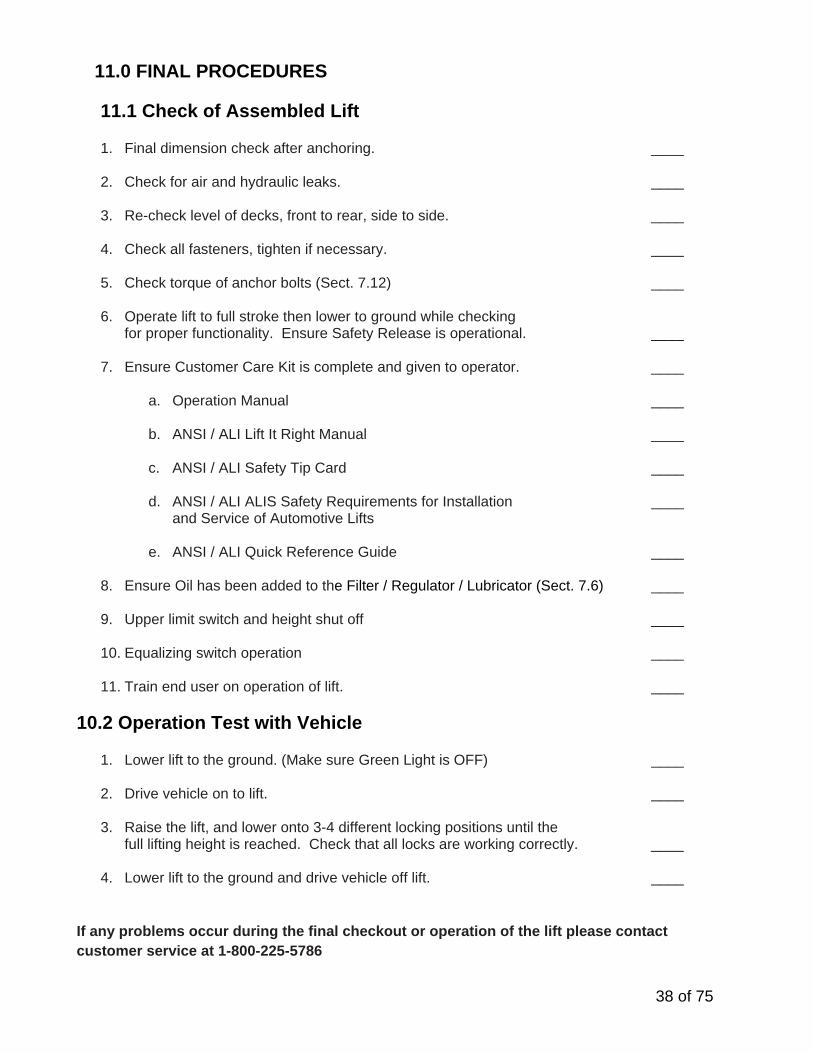
11.0 FINAL PROCEDURES
11.1 Check of Assembled Lift
1. Final dimension check after anchoring. ____
2. Check for air and hydraulic leaks. ____
3. Re-check level of decks, front to rear, side to side. ____
4. Check all fasteners, tighten if necessary. ____
5. Check torque of anchor bolts (Sect. 7.12) ____
6. Operate lift to full stroke then lower to ground while checking for proper functionality. Ensure Safety Release is operational. ____
7. Ensure Customer Care Kit is complete and given to operator. ____
a. Operation Manual ____
b. ANSI / ALI Lift It Right Manual ____
c. ANSI / ALI Safety Tip Card ____
d. ANSI / ALI ALIS Safety Requirements for Installation ____ and Service of Automotive Lifts
e. ANSI / ALI Quick Reference Guide ____
8. Ensure Oil has been added to the Filter / Regulator / Lubricator (Sect. 7.6) ____
9. Upper limit switch and height shut off ____
10. Equalizing switch operation ____
11. Train end user on operation of lift. ____
10.2 Operation Test with Vehicle
1. Lower lift to the ground. (Make sure Green Light is OFF) ____
2. Drive vehicle on to lift. ____
3. Raise the lift, and lower onto 3-4 different locking positions until the full lifting height is reached. Check that all locks are working correctly. ____
4. Lower lift to the ground and drive vehicle off lift. ____
If any problems occur during the final checkout or operation of the lift please contact customer service at 1-800-225-5786

39 of 75
12.0 LIFT OPERATION
12.1 Raising the Lift
1. If the lift is equipped with sliding Jack Beam(s), be sure that the Beam(s) are positioned at the front or mid travel of the lift, fully down, and with the risers removed and stored. Never store Jack Beams at the rear of the lift.
2. Ensure that the lift is fully lowered before attempting to load or unload a vehicle. 3. Ensure that locking pins are in the front turnplates and rear slip plates before driving a vehicle
onto the lift. 4. Position the vehicle on the lift ensuring the resulting load on the deck is distributed as evenly
as possible. Under no circumstances should a vehicle be lifted if the weight distribution is unbalanced by more than 10% on either side. Maximum wheelbase for this lift is 176”.
ATTENTION: THE VEHICLE IS POSITIONED CORRECTLY WHEN THE DISTANCE FROM THE CENTER OF THE TIRES TO THE INSIDE EDGE IF THE RUNWAYS IS EQUAL ON BOTH RUNWAYS, FOR BOTH THE FRONT AND REAR TIRES. 5. Chock the vehicle using the wheel chocks provided. 6. Check that there are no obstructions above the lift that could damage the lift or vehicles. 7. Raise the lift by pressing the up button on the control console. Raise the lift past the desired
working height until both mechanical safeties are heard engaging. Press the down button to lower the lift down onto both of the mechanical safeties
8. Do not raise or lower the lift with the vehicle on the Jack Beam.
WARNING! NEVER WORK UNDER A VEHICLE OR THE LIFT UNLESS IT IS POSITIONED ON BOTH MECHANICAL SAFETIES!
______________________________________________________________________________
12.2 Lowering the Lift
1. Check that there are no obstructions under the lift or vehicle. Be sure that the sliding Jack Beams are fully lowered and positioned at the front or mid section of the lift.
2. Raise the lift by pressing the up button until both runways are clear of their mechanical safety
locks. 3. Press the air safety release button to release the mechanical safeties. 4. While holding the air safety release button, press the down button and lower the lift to the
completely collapsed position. 5. Remove wheel chocks and ensure that locking pins are in the front turnplates and rear slip
plates before driving a vehicle off the lift. 6. Be certain that the lift is completely lowered before removing the vehicle from the lift.
7. Do not raise or lower the lift with the vehicle on the Jack Beam.
ATTENTION: THE OPERATOR MUST ALWAYS KEEP THEIR ATTENTION ON THE OPERATION OF THE LIFT WHILE RAISING OR LOWERING. IF AN OBSTRUCTION IS SEEN, RELEASE BOTH THE AIR SAFETY RELEASE BUTTON
AND THE DOWN BUTTON TO STOP THE LIFT.

40 of 75
13.0 RECOMMENDED MAINTENANCE The following maintenance schedule is recommended for ensuring the operation of the lift. A record of maintenance performed should be maintained and any items that resulted in additional service should be noted.
Schedule Maintenance Required Check that the upper and lower glide tracks are clean and free of
debris. This area should be checked before raising or lowering the lift.
Inspect the operation of the lift by raising and lowering the lift fully. Daily Check for the proper engagement and release of mechanical safety
locks. If bolts are removed for maintenance re-apply LOCTITE #242 before re-assembly
Check hydraulic lines for leaks and fraying. Frayed hoses must be replaced immediately.
Weekly
Check the fluid level in the reservoir with the lift fully lowered. Top up reservoir with ISO 32 (10 weight) hydraulic oil as needed.
Check Oil Level in Air Line Lubricator and refill if required (See 11.2) Check anchor bolts for tightness. Torque to 40 ft-lbs if needed.
Monthly Inspect the electrical and mechanical operation of all switches. Inspect runway stop fasteners monthly.
5 Year Change the hydraulic fluid every five years. Use only ISO 32
(10 weight) hydraulic oil. NOTE: FAILURE TO FOLLOW RECOMMENDATION MAY AFFECT WARRANY OF LIFT
13.1 Checking Oil Level for Air Lubricator The Air Lubricator is located on the outside of the console to allow for easy monitoring of the oil level. If oil level is low, refill the lubricator bowl using one of the following methods: Method 1 – Can be done under pressure.
1. Unscrew the lubrication plug assembly 2. Refill the bowl using Snap-On Air Oil #IM6 or equivalent 3. Screw in the lubrication plug assembly 4. Check the number of oil drops again.
This does not usually need to be adjusted Method 2 – Cannot be done under pressure
1. Release inlet pressure from system 2. Unscrew lubricator bowl 3. Fill the lubricator bowl using Snap-On Air Oil #IM-6 4. Screw in lubricator bowl 5. Slowly pressurize system 6. Check the number of oil drops again.
This does not usually need to be adjusted
Lubricator Bowl
Lubrication Plug Assembly
NOTE: Failure to maintain oil level in lubricator will void warranty on all pneumatic components.

41 of 75
13.2 Maintenance of Turnplate & Slip Plate Locking System (Opt.)
1. Observe locking mechanisms with every lift rise for air line connection integrity. Also ensure that
no foreign objects are trapped in the clamping components. 2. Once a week inspect the mating conical surfaces of the front turn table locking mechanism. If
necessary, blow with compressed air or wipe with a clean cloth any road dust, salt or other contaminants, including liquids. Greasing of these surfaces is not required and not recommended.
3. After extended use, it may be required that some components of the front turnplate will need
replacement, due to normal wear. Please ensure to re-apply Loctite where needed, as detailed in the exploded view of the front turnplate – Section 17.1.
4. Once a week inspect locking mechanisms of the rear slip plates. Ensure that clamping jaws are
securely attached to cylinder clevises and to pivot pins, and that mounting hardware and air fittings are properly fastened.
5. If replacement of rear clamping components becomes necessary after extended use, re-apply
Loctite to the threads of the rear cylinder shoulder bolts. Exploded view of one of the 4 rear clamps on the lift is shown in Section 17.2.
** Re-apply Loctite to bolt threads if removing bolts. Tighten shoulder bolts completely in their sockets

42 of 75
11.3 Adjustment of Safety Locks 1. Loosen all the bolts with an 9/16” open wrench 2. Raise lift the lift to its highest position
3. Center the top safety rack in between the bottom
safety rack. 4. Tighten each bolt in sequence as shown in the
figure below. Check the alignment after tightening each bolt.
. 5. Raise the lift and then lower it down, and visually inspect to make sure the adjustment is even.
If the adjustment is not even, follow each step again until safety locks touch evenly.

43 of 75
14.0 LOCK OUT AND TAG OUT INSTRUCTIONS IMPORTANT: This machine does not have integral devices that will isolate the electrical, pneumatic, stored and hydraulic energy source. Appropriate isolation or blocking devices must be used that have the provisions to be switched in the off position and locked in that position. ALL MAINTANANCE AND SERVICE MUST BE PERFORMED BY A QUALIFIED PERSON. ALL MAINTANANCE AND SERVICE MUST BE PERFORMED WITH THE LIFT UNLOADED. IT IS THE SHOP OWNERS RESPONSIBILITY TO ENSURE ENERGY ISOLATING DEVICES ARE:
Accessible Conveniently located to facilitate the application of lockout devices during service and
maintenance Located outside any hazardous area. At a convenient manipulating height (i.e. not overhead, on ladders or under machinery) Adequately labeled or marked. Identification shall include machine ID, energy type and
magnitude. Capable of being locked or otherwise secured in an effective isolating position.
Effective hazardous energy control procedures will protect employees during machine and equipment servicing and maintenance where the unexpected energization, start up or release of stored energy could occur and cause injury, as well as while working on or near exposed de-energized electrical conductors and parts of electrical equipment. Hazards being guard against include being caught in, being crushed by, being struck by, being thrown from, or contacting live electrical circuits/parts. In preparation for lockout, an initial survey must be made to locate and identify all energy isolating devices to be certain which switch, valve, or other energy isolating devices apply to the machine / equipment to be locked out. More than one energy source (electrical, hydraulic, pneumatic, or others) may be involved. - SHUT DOWN PROCEDURE:
Notify all affected employees that a lockout or tagout system is going to be utilized and the reason for. The authorized employee shall know the type and magnitude of energy that the lift utilizes and shall understand the associated hazards.
ELECTRICAL: Located at the user control panel, press the “E-STOP” button to disconnect the raise and lower functions.

44 of 75
14.1 Isolation and Verification Procedure:
Table 1: ISOLATION AND VERIFICATION PROCEDURES:
ENERGY TYPE AND SOURCE
LOCKOUT LOCATION
(TO BE COMPLETED BY END USER)
PROCEDURE FOR LOCING OUT AND OR RELEASING ENERGIES
VERIFY PROCEDURES
STORED ENERGY
AND
HYDRAULIC PRESSURE 3000-5000
PSI
LOWER THE LIFT TO ITS LOWEST REST POSTION. IF THE LIFT MUST BE SERVICED OR MAINTAINED IN THE RAISED POSITION, ENSURE THAT THE LIFT IS PLACED ON THE MECHANICAL LOCKS AND SUPPORTED BY SUPPLEMENTARY JACK STANDS, BLOCKED AT THE SLIDERS AND A COME ALONG SECURED BETWEEN THE SCISSORS.
VERIFY THAT THE LIFT IS CONTACTING THE SUPPLEMENTARY JACK STANDS, THE BLOCKS ARE SECURLY PLACED AND THE COME ALONG IS SECURED BETWEEN THE SCISSORS. PRESS THE DOWN BUTTON ON THE CONSOLE AND VERIFY THAT THE LIFT DOES NOT LOWER. VERIFY HYDRAULIC PRESSURE HAS BEEN REMOVED BY SLOWLY OPENING THE MAIN HYDRAULIC FITTING AT THE POWER UNIT ONLY. IF FLUID IS PRESENT UNDER PRESSURE, IMMEDIATLY TIGHTEN AND REPEAT LOWER PROCESS. ENSURE THAT BOTH STRUCTURES ARE SECURELY PLACED ON THE STANDS AND BLOCKED.
ELECTRICAL 240VOLTS
AT THE LIFT, PRESS THE EMERGENCY STOP BUTTON COMPLETELY TO DE-ENERGIZE THE CONTROL BUTTONS. AT THE DISCONNECT PLANEL, PLACE THE DISCONNECT HANDLE IN OFF POSITION. ATTACH A MULTIPLE LOCKOUT DEVICE. LOCK AND TAG. DANGER: LINE SIDE OF DISCONNECT REMAINS ENERGIZED
ATEMPT TO RESTART THE SYSTEM, THE SYSTEM MUST NOT START. VISUALLY VERIFY OPEN DISCONNECTS AND LOCKING DEVICE INSTALLED.
PNEUMATIC UPTO 160PSI
SLOWLY CLOSE LOCKOUT VALVE TO RELEASE AIR PRESSURE GRADUALLY. ATTACH MULTIPLE LOCKOUT DEVICE, LOCK AND TAG. DANGER: LINE SIDE OF DISCONNECT REMAINS PRESSURIZED
VERIFY THE VALVE IS CLOSED AND LOCKOUT DEVICE IS PROPERLY ATTACHED. OPERATE THE PNEUMATIC SYSTEM TO ENSURE THE SYSTEM IS DE-ENERGIZED. IT MAY BE NECESSARY TO BLEED THE SYSTEM OF REMAINING COMPRESSED AIR, THIS CAN BE PERFORMED AT THE BASE OF THE WATER SEPARATOR BOWL.

45 of 75
- RETURNING TO SERVICE: Check the lift and the immediate area around the lift to ensure that nonessential items,, tools
and parts are removed and that the lift components are operationally intact. Check the work area to ensure that all employees have been safely positioned or removed
from the work area. Notify all employees that the lockout/tagout is going to be removed and the lift is going to
restarted. Remove the lockout/tagouts in the reverse order as the installation. Verify the proper operation of the equipment. Notify affected employees that the maintenance/service is completed and the machine is
ready for operation.
14.2 Emergency Operation If the lift becomes inoperative in the raised position, it is best to wait until the electrical power is restored before lowering the vehicle. However, if it’s critical to safety that the lift be lowered, the following steps should be taken.
NOTE: Safely performing this process requires 3 people. All personnel should stay clear of the path of the lift. All tools and other non-secured items should be removed from the surface of the ruways.
1) Survey the area surrounding the lift; remove any items and personnel from area before proceeding with this procedure.
2) Perform the appropriate lockout/tag out procedure on the electrical energy. 3) Add additional chocks to the vehicle to secure it from movement in the forward and rear
direction. 4) Use a second person standing at a safe distance away from the lift to keep watch on the area,
lift, vehicle and other personnel throughout the process. This person should signal the person performing the procedure to stop if necessary.
5) Use a caution tape or similar to barrier the area around the lift to avoid personnel from accidently entering the area while this process is being performed.
6) Do not proceed with this procedure if you are unfamiliar with the lift or its function.
IF THE MECHANICAL LOCKS ARE NOT ENGAGED:
1) If there is air pressure in the pneumatic system; have another person press and hold the mechanical safety release button to disengage the mechanical locks. Confirm that both mechanical locks have been disengaged and will allow the lift to lower. If there is no air pressure in the pneumatic system; use a rag to raise the upper mechanical locks to sufficiently clear the lower locks on both sides.
2) Remove the 6 screws retaining the rear cover of the control console. 3) Locate the flow divider and remove the red caps on the two outer descent valves. 4) Slowly turn each manual override thumbscrew in the counterclockwise direction. The lift
should not come down at this point.
WARNING: DO NOT LOOSEN OR REMOVE HYDRAULIC CONNECTIONS OR FITTINGS UNDER PRESSURE. SERIOUS INJURY OR DEATH COULD OCCUR.

46 of 75
5) Locate the descent valve on the hydraulic power unit, see Figure 30.
6) Locate the manual override thumbscrew (red) on the top of the descent valve, see Figure 30.
7) Verbally indicate to all those involved that the lift will now be lowered. 8) Slowly turn the manual override thumbscrew in the counterclockwise direction until the lift
starts to move. 9) Keep a close eye on the movement of the lift and the position of the vehicle; turn the
manual override thumbscrew clockwise if any abnormal movement is detected. 10) Once the lift is fully lowered, turn the override thumbscrew in the clockwise direction until
tight. 11) If a rag was used to bypass the mechanical locks, ensure that the rag is removed after the
lift has been put back into operation. 12) Once power is restored follow the lockout/tag out procedure to return the lift back into
service.
IF THE MECHANICAL LOCKS ARE ENGAGED: Various methods can be used to raise the lift in order to get sufficient clearance to disengage the mechanical locks. The safest method would employ temporary electrical power to the lift using a portable power generator. Any electrical connections should be done by a licensed electrician; lock out/tag out procedures should also be employed at this time. This process should only be performed by a trained professional. Contact customer service or a local service professional for further assistance.
Figure 30 – Image of descent valves
47 of 75
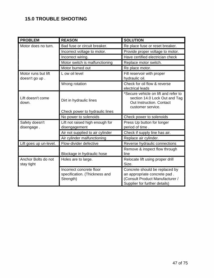
15.0 TROUBLE SHOOTING PROBLEM REASON SOLUTION
Motor does no turn. Bad fuse or circuit breaker. Re place fuse or reset breaker.
Incorrect voltage to motor. Provide proper voltage to motor.
Incorrect wiring. Have certified electrician check
Motor switch is malfunctioning Replace motor switch.
Motor burned out Re place motor.
Motor runs but lift L ow oil level Fill reservoir with proper doesn't go up . hydraulic oil.
Wrong rotation Check for oil flow & reverse electrical leads
Lift doesn't come down.
Dirt in hydraulic lines
*Secure vehicle on lift and refer to section 14.0 Lock Out and Tag Out Instruction. Contact customer service.
Check power to hydraulic lines
No power to solenoids Check power to solenoids
Safety doesn't Lift not raised high enough for Press Up button for longer disengage . disengagement period of time .
Air not supplied to air cylinder Check if supply line has air.
Air cylinder malfunctioning Replace air cylinder.
Lift goes up un-level. Flow-divider defective Reverse hydraulic connections
Remove & inspect flow through Blockage in hydraulic hose line
Anchor Bolts do not Holes are to large. Relocate lift using proper drill stay tight Size.
Incorrect concrete floor Concrete should be replaced by specification. (Thickness and an appropriate concrete pad . Strength) (Consult Product Manufacturer / Supplier for further details)

48 of 75
16.0 RECORD OF MAINTENANCE / TRAINING Records of all lift maintenance and operator training should be recorded in the following table.
MAINTENANCE & TRAINING PERFORMED
DATE
BY:
NOTES

49 of 75
17.0 LIFT ASSEMBLY
REPLACE WORN, DAMAGED OR BROKEN PARTS WITH PARTS APPROVED BY THE ORIGINAL
EQUIPMENT MANUFACTURER ONLY

50 of 75
17.1 Lift Assembly Parts List
51 of 75
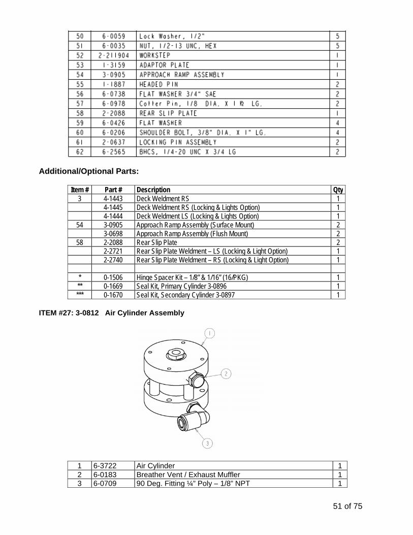
Additional/Optional Parts:
Item # Part # Description Qty3 4-1443 Deck Weldment RS 1 4-1445 Deck Weldment RS (Locking & Lights Option) 1 4-1444 Deck Weldment LS (Locking & Lights Option) 1
54 3-0905 Approach Ramp Assembly (Surface Mount) 2 3-0698 Approach Ramp Assembly (Flush Mount) 2
58 2-2088 Rear Slip Plate 2 2-2721 Rear Slip Plate Weldment – LS (Locking & Light Option) 1 2-2740 Rear Slip Plate Weldment – RS (Locking & Light Option) 1 * 0-1506 Hinge Spacer Kit – 1/8” & 1/16” (16/PKG) 1 ** 0-1669 Seal Kit, Primary Cylinder 3-0896 1 *** 0-1670 Seal Kit, Secondary Cylinder 3-0897 1
ITEM #27: 3-0812 Air Cylinder Assembly 1 6-3722 Air Cylinder 1
2 6-0183 Breather Vent / Exhaust Muffler 13 6-0709 90 Deg. Fitting ¼” Poly – 1/8” NPT 1

52 of 75
18.0 REAR SLIP PLATE TRANSFER BALL ARRANGEMENT
Item # Part # Description Qty. / Deck 1 1-3762 Plastic Insert 19 2 6-3974 Transfer Ball 35

53 of 75
19.0 HYDRAULIC & AIR ASSEMBLY

54 of 75

55 of 75
19.1 Line Routing Parts List
1 2 3/8” HYDRAULIC HOSE – CYLINDER (LS/RS) 2-2143 2 1
1 3/8” HYDRAULIC HOSE – LS 3/8” HYDRAULIC HOSE – RS
2-2718 2-2719
3 2 3/8” HYDRAULIC HOSE – EQUALIZE (LS/RS) 2-2717 6 1 ¼” POLYTUBE SAFETY AIR LINE 6-3020 7 2 VELOCITY FUSE 6-2956 10 2 90 DEG ELBOW, 3/8” JIC-M, 3/8’ JIC-F 6-0813 11 1 90 DEG ELBOW, ¼” NPT-M, 3/8” POLYTUBE 6-3010 12 1 TERMINAL BOLT, ¾” 6-0713 13 1 BRANCH TEE FITTING, ¼ NPT, F-F-M 6-3896 14 2 90 DEG ELBOW, 1/8” NPT, ¼” POLYTUBE 6-0709 15 1 TEE FITTING, ¼” POLYTUBE 6-2971 16 2 FRONT COVER 2-2185 17 6 HEX BOLT, ¼” NC x ¾” LG 6-0178 18 2 LOCKWASHER, ¼” 6-0056 19 1 3/8” POLYTUBE SUPPLY AIRLINE 6-3019 23 6 PIPE CLAMP, 3/8” 6-0170 24 14 PIPE CLAMP, ½” 6-0536 25 6 PIPE CLAMP, 5/8” 6-1547 26 24 SELF THREADING SCREW 6-1134 27 2 POLYTUBE RETURN LINE 3/8” 6-3082 32 2 90 DEG ELBOW, 3/8” NPT-M, 3/8” POLYTUBE 6-3058 33 2 FRONT COVER 2-2803 34 2 BASEFRAME LINE COVER LH 2-2299 37 2 HEX SOCKET CAP SCREW #10-24 UNCx 1”LG 6-3096 38 2 FLOOR LINE COVER “B” 2-2734 39 2 FLOOR LINE COVER “C” 2-2735 40 2 FLOOR LINE COVER “A” 2-2733 41 2 FLOOR LINE COVER “D” 2-2736 42 1 BASEFRAME LINE COVER RH 2-2301 44 3 WASHER FLAT ¼ SAE 6-0060
47 NAIL-IN ANCHORS, ¼” X 1” LG 6-0141

56 of 75
20.0 HEIGHT LIMIT ASSEMBLY
Note: Height Limit Sensor is located under Rear of Driver Side Deck.
20.1 HEIGHT LIMIT / LEVELING PARTS LIST
Item # Part # Description Qty.
1 1-3770 Sensor Track 12 1-3771 Sensor Bracket 13 6-3964 Limit Switch w/ Roller Lever 14 6-0008 Hex Head bolt, 1/4”-20UNC x 1” Lg. 25 6-0060 Flat Washer, ¼” 46 6-0056 Lock Washer, ¼” 27 6-0032 Nut, ¼”-20UNC 28 6-3965 Pan Hd Machine Screw, 8-32 x 1”lg 2
12 6-1134 Threat Cutting Screw, #12 x ½”lg 3

57 of 75
20.2 EQUALIZE SENSORS PARTS LIST
Note: Equalizing Sensors are located under Front of Driver & Passenger Side Deck.
20.3 HEIGHT LIMIT / LEVELING PARTS LIST
Item # Part # Description Qty. 1 6-3964 Limit Switch w/ Roller Lever 1 2 6-3943 Branch Y, 3/8” – ¼” 1 3 6-3928 Reducer, ¼” – 5/32” 2 4 6-3011 Tee fitting, 3/8” 1 5 6-3019 3/8” Polytube Supply Airline 1 6 8-0378 4mm Polytube Blue (ft) 53 8-0377 4mm Polytube Red (ft) 125
7 6-0536 Clamp, ½” 2 8 6-1134 Thread Cutting Screw, #12 x ½” Lg. 2 9 6-3984 Machine Screw, #8 x 1-1/2” lg. 2 10 1-3777 Plastic spacer 2

58 of 75
20.4 OPTIONAL: LIGHT KIT SENSOR PARTS LIST
Item # Part # Description Qty.
1 2-2757 Plastic Cam 12 6-0295 Flat Washer, 5/16” 13 6-0674 Lock Washer, 5/16” 14 6-0293 Hex Head bolt, 5/16”-18UNC x 1” Lg. 15 6-1792 Shoulder Bolt, 3/8” x ½” Lg. 16 6-0062 Flat Washer, 3/8” 17 6-0340 Circlip 28 1-3754 Hinge Pin, Cam 19 1-3752 Spacer 1
10 1-3771 Sensor Bracket 111 6-3965 Machine screw, #8-32 x 1”lg 212 6-3964 Limit Switch w/ Roller Lever 113 6-3944 Union, ‘Y’, 5/32” (4mm) Polytube 1 * 8-0378 4mm Polytube Blue 40 ft * 8-0377 4mm Polytube Red 40 ft
Note: Light Kit Sensor Assembly is located under Passenger Side Deck.

59 of 75
21.0 ACCESSORY ASSEMBLY
21.1 Front Turnplate
60 of 75
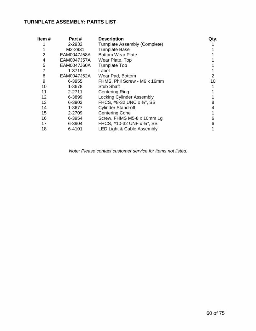
TURNPLATE ASSEMBLY: PARTS LIST
Item # Part # Description Qty.
1 1
2-2932 M2-2931
Turnplate Assembly (Complete) Turnplate Base
1 1
2 EAM0047J58A Bottom Wear Plate 1 4 EAM0047J57A Wear Plate, Top 1 5 EAM0047J60A Turnplate Top 1 7 1-3719 Label 1 8 EAM0047J52A Wear Pad, Bottom 2 9 6-3955 FHMS, Phil Screw - M6 x 16mm 10
10 1-3678 Stub Shaft 1 11 2-2711 Centering Ring 1 12 6-3899 Locking Cylinder Assembly 1 13 6-3903 FHCS, #8-32 UNC x ¾”, SS 8 14 1-3677 Cylinder Stand-off 4 15 2-2709 Centering Cone 1 16 6-3954 Screw, FHMS M5-8 x 10mm Lg 6 17 6-3904 FHCS, #10-32 UNF x ¾”, SS 6 18 6-4101 LED Light & Cable Assembly 1
Note: Please contact customer service for items not listed.

61 of 75
21.2 Rear Slip Plate Locking Mechanism
Item # Part # Description Qty. 1 1-0757 Nylon Thrust Washer 4 2 1-3686 Spacer 1 3 2-2712 Retainer Jaw 2 4 6-3900 Cylinder Assembly 1 5 6-3883 Cylinder Assembly 1 6 6-3882 Washer, Nylon ¼” ID 5/8” OD 2 7 6-3929 Cotter Pin, 3/16” x 2” lg, SS 1 8 6-0060 Flat Washer, ¼” ID 6 9 6-3907 Shoulder Bolt, ¼” x 5/8” lg. SS 2

62 of 75
21.3 Airline Routing for Locking Turnplates and Rear Slip Plates

63 of 75
Airline Parts List
Item Part Number Description Location Qty/Lift
1 1-3733 Air Line, Blue, 1/4”, 35’ From Console, on floor, on scissors, up to deck hinge
2
2 1-3732 Air Line, Red, 1/4”, 35’ From Console, on floor, on scissors, up to deck hinge
2
3 1-3735 Air Line, Blue, 1/4", 7.8’ On decks, from hinge to front 2
4 1-3734 Air Line, Red, 1/4", 7.8’ On decks, from hinge to front 2
5 6-3950 Tube Clamp On decks, at front 2
6 6-2971 Fitting, Tee, 1/4" On decks / On decks, at middle 8
7 1-3736 Air Line, Red, 1/4", 3.1’ On decks, from hinge to middle 2
8 1-3737 Air Line, Blue, 1/4", 3.1’ On decks, from hinge to middle 2
9 1-3741 Air Line, Blue, 1/4", 1.25’ On decks, feeding middle clamp 2
11 1-3740 Air Line, Red, 1/4", 1.25’ On decks, feeding middle clamp 2
12 1-3738 Air Line, Red, 1/4", 8.25’ On decks, middle to rear 2
13 1-3739 Air Line, Blue, 1/4", 8.25’ On decks, middle to rear 2
14 1-3742 Air Line, Red, 1/4", 5” Between clamp cylinders, rear and middle
4
15 1-3743 Air Line, Blue, 1/4", 7” Between clamp cylinders, rear and middle
4
* 6-3940 Adhesive Clamps 9/32” Front to turnplate 2

64 of 75
21.4 Rear LED Light Assembly: Exploded View
Top of Deck – Rear Slip Plate
Underside of Deck – Connection of LED Light Bar
*Note: Objects in pictures may not be exactly as shown.

65 of 75
REAR LED LIGHT ASSEMBLY: Parts List
Item # Part # Description Qty. 1 2-2721 Rear Slip Plate Weldment, LS 1 2-2740 Rear Slip Plate Weldment, RS 1
2 6-4092 6-4091
LED Light Bar w/ mounts & connector (Left side) LED Light Bar w/ mounts & connector (Right side)
1 1
3 6-3936 Push Retainer 4 4 6-3940 Adhesive Back Clamps 6 5 6-4089 Cable Extension Assembly (LS) 1 6-4093 Cable Extension Assembly (RS) 1
66 of 75
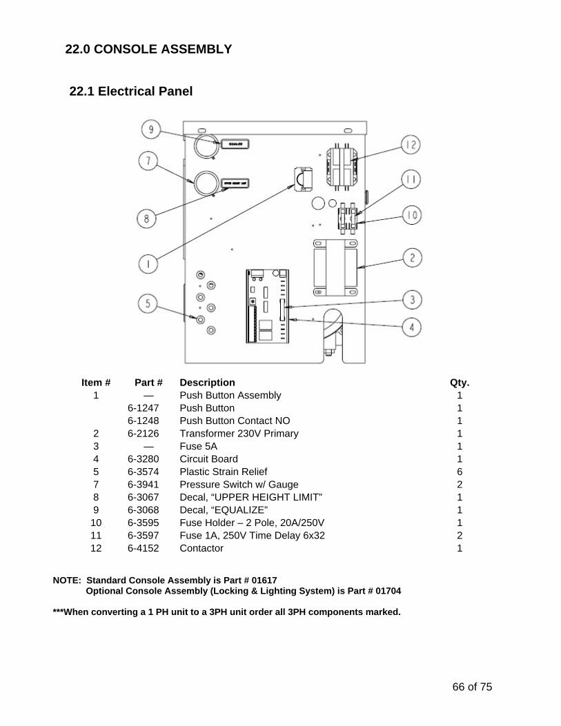
22.0 CONSOLE ASSEMBLY
22.1 Electrical Panel
Item # Part # Description Qty.
1 — Push Button Assembly 1 6-1247 Push Button 1 6-1248 Push Button Contact NO 1
2 6-2126 Transformer 230V Primary 13 — Fuse 5A 14 6-3280 Circuit Board 15 6-3574 Plastic Strain Relief 67 6-3941 Pressure Switch w/ Gauge 28 6-3067 Decal, “UPPER HEIGHT LIMIT” 19 6-3068 Decal, “EQUALIZE” 1
10 6-3595 Fuse Holder – 2 Pole, 20A/250V 111 6-3597 Fuse 1A, 250V Time Delay 6x32 212 6-4152 Contactor 1
NOTE: Standard Console Assembly is Part # 01617 Optional Console Assembly (Locking & Lighting System) is Part # 01704 ***When converting a 1 PH unit to a 3PH unit order all 3PH components marked.

67 of 75
22.2 Console: Pneumatic & Filtering System
Item # Part # Description Qty.1 6-4142 Water Separator / Regulator / Lubricator Kit 12 6-1055 Control Valve 13 6-3729 Union ‘Y’, ¼” Polytube 24 6-0709 Swivel Elbow, 1/8” NPT x ¼” Polytube 25 6-3730 Swivel ‘T’ Adapter, ¼” NPT M x 3/8” Polytube 16 6-3731 Reducer, 3/8” Stem x ¼” Polytube 17 6-3942 Union, M5 x 4mm Polytube 28 6-3985 Branch ‘Y’, M5 x 4mm Polytube 19
10 8-0141 6-0015
¼” Polytube (ft) 90 Elbow ¼ NPT
5ft 1
11 6-3928 Reducer 1 12 13
6-3952 6-4015
Check Valve, ¼ Poly M10 x 1.5 Pushnut Retainer
1 1

68 of 75
22.3 Console: Pneumatic & Filtering System - Locking & Light System (Optional)
Item # Part # Description Qty.
1 6-4142 Water Separator/Regulator/Lubricator Ass’y 12 6-1055 Control Valve (Safety Release) 13 4
6-3729 6-4015
Union ‘Y’, 1/4” Poly M10 x 1.5 Pushnut Retainer
5 2
5 6-3905 Valve Assembly (Locking Plates) 16 6-0708 Adapter, 1/8” NPT – 1/4” Poly 17 8
6-3977 6-0015
Breather, Female 1/8” NPT 90 Elbow ¼ NPT
1 1
9 6-3731 Reducer, 3/8” Stem x 1/4” Poly 110 6-3730 Swivel Tee Adapter, 1/4”NPT x 3/8” Poly 111 6-0709 Swivel Elbow, 1/8” NPT M x 1/4” Poly 212 6-2971 Pushlock Tee, 1/4” Poly 113 6-3928 Reducer, 1/4” Stem x 5/32” (4mm) Poly 114 15
6-40886-3952
LED Driver Box AssemblyCheck Valve, 1/4” Poly
11
16 6-3942 Union, M5 X 4mm Polytube 2 17 6-3941 Pressure Switch w/ Gauge 2 18 19
6-3985 6-0015
Branch ‘Y’, M5 x 4mm Polytube 90 Elbow ¼ NPT
1 1

69 of 75
22.4 PNEUMATIC LIMIT SWITCH SCHEMATIC

70 of 75
Item # Part # Description Qty.1 6-4142 Water Separator / Regulator / Lubricator Kit 12 6-3730 Swivel ‘T’ Adapter, ¼” NPT M x 3/8” Polytube 13 6-3731 Reducer, 3/8” Stem x ¼” Polytube 14 6-3729 Union ‘Y’, ¼” Polytube 15 6-3928 Reducer 3 6 6-3011 Union T, 3/8” Polytube 17 6-3010 90 Deg. Elbow, ¼” NPT-M – 3/8” Polytube 18 6-0713 Terminal Bolt, ¾” 19 6-3943 Branch Y, 3/8” Polytube – ¼” Polytube 1
10 6-3964 Limit Switch, Roller Lever 311 6-3941 Pressure Switch 212 6-3985 Branch Y, M5 x 4mm Polytube 113 6-3942 Union, M5 x 4mm Polytube 114 6-0015 90 Elbow ¼ NPT 1

71 of 75
22.5 Control Panel
Item # Part # Description Qty. 1 — Push Button Assembly 2 6-1247 Push Button - Arrow 1 6-1248 Push Button Contact NO 1
2 6-2314 Plastic Plug 1 3 — Air Valve Assembly 1 6-1055 Air Safety Release Valve 1 6-0709 90° Elbow 1 6-0708 ¼” Polytube x 1/8” M NPT Adapter 1
4 — Emergency Stop Button Assembly 1 6-2921 Emergency Stop Push Button 1 6-2922 Emergency Stop Contact NC 1
5 6-3558 Safety Release Decal 1 6 6-3557 Emergency Stop Decal 1 7 6-3623 Duty Cycle Decal 1
* Optional: Locking Turnplates & Slip Plates 8 6-3905 Valve Assembly 1 9 6-3910 Lock / Unlock Decal 1
1
2
3
4
5
6 7
8 9 * *

72 of 75
22.6 Console Panel Assembly
* Note: may not be exactly as shown.
Item# Part# Description Qty. 1 3-0973 Console Front/Side Panel 1 2 2-2512 Console Rear Panel 1 3 3-0974 Electrical Panel 1 4 2-2513 Top Cover 1
includes 6-0141 Concrete Nail ¼” x 1” Lg. 4 6-3075 Screw #10-24 x 5/8” 12 6-3074 U-Type Fastener 12 6-0816 Flat Washer, #10 12

73 of 75
23.0 POWERPACK ASSEMBLY
23.1 Powerpack Assembly

74 of 75
Item # Part # Description Qty. 1 6-0087 Motor, 220V (1 Phase) 1 6-0446 Motor, 220V (3 Phase) 1 6-0447 Motor, 575V (3 Phase) 1
2 6-2537 Motor Coupler 1 3 6-2984 Cap Screw, M6x20 2 4 6-2507 Bellhousing 1 5 6-2547 Lock Washer, Internal Tooth, 3/8” 4 6 6-2558 Cap Screw, Hex HD, 3/8”-16UNC x 1 ½” LG 4 7 6-1370 ½” Strain Relief Connector (1 Phase) 1 6-0094 ½” Strain Relief Connector (3 Phase) 1
9 6-2985 Check Valve 1 10 6-2986 Relief Valve (4650 PSI) 1 11 6-2987 Main Body 1 12 6-2988 Flow Control 1 13 6-2129 Spool Valve (c/w Manual Override) 1 14 6-3877** Manifold Assembly 1
**See Next Page for Manifold Assembly 15 1-3625 DIN Connector (24V) Assembly 5 16 6-2128 Square Coil (24V) 1 17 6-2989 Mainbody Assembly 1 18 6-2990 Return Filter Assembly 1 19 6-2991 Tandem Pump 1 20 6-3631 Long Inlet Strainer Assembly 1 21 6-3632 Short Inlet Strainer Assembly 1 24 6-2555 Unloading Manifold Assembly 1 25 6-3633 Return Tube Assembly 1 26 6-0674 Lock Washer, 5/16” 4 27 6-2533 Cap Screw, Hex HD, 5/16”-18UNC x 6 ½” LG 2 28 6-3638 Oil Tank 15L 1 30 6-2996 Oil Tank O-Ring 1 31 6-3223 Filler / Breather Cap 1 34 6-0284 Tee Fitting 3/8” JIC, F-M-M 2 35 6-3889 BHSCS, ¼”-20UNC X ½” LG 3 36 2-2719 Hydraulic Hose 1 37 2-2718 Hydraulic Hose 1 38 2-2143 Primary Hydraulic Hose 2 39 2-2717 Equalizing Hydraulic Hose 2 40 6-3082 3/8” Polytube Return Lines 2 42 6-3058 90 Deg Elbow 3/8” NPT to 3/8” Polytube 1 43 6-3474 Hydraulic Gauge, 0-5000 PSI 2 44 2-2592 Hydraulic Hose Assembly 1 45 6-3890 Plug (Oil Fill) 1 46 6-3894 Pressure Fitting w/ Bonded Seal 1 47 6-3563 Button Head Screw M10 X 45MM 2 48 6-0215 Spacer 2 49 6-3892 Lock Washer, M10 2 50 6-3011 Pushlock Tee Fitting, 3/8” Poly 1
*NOTE 6-3881 Pump Assembly

75 of 75
23.2 Manifold Parts List
Note: Complete Assembly Part # 6-3877
Item# Part# Description Qty. 1 6-3885 Manifold Block 1 2 6-3891 Adapter, Elbow SAE #6 M – 3/8” JIC M 1 3 6-2129 Manual Cartridge Valve 2 4 6-3403 Cartridge Valve 2 5 6-2128 Square Coil 24V 4 6 6-2548 Pressure Switch (Includes Bonded Seal) 1 7 6-3001 Adapter SAE #6 M – 3/8” JIC M 3 8 6-3888 Adapter SAE #6 M – 3/8” JIC F 1