1489-M Circuit Breakers · 1489-M Circuit Breakers 6 Rockwell Automation Publication...
18
Features Rockwell Automation Publication 1492-SG123D-EN-P — March 2014 5 1489-M Circuit Breakers Bulletin 1489-M thermal-magnetic Circuit Breakers are approved for branch circuit protection in the United States and Canada, and are certified as Miniature Circuit Breakers for IEC applications. These branch protectors are compatible with many accessories to meet diverse application needs, including UL 508 Listed bus bars for convenience in panel assembly, auxiliary contacts, signal contacts and shunt trips for versatility, and lockout attachments for safety during maintenance. Current limiting Fast breaking time High rated voltage Superior shock and vibration resistance to help prevent nuisance tripping Dual terminals allow a more secure connection of two wires, or both a wire and bus bar Terminal design helps prevent wiring misses by directing wires into the terminal openings, even while tightening Reversible line and load connections Single and multi-pole toggle mount lock out attachments available for Lockout/Tagout (LOTO) RoHS compliant and fully recyclable device Suitable for extreme ambient conditions 1489-M Circuit Breakers Rated Voltage UL/CSA: Max. 480Y/277V AC IEC: U e 230/400V AC Interrupting Capacity UL/CSA: 10 kA IEC: 15 kA Current Ratings 0.5...63 A Poles 1, 2, 3 Trip Curves C, D Standards Compliance UL 489 CSA C22.2 No. 5.1 EN 60947-2 GB 14048.2 Certifications UL Listed, File No. E197878 CSA Certified, File No. 259391 CE Marked VDE Certified CCC Certified RoHS Compliant IP20 finger-safe design (all sides) Suitable for DIN Rail mounting Accepts right-mounted shunt trips, auxiliary and signal contacts Terminal design helps prevent wiring misses Dual terminals provide wiring/bus bar flexibility and clamp from both sides to improve connection reliability Indicator window reflects contact state red: closed, green: open Scratch and solvent resistant printing
Transcript of 1489-M Circuit Breakers · 1489-M Circuit Breakers 6 Rockwell Automation Publication...

Features
Rockwell Automation Publication 1492-SG123D-EN-P — March 2014 5
1489-M Circuit Breakers
Bulletin 1489-M thermal-magnetic Circuit Breakers are approved for branch circuitprotection in the United States and Canada, and are certified as Miniature Circuit Breakersfor IEC applications.
These branch protectors are compatible with many accessories to meet diverseapplication needs, including UL 508 Listed bus bars for convenience in panel assembly,auxiliary contacts, signal contacts and shunt trips for versatility, and lockout attachmentsfor safety during maintenance.
� Current limiting� Fast breaking time� High rated voltage � Superior shock and vibration resistance to help prevent nuisance tripping� Dual terminals allow a more secure connection of two wires, or both a wire and bus bar� Terminal design helps prevent wiring misses by directing wires into the terminal
openings, even while tightening� Reversible line and load connections� Single and multi-pole toggle mount lock out attachments available for Lockout/Tagout
(LOTO)� RoHS compliant and fully recyclable device � Suitable for extreme ambient conditions
1489-M Circuit Breakers
Rated VoltageUL/CSA: Max. 480Y/277V ACIEC: Ue 230/400V AC
InterruptingCapacity
UL/CSA: 10 kA IEC: 15 kA
Current Ratings 0.5...63 A
Poles 1, 2, 3
Trip Curves C, D
StandardsCompliance
UL 489
CSA C22.2 No. 5.1
EN 60947-2
GB 14048.2
Certifications
UL Listed, File No. E197878
CSA Certified, File No. 259391
CE Marked
VDE Certified
CCC Certified
RoHS Compliant
IP20 finger-safe design(all sides)
Suitable for DIN Rail mounting
Accepts right-mountedshunt trips, auxiliary and signal contacts
Terminal design helpsprevent wiring misses
Dual terminals providewiring/bus bar flexibility
and clamp from both sides to improve connection reliability
Indicator window reflects contact state
red: closed, green: open
Scratch and solvent resistant printing
1489-M Circuit Breakers
Rockwell Automation Publication 1492-SG123D-EN-P — March 20146
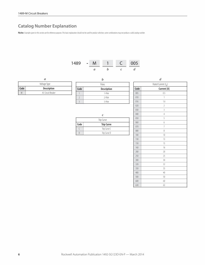
aVoltage Type
Code DescriptionM AC Circuit Breaker
bPoles
Code Description1 1-Pole
2 2-Pole
3 3-Pole
cTrip Curve
Code Trip CurveC Trip Curve C
D Trip Curve D
dRated Current (In)
Code Current [A]005 0.5
010 1
016 1.6
020 2
030 3
040 4
050 5
060 6
070 7
080 8
100 10
130 13
150 15
160 16
200 20
250 25
300 30
320 32
350 35
400 40
500 50
600 60
630 63
1489 - M 1 C 005a b c d
Catalog Number ExplanationNote: Examples given in this section are for reference purposes. This basic explanation should not be used for product selection; some combinations may not produce a valid catalog number.

1489-M Circuit Breakers
Rockwell Automation Publication 1492-SG123D-EN-P — March 2014 7
1-Pole Circuit Breakers
Photo/Wiring Diagram UL/CSA Max. Voltage IEC/EN Max. VoltageContinuous Current Rating
(In) [A]
Trip Curve CInductive5...10 InCat. No.
Trip Curve DHighly Inductive
10...20 InCat. No.
277V AC,48V DC
230V AC
0.5 1489-M1C005 1489-M1D005
1 1489-M1C010 1489-M1D010
1.6 1489-M1C016 1489-M1D016
2 1489-M1C020 1489-M1D020
3 1489-M1C030 1489-M1D030
4 1489-M1C040 1489-M1D040
5 1489-M1C050 1489-M1D050
6 1489-M1C060 1489-M1D060
7 1489-M1C070 1489-M1D070
8 1489-M1C080 1489-M1D080
10 1489-M1C100 1489-M1D100
13 1489-M1C130 1489-M1D130
15 1489-M1C150 1489-M1D150
16 1489-M1C160 1489-M1D160
20 1489-M1C200 1489-M1D200
25 1489-M1C250 1489-M1D250
1
1-pole2
30 1489-M1C300 1489-M1D300
32 1489-M1C320 1489-M1D320
35 1489-M1C350 1489-M1D350
C Curve: 277V AC, 48V DCD Curve: 240V AC, 48V DC
40 1489-M1C400 1489-M1D400
240V AC, 48V DC
50 1489-M1C500 1489-M1D500
60 1489-M1C600 1489-M1D600
63 1489-M1C630 1489-M1D630
Product Selection

1489-M Circuit Breakers
Rockwell Automation Publication 1492-SG123D-EN-P — March 20148
2-Pole Circuit Breakers
Photo/Wiring Diagram UL/CSA Max. Voltage IEC/EN Max. VoltageContinuous Current Rating
(In) [A]
Trip Curve CInductive5...10 InCat. No.
Trip Curve DHighly Inductive
10...20 InCat. No.
480Y/277V AC,96V DC
400V AC
0.5 1489-M2C005 1489-M2D005
1 1489-M2C010 1489-M2D010
1.6 1489-M2C016 1489-M2D016
2 1489-M2C020 1489-M2D020
3 1489-M2C030 1489-M2D030
4 1489-M2C040 1489-M2D040
5 1489-M2C050 1489-M2D050
6 1489-M2C060 1489-M2D060
7 1489-M2C070 1489-M2D070
8 1489-M2C080 1489-M2D080
10 1489-M2C100 1489-M2D100
13 1489-M2C130 1489-M2D130
15 1489-M2C150 1489-M2D150
16 1489-M2C160 1489-M2D160
20 1489-M2C200 1489-M2D200
25 1489-M2C250 1489-M2D250
1 3
42-pole
2
30 1489-M2C300 1489-M2D300
32 1489-M2C320 1489-M2D320
35 1489-M2C350 1489-M2D350
C Curve: 480Y/277V AC, 96V DCD Curve: 240V AC, 96V DC
40 1489-M2C400 1489-M2D400
240V AC, 96V DC
50 1489-M2C500 1489-M2D500
60 1489-M2C600 1489-M2D600
63 1489-M2C630 1489-M2D630
Product Selection
1489-M Circuit Breakers
Rockwell Automation Publication 1492-SG123D-EN-P — March 2014 9
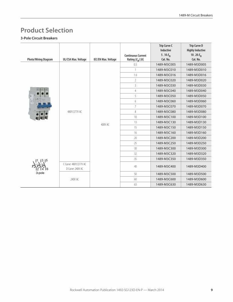
3-Pole Circuit Breakers
Photo/Wiring Diagram UL/CSA Max. Voltage IEC/EN Max. VoltageContinuous Current
Rating (In) [A]
Trip Curve CInductive5...10 InCat. No.
Trip Curve DHighly Inductive
10...20 InCat. No.
480Y/277V AC
400V AC
0.5 1489-M3C005 1489-M3D005
1 1489-M3C010 1489-M3D010
1.6 1489-M3C016 1489-M3D016
2 1489-M3C020 1489-M3D020
3 1489-M3C030 1489-M3D030
4 1489-M3C040 1489-M3D040
5 1489-M3C050 1489-M3D050
6 1489-M3C060 1489-M3D060
7 1489-M3C070 1489-M3D070
8 1489-M3C080 1489-M3D080
10 1489-M3C100 1489-M3D100
13 1489-M3C130 1489-M3D130
15 1489-M3C150 1489-M3D150
16 1489-M3C160 1489-M3D160
20 1489-M3C200 1489-M3D200
25 1489-M3C250 1489-M3D250
1 3 5
4 63-pole 2
30 1489-M3C300 1489-M3D300
32 1489-M3C320 1489-M3D320
35 1489-M3C350 1489-M3D350
C Curve: 480Y/277V ACD Curve: 240V AC
40 1489-M3C400 1489-M3D400
240V AC
50 1489-M3C500 1489-M3D500
60 1489-M3C600 1489-M3D600
63 1489-M3C630 1489-M3D630
Product Selection

1489-M Circuit Breakers
Rockwell Automation Publication 1492-SG123D-EN-P — March 201410
SpecificationsElectrical Ratings
Poles 1, 2, 3
Tripping characteristics C, D
Rated current (In) 0.5...63 A
Rated frequency [f] 50/60 Hz
Rated insulation voltage Ui per IEC/EN 60664-1250V AC (phase to ground)440V AC (phase to phase)
Overvoltage category III
Pollution degree 3
Data per UL/CSA
Ratedvoltage
AC
1-pole
C Curve0.5...40 A 277V AC
50...63 A 240V AC
D Curve0.5...35 A 277V AC
40...63 A 240V AC
2-, 3-pole
C Curve0.5...40 A 480Y/277V AC
50...63 A 240V AC
D Curve0.5...35 A 480Y/277V AC
40...63 A 240V AC
DC1-pole 48V DC
2-pole 96V DC (2-pole in series)
Rated interrupting capacity per UL 489 10 kA
Reference temperature for tripping characteristics 40 °C
Electrical endurance6,000 operations
(AC and DC); 1 cycle (1s - ON, 9s - OFF)
Data per IEC/EN 60947-2
Rated operationalvoltage (Ue)
1-pole 230V AC
2-, 3-pole 400 V AC
Highest supply orutilization voltage(Umax)
AC1-pole 253/440V AC
2-, 3-pole 440V AC
DC �1-pole 48V DC
2-pole 96V DC
Min. operating voltage 12V AC, 12V DC
Rated ultimate short-circuit breaking capacity (Icu) 15 kA
Rated service short-circuit breaking capacity (Ics)≤40 A: 11.25 kA
>40 A: 7.5 kA
Rated impulse withstand voltage Uimp. (1.2/50μs) 4 kV (test voltage 6.2kV atsea level, 5kV at 2,000m)
Dielectric test voltage 2 kV (50/60Hz, 1 min.)
Reference temperature for tripping characteristics 30 °C
Electrical endurance1 cycle (2s - ON, 13s - OFF, In ≤ 32A), 1 cycle (2s - ON, 28s - OFF,In > 32A)
In < 30A :20,000 ops.(AC)In ≥ 30A:10,000 ops. (AC)
1,000 ops. (DC)
� Self-declared IEC DC ratings.
Mechanical DataHousing Insulation group II, RAL 7035
Indicator window red ON/green OFF
Protection degree per EN 60529 IP20, IP40 in enclosure with cover
Mechanical endurance 20,000 operations
Shock resistance per IEC/EN 60068-2-27 25 g - 2 shocks - 13 ms
Vibration resistance per IEC/EN 60068-2-6 5g - 20 cycles at 5...150...5 Hz withload 0.8 In
EnvironmentalEnvironmental conditions (damp heat) per IEC/EN 60068-2-30
28 cycles with 55°C/90-96% and25°C/95-100%
Ambient temperature� -25...+55 °C
Storage temperature -40...+70 °C
InstallationTerminal Dual terminal
Cross-section of conductors♣ –solid, stranded (front/back terminalslot)
mm2 35/35 mm2
AWG 18...4/18...10 AWG
Cross-section of conductors – flexible mm2 25/10 mm2
Multi-wire rating per UL, CSAAWG 1 wire, 18...4 AWG
AWG 2 wires‡, 18...10 AWG
Cross-section of bus bars (backterminal slot) mm2 10 mm2
Tightening torque
N•m 2.8 N•m
in•lbAWG 18...16: 8.85 in•lb, AWG 14...10: 17.7 in•lb,
AWG 8...4:39.8 in•lb
Screwdriver No. 2 Pozidrive
Mounting DIN Rail (EN 60715, 35 mm) with fastclip
Mounting position Any
Supply Optional
Approximate Dimensions and Weight
Pole dimensions (H x D x W) 111 x 69 x 17.5 mm (4.37 x 2.72 x.69")
Pole weight 125 g (4.4 oz.)
Combination with Auxiliary ElementsAuxiliary contact Yes
Signal contact Yes
Shunt trip Yes
♣ 35 mm self-declared, not included in IEC/EN approval.
� Refer to the ambient temperature derating tables.
‡ Wires must be of like size and stranding. Only one wire per terminal slot.
1489-M Circuit Breakers
Rockwell Automation Publication 1492-SG123D-EN-P — March 2014 11
Note: Dimensions are shown in millimeters (inches). Dimensions are not intended for manufacturing purposes.
Approximate Dimensions
Power Loss Due to Current
Rated Current [A]Power Loss Per
Pole [W] Rated Current [A]Power Loss Per
Pole [W]0.5 1.4 15 2.4
1 1.4 16 2.5
1.6 1.8 20 2.5
2 1.8 25 3.2
3 1.6 30 3.5
4 1.8 32 3.7
5 1.9 35 4.1
6 2.0 40 4.5
7 1.1 50 4.5
8 1.5 60 4.9
10 2.1 63 5.4
13 2.3 — —
17.5 mm(0.69”)
67 mm (2.6”)
84.8 mm(3.34”)
111 mm(4.37”)
74 mm (2.9”)
1-Pole
35.0 mm(1.38”)
52.5 mm(2.06”)
69 mm (2.7”)
84.8 mm(3.34”)
111 mm(4.37”)
75 mm (3.0”)
2-, 3-Pole 2-Pole 3-Pole
1-Pole
Zero-stack Derating
The installation of several miniature circuit breaker side by side with rated current on all polesrequires a correction factor to the rated current (not required if spacers are used).
No. of Adjacent Devices Factor1 1
2,3 0.9
4,5 0.8
≥ 6 0.75

1489-M Circuit Breakers
Rockwell Automation Publication 1492-SG123D-EN-P — March 201412
Bulletin 1489-M circuit breakers may be used to protectbranch circuits. A branch circuit is the wiring portion of asystem extending beyond the final overcurrent deviceprotecting the circuit. Guidelines established in NEC, CEC, UL,and CSA should be used to determine the specific device.For example:
Motor Branch CircuitBulletin 1489-M circuit breakers are not horsepower ratedbecause they are able to safely interrupt currents far inexcess of the locked rotor value for a selected motor. Thisability is recognized in the codes and standards and is alsoestablished by the UL and CSA tests described in UL 489and CSA C22.2 No. 5 standards.
The size of a Bulletin 1489-M circuit breaker should bedetermined following the guidelines for an Inverse TimeCircuit Breaker.
References: NEC 430.51 and UL 489. Also see CEC andappropriate Canadian Standards.
Transformer ProtectionBulletin 1489-M circuit breakers may be used fortransformer protection following the guidelinesestablished.
References: NEC 450 and UL 489. Also see CEC and appropriateCanadian Standards.
Branch Circuits
Application InformationCircuit VoltageThe Bulletin 1489-M circuit breakers are rated by voltageclass. Applications should not exceed the listed voltage andcurrent range.
Circuit FrequencyThe Bulletin 1489-M circuit breakers may be applied tofrequencies of 50 Hz and 60 Hz without derating. Forapplications above 60 Hz, contact Rockwell Automation withspecific application information for the derating of the circuitbreakers.
Available Short Circuit Current
The Bulletin 1489-M circuit breakers should only be appliedin those applications in which the available short-circuit (orfault) current is less than or equal to 10 kA (US/Canada) and15 kA (IEC).
Application Considerations
Tripping Characteristics
The trip curve characteristics are shown on the followingpages. The trip bands shown for each breaker representcurrent tripping limits for a circuit breaker and are within thelimits established by UL.
The standard tripping characteristic for Bulletin 1489-M isType C. Type C has a magnetic trip activated at 5-10 timesthe rated current of the circuit breaker. The referencetemperature for the thermal tripping characteristics is 30 °C.The Type C characteristic will suit most applications.
In rare occurrences when the Type C characteristic does notfully meet the application, Type D magnetic tripcharacteristic is available, allowing for transientsapproximately twice as high as the standard Type C.
For a specific current at 30 °C, a circuit breaker will open("clear the circuit") automatically at some total time that willbe within the minimum and maximum time shown on thecurves. For example, a one-pole, 15 A, Bulletin 1489-M circuitbreaker trips in not less than 1 s and not more than 200 s ona 30 A current. Because the UL standard defines this timespread, users should not specify exact tripping time. Thelower current portion of the curves (upper left) depicts thetime to trip due to thermal action and reflect overloadprotection of the wire and connect load. The higher currentportion of the curves (lower right) depicts the trip due tomagnetic action of the circuit breaker and reflects protectiondue to short circuit level currents.
The following is a discussion of application considerationsrelated to North American applications. When applying productto IEC regional requirements, follow IEC practices and guidelines.
The selection of a specific ampere rating for a specificapplication is dependent on the type of load and duty cycleand is governed by the National Electrical Code (CanadianElectrical Code) and UL/CSA. In general, the codes requirethat overcurrent protection is at the current supply and atpoints where wire sizes are reduced. In addition, the codesstate that conductors be protected according to their currentcarrying capacity. There are specific situations that requireapplication consideration, such as motor circuit, andguidelines for the selection for transformer protection.
The Bulletin 1489-M circuit breakers are “non-100% rated” asdefined by UL 489, para 7.1.4.2. As such, the circuit breaker'srating should be loaded to no more than 80% if used withcontinuous loads.
Line and load may be reversed. The Bulletin 1489-M circuitbreaker may be bottom fed.

1489-M Circuit Breakers
Rockwell Automation Publication 1492-SG123D-EN-P — March 2014 13
HACR Rating
Bulletin 1489-M Circuit Breakers are rated as Heating, AirConditioning and Refrigeration circuit breakers as defined byUL 489, paragraph 6.7 and may used in this type ofapplication.
SWD Rating
The Bulletin 1489-M breakers (0.5 … 20 A) are rated as SwitchDuty (SWD) and as such may be applied to switchfluorescent lighting loads up to their current and voltagemaximum.
Bulletin 1489-M Circuit Breakers are rated as current limitingcircuit breakers as defined by UL 489, paragraph 8.6.
The Bulletin 1489-M line features the ability to achieve shortcircuit interruptions far more effectively than conventionalbreakers. In conventional circuit breakers, the short circuitinterruption time required is approximately one or two halfcycles of an AC sine wave. When the contacts open, theresulting arc continues to burn until the current level passesthrough zero. The arc may re-ignite because of theinsufficient width of the contact gap. The current that flowsuntil the arc is extinguished produces a heating effectproportional to the I2t value (let-through-energy) of the faultcurrent.
The Bulletin 1489-M device is designed to substantiallyreduce the amount of let-through-current and the resultinglet-through-energy that can damage protected components.The Bulletin 1489-M has the ability to interrupt short circuitcurrent within the first half cycle of the fault. Limiting let-through current and energy will protect against the harmfuleffects of overcurrent and is focused primarily on avoidingexcessive heat and mechanical damage.
Where an orderly shutdown is required to minimize thehazards to personnel and equipment, a system ofcoordination based upon the faulted or overloaded circuit isisolated by selective operation of only the overcurrentprotective device closest to the overcurrent condition. Theuser should select devices that meet this requirement.References: NEC 240.12. Also see CEC.
Coordinated Overcurrent Protection
Current Limiting
Heater Load, Lighting, and Other Load ProtectionBulletin 1489-M circuit breakers may be used for protectionof heater loads, lighting loads, and other loads followingthe guidelines established.
References: NEC Article 31 and UL 508A. Also see CEC andappropriate Canadian Standards.
Both of these factors are proportional to the square of thecurrent. Thermal energy is proportional to the square of theRMS value and magnetic forces are proportional to thesquare of the peak value. The most effective way to provideprotection is to substantially limit let-through-energy. Thisprovides the following advantages:
� Far less damage at the location of the short circuit.
� Fast electric separation of a faulty unit from the system,especially power supplies connected in parallel that areswitched off when the voltage of the power bus dropsbelow a certain level.
� Far less wear on the miniature circuit breaker itself. Thismeans more safe interruptions.
� Better protection of all components in the short circuitpath.
� Far wider range of selective action when used with anupstream protective device. (No nuisance shut downsfrom feeder line interruptions, causing a blackout in allconnected branches.)

1489-M Circuit Breakers
Rockwell Automation Publication 1492-SG123D-EN-P — March 201414
Ambient Temperature Derating
Reference temperature = 40 °CTemperature Derating, UL
Bulletin 1489-M
-25 -20 -10 0 10 20 30 40 50 550.5 0.6 0.6 0.6 0.6 0.6 0.5 0.5 0.5 0.5 0.5
1 1.2 1.2 1.2 1.1 1.1 1.1 1.0 1 1.0 0.91.6 2.0 2.0 1.9 1.8 1.8 1.7 1.7 1.6 1.5 1.5
2 2.5 2.4 2.4 2.3 2.2 2.1 2.1 2 1.9 1.93 3.7 3.7 3.6 3.4 3.3 3.2 3.1 3 2.9 2.84 5.0 4.9 4.7 4.6 4.4 4.3 4.1 4 3.9 3.85 6.2 6.1 5.9 5.7 5.6 5.4 5.2 5 4.8 4.76 7.4 7.3 7.1 6.9 6.7 6.4 6.2 6 5.8 5.77 8.7 8.6 8.3 8.0 7.8 7.5 7.3 7 6.7 6.68 9.9 9.8 9.5 9.2 8.9 8.6 8.3 8 7.7 7.6
10 12.4 12.2 11.9 11.5 11.1 10.7 10.4 10 9.6 9.413 16.1 15.9 15.4 14.9 14.4 14.0 13.5 13 12.5 12.315 18.6 18.3 17.8 17.2 16.7 16.1 15.6 15 14.4 14.216 19.8 19.6 19.0 18.4 17.8 17.2 16.6 16 15.4 15.120 24.8 24.4 23.7 23.0 22.2 21.5 20.7 20 19.3 18.925 31.0 30.6 29.6 28.7 27.8 26.9 25.9 25 24.1 23.630 37.2 36.7 35.6 34.4 33.3 32.2 31.1 30 28.9 28.332 39.7 39.1 37.9 36.7 35.6 34.4 33.2 32 30.8 30.235 43.4 42.8 41.5 40.2 38.9 37.6 36.3 35 33.7 33.140 49.6 48.9 47.4 45.9 44.4 43.0 41.5 40 38.5 37.850 62.0 61.1 59.3 57.4 55.6 53.7 51.9 50 48.2 47.260 74.4 73.3 71.1 68.9 66.7 64.4 62.2 60 57.8 56.763 78.2 77.0 74.7 72.3 70.0 67.7 65.3 63 60.7 59.5
Current Rating [A]
Ambient temperature (°C)
Reference temperature = 30 °CTemperature Derating, IEC
Bulletin 1489-M
-25 -20 -10 0 10 20 30 40 50 550.5 0.6 0.6 0.6 0.5 0.5 0.5 0.5 0.5 0.5 0.5
1 1.2 1.2 1.1 1.1 1.1 1.0 1 1.0 0.9 0.91.6 1.9 1.8 1.8 1.7 1.7 1.6 1.6 1.6 1.5 1.5
2 2.3 2.3 2.2 2.2 2.1 2.1 2 1.9 1.9 1.93 3.5 3.5 3.4 3.3 3.2 3.1 3 2.9 2.8 2.84 4.7 4.6 4.5 4.4 4.2 4.1 4 3.9 3.8 3.75 5.8 5.8 5.6 5.5 5.3 5.2 5 4.9 4.7 4.66 7.0 6.9 6.7 6.5 6.4 6.2 6 5.8 5.6 5.67 8.2 8.1 7.8 7.6 7.4 7.2 7 6.8 6.6 6.58 9.3 9.2 9.0 8.7 8.5 8.2 8 7.8 7.5 7.4
10 11.7 11.5 11.2 10.9 10.6 10.3 10 9.7 9.4 9.313 15.1 15.0 14.6 14.2 13.8 13.4 13 12.6 12.2 12.015 17.5 17.3 16.8 16.4 15.9 15.5 15 14.6 14.1 13.916 18.6 18.4 17.9 17.4 17.0 16.5 16 15.5 15.0 14.820 23.3 23.0 22.4 21.8 21.2 20.6 20 19.4 18.8 18.525 29.1 28.8 28.0 27.3 26.5 25.8 25 24.3 23.5 23.130 35.0 34.5 33.6 32.7 31.8 30.9 30 29.1 28.2 27.832 37.3 36.8 35.8 34.9 33.9 33.0 32 31.0 30.1 29.635 40.8 40.3 39.2 38.2 37.1 36.1 35 34.0 32.9 32.440 46.6 46.0 44.8 43.6 42.4 41.2 40 38.8 37.6 37.050 58.3 57.5 56.0 54.5 53.0 51.5 50 48.5 47.0 46.360 69.9 69.0 67.2 65.4 63.6 61.8 60 58.2 56.4 55.563 73.4 72.5 70.6 68.7 66.8 64.9 63 61.1 59.2 58.3
Current Rating [A]
Ambient temperature (°C)
Note: Application below 0º C is for non-condensing atmosphere. Care should be taken for applications below 0 °C. Thesedevices are not certified to operate correctly in the presence of ice.
The Bulletin 1489-M circuit breakers are rated in RMSamperes at a 40 °C (104 °F) ambient temperature per UL489/CSA C22.2 No. 5. This temperature is used as theambient temperature external to an industrial enclosure. If acircuit breaker is applied in a temperature that exceeds the40 °C (104 °F) ambient rating, then the circuit breaker shouldbe derated using the table below. For IEC 60947-2 standard,the products carry an ambient rating of 30 °C. Followstandard IEC application considerations for temperaturerating in different ambient temperatures.

1489-M Circuit Breakers
Rockwell Automation Publication 1492-SG123D-EN-P — March 2014 15
Tripping CharacteristicsC Curve D Curve

1489-M Circuit Breakers
Rockwell Automation Publication 1492-SG123D-EN-P — March 201416
AccessoriesRight Mount
PhotoProduct Description
�‡ Contacts Standards CertificationsUL/CSA Max.
Current/VoltageIEC Ratings
Current/Voltage Cat. No.
Shunt TripC1
C2
UL 489CSA 22.2 No. 5EN 60947-5-2
UL ListedCSA Certified
CE Marked
110...415V AC110...250V DC
— 1489-AMST1
UL 489CSA 22.2 No. 5EN 60947-5-2
UL ListedCSA Certified
CE Marked12...60V AC/DC — 1489-AMST2
Signal Contact
1 N.O./N.C.(1 C.O.)
UL 489CSA 22.2 No. 5EN 60947-5-1
GB 14048.5
UL ListedCSA Certified
CE MarkedVDE CertifiedCCC Certified
1A @ 480V AC2A @ 277V AC
1.5A @ 125V DC2A @ 60V DC4A @ 24V DC
2A @ 230V (AC-14)1A @ 400V (AC-14)
1.5A @ 110V (DC-12)1A @ 220V (DC-12)4A @ 24V (DC-13)2A @ 60V (DC-13)
1489-AMRS39698
95
Auxiliary Contact
1 N.O./N.C.(1 C.O.)
UL 489CSA 22.2 No. 5EN 60947-5-1
GB 14048.5
UL ListedCSA Certified
CE MarkedVDE CertifiedCCC Certified
1A @ 480V AC2A @ 277V AC
1.5A @ 125V DC2A @ 60V DC4A @ 24V DC
2A @ 230V (AC-14)1A @ 400V (AC-14)
1.5A @ 110V (DC-12)1A @ 220V (DC-12)4A @ 24V (DC-13)2A @ 60V (DC-13)
1489-AMRA31214
11
�A maximum of one shunt trip, two signal contacts, or two auxiliary contacts may be installed per 1489-M.
‡ A maximum of three accessories may be installed per 1489-M. The shunt trip must be mounted closest to the 1489-M, then the signal contact, then the auxiliary contact(s). For allowed combinations, and installation instructions please contact yourlocal Rockwell Automation sales office or Allen-Bradley distributor.
Toggle Mount
Photo Product Description Cat. No.
Lock-out attachment for 1-pole MCB 189-ALOA1
Lock-out attachment for multi-pole MCB 189-ALOA2

1489-M Circuit Breakers
Rockwell Automation Publication 1492-SG123D-EN-P — March 2014 17
Accessory Approximate DimensionsNote: Dimensions are shown in millimeters (inches). Dimensions are not intended for manufacturing purposes.
8.8 mm (0.35”)
74 mm(2.91”)
99 mm (3.90”)
1489-AMRS3
17.5 mm (0.69”)
74 mm(2.91”)
99 mm (3.90”)
64.2 mm (2.53”)
1489-AMST1 and 1489-AMST2
8.8 mm (0.35”)
74 mm(2.91”)
99 mm (3.90”)
1489-AMRA3

1489-M Circuit Breakers
Rockwell Automation Publication 1492-SG123D-EN-P — March 201418
Note: Do not cut bus bars. Maximum of 3 bus bars allowed in anycombination of the same phase configuration. Multiple bus barsmust be installed back-to-back.
1489-M Bus Bar Accessories
Description Pkg. Qty.Cat. No.�
Terminal Power Feed, 35 mm2 10 1489-AMCLT35
Dedicated Power Feed, 50 mm2 10 1489-AMCLT50D
Protective Shroud (for unused pins) 10 1489-AMCLPS
� cULus, UL 508, EN 60947-1, CE Marked
1489-M Bus Bars
Phase No. of PinsNo. of Circuit
Breakers Pkg Qty.Cat. No.�‡
1-Phase
6 6 10 1489-AMCL106
12 12 10 1489-AMCL112
18 18 10 1489-AMCL118
2-Phase
6 3 10 1489-AMCL206
12 6 10 1489-AMCL212
18 9 10 1489-AMCL218
3-Phase
6 2 10 1489-AMCL306
12 4 10 1489-AMCL312
18 6 10 1489-AMCL318
� cULus, UL 508, EN 60947-1, CE Marked‡ Maximum of three bus bars allowed
Bus Bars
AWG lb-in Nm14
12-86-2
21
2536
2.32.84.0
Z2
1489-M3...
1489-AMCLPS
4 mm
1489-AMCLT50D
1489-AMCLT35

1489-M Circuit Breakers
Rockwell Automation Publication 1492-SG123D-EN-P — March 2014 19
Bus Bar Approximate DimensionsNote: Dimensions are shown in millimeters (inches). Dimensions are not intended for manufacturing purposes.
1-Phase Bus Bars
1489 -AMCL118
32.5 mm(1.28”)
15.5 mm(0.61”)
46 mm(1.81”)
1.5 mm(0.06”)
310.2 mm(12.21”)
17 x 17.6 mm = 299.2 mm(17 x 0.69” = 11.78”)
5
99 mm(3.90”)
17.6 mm(0.69”) 5 x 17.6 mm = 88 mm
(5 x 0.69” = 3.46”)
5 mm(0.19”)
204.6 mm(8.06”)
11 x 17.6 mm = 193.6 mm(11 x 0.69” = 7.62”)
17.6 mm(0.69”)
5 mm(0.19”)
17.6 mm(0.69”)
5 mm(0.19”)
1489-AMCL1121489-AMCL106

1489-M Circuit Breakers
Rockwell Automation Publication 1492-SG123D-EN-P — March 201420
2-Phase Bus Bars
17.6
5
32.5 mm(1.28”)
15.5 mm(0.61”)
46 mm(1.81”)
1.5 mm(0.06”)
17 x 17.6 mm = 299.2 mm(17 x 0.69” = 11.78”)
99 mm(3.90”)
17.6 mm(0.69”) 5 x 17.6 mm = 88 mm
(5 x 0.69” = 3.46”)
5 mm(0.19”)
204.6 mm(8.06”)
17.6 mm(0.69”)
5 mm(0.19”)
5 mm(0.19”)
310.2 mm(12.21”)
11 x 17.6 mm = 193.6 mm(11 x 0.69” = 7.62”)
17.6 mm(0.69”)
1489-AMCL218
Bus Bar Approximate DimensionsNote: Dimensions are shown in millimeters (inches). Dimensions are not intended for manufacturing purposes.
1489-AMCL206 1489 -AMCL212

1489-M Circuit Breakers
Rockwell Automation Publication 1492-SG123D-EN-P — March 2014 21
3-Phase Bus Bars
55
32.5 mm(1.28”)
15.5 mm(0.61”)
46 mm(1.81”)
1.5 mm(0.06”)
17 x 17.6 mm = 299.2 mm(17 x 0.69” = 11.78”)
99 mm(3.90”)
17.6 mm(0.69”)
5 x 17.6 mm = 88 mm(5 x 0.69” = 3.46”)
5 mm(0.19”)
204.6 mm(8.06”)
17.6 mm(0.69”)
5 mm(0.19”)
5 mm(0.19”)
310.2 mm(12.21”)
11 x 17.6 mm = 193.6 mm(11 x 0.69” = 7.62”)
17.6 mm(0.69”)
1489-AMCL318
1489-AMCL306 1489 -AMCL312
Bus Bar Approximate DimensionsNote: Dimensions are shown in millimeters (inches). Dimensions are not intended for manufacturing purposes.

1489-M Circuit Breakers
Rockwell Automation Publication 1492-SG123D-EN-P — March 201422
14 mm(0.55”)
6 mm(0.23”)
72.1 mm(2.84”)
16.2 mm(0.64”)
3 mm(0.12”)
31.1 mm(1.22”)
1489-AMCLT35
17.8 mm(0.70”)
28.8 mm(1.13”)
51 mm(2.0”)
17.6mm(0.69”)
4 mm(0.15”)
12.6 mm(0.50”)
6 mm(0.23)
31.2 mm(1.23”)
1489-AMCLT50D
13 mm(0.51”)
7 mm(0.28”)
48.2 mm(1.9”)
17.8 mm(0.70”)
2 X 17.6 mm = 35.2 mm(2 x 0.69” = 1.39”)
16 mm(0.63”)
24 mm(0.94”)
3.6 mm(0.14”)
17.6 mm(0.69”)
1489-AMCLPS
Bus Bar Accessory Approximate DimensionsNote: Dimensions are shown in millimeters (inches). Dimensions are not intended for manufacturing purposes.