1474 IEEE ANTENNAS AND WIRELESS …tslwcf/PDF_Publications/2012_CP_AW… · with CP antenna design...
4
1474 IEEE ANTENNAS AND WIRELESS PROPAGATION LETTERS, VOL. 11, 2012 Characteristic-Mode-Based Improvement of Circularly Polarized U-Slot and E-Shaped Patch Antennas Yikai Chen, Member, IEEE, and Chao-Fu Wang, Senior Member, IEEE Abstract—Characteristic mode (CM) analysis is carried out to understand the underlying physics of two popular circularly polar- ized (CP) microstrip patch antennas, namely U-slot and E-shaped CP patch antennas, for achieving better performance. Modifica- tions of these two CP antennas with optimal feed position and com- pact patch size are explicitly obtained through examining the CMs, modal significance, and characteristic angle. Compared to conven- tional designs, the two modified designs have better axial ratio (AR) and cross-polarization performance without introducing any addi- tional design cost or complexity. It is also interesting to find that: 1) offset probe feed in CP U-slot patch antennas will provide ex- cellent AR performance; 2) cutting off the redundant section from CP E-shaped patch antenna will yield low cross polarization and more compact configuration. Index Terms—Characteristic modes, circular polarization, microstrip antennas. I. INTRODUCTION C IRCULARLY polarized (CP) microstrip antennas are popular and attractive in applications such as global po- sitioning systems (GPS), mobile satellite, and RFID design [1]. Previous studies revealed that CP microstrip antennas can be viewed as the superposition of two linear polarized modes with equal amplitude and quadrature phase excitations. Investiga- tions have also shown that the most important issue associated with CP antenna design is how to optimize the patch shapes and recognize the two linear polarized modes to be combined for circular polarization. Unfortunately, CP antenna design is usually accomplished by tuning patch shapes and feed positions through parameter sweeps or using automated optimization techniques[2], [3]. With these methods, the design procedure becomes a rather trivial task and also lacks of physical concepts. Recently, the usefulness of characteristic mode (CM) theory in antenna de- signs has been recognized by many groups [4]–[7]. It has been proposed to design CP antenna through theoretical simulation of an isosceles-triangular patch antenna [7]. This letter focuses on how to apply the CM theory as an ef- ficient way to modify two commonly used CP antennas, i.e., U-slot [8] and E-shaped patch antennas [9]. It will be shown Manuscript received November 07, 2012; accepted November 26, 2012. Date of publication November 30, 2012; date of current version December 20, 2012. The authors are with Temasek Laboratories, National University of Singapore, Singapore 117411, Singapore (e-mail: [email protected]; [email protected]). Color versions of one or more of the figures in this letter are available online at http://ieeexplore.ieee.org. Digital Object Identifier 10.1109/LAWP.2012.2231046 Fig. 1. Circularly polarized U-slot antenna with offset feed: (a) the geometry; (b) the prototype. Dimensions: mm, mm, mm, mm, mm, mm, mm, mm. that CMs of the two CP antennas give clear underlying physics of their CP performance, which explicitly results in newly mod- ified designs with improved performance. Fabricated prototypes experimentally validate the effectiveness of the proposed design method. II. METRIC QUANTITIES FOR CHARACTERISTIC MODES For the sake of brevity, the details of the CM theory [10] are omitted here and only two quantities, i.e., characteristic angle and modal significance as the function of eigenvalue [6], [7], are respectively defined in (1) and (2) as follows: (1) (2) The characteristic angle physically characterizes the phase angle between a characteristic current and the associated char- acteristic field. Hence, a mode is at resonance when its charac- teristic angle is close to 180 . The modal significance represents the contribution of a particular mode to the total radiation when a source or excitation is applied. III. CP U-SLOT PATCH ANTENNA DESIGN Different from a symmetrical U-slot in linear polarized an- tennas, an unsymmetrical U-slot is cut in the patch to get two or- thogonal linear polarizations, rather than extend the impedance bandwidth. Fig. 1 shows the geometry and prototype of the proposed CP U-slot antenna. The probe feed position is dif- ferent from that in [8]. The radiating patch is fabricated using a 0.5-mm-thick copper sheet. Characteristic-mode analysis is first carried out for the U-slot patch over a frequency band of 2.2–2.7 GHz. For this problem, the first two characteristic modes are sufficient to describe the 1536-1225/$31.00 © 2012 IEEE
Transcript of 1474 IEEE ANTENNAS AND WIRELESS …tslwcf/PDF_Publications/2012_CP_AW… · with CP antenna design...

1474 IEEE ANTENNAS AND WIRELESS PROPAGATION LETTERS, VOL. 11, 2012
Characteristic-Mode-Based Improvement ofCircularly Polarized U-Slot and E-Shaped
Patch AntennasYikai Chen, Member, IEEE, and Chao-Fu Wang, Senior Member, IEEE
Abstract—Characteristic mode (CM) analysis is carried out tounderstand the underlying physics of two popular circularly polar-ized (CP) microstrip patch antennas, namely U-slot and E-shapedCP patch antennas, for achieving better performance. Modifica-tions of these two CP antennas with optimal feed position and com-pact patch size are explicitly obtained through examining the CMs,modal significance, and characteristic angle. Compared to conven-tional designs, the twomodified designs have better axial ratio (AR)and cross-polarization performance without introducing any addi-tional design cost or complexity. It is also interesting to find that:1) offset probe feed in CP U-slot patch antennas will provide ex-cellent AR performance; 2) cutting off the redundant section fromCP E-shaped patch antenna will yield low cross polarization andmore compact configuration.
Index Terms—Characteristic modes, circular polarization,microstrip antennas.
I. INTRODUCTION
C IRCULARLY polarized (CP) microstrip antennas arepopular and attractive in applications such as global po-
sitioning systems (GPS), mobile satellite, and RFID design [1].Previous studies revealed that CP microstrip antennas can beviewed as the superposition of two linear polarized modes withequal amplitude and quadrature phase excitations. Investiga-tions have also shown that the most important issue associatedwith CP antenna design is how to optimize the patch shapesand recognize the two linear polarized modes to be combinedfor circular polarization.Unfortunately, CP antenna design is usually accomplished
by tuning patch shapes and feed positions through parametersweeps or using automated optimization techniques[2], [3].With these methods, the design procedure becomes a rathertrivial task and also lacks of physical concepts. Recently, theusefulness of characteristic mode (CM) theory in antenna de-signs has been recognized by many groups [4]–[7]. It has beenproposed to design CP antenna through theoretical simulationof an isosceles-triangular patch antenna [7].This letter focuses on how to apply the CM theory as an ef-
ficient way to modify two commonly used CP antennas, i.e.,U-slot [8] and E-shaped patch antennas [9]. It will be shown
Manuscript received November 07, 2012; accepted November 26, 2012. Dateof publication November 30, 2012; date of current version December 20, 2012.The authors are with Temasek Laboratories, National University of
Singapore, Singapore 117411, Singapore (e-mail: [email protected];[email protected]).Color versions of one or more of the figures in this letter are available online
at http://ieeexplore.ieee.org.Digital Object Identifier 10.1109/LAWP.2012.2231046
Fig. 1. Circularly polarized U-slot antenna with offset feed: (a) the geometry;(b) the prototype. Dimensions: mm, mm, mm,
mm, mm, mm, mm, mm.
that CMs of the two CP antennas give clear underlying physicsof their CP performance, which explicitly results in newly mod-ified designs with improved performance. Fabricated prototypesexperimentally validate the effectiveness of the proposed designmethod.
II. METRIC QUANTITIES FOR CHARACTERISTIC MODES
For the sake of brevity, the details of the CM theory [10] areomitted here and only two quantities, i.e., characteristic angleand modal significance as the function of eigenvalue [6], [7],are respectively defined in (1) and (2) as follows:
(1)
(2)
The characteristic angle physically characterizes the phaseangle between a characteristic current and the associated char-acteristic field. Hence, a mode is at resonance when its charac-teristic angle is close to 180 . The modal significance representsthe contribution of a particular mode to the total radiation whena source or excitation is applied.
III. CP U-SLOT PATCH ANTENNA DESIGN
Different from a symmetrical U-slot in linear polarized an-tennas, an unsymmetrical U-slot is cut in the patch to get two or-thogonal linear polarizations, rather than extend the impedancebandwidth. Fig. 1 shows the geometry and prototype of theproposed CP U-slot antenna. The probe feed position is dif-ferent from that in [8]. The radiating patch is fabricated using a0.5-mm-thick copper sheet.Characteristic-mode analysis is first carried out for the U-slot
patch over a frequency band of 2.2–2.7 GHz. For this problem,the first two characteristic modes are sufficient to describe the
1536-1225/$31.00 © 2012 IEEE
CHEN AND WANG: CM-BASED IMPROVEMENT OF CP U-SLOT AND E-SHAPED PATCH ANTENNAS 1475
Fig. 2. Horizontal and vertical modes of the U-slot antenna: (a) characteristicangle; (b) modal significance.
nature electromagnetic behavior of the antenna. All the othermodes can be viewed as higher-order modes that are difficultto resonant in practice. Fig. 2 shows the characteristic angle andmodal significance of the first twomodes. It is found that the twomodes present exactly the same current amplitude and 90 phasedifference at 2.3 GHz. Moreover, Fig. 3 shows that mode ischaracterized as horizontal mode, with intense currents concen-trated at the end of the U-slot’s short arm. It is also evident thatmode can be identified as the vertical mode, with its intensecurrents concentrate at the end of the U-slot’s long arm. Thus, itis possible to get a CP antenna if the two orthogonal modes canbe excited simultaneously.In order to find the optimal probe positions, we subtract the
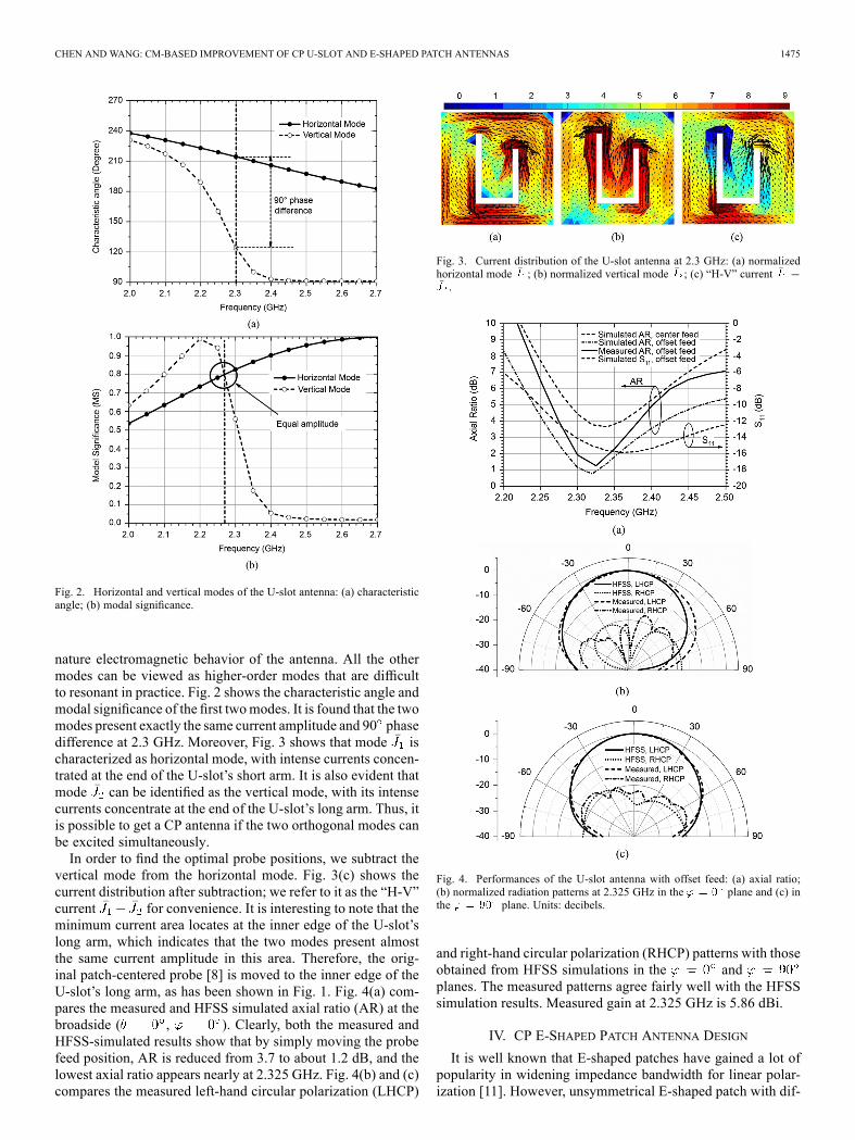
vertical mode from the horizontal mode. Fig. 3(c) shows thecurrent distribution after subtraction; we refer to it as the “H-V”current for convenience. It is interesting to note that theminimum current area locates at the inner edge of the U-slot’slong arm, which indicates that the two modes present almostthe same current amplitude in this area. Therefore, the orig-inal patch-centered probe [8] is moved to the inner edge of theU-slot’s long arm, as has been shown in Fig. 1. Fig. 4(a) com-pares the measured and HFSS simulated axial ratio (AR) at thebroadside ( , ). Clearly, both the measured andHFSS-simulated results show that by simply moving the probefeed position, AR is reduced from 3.7 to about 1.2 dB, and thelowest axial ratio appears nearly at 2.325 GHz. Fig. 4(b) and (c)compares the measured left-hand circular polarization (LHCP)
Fig. 3. Current distribution of the U-slot antenna at 2.3 GHz: (a) normalizedhorizontal mode ; (b) normalized vertical mode ; (c) “H-V” current.
Fig. 4. Performances of the U-slot antenna with offset feed: (a) axial ratio;(b) normalized radiation patterns at 2.325 GHz in the plane and (c) inthe plane. Units: decibels.
and right-hand circular polarization (RHCP) patterns with thoseobtained from HFSS simulations in the andplanes. The measured patterns agree fairly well with the HFSSsimulation results. Measured gain at 2.325 GHz is 5.86 dBi.
IV. CP E-SHAPED PATCH ANTENNA DESIGN
It is well known that E-shaped patches have gained a lot ofpopularity in widening impedance bandwidth for linear polar-ization [11]. However, unsymmetrical E-shaped patch with dif-

1476 IEEE ANTENNAS AND WIRELESS PROPAGATION LETTERS, VOL. 11, 2012
Fig. 5. Circularly polarized E-shaped patch antenna with reduced size: (a) thegeometry; (b) the prototype. Dimensions: mm, mm,mm, mm, mm, mm, mm, mm,
mm.
Fig. 6. First three characteristic modes of the E-shaped patch antenna: (a) char-acteristic angle; (b) modal significance.
ferent slot depths can be used to realize circular polarizationwith relatively narrow impedance bandwidth [9]. The geom-etry and prototype of the unsymmetrical E-shaped patch antennaare shown in Fig. 5. A foam with relative dielectric constant of
is used to support the E-shaped patch. The dimensionsare determined according to the fabricated prototype in [9]. Asobserved from our prototype, the redundant section is cut offfrom the one shown in Fig. 5(a), and we will show later that thesize-reduced antenna has more attractive performance.Fig. 6 shows the characteristic angle and modal significance
for the first three modes. It is found that modes and presentthe same current magnitude at 2.3 GHz, while modes andpresent the same current magnitude at 2.6 GHz. Fig. 7 showsthe normalized current distribution for the first three modes. It
Fig. 7. Characteristic current distribution of the E-shaped patch antenna:(a) mode and (b) mode at 2.3 GHz; (c) mode and (d) mode at2.6 GHz.
Fig. 8. Characteristic current distribution of the size-reduced E-shaped patchantenna at 2.3 GHz: (a) mode ; (b) mode .
is observed that modes and are characterized with ver-tical and horizontal currents, respectively, and is also a ver-tical current. Together with the information provided in Fig. 6,it is readily seen that and have the potential to be com-bined for circular polarization near 2.3 GHz. However, sinceis the dominant mode at 2.6 GHz, it cannot contribute to
the circular polarization. Therefore, even though we have notconsidered the feed structure yet, we can predict that satisfac-tory circular polarization performance can be obtained within anarrow frequency band near 2.3 GHz, but it is difficult to getgood circular polarization at 2.6 GHz. This is one of the mostimportant features that we can benefit from the theory of CMs,and it is also what makes the CM analysis different from othertraditional full-wave analysis.Moreover, observation of Fig. 7(b) illustrates that current dis-
tributed in Area I is much weaker than that in Area II. Thus,horizontal mode dominantly supporting the circular polariza-tion is mainly contributed from the current in Area II. In ad-dition, Fig. 7(a) shows that vertical mode current in Area I iscomparable to that in Area II. It is easy to learn that Area I isthe redundant section that does not contribute to circular polar-ization and will inevitably rise up the cross-polarization level.Therefore, with the expectation of reducing the high cross-po-larization level ( dB in the range of from broad-side) as described in [9], we cut the redundant section shown inFig. 5(a), and the characteristic current distributions for the sizereduced E-shaped patch antenna are shown in Fig. 8. As can be

CHEN AND WANG: CM-BASED IMPROVEMENT OF CP U-SLOT AND E-SHAPED PATCH ANTENNAS 1477
Fig. 9. Performances of the circular polarized E-shaped patch antenna: (a) re-flection coefficient; (b) axial ratio; (c) normalized radiation patterns at 2.45 GHzin the plane and (d) in the plane. Units: decibels.
observed, this cutting does not affect the vertical mode, but thehorizontal mode becomes more evident as compared to the onein Fig. 7(b). This fact demonstrates the feasibility of the redun-dant section cutting again.Performances of the size reduced E-shaped patch are shown
in Fig. 9. It is clearly seen that this cutting does not greatly affectthe reflection coefficient performance, but the axial ratios be-tween 2.7–2.8 GHz seem to degrade much. However, from [9],
we can see that the CP gain in this frequency range is 5–7.5 dBlower than that at 2.3 GHz. It is also well known that if the ARperformance is as good as those at low frequency, the gain athigher frequency band should be higher. Therefore, it is not safeto judge AR bandwidth by only considering the AR at broad-side direction. It is of utmost important to investigate the trueAR performance together with CP radiation patterns. From thispoint of view, the redundant area cutting does not degrade theCP performance over the effective frequency range.Fig. 9(c) and (d) shows the measured and simulated radiation
patterns. As compared to radiation patterns in [9], it is observedthat by simply cutting off the redundant area, the cross-polariza-tion level has been reduced to be below 15 dB in the angularrange of from broadside. Measured gain at 2.45 GHz isabout 8.87 dBi. Another benefit of the size-reduced design isthat it becomes more convenient for CP antenna array setup.
V. CONCLUSION
Applications of characteristic modes to commonly used CPU-slot and E-shaped patch antennas are presented. It has beenshown that characteristic modes provide valuable informationfor performance improvement, but it does not introduce any de-sign complexity. Experimental and simulated results are pre-sented to validate the effectiveness of the newly modified de-signs based on CM analysis. The optimized designs in this letterillustrate that: 1) an offset probe feed in CP U-slot patch an-tennas will provide excellent AR performance; 2) a redundantsection exists on the classic CP E-shaped patch antenna, andlower cross polarization can be obtained by cutting off it. It isexpected that CMwill benefit more CP antenna designs, and it isalso hoped that the conclusions we made for the CP U-slot andE-shaped patch antennas will be helpful to antenna engineers.
REFERENCES[1] K. L. Wong, Compact and Broadband Microstrip Antennas. New
York: Wiley, 2002, ch. 5.[2] R. Zentner, Z. Sipus, and J. Bartolic, “Optimization synthesis of broad-
band circularly polarized microstrip antennas by hybrid genetic algo-rithm,” Microw. Opt. Technol. Lett., vol. 31, no. 3, pp. 197–201, Nov.2001.
[3] R. L. Haupt, “Antenna design with a mixed integer genetic algorithm,”IEEE Trans. Antennas Propag., vol. 55, no. 3, pp. 577–582, Mar. 2007.
[4] Y. Chen and C. F. Wang, “Electrically loaded Yagi-Uda antenna op-timizations using characteristic modes and differential evolution,” J.Electromagn. Waves Appl., vol. 26, pp. 1018–1028, 2012.
[5] Y. Chen and C. F. Wang, “Synthesis of reactively controlled antennaarrays using characteristic modes and de algorithm,” IEEE AntennasWireless Propag. Lett., vol. 11, pp. 385–388, 2012.
[6] W. Wu and Y. P. Zhang, “Analysis of ultra-wideband printed planarquasi-monopole antennas using the theory of characteristic modes,”IEEE Antennas Propag. Mag., vol. 52, no. 6, pp. 67–77, Dec. 2010.
[7] M. Cabedo-Fabres, E. Antonino-Daviu, A. Valero-Nogueira, and M. F.Bataller, “The theory of characteristic modes revisited: A contributionto the design of antennas for modern applications,” IEEE AntennasPropag. Mag., vol. 49, no. 5, pp. 52–68, Oct. 2007.
[8] K. F. Tong and T. P. Wong, “Circularly polarized U-slot antenna,”IEEE Trans. Antennas Propag., vol. 55, no. 8, pp. 2382–2385, Aug.2007.
[9] A. Khidre, K. F. Lee, F. Yang, and A. Eisherbeni, “Wideband circularlypolarized E-shaped patch antenna for wireless applications,” IEEE An-tennas Propag. Mag., vol. 52, no. 5, pp. 219–229, Oct. 2010.
[10] R. F. Harrington and J. R. Mautz, “Theory of characteristic modes forconducting bodies,” IEEE Trans. Antennas Propag., vol. AP-19, no. 5,pp. 622–628, Sep. 1971.
[11] F. Yang, X. X. Zhang, X. Ye, and Y. Rahmat-Samii, “Wide-bandE-shaped patch antennas for wireless communications,” IEEE Trans.Antennas Propag., vol. 49, no. 7, pp. 1094–1100, Jul. 2001.


![Regenbogenkreis · 2017-10-26 · SOP M 1474, ICP/MS* DIN EN 15763 mod. SOP M 1474, ICP/MS* DIN EN 15763 mod.: sop M 1474, ICP/MS* Ergebnis/Result [mg/kg] 0,02 < Nachweisgrenze/ Grenzwert](https://static.fdocuments.in/doc/165x107/5f3820d418e2ca0fdb60b86f/regenbogenkreis-2017-10-26-sop-m-1474-icpms-din-en-15763-mod-sop-m-1474-icpms.jpg)