141 EVALUATION OF SPRAYED-ON METALIZING … FOR PRECAST PRESTRESSED CONCRETE ... EVALUATION OF...
24
141 EVALUATION OF SPRAYED-ON METALIZING FOR PRECAST PRESTRESSED CONCRETE I-BEAMS INNOVATIVE BRIDGE RESEARCH CONSTRUCTION (IBRC) PROGRAM PHYSICAL RESEARCH REPORT NO. 141 APRIL 2002
Transcript of 141 EVALUATION OF SPRAYED-ON METALIZING … FOR PRECAST PRESTRESSED CONCRETE ... EVALUATION OF...

141
EVALUATION OF SPRAYED-ONMETALIZING FOR PRECASTPRESTRESSED CONCRETEI-BEAMS
INNOVATIVE BRIDGE RESEARCH CONSTRUCTION(IBRC) PROGRAM
PHYSICAL RESEARCH REPORT NO. 141APRIL 2002

Technical Report Documentation Page
1. Report No.
FHWA/IL/PRR-1412. Government Accession No. 3. Recipient's Catalog No.
4. Title and Subtitle 5. Report Date
April 2002Evaluation of Sprayed-On Metalizing for Precast Prestressed ConcreteI-Beams
6. Performing Organization Code
8. Performing Organization Report N o.7. Author(s)
Mark Gawedzinski, P.E.PRR-141
9. Performing Organization Name and Address 10. Work Unit ( TRAIS)
Illinois Department of TransportationBureau of Materials and Physical Research
11. Contract or Grant No.
126 E. Ash St.Springfield, IL 62704
13. Type of Report and Period Covered
Final ReportAugust 2000 - April 2002
Illinois Department of TransportationBureau of Materials and Physical Research
126 E. Ash St.Springfield, IL 62704
14. Sponsoring Agency Code
15. Supplementary Notes
16. Abstract
Cathodic protection has been used as an effective means of arresting corrosion in reinforced concrete. Agalvanic system typically consists of a sacrificial anode, some form of adhesive or fastening system to securethe anode to the concrete, and a electrical connection between the anode and the corroded reinforcement. Noexternal power or complex monitoring system is required. Galvanic systems are recognized for their simplicityand ability to operate with little or no maintenance for the life of the system. This research was conducted toevaluate “sprayed-on” galvanic cathodic protection systems as a means of extending the life of precastprestressed concrete I-beams. By arresting corrosion, the galvanic system can extend the life of theprestressing strands and reinforcing steel, postponing or minimizing the need for repairing structural members ofthe bridge. The Illinois Department of Transportation, Bureau of Materials and Physical Research (IDOT BMPR)conducted an evaluation of three different types of zinc-based metals as anodes for galvanic cathodic protection.The anodes were “metallized” onto the faces of several pre-cast, pre-stressed concrete I-beams of twinstructures, west of Peoria, Illinois. This study was conducted to evaluate the metallizing process, and thedifferent metals as anodes for consideration as alternative methods for galvanic cathodic protection. Evaluationof the three different types of “spray on” anodes for galvanic cathodic protection indicate that the systems do notoffer any improved amount of protection to the pre-stressing strands when compared to beams that were nottreated. Results from the corrosion potential surveys indicate that the systems are not protecting the steel. Itappears that the anodes do not develop enough current necessary to drive the ion exchange to arrest thecorrosion process.
17. Key Words
Cathodic protection, galvanic systems, precast,prestressed I-beams. metallizing.
18. Distribution Statement
No restrictions. This document is available to the publicthrough the National Technical Information Service,Springfield, Virginia 22161.
19. Security Classif. (of this report)
Unclassified20. Security Classif. (of this page)
Unclassified21. No. of Pages
2322. Price
Form DOT F 1700.7 (8-72) Reproduction of completed page authorized

EVALUATION OF SPRAYED-ONMETALIZING FOR PRECASTPRESTRESSED CONCRETEI-BEAMS
By:
Mark Gawedzinski, P.E.Research Implementation Engineer
Illinois Department of TransportationBureau of Materials and Physical Research
126 E. Ash StSpringfield, Illinois 62704
April 2002

iii
TABLE OF CONTENTS
TECHNICAL REPORT DOCUMENTATION PAGE........................................................................i
TABLE OF CONTENTS................................................................................................................iii
ACKNOWLEDGEMENTS ............................................................................................................iv
DISCLAIMERS..............................................................................................................................iv
LIST OF FIGURES........................................................................................................................v
LIST OF PHOTOGRAPHS............................................................................................................v
LIST OF TABLES..........................................................................................................................v
INTRODUCTION ..........................................................................................................................1
SUPPORTING RESEARCH .........................................................................................................2
DESCRIPTION OF STUDY ..........................................................................................................4
RESULTS AND DISCUSSION OF THEIR SIGNIFICANCE........................................................11
CONCLUSIONS AND RECOMMENDATIONS...........................................................................18
iv
ACKNOWLEDGEMENTS
The author whishes to thank members of the District Four Bureau of Operations BridgeMaintenance Unit for their time and assistance in preparing and installing test equipmentassociated with the metallizing project. Mr. Joe Armstrong for his assistance in preparingthe electronic version of this report, and Messrs. Matt Mueller and David Lippert for theirtime in reviewing this report.
DISCLAIMERS
The content of this report reflects the views of the author, who is responsible for the factsand accuracy of the data presented herein. The contents of not necessarily reflect theofficial views or policies of the Illinois Department of Transportation. This reports does notconstitute a standard, specification or regulation.

v
LIST OF FIGURES
Figure 1. Framing Plan of twin structures.............................................................................4
Figure 2. Beam cross section detailing stirrup and pre-stressing strand locations...............5
Figure 3. Metallized area on beams and corrosion potential test sites.................................7
LIST OF PHOTOS
Photo 1. Power washed beam #6 with corrosion potential sites located..............................6
Photo 2. Removing concrete cover from stirrup...................................................................7
Photo 3. Beam #6, east side w/fiber tape cover over corrosion potential sites andexposed metal tie wires.........................................................................................8
Photo 4. Metallizing beam #6 with Zn/Al/In anode...............................................................9
Photo 5. Expanded steel plate before second metallizing pass.........................................10
Photo 6. Plate and wire covered with epoxy......................................................................10
Photo 7. Beam 2 west side Zn/Al anode corrosion products.............................................15
Photo 8. West Side of Beam 4...........................................................................................16
Photo 9. Beam 10, east side..............................................................................................17
Photo 10. Water short across concrete to anode.................................................................17
LIST OF TABLES
Table 1. Anode location description.....................................................................................5
Table 2. Corrosion Potential Survey Results................................................................12-13

1
Introduction
Cathodic protection has been used as an effective means of arresting corrosion in reinforcedconcrete. Active systems (impressed current) as well as passive systems (galvanic) have beenused to reduce the effects of corrosion. Impressed current systems use external power to driveion exchanges causing a repassification of the protective oxide layer formed at the reinforcingbar (rebar)-concrete interface. Drawbacks to impressed current systems are the cost andphysical requirements for external power and monitoring of the system.
A galvanic system typically consists of a sacrificial anode, some form of adhesive or fasteningsystem to secure the anode to the concrete, and a electrical connection between the anode andthe corroded reinforcement. No external power or complex monitoring system is required.Galvanic systems are recognized for their simplicity and ability to operate with little or nomaintenance for the life of the system.
This research was conducted to evaluate “sprayed-on” galvanic cathodic protection systems asa means of extending the life of precast prestressed concrete I-beams. By arresting corrosion,the galvanic system can extend the life of the prestressing strands and reinforcing steel,postponing or minimizing the need for repairing structural members of the bridge.
The Illinois Department of Transportation, Bureau of Materials and Physical Research (IDOTBMPR) conducted an evaluation of three different types of zinc-based metals as anodes forgalvanic cathodic protection. The anodes were “metallized” onto the faces of several pre-cast,pre-stressed concrete I-beams of twin structures, west of Peoria, Illinois. This study wasconducted to evaluate the metallizing process, and the different metals as anodes forconsideration as alternative methods for galvanic cathodic protection.

2
Supporting ResearchIDOT has four active impressed current cathodic protection systems throughout the state. Theirperformance has been somewhat limited due to continued operational problems. The titaniummesh, which is placed in a deck overlay, is prone to damage when patches are installed.Lightening strikes or current surges have disabled rectifiers and modems used for powerdistribution and communications. Recently, there has been a move to investigate theperformance of cheaper, more reliable galvanic systems. In addition to the metallized systemevaluated in this study, IDOT has evaluated the following passive cathodic protection systems.
3M Corporation, 4727 Zinc Hydrogel AnodeIn 1998, the Products Evaluation Unit of IDOT BMPR began an evaluation of a galvaniccathodic protection system marketed by the 3M Corporation. Known as 4727 Zinc HydrogelAnode, the system consisted of a 10-mil thick sheet of zinc foil coated with a 30-mil thick,ionically conductive, pressure sensitive adhesive hydrogel. A protective liner was placed on theback of the hydrogel/zinc assembly as it was rolled during production to prevent self-corrosionof the zinc.
Two sites in Peoria, Illinois were chosen in April of 1998 as the first test sites. One site was apier-cap of a roadway overpass along I-74, while the other site included parts of two structurescarrying I-474 over a township road. The system was relatively easy to install. It required anelectrical connection to the reinforcing steel, and a clean, dry concrete surface. Duringinstallation the protective liner was peeled away and the anode was firmly pressed onto theconcrete surface. The anode was placed on a pier cap for each structure as well as at theabutment end of two prestressed, precast portland cement concrete I-beams. The anode wasplaced over a length of 40 inches, from the end of the beam. The beams included one fascia(outside) beam and one interior beam. A corrosion potential survey was conducted todetermine the amount of active corrosion occurring at each location. After the survey wascompleted, the concrete surfaces were power-washed and allowed to dry before the anode wasinstalled. The locations of the corrosion potential test sites were reestablished to monitor theperformance of the anode. In September of 1998, a third site was established south of Lincoln,Illinois. The anode was placed on the abutment ends of twin structures carrying I-55 over theSpring Creek overflow channel. The anode was placed on each structure’s fascia beams, for atotal of eight test locations at the site. Installation proceeded as at the earlier sites, with fourcorrosion potential monitoring sites established on the outside of each fascia beam. Periodicmonitoring continued at each site.
Periodic evaluations in 1998, 1999 and 2000 of the beam ends at the Peoria sites indicated thatthe systems did conform to the NACE (National Association of Corrosion Engineers)specification of a 100 mV depolarization over 4 hours after the electrical circuit had beenbroken. However, it was noted where the anode was placed on the outside of the fascia beamsand in areas exposed to water from leaking joints, it was beginning to separate from the face ofthe precast concrete. The hydrogel in these areas had become brittle and had lost its adhesiveand conductive properties. Resistance tests on pieces of the brittle hydrogel indicated that ithad become an insulator rather than a conductor.
The anode installed at Lincoln, Illinois was observed on September 2, 1998; October 22, 1998;August 5, 1999; and July 7, 2000. Performance during the early observations had also initiallyconformed to the NACE recommended practice. However, evaluation of the anode on August5, 1999 revealed similar performance to that occurring in Peoria. The zinc had becomedebonded from the surface of the concrete in areas exposed to water. The July 7, 2000

3
evaluation revealed the debonded areas had enlarged as the anode dried out. Fragments ofthe anode could be seen on the slope wall in addition to visible gaps between the zinc and theconcrete. The failure of the hydrogel resulted in a termination of the study.
Vector Corrosion Technology, Galvashield.Vector Corrosion Technologies of Winnipeg, Manitoba, Canada, manufactures Galvashield, apalm sized, puck shaped, galvanic zinc core surrounded by a high pH mortar. Tie wiressecured to the zinc core provide the mechanical and electrical connections to reinforcing steel.IDOT BMPR Products Evaluation Unit began a field evaluation of Galvashield in June, 2001 inwhich several anodes were installed on bridge pier repairs and joint repairs associated with abridge carrying IL 10 over Sugar Creek west of Lincoln, Illinois. The evaluation is expected tocontinue to 2004.

4
Description of Study
In August of 2000, IDOT BMPR conducted an evaluation of three different types of zinc basedmetals for use as a “spray on” form of galvanic cathodic protection. The study was conducted toevaluate “sprayed-on” galvanic cathodic protection as a means of extending the life of pre-castpre-stressed concrete I-beams, so that repairs to critical areas such as beam webs and flanges,sole plates, and other corrosion prone areas are minimized.
The metals were applied to the ends of several Portland cement concrete pre-cast, pre-stressedI-beams, by a thermal spray (metallizing) process. Once the anodes were applied, they wereelectrically connected to the reinforcing steel of the beams, completing the cathodic protectioncircuits. Corrosion potentials of the beams were monitored and compared to untreated (control)beams to determine the effectiveness of the cathodic protection system.
The metals evaluated included pure zinc, as well as two zinc alloys; an 85/15% blend of zincand aluminum and a proprietary blend of zinc, aluminum, and indium. The experimental featurewas conducted at the north abutments of the twin structures (Structure Number 072-0116 &072-0117) carrying Interstate 474 over Pottstown Road in Peoria, Illinois. The structures wereconstructed in 1978 and rehabilitated in 2000, with new joints and nosings on the bridge decks
Figure 1. Framing Plan of twin structures. Note description of anode applied to north end ofbeams.

5
Figure 2. Beam cross sections detailing stirrup and pre-stressing strand locations.
Structure No. 072-0116 (West Structure, Beams 1-6, southbound I-474)Beam Number Type of metal applied
1 Zinc2 Zinc3 Zinc4 Control5 Control6 Zinc/Aluminum/Indium
Structure No. 072-0117 (East Structure, Beams 7-12, northbound I-474)Beam Number Type of metal applied
7 Zinc/Aluminum/Indium8 Control9 Control10 Zinc/Aluminum11 Zinc/Aluminum12 Zinc/Aluminum
Table 1. Anode location description.

6
and approach slabs. The different anodes were applied to the concrete I-beams as displayed inFigure 1 and listed in Table 1. Figure 2 displays a cross section of the two different types ofI-beams, revealing the different locations of the pre-stressing strands.
Preparation began with power washing a five foot section at the abutment end of each of thetwelve beams. The washing helped remove surface dirt and debris. Attempts were made toestablish an electrical connection to the pre-stressing strands at the end of the beams.However it was not possible, due to the small amount of space between the end of the beamsand the abutment wall (< 4 inches).
Photo 1. Power washed beam #6 with corrosion potential sites located. Note test locationsdetailed by numbered circles.
An electrical connection was to be made to a stirrup since it was in contact with all of the outerpre-stressing strands. A vertical stirrup was initially located in each beam based on designdetails in the plans. A series of 1 inch diameter holes were drilled in the beam to expose part ofthe stirrup through the concrete cover. Once uncovered, electrical continuity was establishedbetween the exposed outer pre-stressing strands and the stirrup. In order to make an easierelectrical connection, continuity was also established between the bearing plate and the stirrup.It was determined that it would be easier to drill and tap a connection into the bearing plate,rather than make a connection to the stirrup. Once continuity was established, the holes in thebeam were filled with patching grout. Initial corrosion potential measurements were obtained ateight locations across the beam (twelve for each fascia beam) using a copper-copper sulfatehalf cell. Test locations were mapped and identified so they would not be covered with theanodes. Test locations, as identified in Photo 1 and Figure 3, were located six inches up from

7
the taper on the web, and at mid-height of the vertical face of the flange. Four additional testsites were placed on the inclined surface of the flange on the outside surfaces of the fasciabeams (beam # 1, 6, 7, and 12). Test locations and limits of the work are detailed in Figure 3.
Figure 3. Metallized area on beams and corrosion potential test sites. Letter sites on fasciabeams only.
Photo 2. Removing concrete cover from stirrup.

8
Beam surfaces to be metallized were lightly brush blasted with sharp, angular, non-metallicabrasive to remove a small amount of surface concrete, which may have been contaminatedwith salts (sulfates, nitrates or phosphates) or other debris. After blasting, the surfaces wereinspected for tie wires and other metal fragments which were exposed on the beam surfaces.These areas, as well as the corrosion potential test sites, were covered with heat resistant tapeprior to metallizing. The exposed wires were covered to prevent forming an electrical shortbetween the anode and the reinforcing steel.
Photo 3. Beam #6, east side w/fiber tape cover over corrosion potential sites and exposedmetal tie wires.
The metallized process applied the anode to the concrete substrate by feeding the particularwire into a plasma stream. The stream, consisting of an electric arc fed by compressed air,instantly melted the wire and sprayed it on the substrate where it cooled and adhered to thesurface. Cooling was instantaneous, negating any thermal expansion of the substrate, leadingto a tight bond between the anode and the substrate. Each anode was applied in two passesapplied at 90° to each other. Each pass applied approximately 3 mils of anode, Zn or Zn/Al tothe surface. The Zn/Al/In anode was applied using a slower rate, applying approximately 6 milsper pass.
A four inch square piece of expanded steel plate was attached to the surface of each beambefore the second coat of anode was applied. The plate was welded to an electrical wire. Thiswas to be attached to the bearing plate, completing the circuit. After the second coat of anodewas metallized, a non-conductive epoxy was used to cover the perimeter edges of the plate and
9
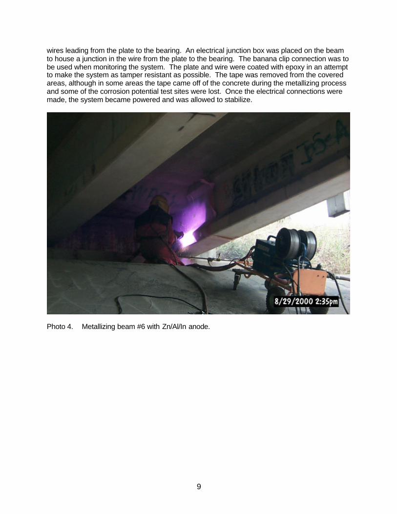
wires leading from the plate to the bearing. An electrical junction box was placed on the beamto house a junction in the wire from the plate to the bearing. The banana clip connection was tobe used when monitoring the system. The plate and wire were coated with epoxy in an attemptto make the system as tamper resistant as possible. The tape was removed from the coveredareas, although in some areas the tape came off of the concrete during the metallizing processand some of the corrosion potential test sites were lost. Once the electrical connections weremade, the system became powered and was allowed to stabilize.
Photo 4. Metallizing beam #6 with Zn/Al/In anode.

10
Photo 5. Expanded steel plate before second metallizing pass. Note loose tape on left.
Photo 6. Plate and wire covered with epoxy.

11
Results and Discussion of their Significance
A corrosion potential survey was conducted on the beams on October 31, 2001. Results of thesurvey were compared to the initial corrosion potential values obtained in the August 28, 2000pre-installation survey. The survey was conducted in accordance with ASTM C-876 the“Standard Test Method for Half-Cell Potentials of Uncoated Reinforcing Steel in Concrete.”Corrosion potentials were measured with a copper-copper sulfate half cell. Results arepresented in Table 2.

12
Test Location 1 2 3 4 5 6 7 8 A B C DBeam 1 8/28/00 -0.228 -0.025 0.075 0.102 0.128 0.070 -0.006 -0.277 0.125 0.069 0.023 -0.264
Zinc 10/31/01 -0.651 -0.076 -0.029 0.060 -0.001 -0.174 -0.228 NA -0.752 -0.144 -0.236 -0.334outside ? -0.423 -0.051 -0.104 -0.042 -0.129 -0.244 -0.222 NA -0.877 -0.213 -0.259 -0.070
8/28/00 -0.185 -0.002 0.062 0.125 0.143 0.115 0.048 -0.226inside 10/31/01 NA NA -0.046 -0.062 -0.230 -0.021 -0.300 -0.240
? NA NA -0.108 -0.187 -0.373 -0.136 -0.348 -0.014
Beam 2 8/28/00 -0.506 -0.492 -0.139 -0.111 -0.086 -0.128 -0.410 -0.497Zinc 10/31/01 NA -0.637 -0.048 -0.002 -0.054 -0.005 -0.040 NA
? NA -0.145 0.091 0.109 0.032 0.123 0.370 NA
Beam 3 8/28/00 -0.624 -0.449 -0.346 -0.332 -0.269 -0.287 -0.352 -0.464Zinc 10/31/01 -0.517 -0.167 -0.068 -0.039 -0.005 -0.001 -0.065 NA
? 0.107 0.282 0.278 0.293 0.264 0.286 0.287 NA
Beam 4 8/28/00 -0.657 -0.517 -0.241 -0.188 -0.177 -0.208 -0.404 -0.567Control 10/31/01 -0.581 -0.487 -0.213 -0.159 -0.162 -0.179 -0.373 -0.523
? 0.076 0.030 0.028 0.029 0.015 0.029 0.031 0.044
Beam 5 8/28/00 -0.415 -0.328 -0.061 0.003 -0.018 -0.059 -0.285 -0.394Control 10/31/01 -0.363 -0.295 0.010 0.035 0.023 0.010 -0.179 -0.319
? 0.052 0.033 0.071 0.032 0.041 0.069 0.106 0.075
Beam 6 8/28/00 -0.260 -0.112 0.097 0.154 0.202 0.166 -0.086 -0.150Zn/Al/Id 10/31/01 -0.652 -0.264 0.113 0.196 0.115 0.108 NA -0.286inside ? -0.392 -0.152 0.016 0.042 -0.087 -0.058 NA -0.136
outside 8/28/00 -0.192 0.021 0.110 0.098 0.120 0.098 0.037 -0.216 0.114 0.101 0.051 -0.15810/31/01 -0.402 -0.044 0.144 0.051 -0.001 -0.008 -0.242 -0.273 NA -0.008 -0.226 -0.272
? -0.210 -0.065 0.034 -0.047 -0.121 -0.106 -0.279 -0.057 NA -0.109 -0.277 -0.114Table 2. Corrosion Potential Survey Results.

13
Test Location 1 2 3 4 5 6 7 8 A B C DBeam 7 8/28/00 -0.247 0.039 0.094 0.107 0.125 0.082 -0.014 -0.273 0.115 0.077 -0.007 -0.259Zn/Al/Id 10/31/01 -0.393 -0.170 -0.111 -0.113 -0.165 -0.166 -0.227 -0.346 -0.068 NA -0.201 -0.330outside ? -0.146 -0.209 -0.205 -0.220 -0.290 -0.248 -0.213 -0.073 -0.183 NA -0.194 -0.071
inside 8/28/00 -0.239 -0.138 0.080 0.123 0.144 0.107 -0.146 -0.18510/31/01 -0.365 -0.509 -0.095 -0.059 -0.034 -0.058 -0.397 -0.347
? -0.126 -0.371 -0.175 -0.182 -0.178 -0.165 -0.251 -0.162
Beam 8 8/28/00 -0.476 -0.331 -0.135 -0.092 -0.085 -0.115 -0.300 -0.380Control 10/31/01 -0.418 -0.326 -0.096 -0.082 -0.081 -0.077 -0.260 -0.380
? 0.058 0.005 0.039 0.010 0.004 0.038 0.040 0.000
Beam 9 8/28/00 -0.210 -0.064 -0.027 -0.003 0.053 0.040 0.000 -0.124Control 10/31/01 -0.335 -0.176 -0.128 -0.093 -0.045 -0.043 -0.065 -0.192
? -0.125 -0.112 -0.101 -0.090 -0.098 -0.083 -0.065 -0.068
Beam 10 8/28/00 -0.258 -0.201 -0.185 -0.169 -0.141 -0.146 -0.131 -0.21085/15 Zn/Al 10/31/01 -0.084 -0.015 -0.051 -0.019 -0.032 0.008 -0.027 -0.004
? 0.174 0.186 0.134 0.150 0.109 0.154 0.104 0.206
Beam 11 8/28/00 -0.267 -0.208 -0.038 -0.004 0.041 -0.042 -0.199 -0.34785/15 Zn/Al 10/31/01 -0.852 -0.847 -0.605 NA -0.523 -0.625 -0.754 -0.889
? -0.585 -0.639 -0.567 NA -0.564 -0.583 -0.555 -0.542
Beam 12 8/28/00 -0.260 -0.130 -0.042 -0.031 0.008 -0.016 -0.104 -0.35785/15 Zn/Al 10/31/01 -0.278 -0.135 -0.063 -0.041 -0.037 -0.090 -0.043 NA
inside ? -0.018 -0.005 -0.021 -0.010 -0.045 -0.074 0.061 NA
outside 8/28/00 -0.303 -0.153 -0.073 -0.054 0.011 -0.089 -0.096 -0.374 -0.007 -0.081 -0.088 -0.31610/31/01 -0.337 -0.205 -0.063 -0.073 -0.704 -0.164 NA NA 0.033 -0.105 -0.137 NA
? -0.034 -0.052 0.010 -0.019 -0.715 -0.075 NA NA 0.040 -0.024 -0.049 NATable 2. Corrosion Potential Survey Results. (continued.)

14
Once the corrosion potentials were tabulated and compared to initial values, the following overallconclusions could be drawn about the performance of the anodes:
• None of the anodes displayed an improvement (reduction in the change of the corrosionpotential) when compared to the control beams to warrant additional testing.
• The corrosion potential at the test site was highly influenced by the location of the test siterelative to “available water.” This would include rain on the fascia beams, water from leakingjoints, or cracks in the bridge deck itself. In areas with more available water, the corrosionpotentials were much higher, indicating that the anode did not have enough driving power toovercome the corrosion process.
Results from individual beams are discussed below
Beams 1, 2 , and 3 were sprayed with an anode composed of 100% zinc. Beam 1 was a fasciabeam on the west-side of the west structure (SN 072-0116). Evaluation of the corrosionpotentials show values higher than those for the control beams (Beams 4 and 5) for that structure.Even though the outside of the beam was exposed to more water than other locations, corrosionpotentials for locations 2, 3, 4, 5, and D for beam 1 show values similar to those of the controlbeams, indicating that corrosion is more active at locations 1, 6, 7, B, and C. Location A is notconsidered valid and will be discussed later. Values for the inside of Beam 1 show corrosionpotentials higher than those of the control beams, somewhat in line with the same locations onthe outside of the beam. A higher rate of corrosion would be expected in a fascia beamcompared to the interior beams.
Values for Beams 2 and 3 show a higher rate of corrosion occurring at the bottom test locationsas opposed to those on top, as well as at locations closer to the end of the beams than further inthe beams. This is somewhat expected since water entering the beams from leaks in the jointswould collect at the exposed ends of the pre-stressing strands. More would tend to collect at thebottom of the beam than at the top as it ran down the web and collected at the exposed ends ofthe pre-stressing strands. Photo 7 shows evidence of zinc oxide (a corrosion product) forming onthe surface of the zinc anode where water has run down the surface of the beam.

15
Photo 7. Beam 2 west side Zn/Al anode corrosion products.
Beams 4 and 5 (control beams) show small changes in the corrosion potentials compared to theother beams, possibly due to the intact deck joint preventing water form migrating into the beams.The two beams show the least amount change in corrosion potentials compared to the treatedbeams. Photo 8 shows evidence of very little water running down the face of beam 4.
16
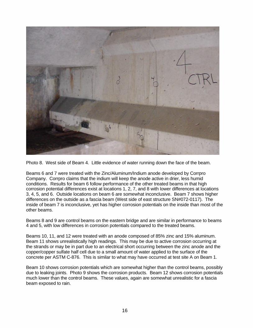
Photo 8. West side of Beam 4. Little evidence of water running down the face of the beam.
Beams 6 and 7 were treated with the Zinc/Aluminum/Indium anode developed by CorrproCompany. Corrpro claims that the indium will keep the anode active in drier, less humidconditions. Results for beam 6 follow performance of the other treated beams in that highcorrosion potential differences exist at locations 1, 2, 7, and 8 with lower differences at locations3, 4, 5, and 6. Outside locations on beam 6 are somewhat inconclusive. Beam 7 shows higherdifferences on the outside as a fascia beam (West side of east structure SN#072-0117). Theinside of beam 7 is inconclusive, yet has higher corrosion potentials on the inside than most of theother beams.
Beams 8 and 9 are control beams on the eastern bridge and are similar in performance to beams4 and 5, with low differences in corrosion potentials compared to the treated beams.
Beams 10, 11, and 12 were treated with an anode composed of 85% zinc and 15% aluminum.Beam 11 shows unrealistically high readings. This may be due to active corrosion occurring atthe strands or may be in part due to an electrical short occurring between the zinc anode and thecopper/copper sulfate half cell due to a small amount of water applied to the surface of theconcrete per ASTM C-876. This is similar to what may have occurred at test site A on Beam 1.
Beam 10 shows corrosion potentials which are somewhat higher than the control beams, possiblydue to leaking joints. Photo 9 shows the corrosion products. Beam 12 shows corrosion potentialsmuch lower than the control beams. These values, again are somewhat unrealistic for a fasciabeam exposed to rain.
17
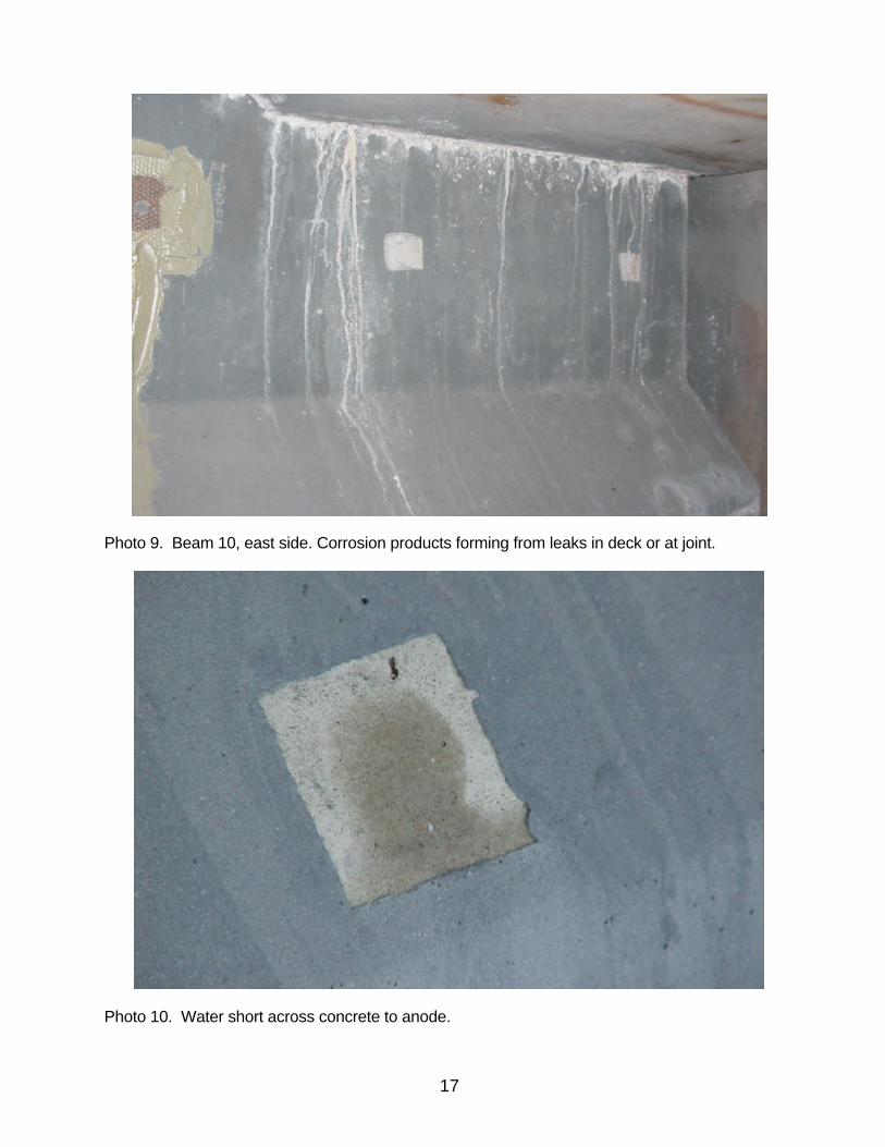
Photo 9. Beam 10, east side. Corrosion products forming from leaks in deck or at joint.
Photo 10. Water short across concrete to anode.
18
Conclusions and Recommendations
Evaluation of the three different types of “spray on” anodes for galvanic cathodic protectionindicate that the systems do not offer any improved amount of protection to the pre-stressingstrands when compared to beams that were not treated. Results from the corrosion potentialsurveys indicate that the systems are not protecting the steel. It appears that the anodes do notdevelop enough current necessary to drive the ion exchange to arrest the corrosion process. Anadditional survey is proposed for spring of 2002 to evaluate the anode performance. Severalenvironmental factors as well as equipment factors which may have affected the test results willbe evaluated. A main concern is the effect of water, used to moisten the surface of the concrete,bridging across the anode to form a localized short in the system. This will be addressed by usinga highly conductive multi-purpose electrolyte gel to ensure conductivity. Additionally, a smallerdiameter copper-copper sulfate half-cell will be evaluated to reduce the chances of bridgingacross the anode.
Presently, it appears that the anodes do not develop enough driving current to perform the ionexchange at the concrete-rebar interface. Until the current demand can be addressed, it wouldnot be beneficial to the Department to pursue additional galvanic cathodic protection research.