140 PSI twIn cylInder aIr comPreSSor PumP for 5 HP...
20
140 PSI TWIN CYLINDER AIR COMPRESSOR PUMP FOR 5 HP MOTOR Model 93786 SET UP AND OPERATING INSTRUCTIONS Visit our website at: http://www.harborfreight.com Read this material before using this product. Failure to do so can result in serious injury. SAVE THIS MANUAL. Copyright © 2009 by Harbor Freight Tools ® . All rights reserved. No portion of this manual or any artwork contained herein may be reproduced in any shape or form without the express written consent of Harbor Freight Tools. Diagrams within this manual may not be drawn proportionally. Due to continuing improvements, actual product may differ slightly from the product described herein. Tools required for assembly and service may not be included. For technical questions or replacement parts, please call 1-800-444-3353. Manual Revised 09i, 09k
Transcript of 140 PSI twIn cylInder aIr comPreSSor PumP for 5 HP...
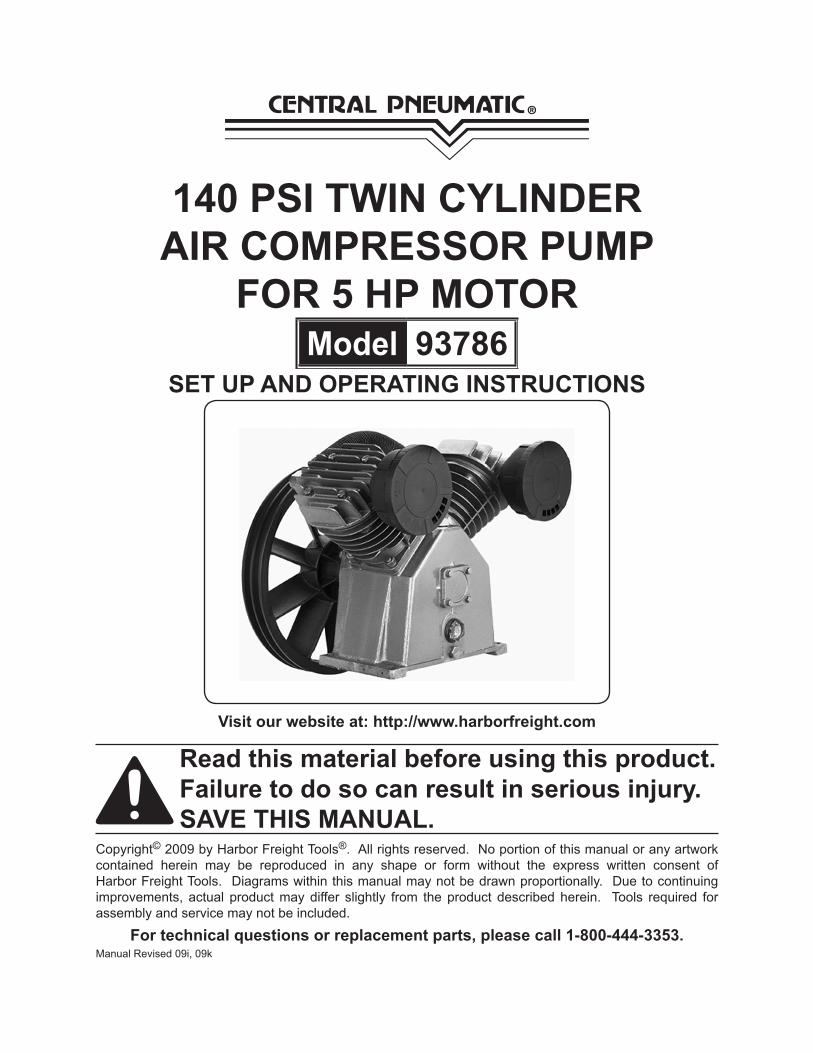
140 PSI twIn cylInder aIr comPreSSor PumP
for 5 HP motormodel 93786
Set uP and oPeratIng InStructIonS
Visit our website at: http://www.harborfreight.com
read this material before using this product. failure to do so can result in serious injury. SaVe tHIS manual.
Copyright© 2009 by Harbor Freight Tools®. All rights reserved. No portion of this manual or any artwork contained herein may be reproduced in any shape or form without the express written consent of Harbor Freight Tools. Diagrams within this manual may not be drawn proportionally. Due to continuing improvements, actual product may differ slightly from the product described herein. Tools required for assembly and service may not be included.
for technical questions or replacement parts, please call 1-800-444-3353.Manual Revised 09i, 09k
Page 2for technical questions, please call 1-800-444-3353.SKU 93786
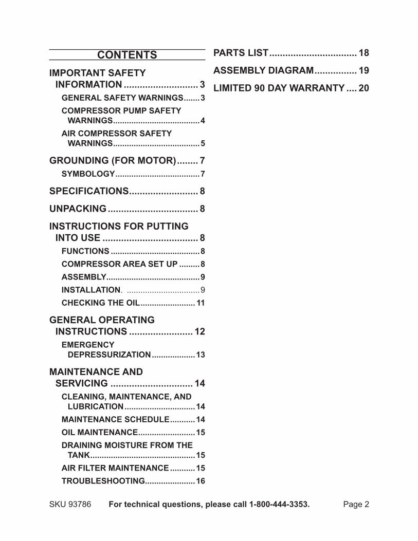
contentSImPortant Safety
InformatIon ............................ 3general Safety warnIngS .......3comPreSSor PumP Safety
warnIngS ......................................4aIr comPreSSor Safety
warnIngS ......................................5
groundIng (for motor) ........ 7Symbology .....................................7
SPecIfIcatIonS .......................... 8
unPackIng .................................. 8
InStructIonS for PuttIng Into uSe .................................... 8
functIonS .......................................8comPreSSor area Set uP .........8aSSembly.........................................9InStallatIon. ................................9cHeckIng tHe oIl ........................ 11
general oPeratIng InStructIonS ........................ 12
emergency dePreSSurIzatIon ...................13
maIntenance and SerVIcIng ............................... 14
cleanIng, maIntenance, and lubrIcatIon ...............................14
maIntenance ScHedule ...........14oIl maIntenance .........................15draInIng moISture from tHe
tank ..............................................15aIr fIlter maIntenance ...........15troubleSHootIng ......................16
PartS lISt ................................. 18
aSSembly dIagram ................ 19
lImIted 90 day warranty .... 20

Page 3for technical questions, please call 1-800-444-3353.SKU 93786
SaVe tHIS manualKeep this manual for the safety
warnings and precautions, assembly, operating, inspection, maintenance and cleaning procedures. Write the product’s serial number in the back of the manual near the assembly diagram (or month and year of purchase if product has no number). Keep this manual and the receipt in a safe and dry place for future reference.
ImPortant Safety InformatIon
In this manual, on the labeling, and all other information provided with this product:
this is the safety alert symbol. It is used to alert you to potential personal injury hazards. obey all safety messages that follow this symbol to avoid possible injury or death.
danger indicates a hazardous
situation which, if not avoided, will result in death or serious injury.
warnIng indicates a
hazardous situation which, if not avoided, could result in death or serious injury.
cautIon, used with the safety
alert symbol, indicates a hazardous situation which, if
not avoided, could result in minor or moderate injury.
notIce is used to address practices
not related to personal injury.
cautIon, without the safety alert
symbol, is used to address practices not related to personal injury.
general Safety warnings warnIng read all safety warnings and instructions. Failure to follow the warnings and instructions may result in electric shock, fire and/or serious injury. Save all warnings and instructions for future reference.
work area safety1. keep work area clean and well a. lit. Cluttered or dark areas invite accidents.do not operate the compressor b. Pump in explosive atmospheres, such as in the presence of flammable liquids, gases or dust. Compressor motors produce sparks which may ignite the dust or fumes.keep children and bystanders c. away from an operating compressor pump.
Personal safety2. Stay alert, watch what you are a. doing and use common sense when operating this compressor pump. do not use this compressor pump while you are tired or under the influence of drugs, alcohol or medication. A moment of inattention
REV 09j
Page 4for technical questions, please call 1-800-444-3353.SKU 93786
while operating a compressor pump may result in serious personal injury.use personal protective b. equipment. always wear eye protection. Safety equipment such as a dust mask, non-skid safety shoes, hard hat, or hearing protection used for appropriate conditions will reduce personal injuries. only use safety equipment c. that has been approved by an appropriate standards agency. Unapproved safety equipment may not provide adequate protection. Eye protection must be ANSI-approved and breathing protection must be NIOSH-approved for the specific hazards in the work area.
compressor Pump use and care3. do not use the unit if its power a. switch does not turn it on and off. Any tool that cannot be controlled with its power switch is dangerous and must be repaired.disconnect the plug from the b. power source before making any adjustments, changing accessories, or storing the compressor pump. Such preventive safety measures reduce the risk of starting the unit accidentally.Store an idle compressor pump c. out of the reach of children and do not allow persons unfamiliar with the compressor pump or these instructions to operate it. A compressor pump is dangerous in the hands of untrained users.maintain the compressor pump. d. keep the compressor pump clean for better and safer performance. follow instructions for lubricating
and changing accessories. keep the outside surfaces dry, clean and free from oil and grease. check for misalignment or binding of moving parts, breakage of parts and any other condition that may affect the compressor pump’s operation. If damaged, have the compressor pump repaired before use. Many accidents are caused by a poorly maintained compressor pump.use the compressor pump e. in accordance with these instructions, taking into account the working conditions and the work to be performed. Use of the compressor pump for operations different from those intended could result in a hazardous situation.
Service4. Have your compressor pump a. serviced by a qualified repair person using only identical replacement parts. This will ensure that the safety of the compressor pump is maintained.
compressor Pump Safety warnings
Wear ANSI-approved safety goggles 1. during use.
Install pulley and belt safety guard 2. before use.
Before first and every use, verify 3. Pump has sufficient oil.
The use of accessories or 4. attachments not recommended by the manufacturer may result in a risk of injury to persons.
REV 09j
Page 5for technical questions, please call 1-800-444-3353.SKU 93786
misalignment between motor 5. and Pump can damage the belt wheel. Use a straight edge, such as a yardstick, to check and adjust alignment as needed.
use proper size motor and motor 6. pulley. This air compressor Pump must be installed with a 3 HP electric motor and pulley (both not supplied) which can turn the Air Compressor Belt Wheel at approximately 1050 rpm, but not more than 1200 rpm.
Install motor, pulley belt and pulley 7. belt cover securely. Be sure to use the proper size bolts to install your motor (not included). The belt and belt cover (not included) must be strong enough to prevent breaking and possible injury.
be sure all equipment is rated to 8. the appropriate capacity of this pump. Make sure that the lowest rated piece of equipment you are using can handle the maximum pressure of the Air Compressor Pump (see Specifications).
do not direct the air outlet at any 9. person or animal.
use Safety guard for Pulleys.10. The Air Compressor Belt Wheel (35), V-belt (not supplied), and motor pulley (not supplied) must be covered by a safety guard (not supplied) covering all moving elements before operation.
avoid burns. 11. The Cylinder (12), Cylinder Head (5) and Air Outlet (6) become very hot during operation. Do not touch.
air compressor Safety warningsRisk of fire or explosion - Do not 1. spray flammable liquid in a confined area or towards a hot surface. Spray area must be well-ventilated. Do not smoke while spraying or spray where spark or flame is present. Arcing parts - Keep compressor at least 20 feet away from explosive vapors, such as when spraying with a spray gun.
Risk of bursting - Do not adjust 2. regulator higher than stated maximum pressure of attachment.
Risk of injury - Do not direct air 3. stream at people or animals.
To reduce the risk of electric shock, 4. do not expose to rain. Store indoors.
Wear ANSI-approved safety goggles 5. during use.
Do not use to supply breathing air. 6.
Drain Tank daily and after use. 7. Internal rust causes tank failure and explosion.
Add correct amount of compressor 8. oil before first use and every use. Operating with low or no oil causes permanent damage and voids warranty.
Do not remove the valve cover or 9. adjust internal components.
Do not use the air hose to move the 10. compressor.
Release the pressure in the storage 11. tank before moving.
The use of accessories or 12. attachments not recommended by
REV 09j
Page 6for technical questions, please call 1-800-444-3353.SKU 93786
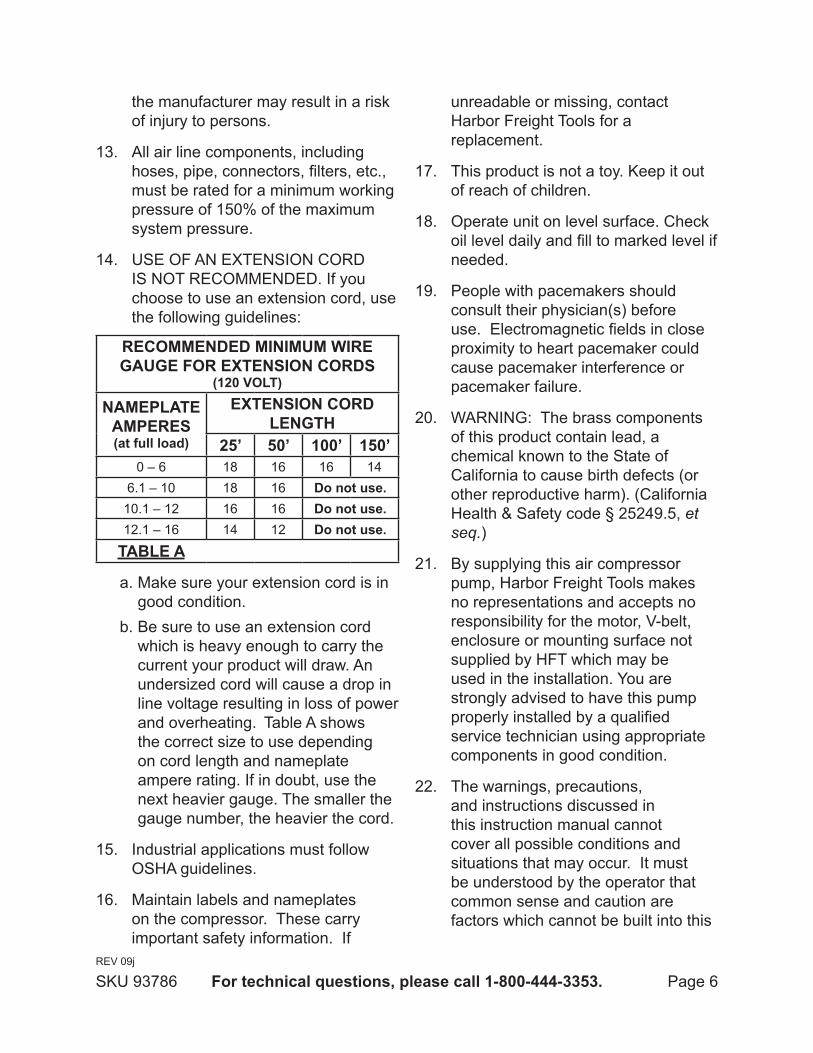
the manufacturer may result in a risk of injury to persons.
All air line components, including 13. hoses, pipe, connectors, filters, etc., must be rated for a minimum working pressure of 150% of the maximum system pressure.
USE OF AN EXTENSION CORD 14. IS NOT RECOMMENDED. If you choose to use an extension cord, use the following guidelines:
recommended mInImum wIre gauge for eXtenSIon cordS
(120 Volt)
namePlate amPereS(at full load)
eXtenSIon cord lengtH
25’ 50’ 100’ 150’0 – 6 18 16 16 14
6.1 – 10 18 16 do not use.10.1 – 12 16 16 do not use.12.1 – 16 14 12 do not use.
table a
Make sure your extension cord is in a. good condition. Be sure to use an extension cord b. which is heavy enough to carry the current your product will draw. An undersized cord will cause a drop in line voltage resulting in loss of power and overheating. Table A shows the correct size to use depending on cord length and nameplate ampere rating. If in doubt, use the next heavier gauge. The smaller the gauge number, the heavier the cord.
Industrial applications must follow 15. OSHA guidelines.
Maintain labels and nameplates 16. on the compressor. These carry important safety information. If
unreadable or missing, contact Harbor Freight Tools for a replacement.
This product is not a toy. Keep it out 17. of reach of children.
Operate unit on level surface. Check 18. oil level daily and fill to marked level if needed.
People with pacemakers should 19. consult their physician(s) before use. Electromagnetic fields in close proximity to heart pacemaker could cause pacemaker interference or pacemaker failure.
WARNING: The brass components 20. of this product contain lead, a chemical known to the State of California to cause birth defects (or other reproductive harm). (California Health & Safety code § 25249.5, et seq.)
By supplying this air compressor 21. pump, Harbor Freight Tools makes no representations and accepts no responsibility for the motor, V-belt, enclosure or mounting surface not supplied by HFT which may be used in the installation. You are strongly advised to have this pump properly installed by a qualified service technician using appropriate components in good condition.
The warnings, precautions, 22. and instructions discussed in this instruction manual cannot cover all possible conditions and situations that may occur. It must be understood by the operator that common sense and caution are factors which cannot be built into this
REV 09j
Page 7for technical questions, please call 1-800-444-3353.SKU 93786
product, but must be supplied by the operator.
SaVe tHeSe InStructIonS.
groundIng (for motor) to PreVent
electrIc SHock and deatH from Incorrect groundIng wIre connectIon: Check with a qualified electrician if you are in doubt as to whether the outlet is properly grounded. do not modify the power cord plug provided with the motor. never remove the grounding prong from the plug. do not use the motor if the power cord or plug is damaged. If damaged, have it repaired by a service facility before use. If the plug will not fit the outlet, have a proper outlet installed by a qualified electrician.
Symbology
Double Insulated
Canadian Standards Association
Underwriters Laboratories, Inc.
V~ Volts Alternating Current
a Amperes
n0 xxxx/min. No Load Revolutions per Minute (RPM)
REV 09j
Page 8for technical questions, please call 1-800-444-3353.SKU 93786
SPecIfIcatIonS
Compressor Type Single Stage Twin Cylinder
Maximum Air Pressure 140 PSI
Maximum Speed 1200 RPM
Outlet 3/4” x 14-TPI
Air Delivery (@ 1050 RPM)
18 SCFM @ 40 PSI13.4 SCFM @ 90 PSI12.3 SCFM @ 115 PSI
Lubrication Splash Type with Oil Level Window
Oil Type
SAE 30W non-detergentAir Compressor Oil(Sold separately)(SKU 95048)
Belt Wheel14-1/2” dia. x 1-51/64” with dual V-groove for two belts
Belt Type Two B Type
Mounting Hole Pattern 5-1/4” x 10-1/4” (center to center)
Recommended Mounting Brackets 1/2” x 14 TPI
Overall Dimensions 14-1/2”H x 17-3/4” W x 11-3/4”D
unPackIngWhen unpacking, make sure that the
item is intact and undamaged. If any parts are missing or broken, please call Harbor Freight Tools at 1-800-444-3353 as soon as possible.
InStructIonS for PuttIng Into uSe read the entIre ImPortant
Safety InformatIon section at the beginning of this manual including all text under subheadings therein before set up or use of this product.
to PreVent SerIouS Injury
from accIdental oPeratIon: turn off and unplug the motor before assembling or making any adjustments to the motor, tank, and/or compressor pump.
note: For additional information regarding the parts listed in the following pages, refer to the Assembly Diagram near the end of this manual.
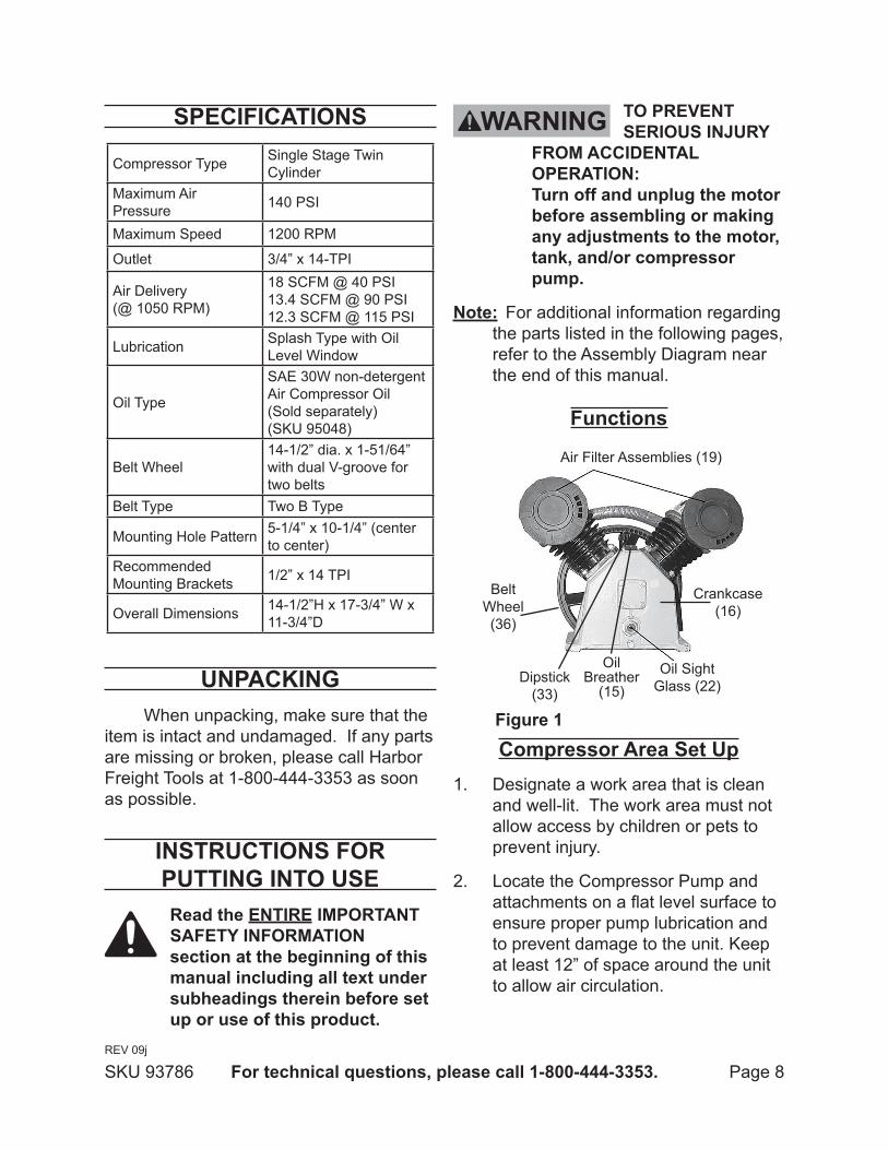
functions
Oil Sight Glass (22)
Air Filter Assemblies (19)
Belt Wheel (36)
Crankcase (16)
Dipstick (33)
Oil Breather
(15)
figure 1
compressor area Set upDesignate a work area that is clean 1. and well-lit. The work area must not allow access by children or pets to prevent injury.
Locate the Compressor Pump and 2. attachments on a flat level surface to ensure proper pump lubrication and to prevent damage to the unit. Keep at least 12” of space around the unit to allow air circulation.
REV 09j
Page 9for technical questions, please call 1-800-444-3353.SKU 93786
Route the power cord from the motor 3. to the grounded wall outlet, along a safe path without creating a tripping hazard or exposing the power cord to possible damage.
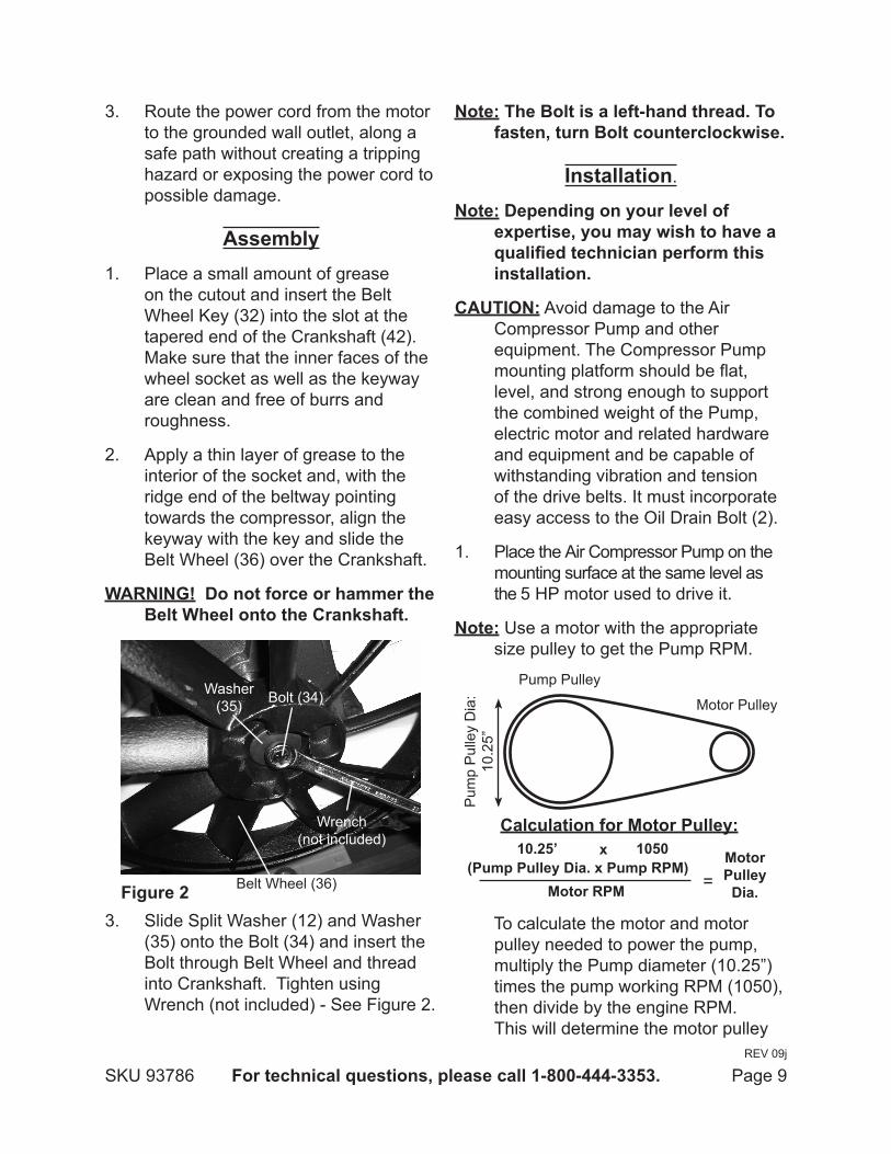
assemblyPlace a small amount of grease 1. on the cutout and insert the Belt Wheel Key (32) into the slot at the tapered end of the Crankshaft (42). Make sure that the inner faces of the wheel socket as well as the keyway are clean and free of burrs and roughness.
Apply a thin layer of grease to the 2. interior of the socket and, with the ridge end of the beltway pointing towards the compressor, align the keyway with the key and slide the Belt Wheel (36) over the Crankshaft.
warnIng! do not force or hammer the belt wheel onto the crankshaft.
Bolt (34)Washer (35)
figure 2
Wrench (not included)
Belt Wheel (36)
3. Slide Split Washer (12) and Washer (35) onto the Bolt (34) and insert the Bolt through Belt Wheel and thread into Crankshaft. Tighten using Wrench (not included) - See Figure 2.
note: the bolt is a left-hand thread. to fasten, turn bolt counterclockwise.
Installation.
note: depending on your level of expertise, you may wish to have a qualified technician perform this installation.
cautIon: Avoid damage to the Air Compressor Pump and other equipment. The Compressor Pump mounting platform should be flat, level, and strong enough to support the combined weight of the Pump, electric motor and related hardware and equipment and be capable of withstanding vibration and tension of the drive belts. It must incorporate easy access to the Oil Drain Bolt (2).
Place the Air Compressor Pump on the 1. mounting surface at the same level as the 5 HP motor used to drive it.
note: Use a motor with the appropriate size pulley to get the Pump RPM.
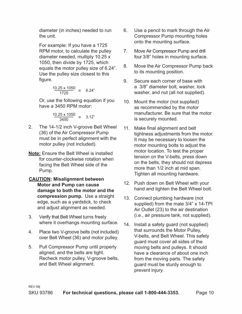
calculation for motor Pulley:
Motor Pulley
Pump Pulley
Pum
p P
ulle
y D
ia:
10.2
5”
(Pump Pulley dia. x Pump rPm)motor rPm
10.25’ 1050
=motor Pulley dia.
x
To calculate the motor and motor pulley needed to power the pump, multiply the Pump diameter (10.25”) times the pump working RPM (1050), then divide by the engine RPM. This will determine the motor pulley
REV 09j
Page 10for technical questions, please call 1-800-444-3353.SKU 93786
diameter (in inches) needed to run the unit.
For example: If you have a 1725 RPM motor, to calculate the pulley diameter needed, multiply 10.25 x 1050, then divide by 1725, which equals the motor pulley size of 6.24”. Use the pulley size closest to this figure.
10.25 x 10501725 = 6.24”
Or, use the following equation if you have a 3450 RPM motor:
10.25 x 10503450 = 3.12”
2. The 14-1/2 inch V-groove Belt Wheel (36) of the Air Compressor Pump must be in perfect alignment with the motor pulley (not included).
note: Ensure the Belt Wheel is installed for counter-clockwise rotation when facing the Belt Wheel side of the Pump.
cautIon: misalignment between motor and Pump can cause damage to both the motor and the compression pump. Use a straight edge, such as a yardstick, to check and adjust alignment as needed.
Verify that Belt Wheel turns freely 3. where it overhangs mounting surface.
Place two V-groove belts (not included) 4. over Belt Wheel (36) and motor pulley.
Pull Compressor Pump until properly 5. aligned, and the belts are tight. Recheck motor pulley, V-groove belts, and Belt Wheel alignment.
Use a pencil to mark through the Air 6. Compressor Pump mounting holes onto the mounting surface.
Move Air Compressor Pump and drill 7. four 3/8” holes in mounting surface.
Move the Air Compressor Pump back 8. to its mounting position.
Secure each corner of base with 9. a 3/8” diameter bolt, washer, lock washer, and nut (all not supplied).
Mount the motor (not supplied) 10. as recommended by the motor manufacturer. Be sure that the motor is securely mounted.
Make final alignment and belt 11. tightness adjustments from the motor. It may be necessary to loosen the motor mounting bolts to adjust the motor location. To test the proper tension on the V-belts, press down on the belts, they should not depress more than 1/2 inch at mid span. Tighten all mounting hardware.
Push down on Belt Wheel with your 12. hand and tighten the Belt Wheel bolt.
Connect plumbing hardware (not 13. supplied) from the male 3/4” x 14-TPI Air Outlet (23) to the air destination (i.e., air pressure tank, not supplied).
Install a safety guard (not supplied) 14. that surrounds the Motor Pulley, V-belts, and Belt Wheel. This safety guard must cover all sides of the moving belts and pulleys. It should have a clearance of about one inch from the moving parts. The safety guard must be sturdy enough to prevent injury.
REV 09j

Page 11for technical questions, please call 1-800-444-3353.SKU 93786
note: A qualified electrician must wire in a pressure switch control that turns off the motor when the pump reaches the desired pressure (145 PSI or less).
note: Always install Air Compressor Pump to air tank that can withstand at least 145 PSI and has a safety valve.
note: A high/low cut-in/cut-out switch (not included) can be incorporated to operate a motor starter or motor contractor for semi-automatic control of air pressure in the vessel.
warnIng! Avoid serious injuries. Do not operate this Air Compressor Pump without a pulley guard in place.
Using the above diagram as a guide,15.
Quick coupler
Sample air line Setup
regulator with Pressure gauge
Quick coupler air Hose
on reel
Shut off
Valvefilteroiler
coupler Plug
tool
air compressor
coupler Plug
connect a regulator valve, an inline shut off valve and a 1/4” NPT air hose to the Quick Coupler (all sold separately). The air hose must be long enough to reach the work area with enough extra length to allow free movement while working.
note: an in-line shutoff ball valve is an important safety device because it controls the air supply even if the air hose is ruptured. the shutoff valve should be a ball valve because it can be closed quickly.
Depending on the tool which you will 16. be using with this compressor, you may need to incorporate additional components, such as an in-line oiler, a filter, or a dryer. Consult your air tool’s manual for needed accessories.
checking the oilCheck the oil level before operation. Fill the Pump Crankcase with SAE 30W non-detergent air compressor oil (sold separately).
ImPortant: running the air compressor Pump with no oil or low oil will cause damage to the equipment and void the warranty.
Oil Sight Glass (4)
Crankcase (1)
oVerfIll
low
full
OIL LEVEL
figure 2The oil level should be at the center of the “full” level on the oil level sight glass, as shown in Figure 2 above. Add oil as needed to maintain this level. Do not let the oil level go below the center dot (LOW as shown above) and do not overfill the oil
REV 09j
Page 12for technical questions, please call 1-800-444-3353.SKU 93786
so that it is above the center dot (OVERFILL as shown above) on the sight glass.
To add oil:Remove the Oil Plug.a. Using a funnel to avoid spills, pour b. enough oil into the Pump Crankcase to reach the “full” level in the Oil Sight Glass.Replace the Oil Plug.c.
note: SAE 30W non-detergent Air Compressor Oil (sold separately) is recommended for use with this pump.
If uncertain which oil to use, please call Harbor Freight Tools customer service at 1-800-444-3353 for assistance.
change the compressor oil after the first hour of use to remove any debris.
warnIng! To prevent serious injury from burns: Do not add or change the oil while the motor is in operation. Allow the components to cool before replacing oil.
general oPeratIng InStructIonS
read the entIre ImPortant Safety InformatIon section at the beginning of this manual including all text under subheadings therein before set up or use of this product.
Close the Drain Valve.1.
Make sure all nuts and bolts are tight.2.
Check for oil leaks and check the oil 3. level (See Checking the Oil).
Close the in-line Shutoff Valve 4. between the compressor and the air hose.
Make sure the air tool’s throttle or 5. switch is in the off position.
Connect the air tool to the air hose. 6.
Plug the Air Compressor Power Cord 7. into a grounded 120 V electrical outlet.
Open the in-line Shutoff Valve.8.
Turn the Power Switch ON. 9.
Allow the Air Compressor to build up 10. pressure until it cycles off.
Check that the V-belt does not vibrate 11. and listen for abnormal noise or vibration.
If there is a problem, turn power off 12. and release air pressure from the line before attempting repairs.
note: At the beginning of the day’s first use of the Air Compressor, check for air leaks by applying soapy water to connections while the Air Compressor is pumping and after pressure cut-out. Look for air bubbles. If air bubbles are present at connections, tighten connections. Do not use the air compressor unless all connections are air tight, the extra air leaking out will cause the compressor to operate too often, increasing wear on the compressor.
note: As long as the Power Switch is ON, the operation of the Air Compressor is automatic, controlled by an internal pressure switch. The Compressor
REV 09j
Page 13for technical questions, please call 1-800-444-3353.SKU 93786
will turn on automatically when the air pressure drops to the minimum PSI as indicated on the Pressure Gauge, and will turn off automatically when the air pressure reaches the maximum PSI as indicated. ImPortant: The internal pressure switch is not user adjustable, do not make changes to the air pressure settings of the internal pressure switch. Any change to the automatic pressure levels may cause excess pressure to accumulate, causing a hazardous situation.
Adjust the Air Compressor’s Pressure 13. Regulator so that the air output is enough to properly power the tool, but the output will not exceed the tool’s maximum air pressure at any time. Turn the knob clockwise to increase the pressure and counter-clockwise to decrease pressure. Adjust the pressure gradually, while checking the air output gauge to set the pressure.
Use the air tool as needed.14.
After the job is complete, turn the 15. Power Switch OFF.
Unplug the Air Compressor.16.
Close the in-line Shutoff Valve.17.
Bleed air from the tool then 18. disconnect the tool.
Turn the Drain Valve, at the bottom 19. of the Tank, two turns to release any built-up moisture and the internal tank pressure. Close the valve after moisture has drained out. Do not remove the Drain Valve.
Clean, then store the Air Compressor 20. indoors.
emergency depressurizationIf it is necessary to quickly depressurize the tank, turn the motor OFF. Then, pull the Safety Valve to quickly release stored air pressure.
Page 14for technical questions, please call 1-800-444-3353.SKU 93786
maIntenance and SerVIcIng
Procedures not specifically explained in this manual must be performed only by a qualified technician.
to PreVent SerIouS Injury
from accIdental oPeratIon: turn off and unplug the motor before performing any inspection, maintenance, or cleaning procedures.
to PreVent SerIouS Injury from motor faIlure: do not use damaged equipment. If abnormal noise or vibration occurs, have the problem corrected before further use.
cleaning, maintenance, and lubrication
before eacH uSe,1. inspect the general condition of the unit. Check for loose hardware, misalignment or binding of moving parts, damaged belts, cracked or broken parts, damaged electrical wiring, and any other condition that may affect its safe operation.
after uSe,2. wipe external surfaces of the unit with a clean cloth.
3. warnIng! If the supply cord of this unit is damaged, it must be replaced only by a qualified service technician.
maintenance ScheduleFollowing are general guidelines for maintenance checks of the unit.
note: The working environment and frequency of use can affect how often you will need to check components and perform maintenance procedures.
daily:Check oil level.a. Check for oil leaks.b. Make sure all nuts and bolts are c. tight.Drain moisture from air tank.d. Check for abnormal noise or e. vibration.Check for air leaks.f. *
Inspect belt.g. Wipe off any oil or dirt from the h. components.**
weekly:Inspect Air Filter.a. Inspect Oil Breather Plug (15).b.
monthly:Inspect Safety Valve.a. Check belt adjustment.b.
every 6 months or 100 operation Hours:
Replace Pump oil.***
* To check for air leaks, apply soapy water to joints while the tank is pressurized. Look for air bubbles.** To clean the unit, wipe with a damp cloth, using a mild detergent or mild solvent.*** Use Air Compressor Oil only (sold separately - SKU 95048).
REV 09j
Page 15for technical questions, please call 1-800-444-3353.SKU 93786
oil maintenanceCheck the oil periodically for clarity. Replace oil if it appears milky or if debris is present, or every 6 months, or 100 hours of runtime, whichever comes first. In harsh environments such as high heat or high humidity, you will need to replace the oil more frequently.
warnIng: Risk of personal injury hazard. Allow Air Compressor to cool before changing the oil.
to drain the oil from the Pump crankcase:
Place a container under the Oil Drain a. Bolt (24). Remove the Oil Breather (15) to b. allow air flow into the Pump.Remove the Oil Drain Bolt, allowing c. the oil to drain into the container.When the oil is completely drained d. from the Pump, replace the Oil Drain Bolt.Fill the Pump with new compressor e. oil to the FULL level on the Oil Sight Glass.Replace and tighten the Oil Breather.f. Discard the old oil according to local, g. state and federal regulations.
draining moisture from the tankThe Drain Valve is located under the Tank. It must be accessed daily to release all trapped air and moisture from the Tank. This will eliminate condensation which can cause tank corrosion.
note: Do not open the Drain Valve so that more than four threads are showing.
To empty the air and condensation:Make sure the Power switch of the a. compressor is off.Place a collection pan under the b. Drain Valve.Unthread the Drain Valve two or c. three turns ONLY.When all the pressure and moisture d. is released, close the Drain Valve.
air filter maintenanceCheck the Air Filter weekly to see if it needs replacement. If working in dirty environments, you may need to replace the filter more often. To replace the Air Filter:Remove any cover that blocks a. access to the Air Filter.Remove the Air Filter.b. Replace with a new Air Filter.c. Replace the cover.d.
REV 09j

Page 16for technical questions, please call 1-800-444-3353.SKU 93786
troubleshootingProblem Possible causes likely Solutions
Compressor does not start or restart
Incorrect power supply.1. No power at outlet. 2.
Power cord not plugged in 3. properly.Thermal overload switch 4. tripped.Building power supply circuit 5. tripped or blown fuse.
Tanks are pressurized.6. Cord wire size is too small or 7. cord is too long to properly power compressor.Compressor needs service.8.
Check that circuit matches compressor requirements.1. Reset circuit breaker, or have outlet serviced by a 2. qualified technician.Check that cord is plugged in securely. 3.
Turn off Tool. Turn off Compressor and wait for it to 4. cool down. Press reset button. Resume operation.Reset circuit or replace fuse. Check for low voltage 5. conditions. It may be necessary to disconnect other electrical appliances from the circuit or move the compressor to its own circuit.Fully bleed tanks of air.6. Use larger diameter or shorter extension cord or 7. eliminate extension cord. See Recommended Wire Gauge for Extension Cords in Safety section.Have unit inspected by a qualified technician.8.
Compressor builds pressure too slowly
Incorrect power supply.1. Crankcase overfilled with oil or 2. oil too thick.Working environment too cold. 3.
Safety valve needs service. 4.
Loose fittings.5.
Check that circuit matches compressor requirements.1. Drain oil and refill to proper level with recommended 2. oil.Move unit to a warmer location. Check that 3. recommended oil is in crankcase.Listen for air leaking from valve. If leaking 4. replace with identical valve with same rating. Reduce air pressure, then check all fittings with a soap 5. solution for air leaks and tighten as needed. Do not overtighten.
Compressor not building enough air pressure
Filters need cleaning/replacing. 1.
Crankcase oil too thick. 2.
Check Valve needs service.3. Compressor not large enough 4. for job.
Loose fittings. 5.
Hose or hose connections not 6. adequate.High altitude reducing air 7. output.
Check inlet and outlet filters. Clean and/or replace as 1. needed.Drain oil and refill to proper level with recommended 2. oil. Clean or replace, as needed.3. Check if accessory SCFM is met by Compressor. If 4. Compressor cannot supply enough air flow (SCFM), you need a larger Compressor.Reduce air pressure, then check all fittings with a soap 5. solution for air leaks and tighten as needed. Do not overtighten.Replace with larger hose and/or hose connections. 6.
You may need a larger compressor if you are situated 7. in a high altitude location.
High Oil Consumption
Crankcase oil too thin. 1.
Unit not on level surface.2. Crankcase vent clogged.3.
Drain oil and refill to proper level with recommended 1. oil.Reposition unit on a level surface.2. Clean Crankcase vent.3.
follow all safety precautions whenever diagnosing or servicing the compressor. disconnect power supply before service.
REV 09j
Page 17for technical questions, please call 1-800-444-3353.SKU 93786
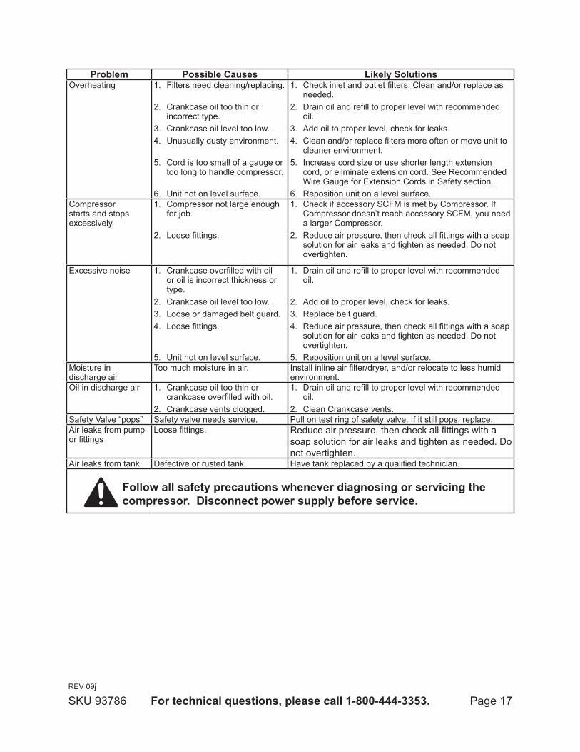
Problem Possible causes likely SolutionsOverheating Filters need cleaning/replacing. 1.
Crankcase oil too thin or 2. incorrect type.Crankcase oil level too low.3. Unusually dusty environment. 4.
Cord is too small of a gauge or 5. too long to handle compressor.
Unit not on level surface.6.
Check inlet and outlet filters. Clean and/or replace as 1. needed.Drain oil and refill to proper level with recommended 2. oil.Add oil to proper level, check for leaks.3. Clean and/or replace filters more often or move unit to 4. cleaner environment.Increase cord size or use shorter length extension 5. cord, or eliminate extension cord. See Recommended Wire Gauge for Extension Cords in Safety section.Reposition unit on a level surface.6.
Compressor starts and stops excessively
Compressor not large enough 1. for job.
Loose fittings.2.
Check if accessory SCFM is met by Compressor. If 1. Compressor doesn’t reach accessory SCFM, you need a larger Compressor.Reduce air pressure, then check all fittings with a soap 2. solution for air leaks and tighten as needed. Do not overtighten.
Excessive noise Crankcase overfilled with oil 1. or oil is incorrect thickness or type.Crankcase oil level too low.2. Loose or damaged belt guard.3. Loose fittings. 4.
Unit not on level surface.5.
Drain oil and refill to proper level with recommended 1. oil.
Add oil to proper level, check for leaks.2. Replace belt guard.3. Reduce air pressure, then check all fittings with a soap 4. solution for air leaks and tighten as needed. Do not overtighten.Reposition unit on a level surface.5.
Moisture in discharge air
Too much moisture in air. Install inline air filter/dryer, and/or relocate to less humid environment.
Oil in discharge air Crankcase oil too thin or 1. crankcase overfilled with oil.Crankcase vents clogged.2.
Drain oil and refill to proper level with recommended 1. oil.Clean Crankcase vents.2.
Safety Valve “pops” Safety valve needs service. Pull on test ring of safety valve. If it still pops, replace.Air leaks from pump or fittings
Loose fittings. Reduce air pressure, then check all fittings with a soap solution for air leaks and tighten as needed. Do not overtighten.
Air leaks from tank Defective or rusted tank. Have tank replaced by a qualified technician.
follow all safety precautions whenever diagnosing or servicing the compressor. disconnect power supply before service.
REV 09j
Page 18for technical questions, please call 1-800-444-3353.SKU 93786
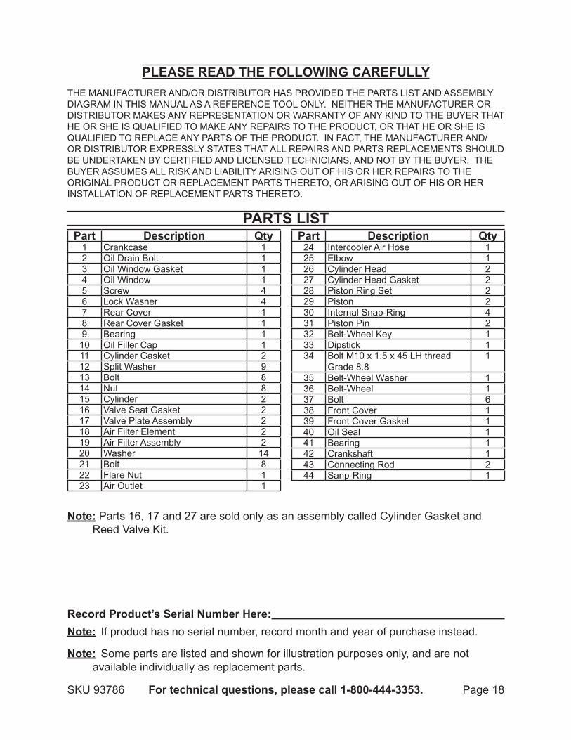
Part description Qty1 Crankcase 12 Oil Drain Bolt 13 Oil Window Gasket 14 Oil Window 15 Screw 46 Lock Washer 47 Rear Cover 18 Rear Cover Gasket 19 Bearing 1
10 Oil Filler Cap 111 Cylinder Gasket 212 Split Washer 913 Bolt 814 Nut 815 Cylinder 216 Valve Seat Gasket 217 Valve Plate Assembly 218 Air Filter Element 219 Air Filter Assembly 220 Washer 1421 Bolt 822 Flare Nut 123 Air Outlet 1
Part description Qty24 Intercooler Air Hose 125 Elbow 126 Cylinder Head 227 Cylinder Head Gasket 228 Piston Ring Set 229 Piston 230 Internal Snap-Ring 431 Piston Pin 232 Belt-Wheel Key 133 Dipstick 134 Bolt M10 x 1.5 x 45 LH thread
Grade 8.81
35 Belt-Wheel Washer 136 Belt-Wheel 137 Bolt 638 Front Cover 139 Front Cover Gasket 140 Oil Seal 141 Bearing 142 Crankshaft 143 Connecting Rod 244 Sanp-Ring 1
PleaSe read tHe followIng carefullyTHE MANUFACTURER AND/OR DISTRIBUTOR HAS PROVIDED THE PARTS LIST AND ASSEMBLY DIAGRAM IN THIS MANUAL AS A REFERENCE TOOL ONLY. NEITHER THE MANUFACTURER OR DISTRIBUTOR MAKES ANY REPRESENTATION OR WARRANTY OF ANY KIND TO THE BUYER THAT HE OR SHE IS QUALIFIED TO MAKE ANY REPAIRS TO THE PRODUCT, OR THAT HE OR SHE IS QUALIFIED TO REPLACE ANY PARTS OF THE PRODUCT. IN FACT, THE MANUFACTURER AND/OR DISTRIBUTOR EXPRESSLY STATES THAT ALL REPAIRS AND PARTS REPLACEMENTS SHOULD BE UNDERTAKEN BY CERTIFIED AND LICENSED TECHNICIANS, AND NOT BY THE BUYER. THE BUYER ASSUMES ALL RISK AND LIABILITY ARISING OUT OF HIS OR HER REPAIRS TO THE ORIGINAL PRODUCT OR REPLACEMENT PARTS THERETO, OR ARISING OUT OF HIS OR HER INSTALLATION OF REPLACEMENT PARTS THERETO.
PartS lISt
record Product’s Serial number Here: note: If product has no serial number, record month and year of purchase instead.
note: Some parts are listed and shown for illustration purposes only, and are not available individually as replacement parts.
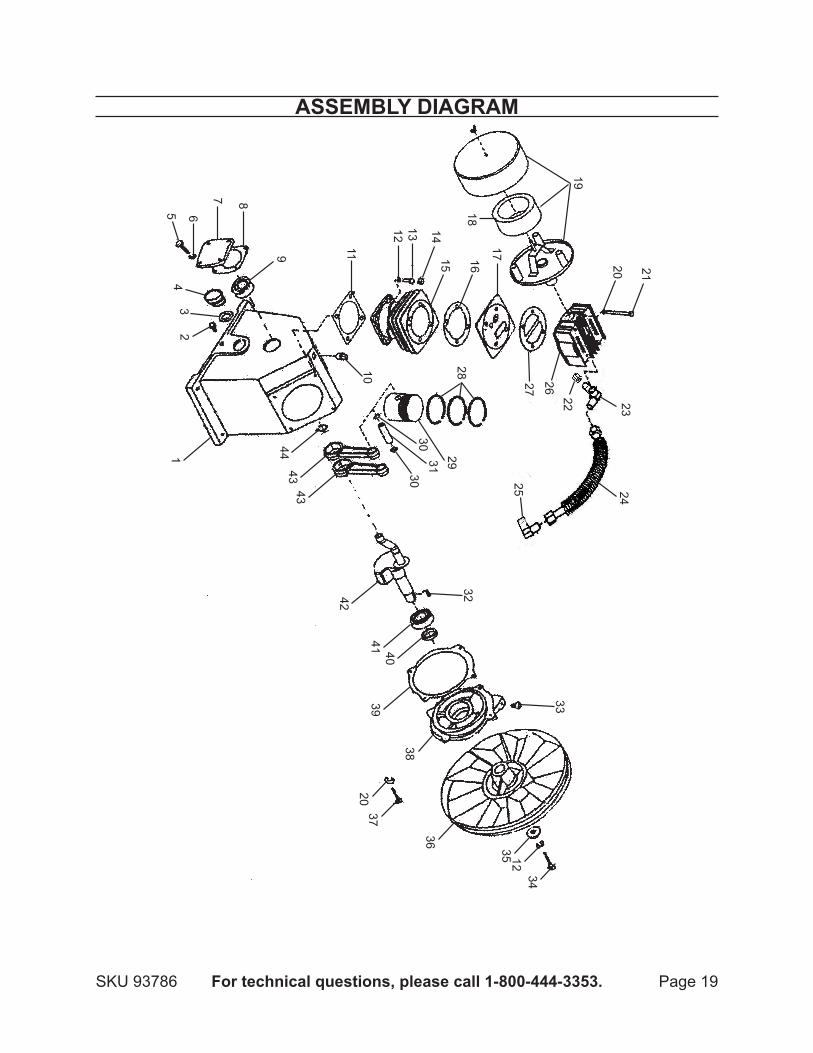
note: Parts 16, 17 and 27 are sold only as an assembly called Cylinder Gasket and Reed Valve Kit.
Page 19for technical questions, please call 1-800-444-3353.SKU 93786
aSSembly dIagram
12
34
5 6
7 8
9
1011
1213 14
15 16
17
18
19
20 21
2829
303130
4443
43
42
32
41 4039
38
2037
36
33
35 1234
27
26
25 24
22 23
Page 20for technical questions, please call 1-800-444-3353.SKU 93786
lImIted 90 day warrantyHarbor Freight Tools Co. makes every effort to assure that its products meet high
quality and durability standards, and warrants to the original purchaser that this product is free from defects in materials and workmanship for the period of 90 days from the date of purchase. This warranty does not apply to damage due directly or indirectly, to misuse, abuse, negligence or accidents, repairs or alterations outside our facilities, criminal activity, improper installation, normal wear and tear, or to lack of maintenance. We shall in no event be liable for death, injuries to persons or property, or for incidental, contingent, special or consequential damages arising from the use of our product. Some states do not allow the exclusion or limitation of incidental or consequential damages, so the above limitation of exclusion may not apply to you. THIS WARRANTY IS EXPRESSLY IN LIEU OF ALL OTHER WARRANTIES, EXPRESS OR IMPLIED, INCLUDING THE WARRANTIES OF MERCHANTABILITY AND FITNESS.
To take advantage of this warranty, the product or part must be returned to us with transportation charges prepaid. Proof of purchase date and an explanation of the complaint must accompany the merchandise. If our inspection verifies the defect, we will either repair or replace the product at our election or we may elect to refund the purchase price if we cannot readily and quickly provide you with a replacement. We will return repaired products at our expense, but if we determine there is no defect, or that the defect resulted from causes not within the scope of our warranty, then you must bear the cost of returning the product.
This warranty gives you specific legal rights and you may also have other rights which vary from state to state.
3491 Mission Oaks Blvd. • PO Box 6009 • Camarillo, CA 93011 • (800) 444-3353