13TH CANADIAN MASONRY SYMPOSIUM H C J TH J...
11
13 TH C ANADIAN M ASONRY S YMPOSIUM H ALIFAX , C ANADA J UNE 4 TH – J UNE 7 TH 2017 SIMPLIFIED DESIGN PROCEDURES FOR UNREINFORCED MASONRY STRUCTURES Mazur, René 1 and Graubner, Carl-Alexander 2 ABSTRACT Unreinforced masonry walls are very well suited to carry vertical loads. In addition, out-of-plane bending moments caused by horizontal loads such as wind or eccentrically applied loads of slabs may occur and have to be taken into account. Since masonry structures according to the European standard Eurocode 6 do not have any computational tensile strength, no bending moments can be carried by a cross section without an existing normal force. That means that the bending capacity depends on the acting normal force. Therefore, a change of the existing vertical loads always results in a change of the horizontal resistance of the structure and vice versa. This paper deals with simplified design procedures in which the influence of the acting bending moment is already integrated in the dimensioning equations of the resistance side. Hence, it is sufficient to compare the acting and the resisting normal force in order to prove the maximum carrying capacity of a wall without considering the bending stress directly. There are also simplified calculation methods dealing with masonry walls under horizontal wind or soil pressure with low vertical load. In this case, a minimum required vertical load has to be determined to resist the acting bending moment. A current research project compares the results of the simplified design methods with a more precise calculation and identifies the boundary conditions for proving that the simplified design methods lead to results on the safe side. Additionally, an investigation of the criteria for using the simplified calculation methods considering an extension on higher walls and longer slab spans was carried out. In this paper the technical background, the results and the restrictions of such simplified design methods will be demonstrated. KEYWORDS: bending moments, mechanical model, simplified design methods, unreinforced masonry, wind loads 1 Research Assistant, Institute of Concrete and Masonry Structures, Technische Universität Darmstadt, Franziska- Braun-Straße 3, 64287 Darmstadt, Germany, [email protected] 2 Professor, Institute of Concrete and Masonry Structures, Technische Universität Darmstadt, Franziska-Braun-Straße 3, 64287 Darmstadt, Germany, [email protected]
Transcript of 13TH CANADIAN MASONRY SYMPOSIUM H C J TH J...

13 T H C A N A D I A N M A S O N R Y S Y M P O S I U M H A L I F A X , C A N A D A JUNE 4TH – JUNE 7TH 2017
SIMPLIFIED DESIGN PROCEDURES FOR UNREINFORCED MASONRY
STRUCTURES
Mazur, René1 and Graubner, Carl-Alexander2
ABSTRACT Unreinforced masonry walls are very well suited to carry vertical loads. In addition, out-of-plane bending moments caused by horizontal loads such as wind or eccentrically applied loads of slabs may occur and have to be taken into account. Since masonry structures according to the European standard Eurocode 6 do not have any computational tensile strength, no bending moments can be carried by a cross section without an existing normal force. That means that the bending capacity depends on the acting normal force. Therefore, a change of the existing vertical loads always results in a change of the horizontal resistance of the structure and vice versa. This paper deals with simplified design procedures in which the influence of the acting bending moment is already integrated in the dimensioning equations of the resistance side. Hence, it is sufficient to compare the acting and the resisting normal force in order to prove the maximum carrying capacity of a wall without considering the bending stress directly. There are also simplified calculation methods dealing with masonry walls under horizontal wind or soil pressure with low vertical load. In this case, a minimum required vertical load has to be determined to resist the acting bending moment. A current research project compares the results of the simplified design methods with a more precise calculation and identifies the boundary conditions for proving that the simplified design methods lead to results on the safe side. Additionally, an investigation of the criteria for using the simplified calculation methods considering an extension on higher walls and longer slab spans was carried out. In this paper the technical background, the results and the restrictions of such simplified design methods will be demonstrated.
KEYWORDS: bending moments, mechanical model, simplified design methods, unreinforced masonry, wind loads
1 Research Assistant, Institute of Concrete and Masonry Structures, Technische Universität Darmstadt, Franziska-
Braun-Straße 3, 64287 Darmstadt, Germany, [email protected] 2 Professor, Institute of Concrete and Masonry Structures, Technische Universität Darmstadt, Franziska-Braun-Straße
3, 64287 Darmstadt, Germany, [email protected]

INTRODUCTION Unreinforced masonry walls are characterized by having only a very low tensile strength. However, these walls are very well suited to carry vertical loads. To carry bending moments, an acting normal force is necessary. To calculate the resistance of an unreinforced masonry structure, it is unavoidable to determine all the acting forces. For the calculation, several load combinations have to be identified to prove that the resistance is always higher than the impact. The most important load combinations are: maximum normal force N and corresponding maximum bending moment M, minimum N and corresponding maximum M, maximum M and corresponding minimum N, maximum M and corresponding maximum N.
Because of the high effort to determine all relevant load combinations to calculate the corresponding internal forces and to design a given masonry structure for each of them, it is desirable to use simplified design rules to determine the resistance without calculating the acting bending moment. Nevertheless, in order to take into account the influence of the acting bending moment indirectly, it is necessary to calculate the load carrying capacity by using the slab span, the height of a wall and the wall thickness.
In the following, the simplified calculation methods and the more precise approach are demonstrated and contrasted. The purpose is to demonstrate the simplicity of the existing calculation methods and to point out the limits of the approaches.
An overview of the discussed standards is given in Table 1.
Table 1: Overview of the discussed standards
General Simplified Europe EC 6-1-1 EC 6-3
German Annex EC 6-1-1/NA EC 6-3/NA
LOAD BEARING CAPACITY AT THE TOP OR BOTTOM OF A WALL
General rules for unreinforced masonry walls The load bearing capacity at the top or bottom of a masonry wall is only determined by compression failure. The design of a masonry cross-section according to Eurocode (EC) 6-1-1 [1] and EC 6-1-1/NA [2] is based on the rigid-plastic material behaviour and depends on the load eccentricity. Equation (1) shows the load bearing capacity according to [1] and [2] in a normalized format.
1 /11 2 2
2slab windm me a
nn
t
t
(EC 6-1-1 & EC 6-1-1/NA) (1)
2 with
d
d
Mm
l t f
Nn
l t f
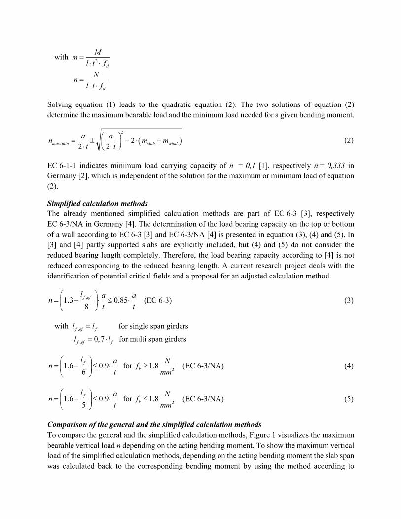
Solving equation (1) leads to the quadratic equation (2). The two solutions of equation (2) determine the maximum bearable load and the minimum load needed for a given bending moment.
2
/ 22 2max min slab wind
a am mn
t t
(2)
EC 6-1-1 indicates minimum load carrying capacity of n = 0,1 [1], respectively n = 0,333 in Germany [2], which is independent of the solution for the maximum or minimum load of equation (2).
Simplified calculation methods The already mentioned simplified calculation methods are part of EC 6-3 [3], respectively EC 6-3/NA in Germany [4]. The determination of the load bearing capacity on the top or bottom of a wall according to EC 6-3 [3] and EC 6-3/NA [4] is presented in equation (3), (4) and (5). In [3] and [4] partly supported slabs are explicitly included, but (4) and (5) do not consider the reduced bearing length completely. Therefore, the load bearing capacity according to [4] is not reduced corresponding to the reduced bearing length. A current research project deals with the identification of potential critical fields and a proposal for an adjusted calculation method.
,1.3 0.8
85f ef an
t
l a
t
(EC 6-3) (3)
,
,
for single span girders with
for multi span girders0,7
f ef f
f ef f
l l
l l
21.6 0 for9 . 1.8
6f
k
an f
l N
mmt
(EC 6-3/NA) (4)
21.6 0 for9 8
5. 1.f
k
an f
l N
mmt
(EC 6-3/NA) (5)
Comparison of the general and the simplified calculation methods To compare the general and the simplified calculation methods, Figure 1 visualizes the maximum bearable vertical load n depending on the acting bending moment. To show the maximum vertical load of the simplified calculation methods, depending on the acting bending moment the slab span was calculated back to the corresponding bending moment by using the method according to

EC 6-1-1/NA Annex C [2]. Because of the higher precision of the general method, this method should always lead to a higher resistance than the simplified method to get results on the safe side.
Figure 1: Load bearing capacity at the top or bottom of a masonry wall according to EC 6-1-1 and EC 6-3 as a function of the acting bending moment
Another possibility to compare the different methods is to calculate the normalized load capacity n depending on the slenderness λ = h/t. To get a realistic comparison three different load combinations were executed. The used safety factors γ and combination coefficients ψ are listed in Table 2.
Table 2: List of safety factors and combination coefficients for the executed load cases
Load type Load combination max N + corr. max M max M + corr. max N min N + corr. max M
Dead load (g + Δg)k γ = 1.35 / - γ = 1.35 / - γ = 1.00 / - Live load qk γ = 1.50 / ψ = 1.0 γ = 1.50 / ψ = 0.7 γ = 0.00 / -
Wind load wk γ = 1.50 / ψ = 0.6 γ = 1.50 / ψ = 1.0 γ = 1.50 / ψ = 1.0
The explained comparison (n on λ) is shown in Figure 2 for a specific system. The chosen live load is conform to the criteria for using the simplified calculation methods. It can be seen that according to the actual simplified calculation methods the resistance of the wall is almost always less than or equal to the results determined by the general design rules. The partly identified problem of “too large resistances” according to the simplified calculation methods – which also exists for fully supported slabs (see Figure 3) – occurs primary out of the relevant range for the construction
0
0.1
0.2
0.3
0.4
0.5
0.6
0.7
0.8
0.9
1
0 0.02 0.04 0.06 0.08
n =
N/(
l∙t∙f
d)
m = M/(l∙t²∙fd)
General: n = 1 - 2 m/n
Simplified: n = 1.6 - lf/6 ≤ 0.9 ∙ a/t
Simplified: n = (1.3 - lf/8) ∙ a/t ≤ 0.85 ∙ a/t
a/t = 2/3fk = 2.5 N/mm²EWall = 1100 ∙ fkt = 0,49 m h = 2.75 mLive load:
qk = 5.0 kN/m²Add. dead load:
Δgk = 1.7 kN/m²Floor thickness
according to Eurocode 2 chapter 7.4.2
Concrete C25/30
lf = 4.25 m
lf = 6.5 m
.

practice. Usually the slenderness of a wall is greater than λ = 5.5. Concerning the resistance of a masonry wall, buckling failure or failure due to second order effects at the mid height are the governing failure modes. Therefore, regarding the relevant range and within the criteria for using the simplified calculation methods, there is no lack of safety.
Figure 2: Load bearing capacity at the top or bottom of a masonry wall according to EC 6-1-1 and EC 6-3 as a function of the slenderness λ for a/t = 2/3
Figure 3: Load bearing capacity at the top or bottom of a masonry wall according to EC 6-1-1 and EC 6-3 as a function of the slenderness λ for a/t = 1

The progress of the diagram curves for the general calculation methods are reasoned in the calculation of the bending moments at the top and the bottom of a masonry wall according to EC 6-1-1/NA Annex C [2], respectively the European version [1]. This method is based on a linear elastic internal force calculation. Therefore, the bending moments highly depend on the stiffness of the walls and the slab at the considered wall-ceiling-node. That means that a high wall with a low stiffness has a lower bending moment than a wall with less height. For an increasing height of a wall, wind loads are governing, so the bending moments are increasing and the load bearing capacity of the wall declines. If there are no wind loads and the height of the wall will increase, the bending moment would approach m = 0 and the load bearing capacity will reach the maximum value of n = 0.6 (see Figure 2) or rather n = 0.9 (see Figure 3). Respectively, the minimum vertical load needed would converge at n = 0.
LOAD BEARING CAPACITY AT THE MID HEIGHT OF A WALL
General rules for unreinforced masonry walls At the mid height of a masonry wall buckling failure or compression failure due to second order effect usually are governing. The design equation of EC 6-1-1 [1] goes back to Kirtschig (1976) [5] and is based on experimental results (see equation (7)). The German equivalent according to [2] (see equation (8)) goes back to Mann (1992) [6] and is a linear approximation of the European equation (7) [7]. The basis of equation (8) is a young’s modulus of E = 700 ∙ fk [8]. Equation (8) is solved to the normalized resistance n and results in equation (9) which also integrates the initial eccentricity einit = λ/450. It is not possible to solve the European equation (7) to n to get a closed solution.
2
21
u
mn A e
(EC 6-1-1) (7)
1 with
0.063
0.73 1.17
1 2 mk
mk
ef k
eA
t
ue
th f
t E
1 2 0.024 1 21.14 efmk mkmn
t
he e
t t
(EC 6-1-1/NA) (8)
2
,max/min
109 1092.28
75000.57
750 57
0.
0m slab wind
a am m
t tn
(9)

The European and the German equations for the resistance at the mid height of a masonry wall also lead to a maximum bearable normal force and a minimum vertical load needed on a wall like equation (1) or rather equation (2) for the top or bottom of a wall
Simplified calculation methods – load bearing capacity The simplified verification equations according to [3] and [4] are given in (10) and (11).
2
0.85 0.0011 efm
ha
ttn
(EC 6-3) (10)
2
0.00110.85 efm
han
t t
(EC 6-3/NA) (11)
Simplified calculation methods – minimum vertical load needed In contrast to the top or bottom of the wall there are simplified verification methods to determine a minimum vertical load needed at the mid height of a masonry wall (see equation (12) [3] and (13) [4]). For achieving a closed solution for the minimum vertical load needed according to [3], some assumptions are necessary (see [9]). In both equations, the acting wind load wEd and the slenderness λ are the governing factors. It should be mentioned that the European rule (see equation (12)) is applicable with partly supported slabs.
2 2
,
25 1 1 1 1 25
2 6
25
827 67Ed
Ed mind
w
fn
(EC 6-3) (12)
2
,
3
16300
EdEd min
d
an
w
ft
(EC 6-3/NA) (13)
A more realistic solution to determine the necessary minimum vertical load was presented by Graubner & Schmitt (2016) [10].
Comparison of the general and the simplified calculation methods For the comparison of the four verification methods for the middle height of a wall according to the European and the German rules, only the governing load combination is shown in Figure 4.
In the relevant range for the construction practice and within the criteria for using the simplified calculation methods, the results for the resistance according to the simplified calculation methods are lower than the corresponding results according to the general rules. Therefore, the results are conservative.

Regarding the necessary minimum vertical load level both simplified calculation methods lead to more favourable results than the general rules. The authors assume that there is no lack of safety in this case, as the necessary minimum load needed according to the simplified calculation methods is based on a verified mechanical model.
Figure 4: Load bearing capacity at the mid height of a masonry wall according to EC 6-1-1 and EC 6-3 as a function of the slenderness λ for a/t = 2/3
An overall comparison of the simplified and the general calculation methods according to the European and the German rules including the design equations for the top and bottom of a wall and the design equations at the mid height of a wall would lead to almost the same results as shown in Figure 4.
EXTENSION OF THE CRITERIA FOR USING THE SIMPLIFIED CALCULATION METHOD To ensure that the load bearing capacity calculated with the simplified calculation method does not exceed the load capacity of the general calculation method, criteria for using the simplified method are essential. Two current conditions are a restricted wall height with the maximum of h = 2.75 m and h = 12 ∙ t and a slab span up to lf = 6.0 m according to [11]. Other researches already demonstrated the possibility of extending the criteria for using the simplified calculation methods for clay masonry and calcium silicate masonry under special boundary conditions (see [12] and [13]). An objective in a recent research is the extension of the criteria for using Eurocode 6-3/NA [4]. To evaluate the possibility of further extension different unfavourable boundary

conditions were tested in comparative calculations. A first proposal for clay and calcium silicate masonry and autoclaved aerated concrete units is shown in Figure 5. One major advantage is the extension of the maximum slab span up to lf = 7.0 m. However, in this case the live load is limited to qk = 3.0 kN/m². If the boundary conditions were adjusted separately for every type of brick or block unit, there would still be potential for a further extension.
Figure 5: First proposal for an extension of the criteria for using in case of calcium silicate, clay and autoclaved aerated concrete units [15]
2
2.5
3
3.5
4
4.5
5
5.5
6
6.5
7
15 20 25 30 35 40 45
wal
l hei
ght h
[m
]
wall thickness t [cm]
fk ≥ 7,0 N/mm²
fk ≥ 4,0 N/mm²
EC 6-3/NA
15,0 17,5 20,0 24,0 30,0 36,5 42,5 49,0
lf ≤ 7.0 mh ≥ 2.50 mEfloor = 31,000 N/mm²∆gk ≤ 1.7 kN/m²qk ≤ 3.0 kN/m²wEd ≤ 1.3 kN/m²
Fully supported slabcalcium silicate unitswith a/t = 1.0final creep coefficient φ = 1.5Limiting value of slenderness:λc = 12Young's modulus: E = 950 · fk
Partly supported slabwith a/t = 2/3clay masonry unitsφ = 1.0; λc = 15; E = 1100 · fkautoclaved aerated conreteunitsφ = 0.5; λc = 20; E = 550 · fk
fk ≥ 3,0 N/mm²
fk ≥ 4,5 N/mm²
fk ≥ 1,8 N/mm²
fk ≥ 1,0 N/mm²

DESIGN TABLES Design tables for determining the vertical resistance of a wall were developed at the Institute of Concrete and Masonry Structures in Darmstadt, in order to use the simplified calculation methods even more efficiently [14]. This was possible because in the simplified calculation methods the load capacity is independent from the acting forces. Table 3 shows the resistance factors of an exemplary wall with a height of h = 3.00 m. The vertical resistance of a masonry wall can be calculated easily by multiplying the factor T according to Table 3 with the characteristic compressive strength.
Table 3: Vertical resistance of a masonry wall for fk ≥ 1.8 N/mm² (h = 3.00 m) [14]
Design value of the vertical resistance of a masonry wall nRd (für fk ≥ 1,8 N/mm²) nRd in kN/m = T · fk in N/mm²
Hei
ght
of t
he
wal
l h
in m
Th
ick
nes
s of
th
e w
all
t in
cm
Inte
rmed
iate
b
eari
ng
End bearing
Bearing length Roof storey
Fully supported slab a/t = 1.0
a/t = 2/3
a/t = 1/2
a/t = 1,0
a/t = 2/3
a/t = 1/2
Slab span lf in m
≤ 6.0 ≤ 4.5 5.0 5.5 6.0 ≤ 6.0 ≤ 6.0 ≤ 6.0 ≤ 6.0 ≤ 6.0
3.00
24.0 96 - - - - - - 45 - -
30.0 125 125 116 102 77 53 56 56 53
36.5 160 160 158 141 124 101 72 68 68 68
42.5 191 191 184 164 144 123 89 80 80 80
49.0 224 224 212 189 166 145 106 92 92 92
SUMMARY This paper deals with simplified calculation methods for the determination of the maximum vertical load on masonry walls and the necessary minimum vertical load under horizontal wind pressure. It is possible to determine the load bearing capacity for predominant vertically loaded walls without any information about the acting internal forces, which are usually difficult to identify. The basic parameters are the slenderness of the wall, the adjacent slab span and the bearing length. To calculate the minimum vertical load for masonry walls under wind pressure, only the geometric parameters and the acting horizontal loads are required. In addition to a simplified approach for the load bearing capacity, a more efficient design is possible by using tables and diagrams to determine the required minimum vertical load as well as the maximum load bearing capacity. Because of these advantages, it is desirable to extend the criteria for using the presented methods by conducting a comprehensive parameter study or adjusting the existing mechanical models.

REFERENCES [1] DIN EN 1996-1-1 (2013-02). Eurocode 6: Design of masonry structures – Part 1-1: General
– Rules for reinforced and unreinforced masonry structures; DIN Deutsches Institut für Normung e. V., Berlin, Germany
[2] DIN EN 1996-1-1/NA (2012-05) including revision A1 (2014-03) and A2 (2015-01). National Annex – Eurocode 6: Design of masonry structures – Part 1-1: General – Rules for reinforced and unreinforced masonry structures; DIN Deutsches Institut für Normung e. V., Berlin, Germany
[3] DIN EN 1996-3 (2010-12). Eurocode 6: Design of masonry structures – Part 3: Simplified calculation methods for unreinforced masonry structures; DIN Deutsches Insitut für Normung e. V., Berlin, Germany
[4] DIN EN 1996-3/NA (2010-01) including revision A1 (2014-03) and A2 (2015-01). Eurocode 6: Design of masonry structures – Part 3: Simplified calculation methods for unreinforced masonry structures; DIN Deutsches Insitut für Normung e. V., Berlin, Germany
[5] Kirtschig, K. (1976). “Tragfähigkeit von Mauerwerk bei vertikaler Belastung - Traglastverfahren” Mauerwerk-Kalender 1976, 287 – 321, Ernst & Sohn, Berlin, Germany
[6] Mann, W. (1992). “Grundlagen der Bemessung gemauerter Wände unter vertikaler Belastung nach Eurocode EC 6 unter Berücksichtigung der Knickgefahr und Vergleich mit Versuchsergebnissen” Mauerwerk-Kalender 1992, 593 – 599, Ernst & Sohn, Berlin, Germany
[7] Jaeger, W. and Marzahn G. (2010). Mauerwerk: Bemessung nach DIN 1053-100, Ernst & Sohn, Berlin, Germany
[8] Alfes, C., Brameshuber, W., Graubner, C.-A., Jaeger, W., Seim, W. (2013). Der Eurocode 6 für Deutschland – DIN EN 1996: Bemessung und Konstruktion von Mauerwerksbauten mit Nationalen Anhängen – Kommentierte Fassung, Ernst und Sohn, Berlin, Germany
[9] Schmitt, M., Graubner, C.-A., Förster, V. (2015). „Minimum vertical load on masonry walls – a realistic view“. Mauerwerk 19 (2015), Vol. 6, 245 – 257, Ernst & Sohn, Berlin, Germany
[10] Graubner, C.-A. & Schmitt, M. (2016). “Loadbearing capacity of masonry walls under predominant bending due to wind loads” 16th International Brick and Block Masonry Conference (2016), Padova, Italy
[11] Mann, W. & Schulenberg, W. (1983). Sicherheitstheoretische Untersuchungen auf dem Gebiet des Mauerwerksbaus, Lehrstuhl für Statik der Hochbaukonstruktionen, Darmstadt, Germany
[12] Graubner, C.-A., Schmitt, M., Förster, V. (2014). “Erweiterte Anwendungsgrenzen von DIN EN 1996-3/NA für Ziegelmauerwerk bei weit gespannten, teilaufliegenden Decken” Mauerwerk 18 (2014), Vol. 6, 357 – 364, Ernst & Sohn, Berlin, Germany
[13] Graubner, C.-A. & Förster, V. (2014). Research paper F15-13-2014, Institute of Concrete and Masonry Structures, Technische Universität Darmstadt, Germany
[14] Graubner, C.-A., Schmitt, M., Förster, V. (2014). “Design Tables for URM – Hilfsmittel für die praxisnahe Bemessung von unbewehrtem Mauerwerk”. Mauerwerk 18 (2014), Vol. 6, 178 – 187, Ernst & Sohn, Berlin, Germany
[15] Graubner, C.-A., Faust, T., Purkert, B., Mazur, R., Krieger, L., Müller, D., Förster, V. (2017). “Erweiterung des Anwendungsgebiets der vereinfachten Berechnungsmethoden nach EN 1996-3/NA” Internal research paper (unpublished), PRB-PG5 Mauerwerksbau, Berlin, Germany