MFMcGrawCh08-Rotation - Revised 3/7/20101 Chapter 8 ROTATION.

RDLO / RDLO VType Series Booklet1387.5/2--10
Axially Split Volute Casing Pumps
Fields of ApplicationWaterworks, irrigation and drainage pumping stations, powerstations, industrial water supply systems, shipbuilding as wellas general petrochemical applications.
Operating DataPump sizes DN 350 to 700Capacities Q to 2800 l/sHeads H to 240 mOperating pressures p to 25 barOperating temperatures T to +105 _C
Design
Single--stage, axially split volute casing pump with double--en-try radial impeller, for horizontal and vertical installation.Horizontal drive installed either to the left or right of the pump.Connecting flanges drilled on option to ISO, DIN or ASME.
Shaft SealGland packing or single--acting, hydraulically balanced, rever-sible mechanical seal.
Designation
BearingsRDLO: Grease--lubricated rolling element bearings at
either end, optional: oil lubrication
RDLO V: Grease--lubricated rolling element bearings, bot-tom bearing on option as product--lubricatedplain bearing
Materialsto either DIN or ASTM standards
Volute casing Cast ironNodular cast ironNi--Resist
Impeller BronzeCrNi cast steel
Shaft Min. 13% chrome steelDuplex steel
Shaft protecting sleeve Min. 13% chrome steelDuplex steel
Casing wear ring BronzeDuplex cast steel
RDLO V 500 -- 685 A
Type series
Discharge nozzle DNNominal impeller diameter [mm]Impeller form
Vertical installation
01 P FLubrication of bearings(F= grease, O= oil,M = pumped medium)
Shaft seal (P= gland packing,G= mechanical seal)
Material combination acc. to table
RDLO / RDLO V
2 1387.5/2--10Subject to technical modifications
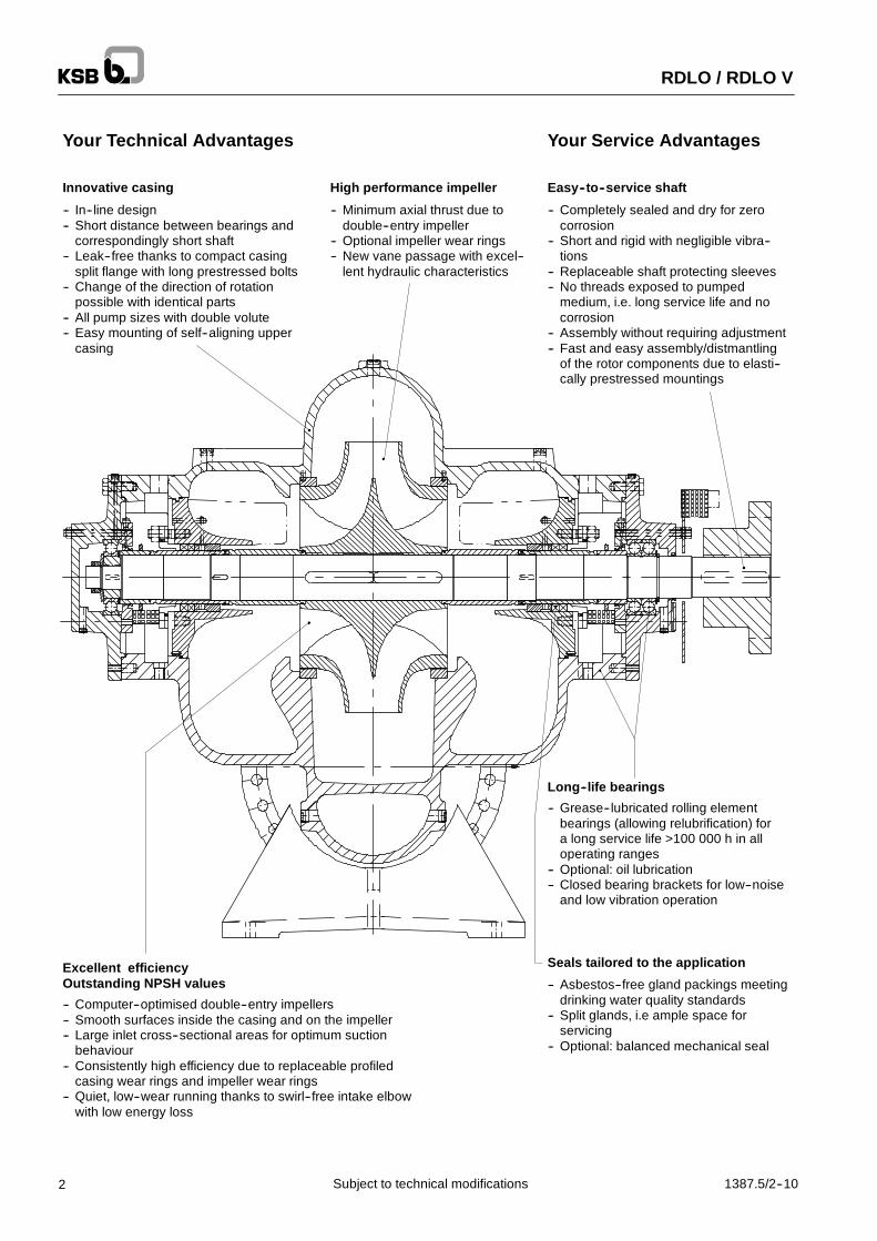
Your Technical Advantages
Innovative casing
-- In--line design-- Short distance between bearings and
correspondingly short shaft-- Leak--free thanks to compact casing
split flange with long prestressed bolts-- Change of the direction of rotation
possible with identical parts-- All pump sizes with double volute-- Easy mounting of self--aligning upper
casing
-- Minimum axial thrust due todouble--entry impeller
-- Optional impeller wear rings-- New vane passage with excel--
lent hydraulic characteristics
-- Completely sealed and dry for zerocorrosion
-- Short and rigid with negligible vibra--tions
-- Replaceable shaft protecting sleeves-- No threads exposed to pumped
medium, i.e. long service life and nocorrosion
-- Assembly without requiring adjustment-- Fast and easy assembly/distmantling
of the rotor components due to elasti--cally prestressed mountings
-- Computer--optimised double--entry impellers-- Smooth surfaces inside the casing and on the impeller-- Large inlet cross--sectional areas for optimum suction
behaviour-- Consistently high efficiency due to replaceable profiled
casing wear rings and impeller wear rings-- Quiet, low--wear running thanks to swirl--free intake elbow
with low energy loss
-- Grease--lubricated rolling elementbearings (allowing relubrification) fora long service life >100 000 h in alloperating ranges
-- Optional: oil lubrication-- Closed bearing brackets for low--noise
and low vibration operation
-- Asbestos--free gland packings meetingdrinking water quality standards
-- Split glands, i.e ample space forservicing
-- Optional: balanced mechanical seal
Excellent efficiencyOutstanding NPSH values
Long--life bearings
Seals tailored to the application
Your Service Advantages
Easy--to--service shaftHigh performance impeller

RDLO / RDLO V
31387.5/2--10 Subject to technical modifications
Contents
Selection Charts 50 Hz / 60 Hz Page 4General Information: -- Scope of Supply
-- Packaging and Dispatch / Transport-- Guarantee, Inspections/Testing and Quality Assurance-- Order Data
Page 5
Types of Installation Page 6Directions of Rotation / Flow Page 7Materials / Application Limits Page 7Pressure Limits Page 8Technical Data Page 9Speed Control; Vibration Behaviour Page 10Surface Coating Page 10Arrangement of Sealing and Flushing Pipe Page 11Sectional Drawing RDLO Page 12Options: oil lubrication, resistance thermometer PT 100 Page 13Sectional Drawing RDLO V Page 14Detail of bottom bearing Page 15Option: Product--lubricated Plain Bearing Page 15Option: Gland Packing Page 16Option: Mechanical seal (balanced) Page 16Option: Impeller with impeller wear ring Page 16Noise Characteristics for Pumps without Motor Page 17Dimension Tables RDLO Page 18 -- 23Dimension Tables RDLO V Page 24 -- 29General Arrangement Drawing 2E Page 30 -- 35General Arrangement Drawing 3E Page 36 -- 41General Arrangement Drawing 4E Page 42 -- 47General Arrangement Drawing DK Page 48 -- 53Recommended Spare Parts for Commissioning Page 54Recommended Spare Parts for 2 Years‘ Operation Page 55Recommended Spare Parts for 5 Years‘ Operation Page 56Interchangeability of Pump Components, Horizontal Pump Page 57Interchangeability of Pump Components, Vertical Pump with Rolling Element Bearingat Bottom
Page 58
Interchangeability of Pump Components, Vertical Pump with Plain Bearing at Bottom Page 59

RDLO / RDLO V
4 1387.5/2--10Subject to technical modifications
Selection Chart 50 Hz5000 6000 7000 8000 10000 12000 14000 16000 20000 25000 30000 45000Q [U.S. gpm]
200
150
100
80
60
40
30
20
500
300
200
100
50
H[ft]
300 400 500 600 700 800 1000 2000 3000
1200 1500 2000 3000 5000 7500 10000
Q [l/s]
Q [m3/h]
H[m]
350--690
1480 1/min
350--575
1480 1/min
400--705
985 1/min
400--665
985 1/min
400--525
985 1/min
500--585
985 1/min
500--1015
985 1/min500--1035
985 1/min
600--1075
985 1/min
400--935
985 1/min
500--835
985 1/min
700--980
985 1/min600--885
985 1/min500--860
985 1/min
700--980
740 1/min
600--705
985 1/min
600--600
985 1/min
500--685
985 1/min
Selection Chart 60 Hz5000 6000 7000 8000 10000 12000 14000 16000 20000 25000 30000 45000Q [U.S. gpm]
200
150
100
80
60
40
30
20
H[m]
250
300 400 500 600 700 800 1000 2000 3000Q [l/s]
1200 1500 2000 3000 5000 7500 10000Q [m3/h]
500
300
200
100
50
H[ft]
350--690
1780 1/min 400--935
1180 1/min
350--575
1780 1/min
350--690
1180 1/min
350--575
1180 1/min
400--525
1180 1/min
400--705
1180 1/min
400--665
1180 1/min
500--835
1180 1/min
500--860
1180 1/min600--1075
895 1/min
700--980
895 1/min
600--600
1180 1/min
500--585
1180 1/min
600--885
895 1/min
700--980
715 1/min
500--685
1180 1/min
600--705
1180 1/min
� �opt A--type impeller
� �opt B--type impeller

RDLO / RDLO V
51387.5/2--10 Subject to technical modifications
Scope of Supply
RDLO:Pump with bare shaft end, priming coat, gland packing, 4 instruction manuals
RDLO V:Pump with bare shaft end, baseplate, priming coat, gland packing, 4 instruction manuals
Available against extra charge:-- oil--lubricated rolling element bearings, mechanical seal, interior coating meeting drinking water quality standards,
finish coat, baseplate for pump or pump/motor, motor stools for vertical installation, materials testing, additionalinstruction manuals
Available accessories:-- coupling and coupling guard, vibration sensor SPM nipple-- set of pressure gauges, cyclone separator with piping-- vent valve, drain valve-- temperature sensor for rolling element bearing (PT 100), limit--value alarm for PT 100-- universal--joint shaft for two--floor installation
Packaging and Dispatch / Transport
RDLO:Where appropriate, the pump sets are assembled completely at the factory in order to check them for proper adjust-ment. Afterwards they are disassembled for shipping, and the components are dispatched separately.
RDLO V:The vertical pump, the motor stool, and the associated motor are dispatched separately.
Guarantee, Inspections/Testing, Quality Assurance
Each pump is subjected to a functional test. The operating data are guaranteed by way of a performance test in accor-dance with ISO 2548 C, DIN 1944/III or comparable international codes/standards.
A performance test witnessed by the customer in accordance with ISO / DIN or comparable codes/standards can beperformed against extra charge.
The quality of our RDLO products is ensured by a quality assurance system audited and certified to DIN ISO 9001/ EN 29001.
Order Data
Pump:-- Designation of the pump according to “Designation”-- Capacity Q-- Discharge head H (Hgeo and system losses)-- Material combinations-- lange design (bolt hole pattern)-- Shaft seal: gland packing or mechanical seal-- Grease or oil lubrication of bearings-- Medium pumped and temperature of medium pumped-- Solids content-- Direction of rotation / motor position-- Accessories required-- Quantity and language of instruction manuals
Motor:(selected by KSB)-- Type of construction-- Type of enclosure-- Voltage, frequency, starting method-- Ambient temperature-- Thermal class-- Accessories required
(provided by customer)Binding dimensional drawing and data sheets of motor incl. specification of the effective speed to be submitted withthe purchase order.

RDLO / RDLO V
6 1387.5/2--10Subject to technical modifications
Types of installation
Horizontal
3E
2E
4E
Vertical
DK DJ

RDLO / RDLO V
71387.5/2--10 Subject to technical modifications
Directions of Rotation / FlowHorizontal Vertical
Direction of rotation asviewed from the shaft end“anticlockwise”
Direction of rotation asviewed from the shaft end“clockwise”
Direction of rotation asviewed from the shaft end“anticlockwise”
Direction of rotation asviewed from the shaft end“clockwise”
Materials / Application Limits
Temperatures Gland packing / mechanical seal: max. 105 �C 25 _C
Media pumpedCrude water / non--potable waterSolids content max. 100 mg/l 1)
Sea watermax. 100 mg/l
Part No DescriptionMaterial combination
Part No. Description01 011 02 021 03 031 04 041 052) 062)
102 Volute casing 3) Castiron
Nodularcastiron
Castiron
Nodularcastiron
Castiron
Nodularcastiron
Castiron
Nodularcastiron
Ni--Resist
211 Shaft Min. 13 % chrome steel Duplex steel234 Impeller Bronze Austenitic cast steel350 Bearing housing Cast iron360 Bearing cover Steel441 Shaft seal housing Cast iron Ni--Resist452 Gland Nodular cast iron502 Casing wear ring Bronze Duplex cast steel
503 Impeller wear ring -- Bronze -- Duplex caststeel --
Duplexcaststeel
524 Shaft protecting Gland packing: min. 13 % chrome steel524 Shaft protecting
sleeve Mechanical seal: bronze Duplex steel433 Mechanical seal Carbon / SiC (B Q1EGG to DIN 24960)901.1 Hexagon head bolt Quenched and tempered steel Duplex steel
1) Other pumped media and solids contents on request2) On request3) Select the material for the volute casing based on the operating pressure and test pressure (see page 8)

RDLO / RDLO V
8 1387.5/2--10Subject to technical modifications
Pressure Limits
Operating Pressure and Test Pressure:
The standard test pressure is calculated as follows:1.2 x (HQ=0 + HInlet) or 1.5 x (HQ=Qopt + HInlet) The higher value is to be usedThe values for operating pressure and test pressure of the RDLO stated in the table below must not be exceeded.
Permissible operating pressures in bar Maximum permissible test pressures in bar
Pump sizes Material combinationsPump sizes
01/02 03/04 11/21 31/41 05/06*) 01/02 03/04 11/21 31/41 05/06*)
350--575 8.5 8.5 19.4 19.4 *) 10.2 10.2 23.6 23.6 *)
350--690 10.2 10.2 25.0 25.0 *) 12.2 12.2 31.5 31.5 *)
400--705 9.9 9.9 14.4 14.4 *) 11.8 11.8 18.0 18.0 *)
400--935 9.5 9.5 25.0 25.0 *) 11.4 11.4 32.1 32.1 *)
400--525 7.6 7,6 10.9 10.9 *) 9.1 9.1 13.1 13.1 *)400--665 8.9 8.9 17.9 17.9 *) 10.7 10.7 21.6 21.6 *)
500--585 8.1 8.1 9.7 9.7 *) 9.7 9.7 11.6 11.6 *)
500--685 8.1 8.1 13.0 13.0 *) 9.7 9.7 15.6 15.6 *)
600--600 7.3 7.3 9.3 9.3 *) 8.7 8.7 11.2 11.2 *)
600--705 7.2 7.2 12.7 12.7 *) 8.6 8.6 15.2 15.2 *)500--835 8.1 8.1 19.6 19.6 *) 9.7 9.7 24.0 24.0 *)
500--1015 8.5 8.5 21.5 21.5 *) 10.2 10.2 27.0 27.0 *)
500--860 7.5 7.5 19.2 19.2 *) 8.9 8.9 23.6 23.6 *)
500--1035 8.5 8.5 21.7 21.7 *) 10.2 10.2 27.0 27.0 *)
600--885 7.6 7.6 14.8 14.8 *) 9.1 9.1 18.0 18.0 *)600--1075 8.4 8.4 23.0 23.0 *) 10.1 10.1 28.5 28.5 *)
700--980 7.7 7.7 17.2 17.2 *) 9.3 9.3 20.7 20.7 *)
*) On request
FlangesWhen specifying the casing flanges, the following must be observed:-- Nominal pressures of flanges � operating pressures-- Flanges of suction and discharge nozzles have equal nominal pressures-- The permissible codes/standards for the flanges and the nominal pressures are stated in the dimension tables.

RDLO / RDLO V
91387.5/2--10 Subject to technical modifications
Technical Data all dimensions in mm
Seal chamber dimensions
Pump sizes Shaft diameter Inside diameter d Outside diameter Length LPump sizes Shaft diameterat bearing fit Gland
packing Mechanical seal
Outside diameterD
Length L
350--575350--690
100 130 125 170400--705
100 130 125 170
400--935400--525
120400--665
120
500--585110 140 135 180
500--685110 140 135 180
600--600600--705500--835500--860
130 160 155 210500--1015
130 160 155 210
500--1035 140600--885
140
600--1075 150 180 175 230700--980
150 180 175 230
Pump sizes
Permissibleforces acting
on the nozzles
Permissiblemoments actingon the nozzles
Mass moments of inertia J(without coupling)
Pump sizesFx, Fy, Fz1) 2)
Mx, My, Mz1) 2)
in kgm2
N N Nm Nm without water with water350--575
5900 8300 3300 46004.325 6.0
350--6905900 8300 3300 4600
5.44 6.975400--525 3.45 4.875400--665
6900 9700 3800 53007.5 10.35
400--7056900 9700 3800 5300
8.65 11.85400--935 20.18 27.64500--585 5.15 7.275500--685 10.08 13.95500--835
8800 12300 4900 690017.8 25.5
500--8608800 12300 4900 6900
28.2 36.24500--1015 32.45 46.5500--1035 48.3 62.08600--600 8.5 13.6600--705
10700 15000 6000 840013.7 18.5
600--88510700 15000 6000 8400
29.23 38.77600--1075 51.65 68.52700--980 12600 17600 7100 9900 61.75 66.45
1) Values applicable for casing material cast iron2) Values applicable for casing material nodular cast iron and Ni--Resist
FzMz
Fy
My
Fx
Mx

RDLO / RDLO V
10 1387.5/2--10Subject to technical modifications
Speed ControlIf speed control is provided, we recommend to always select mechanical seals for the shaft!The speeds stated in the selection charts on page 4 must not be exceeded!
Vibration BehaviourVibration values of the pump to ISO 10816--3, machinery class 3, zone B:In the operating range of 0.5 to 1.2 x QOpt: Veff≤ 4.5 mm/s
Surface CoatingApplication range ≤ 60 �C > 60 �C
Casing materialGrey cast iron /
Nodular cast iron DuplexGrey cast iron /
Nodular cast iron Duplex
Normal Type A No coating No coating No coating
Casing, insideDrinking water
With coating approvedfor drinking water
applicationsNo coating -- --
Casing, outside Normal Type A Type A Type B Type B
Special surface coating for higher temperatures available on request
Type A) Standard surface coatingCoating Interior 1) Exterior (ZN 35 EN B1--3) 2)
Preparatory treatment Grease--free / blasting SA1 Grease--free / blasting SA1A Primer 1--component anti--rust primer 1--component anti--rust primer
Without extracharge
Intermediate coat -- without -- -- without --charge
Finish coat -- without --1--component acrylate--alkyd compound, ap-
prox. 0.04 mm, water--thinned, RAL 5002 ultra-marine blue
1) not approved for drinking water applications2) maximum permissible temperature 80 �C. Not suited for outdoor installation
Type B) Special surface coatingCoating Interior 1) Exterior (ZN 35 ES1N A1--4) 3)
Preparatory treatment Grease--free / blasting SA1 Grease--free / blasting SA1
BAgainst extra
Primer 1--component anti--rust primer2--component epoxy zinc dust, approx. 0.04
mmAgainst extracharge, as per
price list Intermediate coat -- without --2--component epoxy resin (EG1), approx. 0.06
mm
Finish coat -- without --2--component polyurethane coating, approx.
0.04 mm, RAL 5002 ultramarine blue1) not approved for drinking water applications3) maximum permissible temperature 150 �C. Weatherproof; suited for industrial and marine atmospheres
Type C) Surface coating at customer’s optionCoating Interior 1) Exterior
Preparatory treatment Grease--free / blasting SA1 Blasting SA 2 1/2 , DIN EN ISO 12944--4
C Primer 1--component anti--rust primer2--component epoxy zinc dust, approx. 0.04
mmupon request
Intermediate coat -- without --Coating according to customer specification or
by customer
Finish coat -- without --Coating according to customer specification or
by customer
1) not approved for drinking water applications
Option interior coating approved for drinking water applicationsCoating Interior (ZN 35 EST A1--3) 4) Exterior
Preparatory treatment Blasting SA 2 1/2 , DIN EN ISO 12944--4 Blasting SA 2 1/2 , DIN EN ISO 12944--4
Against extracharge as per
Primer2--component epoxy resin compound, approx.
0.125 mm, RAL 7032 pebble grey, (Icosit TW3)2--component epoxy zinc dust, approx. 0.04
mmcharge, as per
price list Intermediate coat -- without --Coating according to customer specification or
by customer
Finish coat2--component epoxy resin compound, approx.
0.125 mm, RAL 7032 pebble grey, (Icosit TW3)Coating according to customer specification or
by customer
4) approved for drinking water applications, maximum permissible temperature 60�C.
Coatings at customer’s option (interior and/or exterior coatings) may only be offered after consultation andtechnical clarification

RDLO / RDLO V
111387.5/2--10 Subject to technical modifications
Arrangement of Sealing and Flushing Pipe
RDLO, clean water operation RDLO, waste water operation
RDLO V, clean water operation RDLO V, waste water operation
(Vent and drain valves available as accessories)

RDLO
12 1387.5/2--10Subject to technical modifications
Sectional Drawing (horizontal design)
Part No. Description Part No. Description Part No. Description102 Volute casing 412 O--ring 524 Shaft protecting sleeve145 Adapter 441 Shaft seal housing 525 Spacer sleeve211 Pump shaft 452 Gland 550 Disc234 Double--entry impeller 457 Neck ring 636 Grease nipple320 Angular contact ball
bearing458 Lantern ring 680 Guard
321 Deep groove ball bea-ring
461 Packing ring 840 Coupling
350 Bearing housing 500 Ring 920 Nut360 Bearing cover 502 Casing wear ring 932 Circlip411 V--ring 520 Sleeve 950 Disc spring

RDLO
131387.5/2--10 Subject to technical modifications
Options: oil lubrication, resistance thermometer PT 100
Part No. Description Part No. Description Part No. Description211 Pump shaft 412 O--ring 672 Vent plug320 Angular contact ball bea-
ring423 Labyrinth ring 692 Resistance thermometer
321 Deep groove ball bearing 520 Sleeve 920 Nut350 Bearing housing 525 Spacer sleeve 932 Circlip360 Bearing cover 550 Disc 950 Disc spring411 V--ring 638 Constant level oiler

RDLO V
14 1387.5/2--10Subject to technical modifications
Sectional Drawing (vertical design)
Part No. Description Part No. Description Part No. Description102 Volute casing 430 Shaft seal 550 Disc145 Adapter 441 Shaft seal housing 636 Grease nipple211 Pump shaft 452 Gland 680 Guard234 Double--entry impeller 457 Neck ring 840 Coupling320 Angular contact ball
bearing458 Lantern ring 891 Baseplate
321 Deep groove ball bea-ring
461 Packing ring 893 Soleplate
350 Bearing housing 502 Casing wear ring 920 Nut360 Bearing cover 520 Sleeve 932 Circlip411 V--ring 524 Shaft protecting sleeve 950 Disc spring412 O--ring 525 Spacer sleeve
RDLO V
151387.5/2--10 Subject to technical modifications
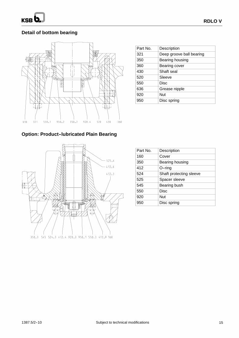
Detail of bottom bearing
Part No. Description321 Deep groove ball bearing350 Bearing housing360 Bearing cover430 Shaft seal520 Sleeve550 Disc636 Grease nipple920 Nut950 Disc spring
Option: Product--lubricated Plain Bearing
Part No. Description160 Cover350 Bearing housing412 O--ring524 Shaft protecting sleeve525 Spacer sleeve545 Bearing bush550 Disc920 Nut950 Disc spring

RDLO / RDLO V
16 1387.5/2--10Subject to technical modifications
Option: Gland Packing≥ 7 bar
Part No. Description211 Pump shaft441 Shaft seal housing452 Gland457 Neck ring461 Packing ring524 Shaft protecting sleeve
Option: Mechanical Seal (balanced)
Part No. Description211 Pump shaft412 O--ring433 Mechanical seal441 Shaft seal housing457 Neck ring471 Seal cover524 Shaft protecting sleeve
Option: Impeller with impeller wear ring
Part No. Description234 Double--entry impeller502 Casing wear ring503 Impeller wear ring904 Grub screw

RDLO / RDLO V
171387.5/2--10 Subject to technical modifications
Noise Characteristics for Pumps without MotorSound pressure level LpA
72
77
82
87
92
100 1000 10000
Nominal power input PN [kW]
n = 1480 min--1
n = 1780 min--1
n = 715 min--1
n = 740 min--1
n = 985 min--1
n = 1180 min--1
Lp
A[d
B]
Measurement Surface Ratio Ls Sound Power Level LWA:Pump size LS [dB]
350--575
350--690
400--525 16
400--705
500--585
400--665
400--935
500--685
500--835
500--860 17
500--1015
500--1035
600--600
600--705
600--885
600--1075 18
700--980
Standardised Octave Spectrum:
Speed [min --1]Octave centre frequency
Speed [min --1]63 125 250 500 1000 2000 4000 8000
≤ 950 --6 --3 0 --2 --4 --8 --12 --16
up to 2000 --4 --3 --2 --1 --4 --8 --12 --16
LWA = LpA + LS [dB]

RDLO
18 1387.5/2--10Subject to technical modifications
Dimension Table RDLO 350 -- 575 bis 400 -- 935
Direction of rotation of pump:CLOCKWISE
Connections:-- 1M Pressure gauge G 1/2-- 6D Vent G 1-- 6B Drain G 1-- 8B Leakage G 1/2
-- 9A Sealing liquid outlet G 1-- 9E Sealing liquid inlet G 1/2-- 9D Sealing liquid vent G 1
Dimensions and Weights all dimensions in mm
Pump sizesNominal
diameters Pump dimensionsPump sizes
DN1 DN2 d1 l1 a1 a2 f h1 h2 h3 l2 l3 z 1)
350--575400 350 95
900 700956 720 1676
350--690400 350 95
900750
956900 475 550
720 16761100
400--525105 210
750 700998
900 475 550
747 1745
1100
400--665500 400
105 2101000 750
9981000 525 620
747 17451240
400--705500 400
95900 800
956900 450 570
720 16761140
400--93595
1050 1000956
1000 550 650720 1676
1300
Pump sizes Foot dimensions Weights in kg DimensionalPump sizesb1 d3 m1 m2 n1 n2 n3 n4 s Pump Water fill
Dimensionaldrawing
350--575780 630
2600 300 UA7 3030401350--690
780 630560 560 485 485
2750 370 UA7 3030501400--525
150 35 890 740560 560 485 485
352400 475 UA7 3030701
400--665150 35 890 740 35
3200 550 UA7 3030801400--705 750 630
640 640 565 5652800 500 UA7 3030601
400--935 840 690640 640 565 565
3100 600 UA7 30772011) z = clear height above the casing cover required for removing the rotor

RDLO
191387.5/2--10 Subject to technical modifications
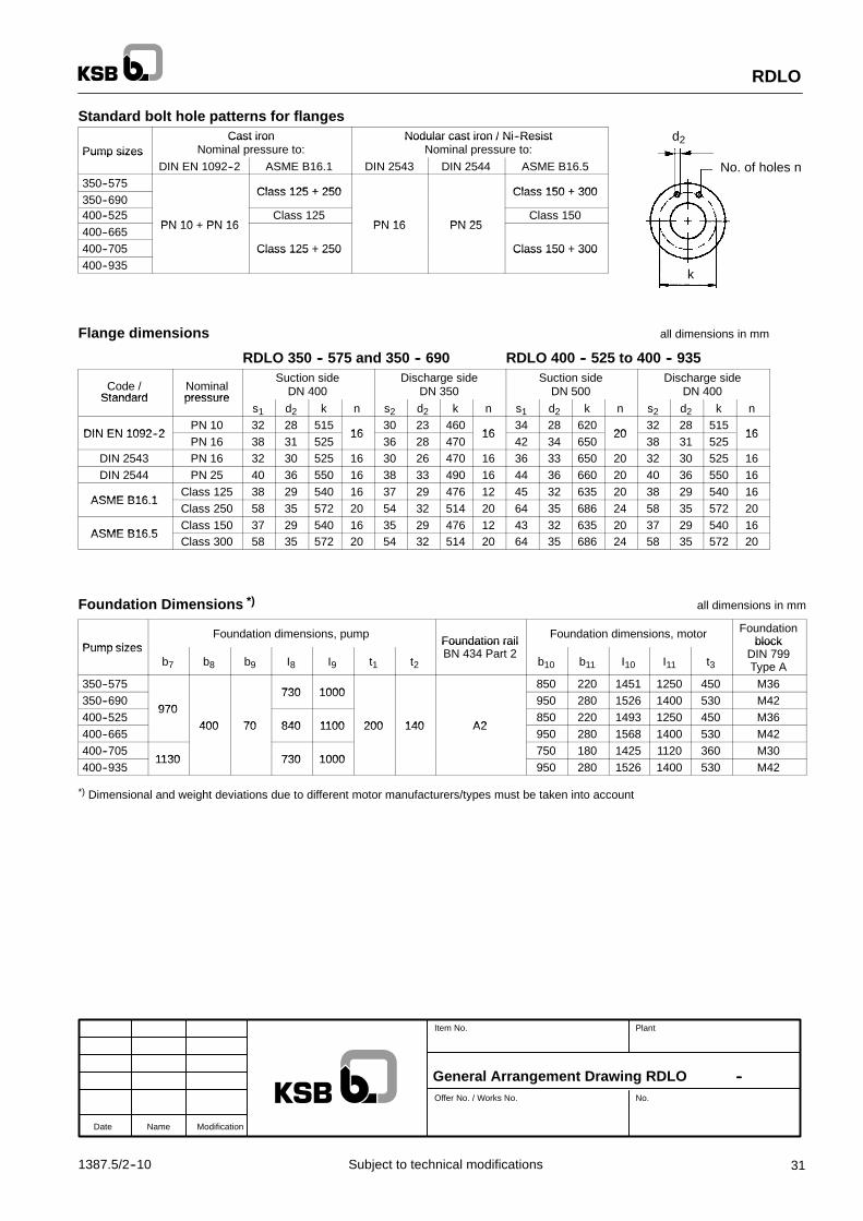
Standard bolt hole patterns for flanges
Pump sizesCast iron
Nominal pressure to:Nodular cast iron / Ni--Resist
Nominal pressure to:Pump sizesDIN EN 1092--2 ASME B16.1 DIN 2543 DIN 2544 ASME B16.5
350--575Class 125 + 250 Class 150 + 300
350--690Class 125 + 250 Class 150 + 300
400--525PN 10 + PN 16
Class 125PN 16 PN 25
Class 150400--665
PN 10 + PN 16 PN 16 PN 25
400--705 Class 125 + 250 Class 150 + 300400--935
Class 125 + 250 Class 150 + 300
Flange dimensionsRDLO 350--575 and 350--690 all dimensions in mm
Code /Standard
Nominalpressure
Suction sideDN 400
Discharge sideDN 350Standard pressure
s1 d2 k n s2 d2 k n
DIN EN 1092 2PN 10 32 28 515
1630 23 460
16DIN EN 1092--2PN 16 38 31 525
1636 28 470
16
DIN 2543 PN 16 32 30 525 16 30 26 470 16DIN 2543 PN 16 32 30 525 16 30 26 470 16DIN 2544 PN 25 40 36 550 16 38 33 490 16
ASME B16 1Class 125 38 29 540 16 37 29 476 12
ASME B16.1Class 250 58 35 572 20 54 32 514 20
ASME B16 5Class 150 37 29 540 16 35 29 476 12
ASME B16.5Class 300 58 35 572 20 54 32 514 20
RDLO 400--525 to 400--935 all dimensions in mm
Code /Standard
Nominalpressure
Suction sideDN 500
Discharge sideDN 400Standard pressure
s1 d2 k n s2 d2 k n
DIN EN 1092 2PN 10 34 28 620
2032 28 515
16DIN EN 1092--2PN 16 42 34 650
2038 31 525
16
DIN 2543 PN 16 36 33 650 20 32 30 525 16DIN 2543 PN 16 36 33 650 20 32 30 525 16DIN 2544 PN 25 44 36 660 20 40 36 550 16
ASME B16 1Class 125 45 32 635 20 38 29 540 16
ASME B16.1Class 250 64 35 686 24 58 35 572 20
ASME B16 5Class 150 43 32 635 20 37 29 540 16
ASME B16.5Class 300 64 35 686 24 58 35 572 20
k
d2
No. of holes n
Date Name Modification
Item No. Plant
Offer No. / Works No. No.
Dimension Table RDLO --

RDLO
20 1387.5/2--10Subject to technical modifications
Dimension Table RDLO 500 -- 585 to 500 -- 1035
Direction of rotation of pump:CLOCKWISE
Connections:-- 1M Pressure gauge G 1/2-- 6D Vent G 1-- 6B Drain G 1-- 8B Leakage G 1/2
-- 9A Sealing liquid outlet G 1-- 9E Sealing liquid inlet G 1/2-- 9D Sealing liquid vent G 1
Dimensions and Weights all dimensions in mm
Pump sizesNominal
diametersShaft Pump dimensions
Pump sizesDN1 DN2 d1 l1 a1 a2 f h1 h2 h3 l2 l3 z 1)
500--585105 210 1100 800 1098
550 680847 1945
1360500--685
105 210 1100 800 10981100
575670
847 19451340
500--835600 500
1150 11001100
575690 1380
500--860600 500
125 250 1200900
1166700 775
872 20381550
500--1015125 250 1200
11001166
1200 725 750872 2038
1500500--1035 1250
11001200
700 800 1600
Pump sizesFoot dimensions Weights in kg Dimensional
d iPump sizesb1 d3 m1 m2 n1 n2 n3 n4 s Pump Water fill
Dimensionaldrawing
500--585150 35 1050 900 640 640 565 565 35
4400 490 UA7 3030901500--685
150 35 1050 900 640 640 565 565 354300 700 UA7 3031001
500--835 850 850 750 750 4760 800 UA7 3042101500--860
200 42 1070 870725 725 625 625
405000 1000 UA7 3042301
500--1015200 42 1070 870
850 850 750 75040
5500 1100 UA7 3042201500--1035
850 850 750 7505680 1310 UA7 3042401
1) z = clear height above the casing cover required for removing the rotor

RDLO
211387.5/2--10 Subject to technical modifications
Standard bolt hole patterns for flanges
Pump sizesCast iron
Nominal pressure to:Nodular cast iron / Ni--Resist
Nominal pressure to:Pump sizesDIN EN 1092--2 ASME B16.1 DIN 2543 DIN 2544 ASME B16.5
500--585 PN 10 Class 125 PN 10 -- Class 150500--685 --500--835500--860 PN 10 + PN 16 Class 125 + 250 PN 16
PN 25Class 150 + 300
500--1015PN 10 + PN 16 Class 125 + 250 PN 16
PN 25Class 150 + 300
500--1035
Flange dimensions all dimensions in mm
Code /Standard
Nominalpressure
Suction sideDN 600
Discharge sideDN 500Standard pressure
s1 d2 k n s2 d2 k n
DIN EN 1092 2PN 10 36 31 725
2034 28 620
20DIN EN 1092--2PN 16 48 37 770
2042 34 650
20
DIN 2543 PN 16 40 36 770 20 36 33 650 20DIN 2543 PN 16 40 36 770 20 36 33 650 20DIN 2544 PN 25 46 39 770 20 44 36 660 20
ASME B16 1Class 125 48 35 749 20 45 32 635 20
ASME B16.1Class 250 70 42 813 24 64 35 686 24
ASME B16 5Class 150 48 35 749 20 43 32 635 20
ASME B16.5Class 300 70 42 813 24 64 35 686 24
k
d2
No. of holes n
Date Name Modification
Item No. Plant
Offer No. / Works No. No.
Dimension Table RDLO --
RDLO
22 1387.5/2--10Subject to technical modifications
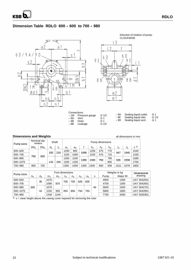
Dimension Table RDLO 600 -- 600 to 700 -- 980
Direction of rotation of pump:CLOCKWISE
Connections:-- 1M Pressure gauge G 1/2-- 6D Vent G 1-- 6B Drain G 1-- 8B Leakage G 1/2
-- 9A Sealing liquid outlet G 1-- 9E Sealing liquid inlet G 1/2-- 9D Sealing liquid vent G 1
Dimensions and Weights all dimensions in mm
Pump sizesNominal dia-
meters Shaft Pump dimensionsPump sizes
DN1 DN2 d1 l1 a1 a2 f h1 h2 h3 l2 l3 z 1)
600--600105 210
1200 9001098
1200 675 770847 1945
1540600--705
700 600105 210
1150 10001098
1100 575 715847 1945
1430600--885
700 6001300 1100
1280 1300 750790
926 22061580
600--1075 145 290 1250 12001280 1300 750
850926 2206
1700700--980 800 700
145 2901300 1050 1365 1500 850 930 1011 2376 1800
Pump sizesFoot dimensions Weights in kg DimensionalPump sizes
b1 d3 m1 m2 n1 n2 n3 n4 s Pump Water fillDimensional
drawing
600--60035
1070725 725 625 625
4900 1300 UA7 3042501600--705
351090 870
725 725 625 6254700 1300 UA7 3042601
600--885 200 1070870
40 5600 1500 UA7 3042701600--1075
20042 1150 950 850 850 750 750
405800 1800 UA7 3042801
700--98042
1340 1140850 750 750
7700 2000 UA7 30303011) z = clear height above the casing cover required for removing the rotor

RDLO
231387.5/2--10 Subject to technical modifications
Standard bolt hole patterns for flanges
Pump sizesCast iron
Nominal pressure to:Nodular cast iron / Ni--Resist
Nominal pressure to:Pump sizesDIN EN 1092--2 ASME B16.1 1) DIN 2543 DIN 2544 ASME B16.5 1)
600--600 PN 10 Class 125 PN 10600--705 -- Class 150600--885
PN 10 + PN 16 Class 125 + 250 PN 16
Class 150
600--1075PN 10 + PN 16 Class 125 + 250 PN 16
PN 25Class 150 + 300
700--980 --Class 150 + 300
1) Bolt hole pattern for DN 700 and above according to MSS SP44 and/or ASME B 16.47 Series A
Flange dimensionsRDLO 600--600 to 600--1075 all dimensions in mm
Code /Standard
Nominalpressure
Suction sideDN 700
Discharge sideDN 600Standard pressure
s1 d2 k n s2 d2 k n
DIN EN 1092 2PN 10 40 31
840 2436 31 725
20DIN EN 1092--2PN 16 54 37
840 2448 37 770
20
DIN 2543 PN 16 42 36 840 24 40 36 770 20DIN 2544 PN 25 50 42 875 24 46 39 770 20
ASME B16 1Class 125 48 35 749 20
ASME B16.1Class 250
-- -- -- --70 42 813 24
ASME B16 5Class 150 48 35 749 20
ASME B16.5Class 300
-- -- -- --70 42 813 24
MSS SP44Class 150 54 35 864
28-- -- -- --
MSS SP44Class 300 75 45 940
28-- -- -- --
RDLO 700--980 all dimensions in mm
Code /Standard
Nominalpressure
Suction sideDN 800
Discharge sideDN 700Standard pressure
s1 d2 k n s2 d2 k n
DIN EN 1092 2PN 10 44 34
950 2440 31
840 24DIN EN 1092--2PN 16 58 41
950 2454 37
840 24
DIN 2543 PN 16 42 39 950 24 42 36 840 24DIN 2544 PN 25 54 48 990 24 50 42 875 24
MSS SP44Class 150 59 41 978
2854 35 864
28MSS SP44Class 300 78 51 1054
2875 45 940
28
k
d2
No. of holes n
Date Name Modification
Item No. Plant
Offer No. / Works No. No.
Dimension Table RDLO --

RDLO V
24 1387.5/2--10Subject to technical modifications
Dimension Table RDLO V 350 -- 575 to 400 -- 935
Connections:-- 1M Pressure gauge G 1/2-- 6D Vent G 1-- 6B Drain G 1-- 9A Sealing liquid outlet G 1-- 9E Sealing liquid inlet G 1/2-- 8A1 Leakage G 1/2-- 8A2 Leakage G1
Direction ofrotation of pump:CLOCKWISE
Dimensions and Weights all dimensions in mm
Pump sizesNominal
diameters Shaft Pump dimensionsPump sizes
DN1 DN2 d1 l1 a1 a2 h2 h3 h4 h5
350--575400 350 95 900
700880 1841
350--690400 350 95 900
750 475 550880 1841
400--525105 210
750 700915 1918
400--665500 400
105 2101000 750 525 620
915 1918
400--705500 400
95900 800 450 570 875 1836
400--93595
1050 1000 550 650 880 1841
Foot dimensions Weights in kgDimensional
Pump sizesm3 m4 m5 m6 m7 n5 n6 n7 n8 n9 Pump Water fill Base-
plate
Dimensionaldrawing
350--575 2600 300 UA73043401
350--690 965 915 255 345 2750 370 UA73043501
400--5251340 1530 1130 1100 900 525
2400 475255
UA73043701
400--6651340
1065 1015 355 2451530 1130 1100 900 525
3200 550255
UA73043801
400--705 965 915 255 345 2800 500 UA73043601
400--935 1065 1015 355 245 3100 600 UA73077101

RDLO V
251387.5/2--10 Subject to technical modifications
Standard bolt hole patterns for flanges
Pump sizesCast iron
Nominal pressure to:Nodular cast iron / Ni--Resist
Nominal pressure to:Pump sizesDIN EN 1092--2 ASME B16.1 DIN 2543 DIN 2544 ASME B16.5
350--575Class 125 + 250 Class 150 + 300
350--690Class 125 + 250 Class 150 + 300
400--525PN 10 + PN 16
Class 125PN 16 PN 25
Class 150400--665
PN 10 + PN 16 PN 16 PN 25
400--705 Class 125 + 250 Class 150 + 300400--935
Class 125 + 250 Class 150 + 300
Flange dimensionsRDLO 350--575 and 350--690 all dimensions in mm
Code /Standard
Nominalpressure
Suction sideDN 400
Discharge sideDN 350Standard pressure
s1 d2 k n s2 d2 k n
DIN EN 1092 2PN 10 32 28 515
1630 23 460
16DIN EN 1092--2PN 16 38 31 525
1636 28 470
16
DIN 2543 PN 16 32 30 525 16 30 26 470 16DIN 2543 PN 16 32 30 525 16 30 26 470 16DIN 2544 PN 25 40 36 550 16 38 33 490 16
ASME B16 1Class 125 38 29 540 16 37 29 476 12
ASME B16.1Class 250 58 35 572 20 54 32 514 20
ASME B16 5Class 150 37 29 540 16 35 29 476 12
ASME B16.5Class 300 58 35 572 20 54 32 514 20
RDLO 400--525 to 400--935 all dimensions in mm
Code /Standard
Nominalpressure
Suction sideDN 500
Discharge sideDN 400Standard pressure
s1 d2 k n s2 d2 k n
DIN EN 1092 2PN 10 34 28 620
2032 28 515
16DIN EN 1092--2PN 16 42 34 650
2038 31 525
16
DIN 2543 PN 16 36 33 650 20 32 30 525 16DIN 2543 PN 16 36 33 650 20 32 30 525 16DIN 2544 PN 25 44 36 660 20 40 36 550 16
ASME B16 1Class 125 45 32 635 20 38 29 540 16
ASME B16.1Class 250 64 35 686 24 58 35 572 20
ASME B16 5Class 150 43 32 635 20 37 29 540 16
ASME B16.5Class 300 64 35 686 24 58 35 572 20
k
d2
No. of holes n
Date Name Modification
Item No. Plant
Offer No. / Works No. No.
Dimension Table RDLO V --

RDLO V
26 1387.5/2--10Subject to technical modifications
Dimension Table RDLO V 500 -- 585 to 500 -- 1035
Connections:-- 1M Pressure gauge G 1/2-- 6D Vent G 1-- 6B Drain G 1-- 9A Sealing liquid outlet G 1-- 9E Sealing liquid inlet G 1/2-- 8A1 Leakage G 1/2-- 8A2 Leakage G1
Direction ofrotation of pump:CLOCKWISE
Dimension and Weights all dimensions in mm
Pump sizesNominal
diameters Shaft Pump dimensionsPump sizes
DN1 DN2 d1 l1 a1 a2 h2 h3 h4 h5
500--585105 210 1100 800
550 6801015 2113
500--685105 210 1100 800
575670
1015 2113
500--835600 500
1150 1100575
690
500--860600 500
125 250 1200900 700 775
1000 2166500--1015
125 250 1200
1100725 750
1000 2166
500--1035 12501100
700 800
Foot dimensions Weights in kgDimensional
Pump sizesm3 m4 m5 m6 m7 n5 n6 n7 n8 n9 Pump Water fill Base-
plate
Dimensionaldrawing
500--5851650 1250 525
4400 490276
UA73043901
500--685 1165 1115 355 3651650 1250 525
4300 700276
UA73044001
500--8351560 1100 900
4760 800 UA73076201
500--8601560
1900 1500
1100 900
5805000 1000
292UA73076401
500--1015 1265 1215 455 2651900 1500 580
5500 1100292
UA73076301
500--1035 5680 1310 UA73076501

RDLO V
271387.5/2--10 Subject to technical modifications
Standard bolt hole patterns for flanges
Pump sizesCast iron
Nominal pressure to:Nodular cast iron / Ni--Resist
Nominal pressure to:Pump sizesDIN EN 1092--2 ASME B16.1 DIN 2543 DIN 2544 ASME B16.5
500--585 PN 10 Class 125 PN 10 -- Class 150500--685 --500--835500--860 PN 10 + PN 16 Class 125 + 250 PN 16
PN 25Class 150 + 300
500--1015PN 10 + PN 16 Class 125 + 250 PN 16
PN 25Class 150 + 300
500--1035
Flange dimensions all dimensions in mm
Code /Standard
Nominalpressure
Suction sideDN 600
Discharge sideDN 500Standard pressure
s1 d2 k n s2 d2 k n
DIN EN 1092 2PN 10 36 31 725
2034 28 620
20DIN EN 1092--2PN 16 48 37 770
2042 34 650
20
DIN 2543 PN 16 40 36 770 20 36 33 650 20DIN 2543 PN 16 40 36 770 20 36 33 650 20DIN 2544 PN 25 46 39 770 20 44 36 660 20
ASME B16 1Class 125 48 35 749 20 45 32 635 20
ASME B16.1Class 250 70 42 813 24 64 35 686 24
ASME B16 5Class 150 48 35 749 20 43 32 635 20
ASME B16.5Class 300 70 42 813 24 64 35 686 24
k
d2
No. of holes n
Date Name Modification
Item No. Plant
Offer No. / Works No. No.
Dimension Table RDLO V --

RDLO V
28 1387.5/2--10Subject to technical modifications
Dimension Table RDLO V 600 -- 600 to 700 -- 980
Connections:-- 1M Pressure gauge G 1/2-- 6D Vent G 1-- 6B Drain G 1-- 9A Sealing liquid outlet G 1-- 9E Sealing liquid inlet G 1/2-- 8A1 Leakage G 1/2-- 8A2 Leakage G1
Direction ofrotation of pump:CLOCKWISE
Dimensions and Weights all dimensions in mm
Pump sizesNominal
diameters Shaft Pump dimensionsPump sizes
DN1 DN2 d1 l1 a1 a2 h2 h3 h4 h5
600--600105 210
1200 900 675 7701015 2113
600--705700 600
105 2101150 1000 575 715
1015 2113
600--885700 600
1300 1100750
7901040 2320
600--1075 145 290 1250 1200750
8501040 2320
700--980 800 700 1300 1050 850 930 1125 2490
Foot dimensions Weights in kgDimensional
Pump sizesm3 m4 m5 m6 m7 n5 n6 n7 n8 n9 Pump Water fill Base-
plate
Dimensionaldrawing
600--6001560
1265 1215 455 2651650 1250 525
4900 1300273
UA73076601
600--7051560
1165 1115 355 3651650 1250 525
4700 1300273
UA73076701
600--8851365 1315 270 480
1100 900 5600 1500 UA73076801
600--1075 18751365 1315 270 480
1900 1500 580 5800 1800 310 UA73076901
700--980 1565 1515 470 280 7700 2000 UA73043301

RDLO V
291387.5/2--10 Subject to technical modifications
Standard bolt hole patterns for flanges
Pump sizesCast iron
Nominal pressure to:Nodular cast iron / Ni--Resist
Nominal pressure to:Pump sizesDIN EN 1092--2 ASME B16.1 1) DIN 2543 DIN 2544 ASME B16.5 1)
600--600 PN 10 Class 125 PN 10600--705 -- Class 150600--885
PN 10 + PN 16 Class 125 + 250 PN 16
Class 150
600--1075PN 10 + PN 16 Class 125 + 250 PN 16
PN 25Class 150 + 300
700--980 --Class 150 + 300
1) Bolt hole pattern for DN 700 and above according to MSS SP44 and/or ASME B 16.47 Series A
Flange dimensionsRDLO 600--600 to 600--1075 all dimensions in mm
Code /Standard
Nominalpressure
Suction sideDN 700
Discharge sideDN 600Standard pressure
s1 d2 k n s2 d2 k n
DIN EN 1092 2PN 10 40 31
840 2436 31 725
20DIN EN 1092--2PN 16 54 37
840 2448 37 770
20
DIN 2543 PN 16 42 36 840 24 40 36 770 20DIN 2544 PN 25 50 42 875 24 46 39 770 20
ASME B16 1Class 125 48 35 749 20
ASME B16.1Class 250
-- -- -- --70 42 813 24
ASME B16 5Class 150 48 35 749 20
ASME B16.5Class 300
-- -- -- --70 42 813 24
MSS SP44Class 150 54 35 864
28-- -- -- --
MSS SP44Class 300 75 45 940
28-- -- -- --
RDLO 700--980 all dimensions in mm
Code /Standard
Nominalpressure
Suction sideDN 800
Discharge sideDN 700Standard pressure
s1 d2 k n s2 d2 k n
DIN EN 1092 2PN 10 44 34
950 2440 31
840 24DIN EN 1092--2PN 16 58 41
950 2454 37
840 24
DIN 2543 PN 16 42 39 950 24 42 36 840 24DIN 2544 PN 25 54 48 990 24 50 42 875 24
MSS SP44Class 150 59 41 978
2854 35 864
28MSS SP44Class 300 78 51 1054
2875 45 940
28
k
d2
No. of holes n
Date Name Modification
Item No. Plant
Offer No. / Works No. No.
Dimension Table RDLO V --

RDLO
30 1387.5/2--10Subject to technical modifications
General Arrangement Drawing RDLO 350 -- 575 to 400 -- 935
Type of installation 2E
Direction of rotation of pump ”CLOCKWISE”
Top layer concrete
Dimensions and Weights *) all dimensions in mm
Pump sizesNominal
diameters Pump set dimensionsPump sizes
DN1 DN2 a1 a2 f h1 h2 h3
350--575400 350 900
700956
350--690400 350 900
750956
900 475 550
400--525 750 700998
400--665500 400
1000 750998
1000 525 620
400--705500 400
900 800956
900 450 570
400--935 1050 1000956
1000 550 650
Pump sizesPump set dimensions Weights in kg
Pump sizesh12 h13 h14 l2 q l7 m1 z 1) Pump Water fill Motor
350--575 1135 500 400720
2345 4026780
2600 300 5200
350--690 1250 560 340720
2600 4281780
1100 2750 370 7000
400--525 1135 500 400747
2345 4095890
2400 475 5500
400--665 1250 560 440747
2600 4350890
1240 3200 550 7300
400--705 1050 450 450720
2165 3846 750 1140 2800 500 3800
400--935 1250 560 440720
2600 4281 840 1300 3100 600 8100
*) Dimensional and weight deviations due to different motor manufacturers/types must be taken into account1) z = clear height above the casing cover required for removing the rotor
Connecting flange:-- All flanges are designed as plate flanges-- Connect the pipes without transmitting any stresses or strains
Permissible forces and moments acting onthe pump nozzles, see table on page 9
For the position of the terminal box please refer to themotor dimensional drawing
k
d2
No. of holes n
RDLO
311387.5/2--10 Subject to technical modifications
Standard bolt hole patterns for flangesCast iron Nodular cast iron / Ni--Resist
Pump sizesCast iron
Nominal pressure to:Nodular cast iron / Ni Resist
Nominal pressure to:Pump sizesDIN EN 1092--2 ASME B16.1 DIN 2543 DIN 2544 ASME B16.5
350--575Class 125 + 250 Class 150 + 300
350--690Class 125 + 250 Class 150 + 300
400--525PN 10 PN 16
Class 125PN 16 PN 25
Class 150400--665
PN 10 + PN 16 PN 16 PN 25
400--705 Class 125 + 250 Class 150 + 300400--935
Class 125 + 250 Class 150 + 300
Flange dimensions all dimensions in mm
RDLO 350 -- 575 and 350 -- 690 RDLO 400 -- 525 to 400 -- 935
Code /Standard
Nominalpressure
Suction sideDN 400
Discharge sideDN 350
Suction sideDN 500
Discharge sideDN 400Standard pressure
s1 d2 k n s2 d2 k n s1 d2 k n s2 d2 k n
DIN EN 1092 2PN 10 32 28 515
1630 23 460
1634 28 620
2032 28 515
16DIN EN 1092--2PN 16 38 31 525
1636 28 470
1642 34 650
2038 31 525
16
DIN 2543 PN 16 32 30 525 16 30 26 470 16 36 33 650 20 32 30 525 16DIN 2544 PN 25 40 36 550 16 38 33 490 16 44 36 660 20 40 36 550 16
ASME B16 1Class 125 38 29 540 16 37 29 476 12 45 32 635 20 38 29 540 16
ASME B16.1Class 250 58 35 572 20 54 32 514 20 64 35 686 24 58 35 572 20
ASME B16 5Class 150 37 29 540 16 35 29 476 12 43 32 635 20 37 29 540 16
ASME B16.5Class 300 58 35 572 20 54 32 514 20 64 35 686 24 58 35 572 20
Foundation Dimensions *) all dimensions in mm
Pump sizesFoundation dimensions, pump
Foundation railFoundation dimensions, motor Foundation
blockPump sizesb7 b8 b9 I8 I9 t1 t2
Foundation railBN 434 Part 2
b10 b11 I10 I11 t3
blockDIN 799Type A
350--575730 1000
850 220 1451 1250 450 M36350--690
970730 1000
950 280 1526 1400 530 M42400--525
970400 70 840 1100 200 140 A2
850 220 1493 1250 450 M36400--665
400 70 840 1100 200 140 A2950 280 1568 1400 530 M42
400--7051130 730 1000
750 180 1425 1120 360 M30400--935
1130 730 1000950 280 1526 1400 530 M42
*) Dimensional and weight deviations due to different motor manufacturers/types must be taken into account
Date Name Modification
Item No. Plant
Offer No. / Works No. No.
General Arrangement Drawing RDLO --

RDLO
32 1387.5/2--10Subject to technical modifications
General Arrangement Drawing RDLO 500 -- 585 to 500 -- 1035
Type of installation 2E
Direction of rotation of pump ”CLOCKWISE”
Top layer concrete
Dimensions and Weights *) all dimensions in mm
Pump sizesNominal
diameters Pump set dimensionsPump sizes
DN1 DN2 a1 a2 f h1 h2 h3
500--5851100 800 1098
550 680500--685
1100 800 10981100
575670
500--835600 500
1150 11001100
575690
500--860600 500
1200900
1166700 775
500--10151200
11001166
1200 725 750
500--1035 12501100
1200700 800
Pump sizesPump set dimensions Weights in kg
Pump sizesh12 h13 h14 l2 q l7 m1 z 1) Pump Water fill Motor
500--585 1135 500 600847
2385 43351050
1360 4400 490 5100500--685 1250
540
8472600 4550
10501340 4300 700 7500
500--835540
2950 49931380 4760 800 8100
500--860 2260560
872
2950 49931070 1550 5000 1000 8650
500--10152260
640872
3180 52231500 5500 1100
10050500--1035
3180 52231600 5680 1310
10050
*) Dimensional and weight deviations due to different motor manufacturers/types must be taken into account1) z = clear height above the casing cover required for removing the rotor
Connecting flange:-- All flanges are designed as plate flanges-- Connect the pipes without transmitting any stresses or strains
Permissible forces and moments acting onthe pump nozzles, see table on page 9
For the position of the terminal box please refer to themotor dimensional drawing

RDLO
331387.5/2--10 Subject to technical modifications
Standard bolt hole patterns for flanges
Pump sizesCast iron
Nominal pressure to:Nodular cast iron / Ni--Resist
Nominal pressure to:Pump sizesDIN EN 1092--2 ASME B16.1 DIN 2543 DIN 2544 ASME B16.5
500--585 PN 10 Class 125 PN 10 -- Class 150500--685 --500--835500--860 PN 10 + PN 16 Class 125 + 250 PN 16
PN 25Class 150 + 300
500--1015PN 10 + PN 16 Class 125 + 250 PN 16
PN 25Class 150 + 300
500--1035
Flange dimensions all dimensions in mm
Code /Standard
Nominalpressure
Suction sideDN 600
Discharge sideDN 500Standard pressure
s1 d2 k n s2 d2 k n
DIN EN 1092 2PN 10 36 31 725
2034 28 620
20DIN EN 1092--2PN 16 48 37 770
2042 34 650
20
DIN 2543 PN 16 40 36 770 20 36 33 650 20DIN 2543 PN 16 40 36 770 20 36 33 650 20DIN 2544 PN 25 46 39 770 20 44 36 660 20
ASME B16 1Class 125 48 35 749 20 45 32 635 20
ASME B16.1Class 250 70 42 813 24 64 35 686 24
ASME B16 5Class 150 48 35 749 20 43 32 635 20
ASME B16.5Class 300 70 42 813 24 64 35 686 24
Foundation Dimensions *) all dimensions in mm
Pump sizesFoundation dimensions, pump
Foundation railFoundation dimensions, pump Foundation
blockPump sizesb7 b8 b9 I8 I9 t1 t2
Foundation railBN 434 Part 2
b10 b11 I10 I11 t3
blockDIN 799Type A
500--5851130 400 1000 A2
850 220 1633 1250 450 M36500--685
1130 400 1000 A2950 1668
500--835 150070 1300 200 140
1400500--860 1250
50070
9701300 200 140
A4 1060280
1726
1400530 M42
500--10151500
500 970 A4 1060280
17261600
530 M42
500--10351500 1600
*) Dimensional and weight deviations due to different motor manufacturers/types must be taken into account
k
d2
No. of holes n
Date Name Modification
Item No. Plant
Offer No. / Works No. No.
General Arrangement Drawing RDLO --

RDLO
34 1387.5/2--10Subject to technical modifications
General Arrangement Drawing RDLO 600 -- 600 to 700 -- 980
Type of installation 2E
Direction of rotation of pump ”CLOCKWISE”
Top layer concrete
Dimensions and Weights *) all dimensions in mm
Pump sizesNominal
diameters Pump set dimensionsPump sizes
DN1 DN2 a1 a2 f h1 h2 h3
600--600 1200 9001098
1200 675 770600--705
700 6001150 1000
10981100 575 715
600--885700 600
1300 11001280 1300 750
790600--1075 1250 1200
1280 1300 750850
700--980 800 700 1300 1050 1365 1500 850 930
Pump sizesPump set dimensions Weights in kg
Pump sizesh12 h13 h14 l2 q l7 m1 z 1) Pump Water fill Motor
600--600 1135 500 700847
2385 4335 1070 1540 4900 1300 5100
600--705 1250 540847
2600 4550 1090 1430 4700 1300 8100
600--885560 926
2950 5161 1070 1580 5600 1500 8650
600--1075 2260560 740 926
5391 1150 1700 5800 180010050
700--980 940 1011 3180 5561 1340 1800 7700 200010050
*) Dimensional and weight deviations due to different motor manufacturers/types must be taken into account1) z = clear height above the casing cover required for removing the rotor
Connecting flange:-- All flanges are designed as plate flanges-- Connect the pipes without transmitting any stresses or strains
Permissible forces and moments acting onthe pump nozzles, see table on page 9
For the position of the terminal box please refer to themotor dimensional drawing

k
d2
No. of holes n
RDLO
351387.5/2--10 Subject to technical modifications
Standard bolt hole patterns for flangesCast iron Nodular cast iron / Ni--Resist
Pump sizesCast iron
Nominal pressure to:Nodular cast iron / Ni Resist
Nominal pressure to:Pump sizesDIN EN 1092--2 ASME B16.1 1) DIN 2543 DIN 2544 ASME B16.5 1)
600--600 PN 10 Class 125 PN 10600--705 -- Class 150600--885
PN 10 + PN 16 Class 125 + 250 PN 16600--1075
PN 10 + PN 16 Class 125 + 250 PN 16PN 25
Class 150 + 300700--980 --
Class 150 + 300
1) Bolt hole pattern for DN 700 and above according to MSS SP44 and/or ASME B16.47 Series A
Flange dimensions all dimensions in mm
RDLO 600 -- 600 to 600 -- 1075 RDLO 700 -- 980
Code /Standard Nom
Suction sideDN 700
Discharge sideDN 600
Suction sideDN 800
Discharge sideDN 700Standard Nom
s1 d2 k n s2 d2 k n s1 d2 k n s2 d2 k n
DIN EN 1092 2PN 10 40 31
840 2436 31 725
2044 34
950 2440 31
840 24DIN EN 1092--2PN 16 54 37
840 2448 37 770
2058 41
950 2454 37
840 24
DIN 2543 PN 16 42 36 840 24 40 36 770 20 42 39 950 24 42 36 840 24DIN 2544 PN 25 50 42 875 24 46 39 770 20 54 48 990 24 50 42 875 24
ASME B16 1Class 125 48 35 749 20
ASME B16.1Class 250
-- -- -- --70 42 813 24
-- -- -- -- -- -- -- --
ASME B16 5Class 150 48 35 749 20
ASME B16.5Class 300
-- -- -- --70 42 813 24
-- -- -- -- -- -- -- --
MSS SP44Class 150 54 35 864
28-- -- -- -- 59 41 978
2854 35 864
28MSS SP44Class 300 75 45 940
28-- -- -- -- 78 51 1054
2875 45 940
28
Foundation Dimensions *) all dimensions in mm
Pump sizesFoundation dimensions, pump
Foundation railFoundation dimensions, motor Foundation
blockPump sizesb7 b8 b9 I8 I9 t1 t2
Foundation railBN 434 Part 2
b10 b11 I10 I11 t3
blockDIN 799Type A
600--6001250
850 220 1633 1250 450 M36600--705
1250970 1300 950 1668
1400600--885 500 70
970 1300200 140 A4
280 18401400
530 M42600--1075 1500
500 701050 1400
200 140 A41060
280 18401600
530 M42
700--9801500
1240 16001060
19251600
*) Dimensional and weight deviations due to different motor manufacturers/types must be taken into account
Date Name Modification
Item No. Plant
Offer No. / Works No. No.
General Arrangement Drawing RDLO --

RDLO
36 1387.5/2--10Subject to technical modifications
General Arrangement Drawing RDLO 350 -- 575 to 400 -- 935
Type of installation 3E
Direction of rotation of pump ”CLOCKWISE”
Top layer concrete
Connecting flange:-- All flanges are designed as plate flanges-- Connect the pipes without transmitting any stresses or strains
After aligning grout the baseplate with non--shrinking concrete!
For the position of the terminal box please refer to themotor dimensional drawing
Where appropriate, the pump sets are assembled completelyat the factory in order tocheck them for proper adjustment. Af-terwards they are disassembled for shipping, and the compo-nents are dispatched separately.
Permissible forces and moments acting onthe pump nozzles, see table on page 9
Dimensions *) all dimensions in mm
Pump sizesNominal
diameters Pump set dimensionsPump sizes
DN1 DN2 a1 a2 f h1 h2 h3 h8 h9 h10
350--575400 350 900
700956
350--690400 350 900
750956
900 475 550 1130 1680400--525 750 700
998
900 475 550
230
1130 1680
400--665500 400
1000 750998
1000 525 620230
1230 1850400--705
500 400900 800
956900 450 570 1130 1700
400--935 1050 1000956
1000 550 650 1230 1880
Pump sizesPump set dimensions
Pump sizesh11 i l2 q l7 m1 w1 z 1)
350--575 1765140 720
2345 4026780
350--690 1820140 720
2600 4281780
280 1100
400--525 1765 170747
2345 4095890
400--665 1920 195747
2600 4350890
252 1240
400--705 1730125
720 2165 3846 750295
1140
400--935 1920125
720 2600 4281 780295
1300
*) Dimensional and weight deviations due to different motor manufacturers/types must be taken into account1) z = clear height above the casing cover required for removing the rotor

k
d2
No. of holes n
RDLO
371387.5/2--10 Subject to technical modifications
Standard bolt hole patterns for flangesCast iron Nodular cast iron / Ni--Resist
Pump sizesCast iron
Nominal pressure to:Nodular cast iron / Ni Resist
Nominal pressure to:Pump sizesDIN EN 1092--2 ASME B16.1 DIN 2543 DIN 2544 ASME B16.5
350--575Class 125 + 250 Class 150 + 300
350--690Class 125 + 250 Class 150 + 300
400--525PN 10 PN 16
Class 125PN 16 PN 25
Class 150400--665
PN 10 + PN 16 PN 16 PN 25
400--705 Class 125 + 250 Class 150 + 300400--935
Class 125 + 250 Class 150 + 300
Flange dimensions all dimensions in mm
RDLO 350 -- 575 and 350 -- 690 RDLO 400 -- 525 to 400 -- 935
Code /Standard
Nominalpressure
Suction sideDN 400
Discharge sideDN 350
Suction sideDN 500
Discharge sideDN 400Standard pressure
s1 d2 k n s2 d2 k n s1 d2 k n s2 d2 k n
DIN EN 1092 2PN 10 32 28 515
1630 23 460
1634 28 620
2032 28 515
16DIN EN 1092--2PN 16 38 31 525
1636 28 470
1642 34 650
2038 31 525
16
DIN 2543 PN 16 32 30 525 16 30 26 470 16 36 33 650 20 32 30 525 16DIN 2544 PN 25 40 36 550 16 38 33 490 16 44 36 660 20 40 36 550 16
ASME B16 1Class 125 38 29 540 16 37 29 476 12 45 32 635 20 38 29 540 16
ASME B16.1Class 250 58 35 572 20 54 32 514 20 64 35 686 24 58 35 572 20
ASME B16 5Class 150 37 29 540 16 35 29 476 12 43 32 635 20 37 29 540 16
ASME B16.5Class 300 58 35 572 20 54 32 514 20 64 35 686 24 58 35 572 20
Foundation Dimensions and Weights *) all dimensions in mm
Foundation dimensions Weights in kgPump sizes
b4 b5 b6 l4 l5 l6 t Pump Water fill Motor Base-plate
350--575 950 3450 2600 300 5200 813350--690
1200800 3760 2750 370 7000 827
400--5251200
200 100 300950 3450
3202400 475 5500 813
400--665200 100 300
800 3760320
3200 550 7300 924400--705
1320875 3230 2800 500 3800 826
400--9351320
800 3760 3100 600 8100 945
*) Dimensional and weight deviations due to different motor manufacturers/types must be taken into account
Date Name Modification
Item No. Plant
Offer No. / Works No. No.
General Arrangement Drawing RDLO --

RDLO
38 1387.5/2--10Subject to technical modifications
General Arrangement Drawing RDLO 500 -- 585 to 500 -- 1035
Type of installation 3E
Direction of rotation of pump ”CLOCKWISE”
Top layer concrete
Connecting flange:-- All flanges are designed as plate flanges-- Connect the pipes without transmitting any stresses or strains
After aligning grout the baseplate with non--shrinking concrete!
For the position of the terminal box please refer to themotor dimensional drawing
Where appropriate, the pump sets are assembled completely at thefactory in order to check them for proper adjustment. Afterwards theyare disassembled for shipping, and the components are dispatchedseparately.
Permissible forces and moments acting onthe pump nozzles, see table on page 9
Dimensions *) all dimensions in mm
Pump sizesNominal
diameters Pump set dimensionsPump sizes
DN1 DN2 a1 a2 f h1 h2 h3 h8 h9 h10
500--5851100 800 1098
550 680 2010500--685
1100 800 10981100
575670 1330 2000
500--835600 500
1150 11001100
575690
230
13302020
500--860600 500
1200900
1166700 775
2302205
500--10151200
11001166
1200 725 750 1430 2180
500--1035 12501100
1200700 800
14302230
Pump sizesPump set dimensions
Pump sizesh11 i l2 q l7 m1 w1 z 1)
500--585 1965275 847
2385 43351050 272
1360
500--685 2020275 847
2600 45501050 272
1340
500--835 30302950 4993
1380
500--860285 872
2950 49931070 287
1550
500--1015 3130285 872
3180 5223
1070 2871500
500--10353180 5223
1600
*) Dimensional and weight deviations due to different motor manufacturers/types must be taken into account1) z = clear height above the casing cover required for removing the rotor

RDLO
391387.5/2--10 Subject to technical modifications
Standard bolt hole patterns for flanges
Pump sizesCast iron
Nominal pressure to:Nodular cast iron / Ni--Resist
Nominal pressure to:Pump sizesDIN EN 1092--2 ASME B16.1 DIN 2543 DIN 2544 ASME B16.5
500--585 PN 10 Class 125 PN 10 -- Class 150500--685 --500--835500--860 PN 10 + PN 16 Class 125 + 250 PN 16
PN 25Class 150 + 300
500--1015PN 10 + PN 16 Class 125 + 250 PN 16
PN 25Class 150 + 300
500--1035
Flange dimensions all dimensions in mm
Code /Standard
Nominalpressure
Suction sideDN 600
Discharge sideDN 500Standard pressure
s1 d2 k n s2 d2 k n
DIN EN 1092 2PN 10 36 31 725
2034 28 620
20DIN EN 1092--2PN 16 48 37 770
2042 34 650
20
DIN 2543 PN 16 40 36 770 20 36 33 650 20DIN 2543 PN 16 40 36 770 20 36 33 650 20DIN 2544 PN 25 46 39 770 20 44 36 660 20
ASME B16 1Class 125 48 35 749 20 45 32 635 20
ASME B16.1Class 250 70 42 813 24 64 35 686 24
ASME B16 5Class 150 48 35 749 20 43 32 635 20
ASME B16.5Class 300 70 42 813 24 64 35 686 24
Foundation Dimensions and Weights *) all dimensions in mm
Foundation dimensions Weights in kgPump sizes
b4 b5 b6 l4 l5 l6 t Pump Water fill Motor Base-plate
500--5851320
800 3760 4400 490 5100 1051
500--6851320
860 4060 4300 700 7500 1082
500--835 1740200 100 300
800 3800320
4760 800 8100 1189
500--860 1490200 100 300
860 4060
3205000 1000 8650 1230
500--10151740
860 40605500 1100
100501378
500--10351740
940 4350 5680 131010050
1409
*) Dimensional and weight deviations due to different motor manufacturers/types must be taken into account
k
d2
No. of holes n
Date Name Modification
Item No. Plant
Offer No. / Works No. No.
General Arrangement Drawing RDLO --
RDLO
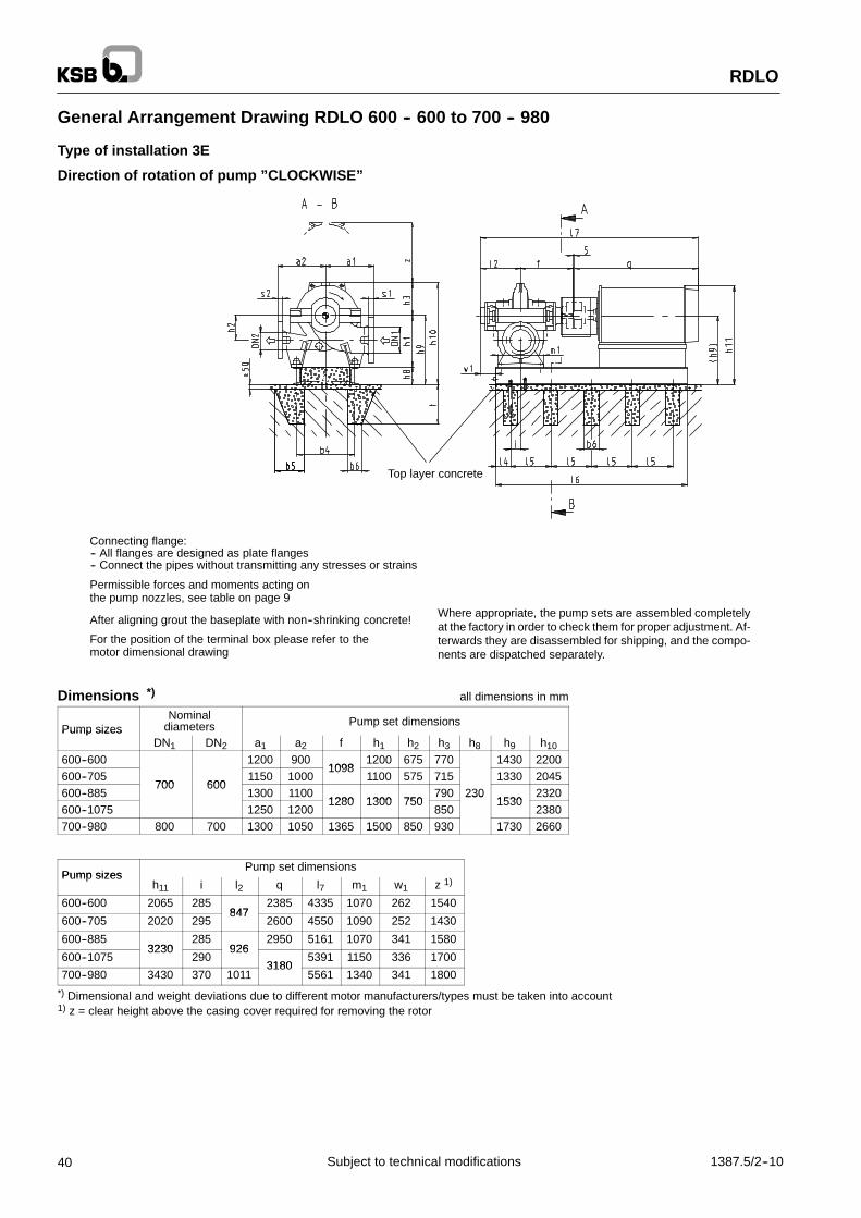
40 1387.5/2--10Subject to technical modifications
General Arrangement Drawing RDLO 600 -- 600 to 700 -- 980
Type of installation 3E
Direction of rotation of pump ”CLOCKWISE”
Top layer concrete
Connecting flange:-- All flanges are designed as plate flanges-- Connect the pipes without transmitting any stresses or strains
After aligning grout the baseplate with non--shrinking concrete!
For the position of the terminal box please refer to themotor dimensional drawing
Where appropriate, the pump sets are assembled completelyat the factory in order to check them for proper adjustment. Af-terwards they are disassembled for shipping, and the compo-nents are dispatched separately.
Permissible forces and moments acting onthe pump nozzles, see table on page 9
Dimensions *) all dimensions in mm
Pump sizesNominal
diameters Pump set dimensionsPump sizes
DN1 DN2 a1 a2 f h1 h2 h3 h8 h9 h10
600--600 1200 9001098
1200 675 770 1430 2200600--705
700 6001150 1000
10981100 575 715 1330 2045
600--885700 600
1300 11001280 1300 750
790 2301530
2320600--1075 1250 1200
1280 1300 750850
2301530
2380700--980 800 700 1300 1050 1365 1500 850 930 1730 2660
Pump sizesPump set dimensions
Pump sizesh11 i l2 q l7 m1 w1 z 1)
600--600 2065 285847
2385 4335 1070 262 1540
600--705 2020 295847
2600 4550 1090 252 1430
600--8853230
285926
2950 5161 1070 341 1580
600--10753230
290926
31805391 1150 336 1700
700--980 3430 370 10113180
5561 1340 341 1800
*) Dimensional and weight deviations due to different motor manufacturers/types must be taken into account1) z = clear height above the casing cover required for removing the rotor

k
d2
No. of holes n
RDLO
411387.5/2--10 Subject to technical modifications
Standard bolt hole patterns for flangesCast iron Nodular cast iron / Ni--Resist
Pump sizesCast iron
Nominal pressure to:Nodular cast iron / Ni Resist
Nominal pressure to:Pump sizesDIN EN 1092--2 ASME B16.1 1) DIN 2543 DIN 2544 ASME B16.5 1)
600--600 PN 10 Class 125 + 250 PN 10600--705 -- Class 150600--885
PN 10 + PN 16 Class 125 + 250 PN 16600--1075
PN 10 + PN 16 Class 125 + 250 PN 16PN 25 Class 150 + 300
700--980 -- Class 150
1) Bolt hole pattern for DN 700 and above according to MSS SP44 and/or ASME B16.47 Series A
Flange dimensions all dimensions in mm
RDLO 600 -- 600 to 600 -- 1075 RDLO 700 -- 980
Code /Standard Nom
Suction sideDN 700
Discharge sideDN 600
Suction sideDN 800
Discharge sideDN 700Standard Nom
s1 d2 k n s2 d2 k n s1 d2 k n s2 d2 k n
DIN EN 1092 2PN 10 40 31
840 2436 31 725
2044 34
950 2440 31
840 24DIN EN 1092--2PN 16 54 37
840 2448 37 770
2058 41
950 2454 37
840 24
DIN 2543 PN 16 42 36 840 24 40 36 770 20 42 39 950 24 42 36 840 24DIN 2544 PN 25 50 42 875 24 46 39 770 20 54 48 990 24 50 42 875 24
ASME B16 1Class 125 48 35 749 20
ASME B16.1Class 250
-- -- -- --70 42 813 24
-- -- -- -- -- -- -- --
ASME B16 5Class 150 48 35 749 20
ASME B16.5Class 300
-- -- -- --70 42 813 24
-- -- -- -- -- -- -- --
MSS SP44Class 150 54 35 864
28-- -- -- -- 59 41 978
2854 35 864
28MSS SP44Class 300 75 45 940
28-- -- -- -- 78 51 1054
2875 45 940
28
Foundation Dimensions and Weights *) all dimensions in mm
Foundation dimensions Weights in kgPump sizes
b4 b5 b6 l4 l5 l6 t Pump Water fill Motor Base-plate
600--6001490
800 3750 4900 1300 5100 1303
600--7051490
860 4060 4700 1300 8100 1264
600--885 200 100 300 875 4120 320 5600 1500 8650 1533
600--1075 1740955 4410
5800 1800 1640
700--980955 4410
7700 2000 10050 1861
*) Dimensional and weight deviations due to different motor manufacturers/types must be taken into account
Date Name Modification
Item No. Plant
Offer No. / Works No. No.
General Arrangement Drawing RDLO --
RDLO
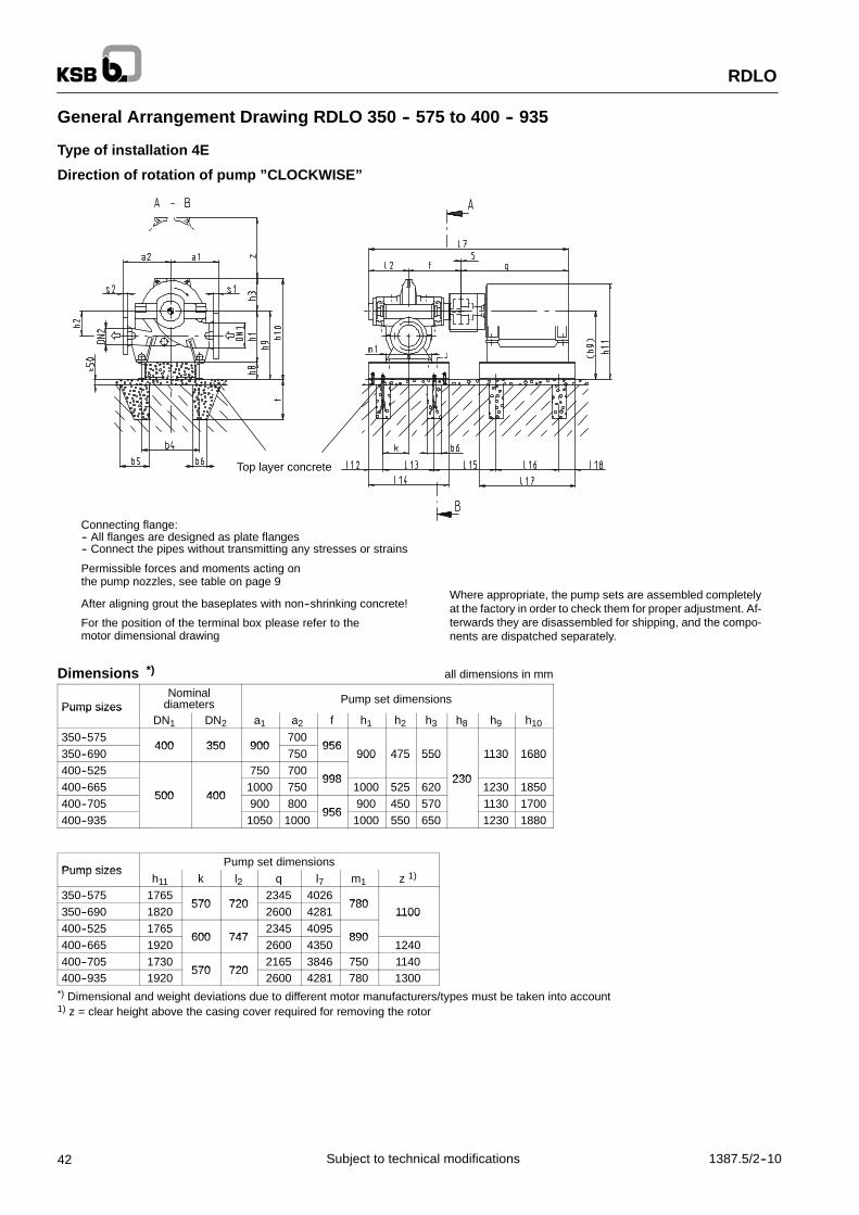
42 1387.5/2--10Subject to technical modifications
General Arrangement Drawing RDLO 350 -- 575 to 400 -- 935
Type of installation 4E
Direction of rotation of pump ”CLOCKWISE”
Top layer concrete
Connecting flange:-- All flanges are designed as plate flanges-- Connect the pipes without transmitting any stresses or strains
After aligning grout the baseplates with non--shrinking concrete!
For the position of the terminal box please refer to themotor dimensional drawing
Where appropriate, the pump sets are assembled completelyat the factory in order to check them for proper adjustment. Af-terwards they are disassembled for shipping, and the compo-nents are dispatched separately.
Permissible forces and moments acting onthe pump nozzles, see table on page 9
Dimensions *) all dimensions in mm
Pump sizesNominal
diameters Pump set dimensionsPump sizes
DN1 DN2 a1 a2 f h1 h2 h3 h8 h9 h10
350--575400 350 900
700956
350--690400 350 900
750956
900 475 550 1130 1680400--525 750 700
998
900 475 550
230
1130 1680
400--665500 400
1000 750998
1000 525 620230
1230 1850400--705
500 400900 800
956900 450 570 1130 1700
400--935 1050 1000956
1000 550 650 1230 1880
Pump sizesPump set dimensions
Pump sizesh11 k l2 q l7 m1 z 1)
350--575 1765570 720
2345 4026780
350--690 1820570 720
2600 4281780
1100400--525 1765
600 7472345 4095
890
1100
400--665 1920600 747
2600 4350890
1240400--705 1730
570 7202165 3846 750 1140
400--935 1920570 720
2600 4281 780 1300*) Dimensional and weight deviations due to different motor manufacturers/types must be taken into account1) z = clear height above the casing cover required for removing the rotor

k
d2
No. of holes n
RDLO
431387.5/2--10 Subject to technical modifications
Standard bolt hole patterns for flangesCast iron Nodular cast iron / Ni--Resist
Pump sizesCast iron
Nominal pressure to:Nodular cast iron / Ni Resist
Nominal pressure to:Pump sizesDIN EN 1092--2 ASME B16.1 DIN 2543 DIN 2544 ASME B16.5
350--575Class 125 + 250 Class 150 + 300
350--690Class 125 + 250 Class 150 + 300
400--525PN 10 PN 16
Class 125PN 16 PN 25
Class 150400--665
PN 10 + PN 16 PN 16 PN 25
400--705 Class 125 + 250 Class 150 + 300400--935
Class 125 + 250 Class 150 + 300
Flange dimensions all dimensions in mm
RDLO 350 -- 575 and 350 -- 690 RDLO 400 -- 525 to 400 -- 935
Code /Standard
Nominalpressure
Suction sideDN 400
Discharge sideDN 350
Suction sideDN 500
Discharge sideDN 400Standard pressure
s1 d2 k n s2 d2 k n s1 d2 k n s2 d2 k n
DIN EN 1092 2PN 10 32 28 515
1630 23 460
1634 28 620
2032 28 515
16DIN EN 1092--2PN 16 38 31 525
1636 28 470
1642 34 650
2038 31 525
16
DIN 2543 PN 16 32 30 525 16 30 26 470 16 36 33 650 20 32 30 525 16DIN 2544 PN 25 40 36 550 16 38 33 490 16 44 36 660 20 40 36 550 16
ASME B16 1Class 125 38 29 540 16 37 29 476 12 45 32 635 20 38 29 540 16
ASME B16.1Class 250 58 35 572 20 54 32 514 20 64 35 686 24 58 35 572 20
ASME B16 5Class 150 37 29 540 16 35 29 476 12 43 32 635 20 37 29 540 16
ASME B16.5Class 300 58 35 572 20 54 32 514 20 64 35 686 24 58 35 572 20
Foundation Dimensions and Weights *) all dimensions in mm
Foundation dimensions Weights in kg
Pump sizesb4 b5 b6 I12 I13 I14 I15 I16 I17 I18 t Pump Water fill Motor Pump
baseplate
Motorbase-plate
350--5751140 1440
751 1540 1840 2600 300 5200 325 487350--690
12001140 1440
791 1810 2110 2750 370 7000 330 496400--525
1200200 100 150 1200 1500
763 1470 1770150 320
2400 475 5500 373 487400--665
200 100 150 1200 1500803 1720 2020
150 3203200 550 7300 369 554
400--7051320 1140 1440
751 1340 1640 2800 500 3800 330 495400--935
1320 1140 1440791 1830 2130 3100 600 8100 378 567
*) Dimensional and weight deviations due to different motor manufacturers/types must be taken into account
Date Name Modification
Item No. Plant
Offer No. / Works No. No.
General Arrangement Drawing RDLO --

RDLO
44 1387.5/2--10Subject to technical modifications
General Arrangement Drawing RDLO 500 -- 525 to 500 -- 1035
Type of installation 4E
Direction of rotation of pump ”CLOCKWISE”
Top layer concrete
Connecting flange:-- All flanges are designed as plate flanges-- Connect the pipes without transmitting any stresses or strains
After aligning grout the baseplates with non--shrinking concrete!
For the position of the terminal box please refer to themotor dimensional drawing
Where appropriate, the pump sets are assembled completelyat the factory in order to check them for proper adjustment. Af-terwards they are disassembled for shipping, and the compo-nents are dispatched separately.
Permissible forces and moments acting onthe pump nozzles, see table on page 9
Dimensions *) all dimensions in mm
Pump sizesNominal
diameters Pump set dimensionsPump sizes
DN1 DN2 a1 a2 f h1 h2 h3 h8 h9 h10
500--5851100 800 1098
550 680 2010500--685
1100 800 10981100
575670 1330 2000
500--835600 500
1150 11001100
575690
230
13302020
500--860600 500
1200900
1166700 775
2302205
500--10151200
11001166
1200 725 750 1430 2180
500--1035 12501100
1200700 800
14302230
Pump sizesPump set dimensions
Pump sizesh11 k l2 q l7 m1 z 1)
500--585 1965700 847
2385 43351050
1360500--685 2020
700 8472600 4550
10501340
500--835 30302950 4993
1380500--860
725 8722950 4993
10701550
500--1015 3130725 872 1070
1500500--1035
31303180 5223 1600
*) Dimensional and weight deviations due to different motor manufacturers/types must be taken into account1) z = clear height above the casing cover required for removing the rotor

RDLO
451387.5/2--10 Subject to technical modifications
Standard bolt hole patterns for flanges
Pump sizesCast iron
Nominal pressure to:Nodular cast iron / Ni--Resist
Nominal pressure to:Pump sizesDIN EN 1092--2 ASME B16.1 DIN 2543 DIN 2544 ASME B16.5
500--585 PN 10 Class 125 PN 10 -- Class 150500--685 --500--835500--860 PN 10 + PN 16 Class 125 + 250 PN 16
PN 25Class 150 + 300
500--1015PN 10 + PN 16 Class 125 + 250 PN 16
PN 25Class 150 + 300
500--1035
Flange dimensions all dimensions in mm
Code /Standard
Nominalpressure
Suction sideDN 600
Discharge sideDN 500Standard pressure
s1 d2 k n s2 d2 k n
DIN EN 1092 2PN 10 36 31 725
2034 28 620
20DIN EN 1092--2PN 16 48 37 770
2042 34 650
20
DIN 2543 PN 16 40 36 770 20 36 33 650 20DIN 2543 PN 16 40 36 770 20 36 33 650 20DIN 2544 PN 25 46 39 770 20 44 36 660 20
ASME B16 1Class 125 48 35 749 20 45 32 635 20
ASME B16.1Class 250 70 42 813 24 64 35 686 24
ASME B16 5Class 150 48 35 749 20 43 32 635 20
ASME B16.5Class 300 70 42 813 24 64 35 686 24
Foundation Dimensions and Weights *) all dimensions in mm
Foundation dimensions Weights in kg
Pump sizesb4 b5 b6 I12 I13 I14 I15 I16 I17 I18 t Pump Water fill Motor Pump
baseplate
Motorbase-plate
500--5851320 1400 1700 803
1540 1840 4400 490 5100 420 630
500--6851320 1400 1700 803
1840 2140 4300 700 7500 432 649
500--835 1740200 100 150
1590 1890150 320
4760 800 8100 475 713
500--860 1490200 100 150
1450 1750 8361770 2070
150 3205000 1000 8650 492 738
500--10151450 1750 836
1820 2120 5500 1100 10050 551 826
500--1035 1740 2060 2360 5680 1310 10050 563 845
*) Dimensional and weight deviations due to different motor manufacturers/types must be taken into account
k
d2
No. of holes n
Date Name Modification
Item No. Plant
Offer No. / Works No. No.
General Arrangement Drawing RDLO --

RDLO
46 1387.5/2--10Subject to technical modifications
General Arrangement Drawing RDLO 600 -- 600 to 700 -- 980
Type of installation 4E
Direction of rotation of pump ”CLOCKWISE”
Top layer concrete
Connecting flange:-- All flanges are designed as plate flanges-- Connect the pipes without transmitting any stresses or strains
After aligning grout the baseplates with non--shrinking concrete!
For the position of the terminal box please refer to themotor dimensional drawing
Where appropriate, the pump sets are assembled completelyat the factory in order to check them for proper adjustment. Af-terwards they are disassembled for shipping, and the compo-nents are dispatched separately.
Permissible forces and moments acting onthe pump nozzles, see table on page 9
Dimensions *) all dimensions in mm
Pump sizesNominal
diameters Pump set dimensionsPump sizes
DN1 DN2 a1 a2 f h1 h2 h3 h8 h9 h10
600--600 1200 9001098
1200 675 770 1430 2200600--705
700 6001150 1000
10981100 575 715 1330 2045
600--885700 600
1300 11001280 1300 750
790 2301530
2320600--1075 1250 1200
1280 1300 750850
2301530
2380700--980 800 700 1300 1050 1365 1500 850 930 1730 2660
Pump sizesPump set dimensions
Pump sizesh11 k l2 q l7 m1 z 1)
600--600 2065700 847
2385 4335 1070 1540
600--705 2020700 847
2600 4550 1090 1430
600--8853230 780 926
2950 5161 1070 1580
600--10753230 780 926
31805391 1150 1700
700--980 3430 865 10113180
5561 1340 1800
*) Dimensional and weight deviations due to different motor manufacturers/types must be taken into account1) z = clear height above the casing cover required for removing the rotor

k
d2
No. of holes n
RDLO
471387.5/2--10 Subject to technical modifications
Standard bolt hole patterns for flangesCast iron Nodular cast iron / Ni--Resist
Pump sizesCast iron
Nominal pressure to:Nodular cast iron / Ni Resist
Nominal pressure to:Pump sizesDIN EN 1092--2 ASME B16.1 1) DIN 2543 DIN 2544 ASME B16.5 1)
600--600 PN 10 Class 125 + 250 PN 10600--705 -- Class 150600--885
PN 10 + PN 16 Class 125 + 250 PN 16600--1075
PN 10 + PN 16 Class 125 + 250 PN 16PN 25 Class 150 + 300
700--980 -- Class 150
1) Bolt hole pattern for DN 700 and above according to MSS SP44 and/or ASME B16.47 Series A
Flange dimensions all dimensions in mm
RDLO 600 -- 600 to 600 -- 1075 RDLO 700 -- 980
Code /Standard Nom
Suction sideDN 700
Discharge sideDN 600
Suction sideDN 800
Discharge sideDN 700Standard Nom
s1 d2 k n s2 d2 k n s1 d2 k n s2 d2 k n
DIN EN 1092 2PN 10 40 31
840 2436 31 725
2044 34
950 2440 31
840 24DIN EN 1092--2PN 16 54 37
840 2448 37 770
2058 41
950 2454 37
840 24
DIN 2543 PN 16 42 36 840 24 40 36 770 20 42 39 950 24 42 36 840 24DIN 2544 PN 25 50 42 875 24 46 39 770 20 54 48 990 24 50 42 875 24
ASME B16 1Class 125 48 35 749 20
ASME B16.1Class 250
-- -- -- --70 42 813 24
-- -- -- -- -- -- -- --
ASME B16 5Class 150 48 35 749 20
ASME B16.5Class 300
-- -- -- --70 42 813 24
-- -- -- -- -- -- -- --
MSS SP44Class 150 54 35 864
28-- -- -- -- 59 41 978
2854 35 864
28MSS SP44Class 300 75 45 940
28-- -- -- -- 78 51 1054
2875 45 940
28
Foundation Dimensions and Weights *) all dimensions in mm
Foundation dimensions Weights in kg
Pump sizesb4 b5 b6 I12 I13 I14 I15 I16 I17 I18 t Pump Water fill Motor Pump
baseplate
Motorbase-plate
600--6001490 1400 1700 803
1530 1830 4900 1300 5100 521 781
600--7051490 1400 1700 803
1820 2120 4700 1300 8100 505 758
600--885 200 100 1501560
1720 2020 150 320 5600 1500 8650 613 919
600--1075 17401560
1860 895 2000 2300 5800 180010050
656 984
700--980 1730 1840 2140 7700 200010050
744 1116
*) Dimensional and weight deviations due to different motor manufacturers/types must be taken into account
Date Name Modification
Item No. Plant
Offer No. / Works No. No.
General Arrangement Drawing RDLO --

RDLO V
48 1387.5/2--10Subject to technical modifications
General Arrangement Drawing RDLO V 350 -- 575 to 400 -- 935
Type of installation DK
Direction of rotation of pump ”CLOCKWISE”
Permissible forces and moments acting on the pump nozzles,see table on page 9Connecting flange:
-- All flanges are designed as plate flanges-- Connect the pipes without transmitting any
stresses or strainsFor the position of the terminal box please refer to the motor di-mensional drawing
Dimensions *) all dimensions in mm
Pump sizesNominal
diameters Pump set dimensionsPump sizes
DN1 DN2 a1 a2 h2 h4 h15 h16 h17 m8 m9 n10
350--575400 350 900
700880
2100 2295 4395 1755 625 960350--690
400 350 900750 475
8802145 2520 4665 1965 635 1100
400--525 750 700475
9152170 2105 4275 1755 625 960
400--665500 400
1000 750 525915
2220 2520 4740 685400--705
500 400900 800 450 875
21452105 4250 1965
6601100
400--935 1050 1000 550 8802145
2800 49451965
6601100
*) Dimensional and weight deviations due to different motor manufacturers/types must be taken into account

k
d2
No. of holes n
RDLO V
491387.5/2--10 Subject to technical modifications
Standard bolt hole patterns for flangesCast iron Nodular cast iron / Ni--Resist
Pump sizesCast iron
Nominal pressure to:Nodular cast iron / Ni Resist
Nominal pressure to:Pump sizesDIN EN 1092--2 ASME B16.1 DIN 2543 DIN 2544 ASME B16.5
350--575Class 125 + 250 Class 150 + 300
350--690Class 125 + 250 Class 150 + 300
400--525PN 10 PN 16
Class 125PN 16 PN 25
Class 150400--665
PN 10 + PN 16 PN 16 PN 25
400--705 Class 125 + 250 Class 150 + 300400--935
Class 125 + 250 Class 150 + 300
Flange dimensions all dimensions in mm
RDLO 350 -- 575 and 350 -- 690 RDLO 400 -- 525 to 400 -- 935
Code /Standard
Nominalpressure
Suction sideDN 400
Discharge sideDN 350
Suction sideDN 500
Discharge sideDN 400Standard pressure
s1 d2 k n s2 d2 k n s1 d2 k n s2 d2 k n
DIN EN 1092 2PN 10 32 28 515
1630 23 460
1634 28 620
2032 28 515
16DIN EN 1092--2PN 16 38 31 525
1636 28 470
1642 34 650
2038 31 525
16
DIN 2543 PN 16 32 30 525 16 30 26 470 16 36 33 650 20 32 30 525 16DIN 2544 PN 25 40 36 550 16 38 33 490 16 44 36 660 20 40 36 550 16
ASME B16 1Class 125 38 29 540 16 37 29 476 12 45 32 635 20 38 29 540 16
ASME B16.1Class 250 58 35 572 20 54 32 514 20 64 35 686 24 58 35 572 20
ASME B16 5Class 150 37 29 540 16 35 29 476 12 43 32 635 20 37 29 540 16
ASME B16.5Class 300 58 35 572 20 54 32 514 20 64 35 686 24 58 35 572 20
Foundation Dimensions and Weights *) all dimensions in mm
Foundation dimensions Weights in kgPump sizes
m10 m11 m12 n11 n12 n13 b12 b13 t4 Pump Water fill Motor Base-plate
350--575 365 645 810 540 2600 300 5500 1200
350--690 370 230 840 920 560 2750 370 7800 1400
400--525 365 645 810 540265 120 320 500
2400 475 3700 1200
400--665 425 180265 120 320 500
3200 550 7800
400--705400 205
840 920 560 2800 500 3700 1400
400--935400 205
3100 600 8100
*) Dimensional and weight deviations due to different motor manufacturers/types must be taken into account
Date Name Modification
Item No. Plant
Offer No. / Works No. No.
General Arrangement Drawing RDLO V --

RDLO V
50 1387.5/2--10Subject to technical modifications
General Arrangement Drawing RDLO V 500 -- 585 to 500 -- 1035
Type of installation DK
Direction of rotation of pump ”CLOCKWISE”
Pump sizes
Pump sizes
Permissible forces and moments acting on the pump nozzles,see table on page 9
For the position of the terminal box pleaserefer to the motor dimensional drawing
Connecting flange:-- All flanges are designed as plate flanges-- Connect the pipes without transmitting any
stresses or strains
RDLO 500--1035
Dimensions *) all dimensions in mm
Pump sizesNominal
diameters Pump set dimensionsPump sizes
DN1 DN2 a1 a2 h2 h4 h15 h16 h17 m8 m9 n10
500--5851100 800
5501015 2420
2295 47152165
7601225
500--6851100 800
5751015 2420
2520 49402165
7351225
500--835600 500
1150 1100575
755500--860
600 5001200
900 700 1000 2475 2800 5275 2400 730 1205500--1015
12001100 725
1000 2475 2800 5275 2400705
1205
500--1035 1250 1100 700 1040 2520 3100 5620 2390 770 1345
*) Dimensional and weight deviations due to different motor manufacturers/types must be taken into account

RDLO V
511387.5/2--10 Subject to technical modifications
Standard bolt hole patterns for flanges
Pump sizesCast iron
Nominal pressure to:Nodular cast iron / Ni--Resist
Nominal pressure to:Pump sizesDIN EN 1092--2 ASME B16.1 DIN 2543 DIN 2544 ASME B16.5
500--585 PN 10 Class 125 PN 10 -- Class 150500--685 --500--835500--860 PN 10 + PN 16 Class 125 + 250 PN 16
PN 25Class 150 + 300
500--1015PN 10 + PN 16 Class 125 + 250 PN 16
PN 25Class 150 + 300
500--1035
Flange dimensions all dimensions in mm
Code /Standard
Nominalpressure
Suction sideDN 600
Discharge sideDN 500Standard pressure
s1 d2 k n s2 d2 k n
DIN EN 1092 2PN 10 36 31 725
2034 28 620
20DIN EN 1092--2PN 16 48 37 770
2042 34 650
20
DIN 2543 PN 16 40 36 770 20 36 33 650 20DIN 2543 PN 16 40 36 770 20 36 33 650 20DIN 2544 PN 25 46 39 770 20 44 36 660 20
ASME B16 1Class 125 48 35 749 20 45 32 635 20
ASME B16.1Class 250 70 42 813 24 64 35 686 24
ASME B16 5Class 150 48 35 749 20 43 32 635 20
ASME B16.5Class 300 70 42 813 24 64 35 686 24
Foundation Dimensions and Weights *) all dimensions in mm
Foundation dimensions Weights in kgPump sizes
m10 m11 m12 m13 m14 n11 n12 n13 b12 b13 t4 Pump Water fill Motor Base-plate
500--585 500 305840 -- -- 1045 560 265
4400 800 53001600
500--685 475 330840 -- -- 1045 560 265
4300 1000 75001600
500--835 495 145120 320 500
4760 1000
500--860 470--
540 170700
1015690
290120 320 500
5000 1000 8300 2000
500--1015 445--
195700 690
5500 1100
500--1035 490 370 270 1110 295 5680 1100 13500 2870
*) Dimensional and weight deviations due to different motor manufacturers/types must be taken into account
k
d2
No. of holes n
Date Name Modification
Item No. Plant
Offer No. / Works No. No.
General Arrangement Drawing RDLO V --

RDLO V
52 1387.5/2--10Subject to technical modifications
General Arrangement Drawing RDLO V 600 -- 600 to 700 -- 980
Type of installation DK
Direction of rotation of pump ”CLOCKWISE”
Pump sizes
Pump sizes
Connecting flange:-- All flanges are designed as plate flanges-- Connect the pipes without transmitting any
stresses or strains
Permissible forces and moments acting on thepump nozzles, see table on page 9
For the position of the terminal box please refer to themotor dimensional drawing
Dimensions *) all dimensions in mm
Pump sizesNominal
diameters Pump set dimensionsPump sizes
DN1 DN2 a1 a2 h2 h4 h15 h16 h17 m8 m9 n10
600--600 1200 900 6751015
2420 2295 4715 2165 735 1225600--705 700 600 1150 1000 575
10152375
2520 4895 2200 755 1155600--885
700 6001300 1100 750 1040
23752800 5175 2400 780 1205
600--1075Type of installation DK not possible
700--980Type of installation DK not possible
*) Dimensional and weight deviations due to different motor manufacturers/types must be taken into account

k
d2
No. of holes n
RDLO V
531387.5/2--10 Subject to technical modifications
Standard bolt hole patterns for flangesCast iron Nodular cast iron / Ni--Resist
Pump sizesCast iron
Nominal pressure to:Nodular cast iron / Ni Resist
Nominal pressure to:Pump sizesDIN EN 1092--2 ASME B16.1 1) DIN 2543 DIN 2544 ASME B16.5 1)
600--600 PN 10 Class 125 PN 10600--705 -- Class 150600--885
PN 10 + PN 16 Class 125 + 250 PN 16600--1075
PN 10 + PN 16 Class 125 + 250 PN 16PN 25
Class 150 + 300700--980 --
Class 150 + 300
1) Bolt hole pattern for DN 700 and above according to MSS SP44 and/or ASME B16.47 Series A
Flange dimensions all dimensions in mm
RDLO 600 -- 600 to 600 -- 1075 RDLO 700 -- 980
Code /Standard Nom
Suction sideDN 700
Discharge sideDN 600
Suction sideDN 800
Discharge sideDN 700Standard Nom
s1 d2 k n s2 d2 k n s1 d2 k n s2 d2 k n
DIN EN 1092 2PN 10 40 31
840 2436 31 725
2044 34
950 2440 31
840 24DIN EN 1092--2PN 16 54 37
840 2448 37 770
2058 41
950 2454 37
840 24
DIN 2543 PN 16 42 36 840 24 40 36 770 20 42 39 950 24 42 36 840 24DIN 2544 PN 25 50 42 875 24 46 39 770 20 54 48 990 24 50 42 875 24
ASME B16 1Class 125 48 35 749 20
ASME B16.1Class 250
-- -- -- --70 42 813 24
-- -- -- -- -- -- -- --
ASME B16 5Class 150 48 35 749 20
ASME B16.5Class 300
-- -- -- --70 42 813 24
-- -- -- -- -- -- -- --
MSS SP44Class 150 54 35 864
28-- -- -- -- 59 41 978
2854 35 864
28MSS SP44Class 300 75 45 940
28-- -- -- -- 78 51 1054
2875 45 940
28
Foundation Dimensions and Weights *) all dimensions in mm
Foundation dimensions Weights in kgPump sizes
m10 m11 m12 m13 m14 n11 n12 n13 b12 b13 t4 Pump Water fill Motor Base-plate
600--600 475 330 840 -- -- 1045 560 265 4900 1300 5300 1600
600--705 515-- 360
145700
955 560290
120 320 500 4700 1300 81002000
600--885 520-- 360
120700
1015 690290
5600 1500 88002000
600--1075Type of installation DK not possible
700--980Type of installation DK not possible
*) Dimensional and weight deviations due to different motor manufacturers/types must be taken into account
Date Name Modification
Item No. Plant
Offer No. / Works No. No.
General Arrangement Drawing RDLO V --
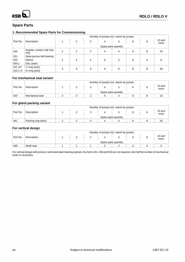
RDLO / RDLO V
54 1387.5/2--10Subject to technical modifications
Spare Parts
1. Recommended Spare Parts for CommissioningNumber of pumps incl. stand--by pumps
Part No. Description 1 2 3 4 5 6 8 10 andmore
Spare parts quantity
320 Angular contact ball bea-ring 2 2 2 4 4 6 8 10
321 Deep groove ball bearing520 Sleeve 1 1 1 2 2 3 4 5550.1 Disc (sets)
1 1 1 2 2 3 4 5
411.1/2 V--ring (sets)1 2 3 4 5 6 8 10
412.1--9 O--ring (sets)1 2 3 4 5 6 8 10
For mechanical seal variantNumber of pumps incl. stand--by pumps
Part No. Description 1 2 3 4 5 6 8 10 andmore
Spare parts quantity433 Mechanical seal 2 2 2 4 4 6 8 10
For gland packing variantNumber of pumps incl. stand--by pumps
Part No. Description 1 2 3 4 5 6 8 10 andmore
Spare parts quantity461 Packing ring (sets) 1 2 3 4 5 6 8 10
For vertical designNumber of pumps incl. stand--by pumps
Part No. Description 1 2 3 4 5 6 8 10 andmore
Spare parts quantity430 Shaft seal 1 1 1 2 2 3 4 5
For vertical design with product--lubricated plain bearing (option), the items 321, 430 and 520 are not required; only half the number of mechanicalseals is necessary.

RDLO / RDLO V
551387.5/2--10 Subject to technical modifications
2. Recommended Spare Parts for 2 Years’ Operation (8000 hours per year)
Number of pumps incl. stand--by pumps
Part No. Description 1 2 3 4 5 6 8 10 andmore
Spare parts quantity211 Shaft, with520 Sleeve920.3/4 Pair of nuts
1 1 1 2 3932 Circlip
-- -- -- 1 1 1 2 3
940.1--4 Key950 Disc spring234 Impeller -- -- -- 1 1 1 2 3
320 Angular contact ball bea-ring 2 2 2 4 4 6 8 10
321 Deep groove ball bearing 1 1 1 2 2 3 4 5550.1 Disc (sets) 1 1 1 2 2 3 4 5411.1/2 V--rings (sets)
1 2 3 4 5 6 8 10412.1--9 O--rings (sets)
1 2 3 4 5 6 8 10
502 Casing wear ring (sets) 1 1 1 2 2 3 4 5503 Impeller wear ring (sets) 1 1 1 2 2 3 4 5
For mechanical seal variantNumber of pumps incl. stand--by pumps
Part No. Description 1 2 3 4 5 6 8 10 andmore
Spare parts quantity433 Mechanical seal 2 2 2 4 4 6 8 10457.2 Neck ring (sets) -- -- -- 2 2 2 4 6
524.2 Shaft protecting sleeve,with 2 2 2 4 4 6 8 10
940.5 Key2 2 2 4 4 6 8 10
For gland packing variantNumber of pumps incl. stand--by pumps
Part No. Description 1 2 3 4 5 6 8 10 andmore
Spare parts quantity452 Gland (2--piece)457.1/3 Neck ring -- -- -- 2 2 2 4 6458 Lantern ring
2 2 2 4 6
461 Packing ring (sets) 4 8 12 16 20 24 32 40524.1 Shaft protecting sleeve 2 2 2 4 4 6 8 10
For vertical designNumber of pumps incl. stand--by pumps
Part No. Description 1 2 3 4 5 6 8 10 andmore
Spare parts quantity430 Shaft seal 1 1 1 2 2 3 4 5
For vertical design with product--lubricated plain bearingNumber of pumps incl. stand--by pumps
Part No. Description 1 2 3 4 5 6 8 10 andmore
Spare parts quantity524.3 Shaft protecting sleeve545 Bearing bush, with 1 1 1 2 2 3 4 5940.6 Key
1 1 1 2 2 3 4 5
For vertical design with product--lubricated plain bearing (option), the items 321, 430 and 520 are not required; only half the number of the items433, 452, 457.1--3, 458, 525.1/2 and 940.5 is required.

RDLO / RDLO V
56 1387.5/2--10Subject to technical modifications
3. Recommended Spare Parts for 5 Years’ Operation (8000 hours per year)
Number of pumps incl. stand--by pumps
Part No. Description 1 2 3 4 5 6 8 10 andmore
Spare parts quantity211 Shaft, with520 Sleeve920.3/4 Pair of nuts
1 1 1 2 2 2 4 6932 Circlip
1 1 1 2 2 2 4 6
940.1--4 Key950 Disc spring234 Impeller 1 1 1 2 2 2 4 6
320 Angular contact ball bea-ring 4 4 4 8 8 12 16 20
321 Deep groove ball bearing2 2 2 4 4 6 8 10
550.1 Disc (sets)2 2 2 4 4 6 8 10
411.1/2 V--ring (sets)2 2 6 8 8 12 16 20
412.1--9 O--ring (sets)2 2 6 8 8 12 16 20
502 Casing wear ring (sets)2 2 2 4 4 6 8 10
503 Impeller wear ring (sets)2 2 2 4 4 6 8 10
for mechanical seal variantNumber of pumps incl. stand--by pumps
Part No. Description 1 2 3 4 5 6 8 10 andmore
Spare parts quantity433 Mechanical seal 4 4 4 8 8 12 16 20457.2 Neck ring 2 2 2 4 4 4 8 12
524.2 Shaft protecting sleeve,with 4 4 4 8 8 12 16 20
940.5 Key4 4 4 8 8 12 16 20
for gland packing variantNumber of pumps incl. stand--by pumps
Part No. Description 1 2 3 4 5 6 8 10 andmore
Spare parts quantity452 Gland (2--piece)457.1/3 Neck ring 2 2 2 4 4 4 8 12458 Lantern ring
2 2 2 4 4 4 8 12
461 Packing ring (sets) 10 20 30 40 50 60 80 100524.1 Shaft protecting sleeve 4 4 4 8 8 12 16 20
for vertical designNumber of pumps incl. stand--by pumps
Part No. Description 1 2 3 4 5 6 8 10 andmore
Spare parts quantity430 Shaft seal 2 2 2 4 4 6 8 10
for vertical design with product--lubricated plain bearingNumber of pumps incl. stand--by pumps
Part No. Description 1 2 3 4 5 6 8 10 andmore
Spare parts quantity524.3 Shaft protecting sleeve545 Bearing bush, with 2 2 2 4 4 6 8 10940.6 Key
2 2 2 4 4 6 8 10
For vertical design with product--lubricated plain bearing (option), the items 321, 430 and 520 are not required; only half the number of the items433, 452, 457.1--3, 458, 524.1/2 and 940.5 is required.

RDLO / RDLO V
571387.5/2--10 Subject to technical modifications
Interchangeability of Pump Components, Horizontal Pump
Description
mp
size
Pum
psh
aft
Ang
ular
cont
act
ball
bear
ing
Dee
pgr
oove
ball
bear
ing
Bea
ring
hous
ing
Bea
ring
cove
r
Sha
ftse
alho
usin
g
Gla
nd
Pac
king
ring
Nec
krin
g
Sle
eve
Spa
cer
slee
ve
Spa
cer
slee
ve
Sha
ftpr
otec
t.sl
eeve
Sha
ftpr
otec
t.sl
eeve
Dis
c
Nut
Dis
csp
ring
Cas
ing
wea
rrin
g
Impe
ller
wea
rrin
g
Pum
p
Part No.
P
211
320
321
350.
1
360
441
452
461
457
520
525.
1
525.
3
524.
1
524.
2
550.
1
920
950
502
503
350--5751 1 1
350--6901 1 1 1 1
1
1 1 1 1 1 1 1 1 1 1 1
1 1
400--7051 1 1 1 1
2
1 1 1 1 1 1 1 1 1 1 1
2 2400--935
2 2 2
400--6652 3 2 3 3
400--5252 3 2 3 3
500--585 2 2 2 2 4 2 2 2 2 2 2 2 2 2 2 4 4500--685
3
2 2 2 2 4 2 2 2 2 2
3
2 2 2 2 2 4 4
600--6003
5
3
5 5600--705
5 5 5
500--8356 6 6
500--8604 3 3 3 3
6
3 3 3 3 3 4 3 3 3 3 3
6 6
500--10154 3 3 3 3
7
3 3 3 3 3 4 3 3 3 3 3
7 7500--1035
7 7 7
600--8855 5 8 8
600--10755
4 4 4 4 8 4 4 4 4 45
4 4 4 4 48 8
700--980 6 6 9 99
Same figure means same component for horizontal and vertical pump
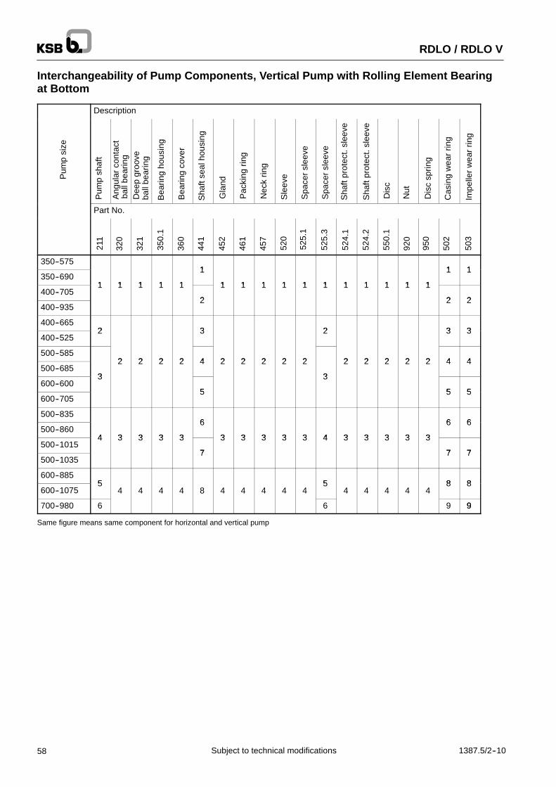
RDLO / RDLO V
58 1387.5/2--10Subject to technical modifications
Interchangeability of Pump Components, Vertical Pump with Rolling Element Bearingat Bottom
Description
Pum
psi
ze
Pum
psh
aft
Ang
ular
cont
act
ball
bear
ing
Dee
pgr
oove
ball
bear
ing
Bea
ring
hous
ing
Bea
ring
cove
r
Sha
ftse
alho
usin
g
Gla
nd
Pac
king
ring
Nec
krin
g
Sle
eve
Spa
cer
slee
ve
Spa
cer
slee
ve
Sha
ftpr
otec
t.sl
eeve
Sha
ftpr
otec
t.sl
eeve
Dis
c
Nut
Dis
csp
ring
Cas
ing
wea
rrin
g
Impe
ller
wea
rrin
g
Part No.
211
320
321
350.
1
360
441
452
461
457
520
525.
1
525.
3
524.
1
524.
2
550.
1
920
950
502
503
350--5751 1 1
350--6901 1 1 1 1
1
1 1 1 1 1 1 1 1 1 1 1
1 1
400--7051 1 1 1 1
2
1 1 1 1 1 1 1 1 1 1 1
2 2400--935
2 2 2
400--6652 3 2 3 3
400--5252 3 2 3 3
500--5852 2 2 2 4 2 2 2 2 2 2 2 2 2 2 4 4
500--6853
2 2 2 2 4 2 2 2 2 2
3
2 2 2 2 2 4 4
600--6003
5
3
5 5600--705
5 5 5
500--8356 6 6
500--8604 3 3 3 3
6
3 3 3 3 3 4 3 3 3 3 3
6 6
500--10154 3 3 3 3
7
3 3 3 3 3 4 3 3 3 3 3
7 7500--1035
7 7 7
600--8855 5 8 8
600--10755
4 4 4 4 8 4 4 4 4 45
4 4 4 4 48 8
700--980 6 6 9 99
Same figure means same component for horizontal and vertical pump

RDLO / RDLO V
591387.5/2--10 Subject to technical modifications
Interchangeability of Pump Components, Vertical Pump with Plain Bearing at Bottom
Description
psi
ze
Pum
psh
aft
Ang
ular
cont
act
ball
bear
ing
Cov
er
Bea
ring
hous
ing
Bea
ring
cove
r
Sha
ftse
alho
usin
g
Gla
nd
Pac
king
ring
Nec
krin
g
Spa
cer
slee
ve
Spa
cer
slee
ve
Spa
cer
slee
ve
Sha
ftpr
otec
t.sl
eeve
Sha
ftpr
otec
t.sl
eeve
Sha
ftpr
otec
t.sl
eeve
Bea
ring
bush
Dis
c
Dis
c
Nut
Dis
csp
ring
Cas
ing
wea
rrin
g
Impe
ller
wea
rrin
g
Pum
p
Part No.
P
211
320
160
350.
1
360
441
452
461
457
525.
1
525.
2
525.
3
524.
1
524.
2
524.
3
545
550.
1
550.
3
920.
1
950
502
503
350--5751 1 1
350--69011 1 11 1 1
1
1 1 1 1 11 1 1 1 11 11 1 11 1 1
1 1
400--70511 1 11 1 1
2
1 1 1 1 11 1 1 1 11 11 1 11 1 1
2 2400--935
2 2 2
400--66521 3 21 2 3 3
400--52521 3 21 2 3 3
500--5852 21 2 2 4 2 2 2 2 2 2 21 21 2 21 2 2 4 4
500--68531
2 21 2 2 4 2 2 2 2
31 3
2 2 21 21 2 21 2 2 4 4
600--60031
5
31 3
5 5600--705
5 5 5
500--8356 6 6
500--86041 3 31 3 3
6
3 3 3 3 41 4 3 3 31 31 3 31 3 3
6 6
500--101541 3 31 3 3
7
3 3 3 3 41 4 3 3 31 31 3 31 3 3
7 7500--1035
7 7 7
600--88551 51 5 8 8
600--107551
4 41 4 4 8 4 4 4 451 5
4 4 41 41 4 41 4 48 8
700--980 61 61 6 9 9
Same figure means same component for horizontal and vertical pump

Sub
ject
tote
chni
calm
odifi
catio
ns13
87.5
/2--1
026
.11.
2004
XB
S
KSB Aktiengesellschaft
Johann--Klein--Str. 9 � 67227 Frankenthal � Germany
Phone: +49 6233 86--2656 � Fax: +49 6233 86--3412 � E--mail: [email protected] � www.ksb.com
RDLO / RDLO V