You- Chiun Wang, Member, IEEE, Yao-Yu Hsieh, and Yu- Chee Tseng, Senior Member, IEEE

Illumination Normalization withTime-Dependent Intrinsic Images
for Video SurveillanceYasuyuki Matsushita, Member, IEEE, Ko Nishino, Member, IEEE,
Katsushi Ikeuchi, Fellow, IEEE, and Masao Sakauchi, Member, IEEE
Abstract—Variation in illumination conditions caused by weather, time of day, etc., makes the task difficult when building video
surveillance systems of real world scenes. Especially, cast shadows produce troublesome effects, typically for object tracking from a
fixed viewpoint, since it yields appearance variations of objects depending on whether they are inside or outside the shadow. In this
paper, we handle such appearance variations by removing shadows in the image sequence. This can be considered as a
preprocessing stage which leads to robust video surveillance. To achieve this, we propose a framework based on the idea of intrinsic
images. Unlike previous methods of deriving intrinsic images, we derive time-varying reflectance images and corresponding
illumination images from a sequence of images instead of assuming a single reflectance image. Using obtained illumination images,
we normalize the input image sequence in terms of incident lighting distribution to eliminate shadowing effects. We also propose an
illumination normalization scheme which can potentially run in real time, utilizing the illumination eigenspace, which captures the
illumination variation due to weather, time of day, etc., and a shadow interpolation method based on shadow hulls. This paper
describes the theory of the framework with simulation results and shows its effectiveness with object tracking results on real scene
data sets.
Index Terms—Intrinsic images, reflectance, shadow removal, illumination normarization, video surveillance, robust tracking.
�
1 INTRODUCTION
VIDEO surveillance systems involving object detectionand tracking require robustness against illumination
changes caused by variation of, for instance, weatherconditions. Difficult situations arise not only by the changeof illumination conditions, but also by the large castshadows of surrounding structures, i.e., large buildingsand trees. Since most visual tracking algorithms rely on theappearance of the target object, typically using color,texture, and feature points as cues, these shadows degradethe quality of tracking. In urban scenes, where buildingrobust traffic monitoring systems is of special interest, it isusual to have large shadows cast by tall buildingssurrounding the road, e.g., Fig. 2a. Building a robust videosurveillance system under such an environment is achallenging task. To make the system insensitive todramatic change of illumination conditions and robustagainst large static cast shadows, it would be valuable tocancel out those illumination effects from the image
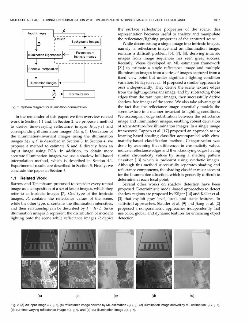
sequence. Our goal is to “normalize” the input imagesequence in terms of the distribution of incident lighting toremove illumination effects including shadow effects. Weshould note that our method does not consider shadowscast by moving objects but those cast by static objects suchas buildings and trees. To achieve this goal, we propose anapproach based on intrinsic images. Our method is com-posed of two parts as shown in Fig. 1.
The first part is the estimation of intrinsic images, which
is an offline process, depicted in A of Fig. 1. In this part,
first, the scene background image sequence is estimated to
remove moving objects from the input image sequence.
Using this background image sequence, we then derive
intrinsic images using our estimation method which is
extended from Weiss’s ML estimation method [21]. Using
the estimated illumination image, which is a part of intrinsic
images, we are able to robustly cancel out the illumination
effects from input images of the same scene, enabling many
vision algorithms such as tracking to run robustly. After the
derivation, we construct a database using Principal Com-
ponent Analysis (PCA), which we refer to as illumination
eigenspace. This linear subspace captures the variation of
lighting conditions in the illumination images. The sub-
space is used for the following direct estimation method.The second part is a direct estimation of illumination
images, shown in B of Fig. 1. Using the preconstructed
illumination eigenspace, we estimate an illumination image
directly from an input image. To obtain accurate illumina-
tion images, shadow interpolation using shadow hulls is
accomplished.
1336 IEEE TRANSACTIONS ON PATTERN ANALYSIS AND MACHINE INTELLIGENCE, VOL. 26, NO. 10, OCTOBER 2004
. Y. Matsushita is with Microsoft Research Asia, 3/F, Beijing Sigma Center,No. 49, Zhichun Road, Hai Dian District, Beijing, China 100080.E-mail: [email protected].
. K. Nishino is with the Department of Computer Science, ColumbiaUniversity, 1214 Amsterdam Avenue, MC 0401 New York, NY 10027.E-mail: [email protected].
. K. Ikeuchi and M. Sakauchi are with the Institute of Industrial Science, theUniversity of Tokyo, 4-6-1 Komaba, Meguro-ku, Tokyo 153-8505, Japan.E-mail: [email protected], [email protected].
Manuscript received 1 July 2003; revised 22 Mar. 2004; accepted 1 Apr. 2004.Recommended for acceptance by R. Basri.For information on obtaining reprints of this article, please send e-mail to:[email protected], and reference IEEECS Log Number TPAMI-0151-0703.
0162-8828/04/$20.00 � 2004 IEEE Published by the IEEE Computer Society
In the remainder of this paper, we first overview related
work in Section 1.1 and, in Section 2, we propose a method
to derive time-varying reflectance images Rðx; y; tÞ and
corresponding illumination images Lðx; y; tÞ. Derivation of
the illumination-invariant images using the illumination
images Lðx; y; tÞ is described in Section 3. In Section 4, we
propose a method to estimate R and L directly from an
input image using PCA. In addition, to obtain more
accurate illumination images, we use a shadow hull-based
interpolation method, which is described in Section 4.1.
Experimental results are described in Section 5. Finally, we
conclude the paper in Section 6.
1.1 Related Work
Barrow and Tenenbaum proposed to consider every retinal
image as a composition of a set of latent images, which they
refer to as intrinsic images [7]. One type of the intrinsic
images, R, contains the reflectance values of the scene,
while the other type, L, contains the illumination intensities,
and their relationship can be described by I ¼ R � L. Sinceillumination images L represent the distribution of incident
lighting onto the scene while reflectance images R depict
the surface reflectance properties of the scene, thisrepresentation becomes useful to analyze and manipulatethe reflectance/lighting properties of the captured scene.
While decomposing a single image into intrinsic images,namely, a reflectance image and an illumination image,remains a difficult problem [5], [7], [4], deriving intrinsicimages from image sequences has seen great success.Recently, Weiss developed an ML estimation framework[21] to estimate a single reflectance image and multipleillumination images from a series of images captured from afixed view point but under significant lighting conditionvariation. Finlayson et al. [6] proposed a similar approach toours independently. They derive the scene texture edgesfrom the lighting-invariant image, and by subtracting thoseedges from the raw input images, they successfully deriveshadow-free images of the scene. We also take advantage ofthe fact that the reflectance image essentially models thescene texture in a manner invariant to lighting conditions.We accomplish edge substitution between the reflectanceimage and illumination images, enabling robust derivationof scene-texture-free illumination images. In a single imageframework, Tappen et al. [17] proposed an approach to uselearning-based shading classifier accompanied with chro-maticity-based classification method. Categorization wasdone by assuming that differences in chromaticity valuesindicate reflectance edges and then classifying edges havingsimilar chromaticity values by using a shading patternclassifier [13] which is prelearnt using synthetic images.Although this method successfully separates shading andreflectance components, the shading classifier must accountfor the illumination direction, which is generally difficult todetermine at each local point.
Several other works on shadow detection have beenproposed. Deterministic model-based approaches to detectshadow regions are proposed by Kilger [14] and Koller et al.[3] that exploit gray level, local, and static features. Instatistical approaches, Stauder et al. [9] and Jiang et al. [2]proposed a nonparametric approaches independently thatuse color, global, and dynamic features for enhancing objectdetection.
MATSUSHITA ET AL.: ILLUMINATION NORMALIZATION WITH TIME-DEPENDENT INTRINSIC IMAGES FOR VIDEO SURVEILLANCE 1337
Fig. 1. System diagram for illumination-normalization.
Fig. 2. (a) An input image iðx; y; tÞ, (b) reflectance image derived by ML estimation rwðx; yÞ, (c) illumination image derived by ML estimation lwðx; y; tÞ,(d) our time-varying reflectance image rðx; y; tÞ, and (e) our illumination image lðx; y; tÞ.

2 INTRINSIC IMAGE ESTIMATION
Our work is inspired by ML estimation method [21] ofestimating intrinsic images from a sequence of imagescaptured from a fixed viewpoint under varying illumina-tion. In this method, natural image statistics [8] are used aspriors to estimate a single reflectance image and multipleillumination images. Although the method assumes thescene to be Lambertian, it is still effective to extract thescene texture, not a reflectance image, from a scene whichcontains specular surfaces. In that case, however, theestimated reflectance image does not accurately depictsurface reflectance property of the scene and some portionof the reflectance property will be included in illuminationimages. If we consider real world scenes, it is often difficultto expect the Lambertian assumption to hold. A typicalexample is white lines on a road surface, which showvariable reflection with respect to illumination changes. Weprepared a synthetic scene shown in Fig. 2a. The scene iscomposed of a road surface and pedestrian stripes that havedifferent reflectance property from the road surface. Withan assumption that the view point is fixed and the scene isroughly Lambertian, the ML estimation-based methodderives the scene reflectance image by taking the medianof filtered input image in log domain. Denoting logreflectance of the road surface and stripes with r1 and r2,respectively, the reflectance difference at the boundary ofthe road surface and the stripes becomes jr1 � r2j. Since theML estimation method assumes that the scene is Lamber-tian, i.e., r1 and r2 are constants, the difference jr1 � r2j isalso constant. However, if the Lambertian assumption doesnot hold, e.g., r2 is varying, jr1 � r2j is no longer constant. Inthat case, the error fjr1 � r2ðtÞj �mediantjr1 � r2ðtÞjg ap-pears in illumination images as a ghost of scene texture asshown in Fig. 2c.
To handle this problem, we propose to assume a set of
time-varying reflectance images Rðx; y; tÞ instead of a time-
invariant reflectance image Rðx; yÞ. To derive the time-
varying reflectance images, we start with estimating a scene
texture image using the ML estimation method [21]. We
denote the scene texture image which is the reflectance
image estimated by the ML estimation method and the
illumination image with subscript w, i.e., Rw and Lw, and
our reflectance image and illumination image, R and L,
respectively. Applying the ML estimation method, a single
reflectance image Rwðx; yÞ and a set of illumination images
Lwðx; y; tÞ are estimated. Our goal is to derive time-varying,
i.e., lighting condition dependent, reflectance images
Rðx; y; tÞ, and corresponding illumination images Lðx; y; tÞthat do not contain scene texture.
Iðx; y; tÞ ¼ Rðx; y; tÞ � Lðx; y; tÞ ð1Þ
We use lower-case letters to denote variables in log domain,e.g., r represents the logarithm of R. With nth derivativefilters fn, a filtered reflectance image rwn is computed bytaking median along the time axis of fn ? iðx; y; tÞ, where ?
represents convolution. We used two derivative filters, i.e.,f0 ¼ ½0 1 � 1� and f1 ¼ ½0 1 � 1�T . With those filters, inputimages are decomposed into intrinsic images by Weiss’s
method as described in (2). The method is based on thestatistics of natural images [8].
r̂rwnðx; yÞ ¼ mediantffn ? iðx; y; tÞg: ð2Þ
The filtered illumination images lwnðx; y; tÞ are then com-puted by using estimated filtered reflectance image rwn.
l̂lwnðx; y; tÞ ¼ fn ? iðx; y; tÞ � r̂rwnðx; yÞ: ð3Þ
To be precise, l is computed by l ¼ i� r in the unfiltereddomain in Weiss’s original work while we estimate lin the derivative domain for the following edge-basedmanipulation.
We use the output of the ML estimation method as initialvalues of our intrinsic image estimation. As mentionedabove, the goal of our method is to derive time-dependentreflectance images Rðx; y; tÞ and their corresponding illu-mination images Lðx; y; tÞ. The basic idea of the method is toestimate time-varying reflectance components by cancellingthe scene texture from initial illumination images. To factorout the scene textures from the illumination images andassociate them with reflectance images, we use the textureedges of rw. We take a straightforward approach to removetexture edges from lw and derive illumination imageslðx; y; tÞ with (4) and (5). These equations describe that ifthe magnitude of a pixel in the gradient of the textureimage, i.e., jrwnðx; yÞj, is larger than a threshold T , then thisis an evidence of a texture edge. In that case, the textureedges that appear in the gradient of the illumination imageare removed from the illumination image, and the removededge is added to the time-varying reflectance image. Here,we assume that there is no scene texture edge which has notappeared in rwn. Since the scene texture edges are the edgeswhich stay at the same position, it is reasonable to assumethat they are captured in rwn.
lnðx; y; tÞ ¼0 if jrwnðx; yÞj > Tlwnðx; y; tÞ otherwise;
�ð4Þ
rnðx; y; tÞ ¼rwnðx; yÞ þ lwnðx; y; tÞ if jrwnj > Trwnðx; yÞ otherwise;
�ð5Þ
where T represents a threshold value. While we currentlymanually set the threshold value T used to detect textureedges in rwn, we found the procedure is not so sensitive tothe threshold as long as it covers texture edges well.
Since the operation is linear, the following equation isimmediately confirmed.
fn ? iðx; y; tÞ ¼ rwnðx; yÞ þ lwnðx; y; tÞ¼ rnðx; y; tÞ þ lnðx; y; tÞ:
ð6Þ
Finally, time-varying reflectance images rðx; y; tÞ and scenetexture-free illumination images lðx; y; tÞ are recovered fromfiltered reflectance rn and illumination images ln throughthe following deconvolution process as done in [21].
ðr̂r; l̂lÞ ¼ g ?Xn
frn ? ðr̂rn; l̂lnÞ !
; ð7Þ
where frn is the reversed filter of fn, and g is the filter whichsatisfies the following equation:
1338 IEEE TRANSACTIONS ON PATTERN ANALYSIS AND MACHINE INTELLIGENCE, VOL. 26, NO. 10, OCTOBER 2004

g ?Xn
frn ? fn
!¼ �: ð8Þ
Reconstruction of images from edges has been studiedfor a long time. The problem can be formulated as aboundary value problem, and an alternative technique thathas been widely accepted is the multigrid method. Multi-grid methods solve the boundary value problem efficientlyby changing the problem into a set of linear algebraicequations. Multigrid methods can be used to reconstructimages from edges as an alternative to the methoddescribed above. Readers are referred to a good overviewon multigrid solvers by Press et al. [20].
To demonstrate the effectiveness of our method forderiving time-dependent intrinsic images, we rendered aCG scene which contains cast shadows and surface patcheswith different reflectance properties, which is analogous toreal road surfaces, e.g., pedestrian stripes. Fig. 2 shows aside-by-side comparison of the results of applying the MLestimation method and our method. The first row is the CGscene, where the scene has the property that the histogramof derivative-filtered output is sparse, which is the requiredproperty of the ML estimation-based decomposition meth-od and also is the statistics usually found in natural images.As can be seen clearly, texture edges are successfullyremoved from our illumination image while they obviouslyremain in illumination image derived by the ML estimationmethod. Considering an illumination image to be an imagewhich represents the distribution of incident lighting, ourillumination image is much better since incident lighting hasnothing to do with the scene reflectance properties.
3 SHADOW REMOVAL
Using the obtained scene illumination images by ourmethod, the input image sequence can be normalized interms of illumination.
To estimate the intrinsic images of the scene wherevideo surveillance systems are to be applied, it is necessaryto remove moving objects from the input image sequencebecause our method requires the scene to be static.Therefore, we first create background images in each shorttime range (�T ) in the input image sequence, assumingthat the illumination does not vary in that short timeperiod. We simply use the median image of the short inputsequence as the background image, but of course the morecomplicated methods would give the better backgroundimages [11]. The assumption here is that moving objects inthe scene are not observed at the same point longer thanthe background in �T . These background images Bðx; y; tÞare used for the estimation of intrinsic images. Using theestimation method described in the former section, eachimage in the background image sequence is decomposedinto corresponding reflectance images Rðx; y; tÞ and illu-mination images Lðx; y; tÞ.
Bðx; y; tÞ ¼ Rðx; y; tÞ � Lðx; y; tÞ: ð9Þ
Once decomposed into intrinsic images, any image whoseillumination condition is captured in the series of Bðx; y; tÞcan be normalized with regards to its illumination conditionby simply dividing the input image Iðx; y; tÞ by its
corresponding estimated illumination image Lðx; y; tÞ.Through the normalization, cast shadows are also removed
from the input images.Since the incident lighting effects are fully captured in
illumination images Lðx; y; tÞ, the normalization by dividing
with L corresponds to removing the incident lighting
distribution from the input image sequence. Let us denote
the resulting illuminance-invariant image with Nðx; y; tÞ,that can be derived by the following equation:
Nðx; y; tÞ ¼ Iðx; y; tÞ=Lðx; y; tÞ: ð10Þ
Fig. 3 shows the result of our normalization method.
Fig. 3a shows the input image I and Fig. 3b represents the
illuminance-invariant image N . Note shadows of the
buildings are removed in N .Since we consider the time-dependent reflectance
values, accurate normalization of incident lighting can be
done compared to using illumination images that are
derived by ML estimation method. Fig. 4 depicts the
difference between using our illumination image L
(Figs. 4a and 4c) and using illumination image Lw by
ML estimation (Figs. 4b and 4d). As can be seen in the
images, the pedestrian stripes appear over the trucks in
every right-hand side image. On the other hand, when
using our illumination images, the ghost of pedestrian
stripes is almost vanished as seen in every left-hand side
image. This is because our method handles reflectance
MATSUSHITA ET AL.: ILLUMINATION NORMALIZATION WITH TIME-DEPENDENT INTRINSIC IMAGES FOR VIDEO SURVEILLANCE 1339
Fig. 3. An input image I (a) and the illuminance-invariant image N (b).
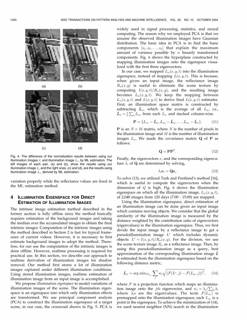
variation properly while the reflectance values are fixed inthe ML estimation method.
4 ILLUMINATION EIGENSPACE FOR DIRECT
ESTIMATION OF ILLUMINATION IMAGES
The intrinsic image estimation method described in theformer section is fully offline since the method basicallyrequires estimation of the background images and takingthe median over the accumulated images to obtain the finalintrinsic images. Computation of the intrinsic images usingthe method described in Section 2 is fast for typical frame-sizes of current videos. However, it is necessary to firstestimate background images to adopt the method. There-fore, for our use the computation of the intrinsic images isdone offline. However, realtime processing is required forpractical use. In this section, we describe our approach torealtime derivation of illumination images for shadowremoval. Our method first stores a lot of illuminationimages captured under different illumination conditions.Using stored illumination images, realtime estimation ofillumination image from an input image is accomplished.
We propose illumination eigenspace to model variations ofillumination images of the scene. The illumination eigen-space is an eigenspace into which only illumination effectsare transformed. We use principal component analysis(PCA) to construct the illumination eigenspace of a targetscene, in our case, the crossroad shown in Fig. 5. PCA is
widely used in signal processing, statistics, and neuralcomputing. The reason why we employed PCA is that weassume the observed illumination images have Gaussiandistribution. The basic idea in PCA is to find the basiccomponents ½s1; s2; . . . ; sn� that explain the maximumamount of variance possible by n linearly transformedcomponents. Fig. 6 shows the hyperplane constructed bymapping illumination images onto the eigenspace visua-lized with the first three eigenvectors.
In our case, we mapped Lwðx; y; tÞ into the illuminationeigenspace, instead of mapping Lðx; y; tÞ. This is because,when given an input image, the reflectance imageRwðx; yÞ is useful to eliminate the scene texture bycomputing Iðx; y; tÞ=Rwðx; yÞ, and the resulting imagebecomes Lwðx; y; tÞ. We keep the mapping betweenLwðx; y; tÞ and Lðx; y; tÞ to derive final Lðx; y; tÞ estimates.First, an illumination space matrix is constructed bysubtracting �LLw, which is the average of all Lw, i.e.,�LLw ¼ 1
n
Pn Lw, from each Lw and stacked column-wise.
P ¼ fLw1� �LLw; Lw2
� �LLw; . . . ; Lwn� �LLwg: ð11Þ
P is an N �M matrix, where N is the number of pixels inthe illumination image and M is the number of illuminationimages Lw. We made the covariance matrix Q of P asfollows:
Q ¼ PPT : ð12Þ
Finally, the eigenvectors ei and the corresponding eigenva-lues �i of Q are determined by solving,
�iei ¼ Qei: ð13Þ
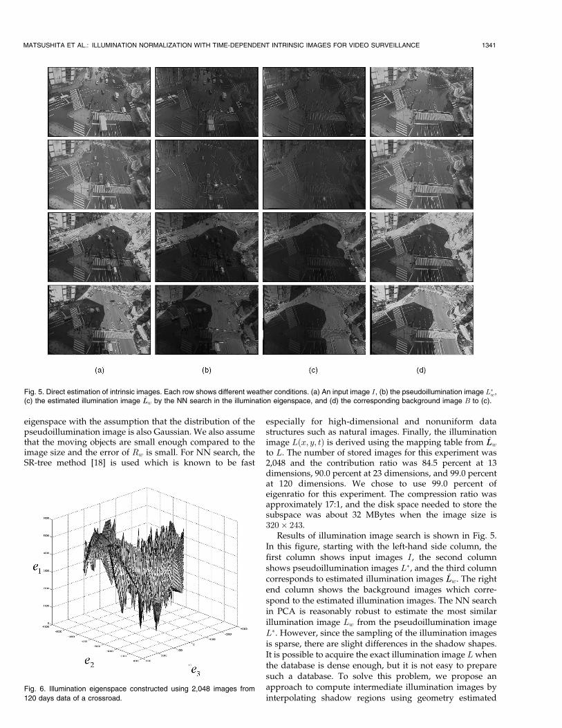
To solve (13), we utilized Turk and Pentland’s method [16],which is useful to compute the eigenvectors when thedimension of Q is high. Fig. 6 shows the illuminationeigenspace on which all the illumination image, Lwðx; y; tÞ,of 2,048 images from 120 days (7:00 - 15:00) are mapped.
Using the illumination eigenspace, direct estimation ofan illumination image can be done given an input imagewhich contains moving objects. We consider that the globalsimilarity of the illumination image is measured by thedistance weighted by the contribution ratio of eigenvectors(eigenvalues) in the illumination eigenspace. Thus, we firstdivide the input image by a reflectance image to get apseudoillumination image L� which includes dynamicobjects: L� ¼ Iðx; y; tÞ=Rwðx; yÞ. For the division, we usethe scene texture image Rw as a reflectance image. Then, byusing this pseudoillumination image as a query, bestapproximation of the corresponding illumination image L̂Lis estimated from the illumination eigenspace based on thefollowing distance metric,
L̂Lw ¼ arg min8Lwi
Xj
wj
ffiffiffiffiffiffiffiffiffiffiffiffiffiffiffiffiffiffiffiffiffiffiffiffiffiffiffiffiffiffiffiffiffiffiffiffiffiffiffiffiffiffiffiffiffiffiffiffiffiFðL�; jÞ � FðLwi
; jÞð Þ2;q
ð14Þ
where F is a projection function which maps an illumina-tion image onto the jth eigenvector, and wj ¼ �j=
P� �i
where �is are the eigenvalues. The term FðLwiÞ is
premapped onto the illumination eigenspace, each Lwiis a
point in the eigenspace. To achieve the minimization of (14),we used nearest neighbor (NN) search in the illumination
1340 IEEE TRANSACTIONS ON PATTERN ANALYSIS AND MACHINE INTELLIGENCE, VOL. 26, NO. 10, OCTOBER 2004
Fig. 4. The difference of the normalization results between using ourillumination images L and illumination image Lw by ML estimation. Theleft images of each pair, (a) and (b), show the results using ourillumination image L, and the right ones, (c) and (d), are the results usingillumination image Lw derived by ML estimation.
eigenspace with the assumption that the distribution of thepseudoillumination image is also Gaussian. We also assumethat the moving objects are small enough compared to theimage size and the error of Rw is small. For NN search, theSR-tree method [18] is used which is known to be fast
especially for high-dimensional and nonuniform datastructures such as natural images. Finally, the illuminationimage Lðx; y; tÞ is derived using the mapping table from L̂Lw
to L. The number of stored images for this experiment was2,048 and the contribution ratio was 84.5 percent at 13dimensions, 90.0 percent at 23 dimensions, and 99.0 percentat 120 dimensions. We chose to use 99.0 percent ofeigenratio for this experiment. The compression ratio wasapproximately 17:1, and the disk space needed to store thesubspace was about 32 MBytes when the image size is320� 243.
Results of illumination image search is shown in Fig. 5.In this figure, starting with the left-hand side column, thefirst column shows input images I, the second columnshows pseudoillumination images L�, and the third columncorresponds to estimated illumination images L̂Lw. The rightend column shows the background images which corre-spond to the estimated illumination images. The NN searchin PCA is reasonably robust to estimate the most similarillumination image Lw from the pseudoillumination imageL�. However, since the sampling of the illumination imagesis sparse, there are slight differences in the shadow shapes.It is possible to acquire the exact illumination image Lwhenthe database is dense enough, but it is not easy to preparesuch a database. To solve this problem, we propose anapproach to compute intermediate illumination images byinterpolating shadow regions using geometry estimated
MATSUSHITA ET AL.: ILLUMINATION NORMALIZATION WITH TIME-DEPENDENT INTRINSIC IMAGES FOR VIDEO SURVEILLANCE 1341
Fig. 5. Direct estimation of intrinsic images. Each row shows different weather conditions. (a) An input image I, (b) the pseudoillumination image L�w,
(c) the estimated illumination image L̂Lw by the NN search in the illumination eigenspace, and (d) the corresponding background image B to (c).
Fig. 6. Illumination eigenspace constructed using 2,048 images from
120 days data of a crossroad.

from sampled cast shadow regions and sunlight angles. Thedetails are described in Section 4.1.
As for the computational cost, the average time of theNN search is shown in Table 1 with MIPS R12000 300MHz,when the number of stored illumination images is 2,048, theimage size is 360� 243 and the number of output searchresults is 5. Since the input image is obtained at the intervalof 33ms (at 30 frames/sec), the estimation time is fastenough for realtime processing.
4.1 Shadow Interpolation Using Shadow Hulls
Unfortunately, it is difficult to store all illumination imagesunder every possible illumination condition. NN search inthe illumination eigenspace gives good results, however, itis often the case that they are slightly different from the trueillumination image due to the limitation of the number ofstored illumination images. Therefore, we propose tointerpolate NN search results to generate the final estimateof the illumination image. We assume global intensitychanges are linear as long as they are densely sampled, butthe motion of cast shadows cannot be represented by linearintensity interpolation. To achieve the interpolation of theshadow motion, we propose to use Shadow Hull s. The ideaof shadow hull is the same as Visual Hull (VH) except usingcast shadow silhouette instead of object’s silhouette andillumination source as a view point in VH. VH, also knownas Shape-From-Silhouette (SFS) [15], [1], is a popular3D reconstruction method which estimates the shape ofthe object from multiple silhouette images. These traditionalapproaches basically assume that the object is static.Recently, extending the traditional SFS formulation tohandle the shape of a rigidly moving object over time anda dynamic articulated object are well investigated [12], [10].
Our purpose is to reconstruct the rough shape of anobject (such as a building) which gives enough informationto compute the cast shadow regions given illuminationdirections. Even though parts of many objects cannot berepresented by an SFS-based technique, such as concavities,it does not matter for our method because our purpose isnot reconstructing the 3D scene geometry but generatingintermediate shadow regions. To accomplish shadow hullreconstruction, we use estimated shadow region maps S,sunlight angles which are immediately computed from thetime-stamp, and calibration parameters. Assuming that thescene is roughly planar, we pitch the shadow volume usingthe shadow map S and illumination direction in the worldcoordinate system. Taking the intersection of differentshadow volumes pitched using different shadow maps,the shadow hull can be estimated. The resulting hull is notnecessarily precise, but it gives enough scene geometry tocompute cast shadow region between sampled illumination
conditions. Also, we do not expect this method to work wellif the sampling of the illumination variation is notsufficiently dense.
To compute the intermediate illumination images, wefirst compute the shadow region map S for each storedillumination image. Since an illumination image depicts theintensity distribution of reflected lighting from the scene,we can assume that low intensity pixels in the illuminationimage represent shadowed area. By thresholding, shadowregions S are derived from the illumination images. Toautomatically determine the threshold for shadowed areadetermination, we adopt the clustering technique of Otsu[19]. The threshold is computed from maximizing thebetween-class scatter by minimizing within-class variances.In our case, we classify pixels into two classes, shadowedand lit, assuming shaded pixels can be categorized intoeither of them. We first create an intensity histogram foreach illumination image to obtain the probability densityfunction pðiÞwhere i indicates an intensity value. Assumingthat shadowed pixels have relatively lower intensity than litpixels, we define the cumulative probability functions P forshadowed (Ps) and lit (Pl) area using a threshold value T .
PsðT Þ ¼XTi¼imin
pðiÞ; PlðT Þ ¼Ximax
i¼T
pðiÞ: ð15Þ
In the same manner, we define the mean of the shadowed(�s) and lit (�l) area as functions of the threshold T asfollows:
�sðT Þ ¼XTi¼imin
ipðiÞ; �lðT Þ ¼Ximax
i¼T
ipðiÞ: ð16Þ
Finally, the optimum threshold value Topt can be obtainedby the following equation:
Topt ¼ argmax8T
fPsðT ÞPlðT Þð�sðT Þ � �lðT ÞÞ2g: ð17Þ
Using Topt, we compute shadowed area for eachillumination image and store the shadowed area in shadowmap S. The shadow map S is a Boolean map which stores 1if the pixel is shadowed, otherwise 0.
Shadow regions are then mapped onto the worldcoordinate, and shadow volumes are computed usingshadow regions associated with sunlight angles. By takingthe intersection of shadow volumes in the 3D space, we getthe rough geometry of objects casting shadows, which hasenough information for computing intermediate castshadows (Fig. 7a). Fig. 7b shows the results of shadowinterpolation in a CG scene using an estimated shadow hull.The dark regions show the interpolated shadow regions,while the lighter regions represent the sampled shadowregions.
Shadow interpolation using shadow hulls is useful toestimate the intermediate shadow shapes between sampledlighting conditions. Fig. 8 shows the interpolated result ofthe real world scene. The left-hand column represents theestimated shadow regions, while the right-hand columnshows the corresponding illumination images. The top andbottom row represent the images under sampled illumina-tion conditions, and the middle row depicts the interpolated
1342 IEEE TRANSACTIONS ON PATTERN ANALYSIS AND MACHINE INTELLIGENCE, VOL. 26, NO. 10, OCTOBER 2004
TABLE 1Dimension of the Illumination Eigenspace, Contribution Ratio,
and NN Search Cost

result. With the assumption that illumination angle ismonotonously changing, intermediate shadow regions canbe approximately computed using a shadow hull pitchedby only two neighboring shadow map samples.
For computational efficiency, we adopt a multiple planar
slice representation of shadow hull as shown in Fig. 9. For
each z along the vertical axis, slices parallel to the x-y plane
are assumed. Cast shadows on the world plane are then
projected onto these slices using the illumination direction
to obtain the region where a shadow volume penetrates
each slice. Finally, the intersections of the projected shadow
regions are taken as a shadow hull region on the slice. These
intersections can be computed with simple Boolean opera-
tions. The reason why a set of 2D representation is adopted
instead of 3D representation is that our objective is to
generate intermediate shadow regions and, for that pur-
pose, dense recovery of the shadow hull is not required. The
sampling rate along the z-axis is currently manually set,
however, we have confirmed that as long as it is not too
sparse virtually the same result is obtained. As described
above, intermediate shadow shapes can be computed with
some projection and intersections computations that are
very efficient.Once we obtain the intermediate shadow map Sintðx; yÞ,
we can compute the intermediate illumination image Lint
by interpolating the first k illumination images Lk that are
computed by NN search. With the kth illumination imageobtained by NN search Lk and wk which is the weightingfactor, the distance from L�
w to Lwk(See Section 4) in the
illumination eigenspace, the intermediate illuminationimage Lint can be computed as follows:
MATSUSHITA ET AL.: ILLUMINATION NORMALIZATION WITH TIME-DEPENDENT INTRINSIC IMAGES FOR VIDEO SURVEILLANCE 1343
Fig. 7. Interpolation of cast shadow using a shadow hull. (a) Computing
shadow hulls using shadow regions associated with sunlight angles.
(b) Result of shadow interpolation.
Fig. 8. Shadow hull-based shadow interpolation. Figures in the top andbottom rows are shadow regions and sampled illumination images. Themiddle row shows the interpolated shadow region. Note that theinterpolated result describes only the area of the shadow and is usedto compute the intermediate illumination image. The grid is overlaid forbetter visualization.
Fig. 9. Illustration of shadow hull construction. To efficiently represent
the shadow hull, a set of 2D slices of the shadow hull along the vertical
axis is used instead of a volumetric representation.

Lintðx; yÞ ¼ Sintðx; yÞP
k wkSkðx; yÞLkðx; yÞPk wkSkðx; yÞ
þ ð1� Sintðx; yÞÞP
k wkð1� Skðx; yÞÞLkðx; yÞPk wkð1� Skðx; yÞÞ
;
ð18Þ
whereSkðx; yÞ is amapwhich holds 1 if the pixel ðx; yÞ inLk isinside theshadowregion,otherwise0.Asshownin(18),pixelsin shadow and pixels outside the shadow are separatelyinterpolated. Practically, sometimes it is possible to observe
thatP
k wkð1� Skðx; yÞÞ ¼ 10 orP
k wkðSkðx; yÞÞ¼ 0. In thatcase, the term whose denominator equals zero is treated aszero because the term does not contain any information.
The resulting intermediate illumination image is shown
in middle right in Fig. 8. Fig. 10 shows the comparisonbetween the result of our method and the ground truth. Wecan notice the slight difference between them from Fig. 10c;however, it shows a globally correct shadow shape which is
useful to remove shadow effects from the input image.To evaluate the effectiveness of our shadow interpolation
method, we compared the results with simple imageinterpolation as shown in Fig. 11. Both our result and imageinterpolation result are computed from two neighboring
illumination images. As we can clearly see in the figure, ourmethod generates quite similar cast shadow shape to the
ground truth while the simple interpolation yields a bigghost at the shadow transition area. To quantify thedifference from the ground truth, we evaluated the absoluteintensity difference per pixel. Table 2 shows the average ofthe absolute difference in 12 sets of interpolation results. Inour shadow interpolation method, the error is much smallercompared to image interpolation.
5 EXPERIMENTAL RESULTS
We evaluated our shadow elimination method by objecttracking based on block matching using two differentmatching functions. One is using sum of squared differ-ences (SSD) as a matching function, and the other is usingnormalized correlation function (NCF) instead of SSD. NCFis considered to be robust to illumination effects because thematching score is largely independent of linear variations ofshading on objects. We chose the block matching algorithmfor actual tracking to show even the simplest and widelyused tracking method can achieve good results afterutilizing our illumination normalization preprocess. Theblock matching method based on SSD is accomplished bypursuing the most similar window in the neighboring frameevaluated by (19).
1344 IEEE TRANSACTIONS ON PATTERN ANALYSIS AND MACHINE INTELLIGENCE, VOL. 26, NO. 10, OCTOBER 2004
Fig. 10. Comparison with the ground truth. (a) Interpolated result using our method, (b) the ground truth, (c) result of image differencing between (a)
and (b).
Fig. 11. Comparison of the ground truth, our interpolation result, and image interpolation result. (a) The ground truth, (b) interpolation result using our
method, and (c) the result using simple image interpolation. Both (b) and (c) are computed from two illumination images.

SSDðx; yÞ ¼ min8i;j
(XM�1
m¼0
XN�1
n¼0
�ftðxþm; yþ nÞ
� ft�1ðxþmþ i; yþ nþ jÞ�2)
:
ð19Þ
For the case of using NCF, the most similar window isfound by evaluating (20).
NCF ðx; yÞ ¼ max8i;jPM�1
m¼0
PN�1n¼0 ftðxþm; yþ nÞft�1ðxþmþ i; yþ nþ jÞffiffiffiffiffiffiffiffiffiffiffiffiffiffiffiffiffiffiffiffiffiffiffiffiffiffiffiffiffiffiffiffiffiffiffiffiffiffiffiffiffiffiffiffiffiffiffiffiffiffiffiffiffiffiffiffiffiffiffiffiffiffiffiffiffiffiffiffiffiffiffiffiffiffiffiffiffiffiffiffiffiffiPM�1
m¼0
PN�1n¼0 ft�1ðxþmþ i; yþ nþ jÞ2
q :
ð20Þ
For the experiments, we chose image sequences contain-ing frames of vehicles crossing boundaries of cast shadowssince we focus especially on the advantage of our shadowelimination. The parameter set of vehicle tracking for eachsequence is totally even, i.e., the same initial windowposition, 10� 10 pixels of window, 10 pixels for maximalsearch distance, and 10fps of frame-rate.
The result is shown in Fig. 12. In Fig. 12, the time axis isrepresented from top to bottom. The first column of eachpair and the second column of that represent results of the
block matching-based tracking applied to the original imagesequence and image sequence with our preprocessing ofilluminance normalization, respectively. In the originalimage sequence in Figs. 12a, 12b, and 12c, we get typicalerroneous results where the block matching fails at shadowboundaries, because of the large intensity variation betweeninside and outside the shadow. On the other hand, afterproper illumination normalization using our method, weget successful results.
We accomplished the tracking experiments over 502vehicles in 11 sequences under different lighting conditions.Since we cannot have the ground truth, we carefullyevaluated the tracking results. The results are shown inTable 3 and Table 4. In the tables, Ocorrect, Oerror, Ncorrect, andNerror mean:
. Ocorrect: Count of the correct tracking results on theoriginal input image sequences.
. Oerror: Error count of the tracking results on theoriginal input image sequences.
. Ncorrect: Count of the correct tracking results on thepreprocessed image sequences using our method.
. Nerror: Error count of the tracking results on thepreprocessed image sequences using our method.
The success rate using the block matching methodbased on SSD over the original input image sequences was55.6 percent, while with normalized input it improved to69.3 percent as shown in Table 3. The effectiveness of ourmethod is clearly confirmed by the result that 45.3 percentof originally failed results were rescued by our method.On the other hand, 11.5 percent got worse after applyingour method. This poor effect happens typically when theshadow-edge cast on the vehicle surface largely differsfrom the shadow-edge in the illumination image. Ithappens because our method currently can handle only
MATSUSHITA ET AL.: ILLUMINATION NORMALIZATION WITH TIME-DEPENDENT INTRINSIC IMAGES FOR VIDEO SURVEILLANCE 1345
TABLE 2Absolute Differences of Pixel Intensity from the Ground Truth
The top column shows the mean difference across the whole image andthe second column shows the mean difference only at the shadowtransition regions.
Fig. 12. Results of tracking based on block matching. Along row from top to bottom it shows the frame sequence. The first column of each pair, (a),(b), and (c), shows the tracking result over the original image sequence, and the second column of each pair, (d), (e), and (f), shows thecorresponding result after our preprocessing.

2D shadows on the image plane, but the actual shadow iscast three-dimensionally on the scene. When the gap of theshadow-edge position is large, the error of the normal-ization gets large, as a result, the block matching fails. Oursystem currently does not handle this problem since theerror rate is small compared to the improved correct rate,but we are investigating on handling cast shadows three-dimensionally.
Table 4 shows the tracking result using NCF. NCFbasically is not sensitive to overall illumination variations,however, it is vulnerable to the case where a shadowboundary is observed inside the window. Suppressing suchcases, the tracking error rate reduces from 32 percent to25.2 percent using our illumination normalization techni-que. The improvement in the tracking accuracy is not verysignificant using NCF, however, it is confirmed that ourillumination normalization method raises the accuracy ofSSD-based tracking to the same level of that of NCF-basedtracking. Also, it is important to note that our preprocessdoes not affect the NCF-based method.
From the experimental results, we confirmed that our
method significantly improves the accuracy of tracking
using SSD-based block matching. The SSD-based method is
the simplest method in the class of tracking methods that do
not handle the appearance variation caused by illumination
effects. Actually, many rich matching algorithms use
SSD-based matching as their core component due to its
simplicity for implementation and low computational cost.
Therefore, we consider that our preprocess method can be
used with this class of methods to improve the accuracy of
the matching. As for the methods that are naturally robust
against the appearance variations caused by illumination
effects such as NCF-based methods, our method may not
contribute much to improve the accuracy. However, we
have confirmed that our method does not affect the NCF-
based method at all and even slightly improves the
accuracy.
6 CONCLUSIONS
Wehavedescribeda framework fornormalizing illuminationeffects of realworld scenes,which can be effectively used as apreprocess for robust video surveillance. We believe itprovides a firmbasis to improveexistingmonitoring systems.We startedwith a previousmethod to derive intrinsic imagesfrom image sequences, and extended themethod to properlyhandle surfaces with nonrigid reflectance properties. This isaccomplished by modifying pseudoderivative illuminationimages with regards to the scene texture edges that can be
derived from thepseudoreflectance image estimated throughML estimation algorithm. The proposed method is remark-ably robust and does not require the information of scenegeometry, camera parameter, and lighting condition at all,but requires the camera to be fixed and several lightingconditions to be observed. As a key component of ourframework, we proposed to utilize illumination eigenspace, apreconstructed database which captures the illuminationvariation of the target scene, to directly estimate illuminationimages for elimination of lighting effects of the scene,including elimination of cast shadows. As for the intermedi-ate illumination images that cannot be represented by linearcombinations of sampled illumination images, we proposedto use shadow hulls for interpolating cast shadow regionsusing sunlight angles and estimated camera parameters.
The effectiveness of the proposed method was shown bycomparing the tracking results between the original imagesequence and the image sequence with our method used asa preprocess. Since our method is used as a preprocessingstage, we believe this method can be applied to many videosurveillance systems to increase the robustness againstlighting variations. The SSD-based matching method iswidely used as the core component of many trackingalgorithms and have been already integrated in manysystems. We have shown that our method can be used toincrease the reliability of such SSD-based matching meth-ods. We also have shown that our preprocessing methoddoes not contribute much to the matching algorithms suchas NCF-based methods that are naturally robust againstappearance variation caused by illumination. However, ourmethod does not negatively affect NCF-based trackingresults and it even slightly improves the accuracy. There-fore, we conclude that our preprocessing method iseffective for the class of matching methods that do nothandle the appearance variation caused by illumination bythemselves which we strongly believe has significant use.
In addition to the illumination estimation using illumi-nation eigenspace, we have investigated direct estimation ofillumination images corresponding to real scene imagesusing the illumination eigenspace and shadow interpolationbased on shadow hulls. Though our current implementa-tion of the shadow interpolation in research code is not fastenough for realtime processing, we believe the frameworkhas the potential to be processed in realtime.
REFERENCES
[1] A. Laurentini, “The Visual Hull Concept for Silhouette-BasedImage Understanding,” IEEE Trans. Pattern Analysis and MachineIntelligence, vol. 16, no. 2, pp. 150-162, Feb. 1994.
1346 IEEE TRANSACTIONS ON PATTERN ANALYSIS AND MACHINE INTELLIGENCE, VOL. 26, NO. 10, OCTOBER 2004
TABLE 3Tracking Result over 502 Sequences Using a Block Matching
Method Based on SSD
TABLE 4Tracking Result over 535 Sequences Using a Block Matching
Method Based on NCF

[2] C. Jiang and M.O. Ward, “Shadow Identification,” Proc. IEEE Int’lConf. Computer Vision and Pattern Recognition, pp. 606-612, 1992.
[3] D. Koller, K. Daniilidis, and H.H. Nagel, “Model-Based ObjectTracking in Monocular Image Sequences of Road Traffic Scenes,”Int’l J. Computer Vision, vol. 10, pp. 257-281, 1993.
[4] E.H. Adelson and A.P. Pentland, “The Perception of Shading andReflectance,” Perception as Bayesian Inference, pp. 409-423, 1996.
[5] E.H. Land, “The Retinex Theory of Color Vision,” Scientific Am.,vol. 237G, no. 6, pp. 108-128, Dec. 1977.
[6] G.D. Finlayson, S.D. Hordley, and M.S. Drew, “RemovingShadows from Images,” Proc. European Conf. Computer Vision,vol. 4, pp. 823-836, 2002.
[7] H.G. Barrow and J.M. Tenenbaum, “Recovering Intrinsic SceneCharacteristics from Images,” Computer Vision Systems, pp. 3-26,1978.
[8] J. Huang and D. Mumford, “Statistics of Natural Images andModels,” Proc. Conf. Computer Vision and Pattern Recognition,pp. 541-547, 1999.
[9] J. Stauder, R. Mech, and J. Ostermann, “Detection of Moving CastShadows for Object Segmentation,” IEEE Trans. Multimedia, vol. 1,no. 1, pp. 65-76, Mar. 1999.
[10] K. Grauman, G. Shakhnarovich, and T. Darrell, “A BayesianApproach to Image-Based Visual Hull Reconstruction,” Proc. IEEEConf. Computer Vision and Pattern Recognition, vol. 1, pp. 187-194,2003.
[11] K. Toyama, J. Krumm, B. Brumitt, and B. Meyers, “Wallflower:Principles and Practice of Background Maintenance,” Proc. Int’lConf. Computer Vision, pp. 255-261, 1999.
[12] K.M. Cheung, S. Baker, and T. Kanade, “Shape-from-Silhouette ofArticulated Objects and Its Use for Human Body KinematicsEstimation and Motion Capture,” Proc. IEEE Conf. Computer Visionand Pattern Recognition, vol. 1, pp. 77-84, 2003.
[13] M. Bell and W.T. Freeman, “Learning Local Evidence for Shadingand Reflection,” Proc. Int’l Conf. Computer Vision, vol. 1, pp. 670-677, 2001.
[14] M. Kilger, “A ShadowHandler in a Video-Based Real-Time TrafficMonitoring System,” Proc. IEEE Workshop Applications of ComputerVision, pp. 11-18, 1992.
[15] M. Potmesil, “Generating Octree Models of 3D Objects from TheirSilhouettes in a Sequence of Images,” Computer Vision Graphics andImage Processing, vol. 40, pp. 1-20, 1987.
[16] M. Turk and A. Pentland, “Eigenfaces for Recognition,” The J.Cognitive Neuroscience, vol. 3, no. 1, pp. 71-86, 1991.
[17] M.F. Tappen, W.T. Freeman, and E.H. Adelson, “RecoveringIntrinsic Images from a Single Image,” Advances in NeuralInformation Processing Systems 15, MIT Press, 2002.
[18] N. Katayama and S. Satoh, “The SR-Tree: An Index Structure forHigh-Dimensional Nearest Neighbor Queries,” Proc. 1997 ACMSIGMOD Int’l Conf. Management of Data, pp. 369-380, 1997.
[19] N. Otsu, “A Threshold Selection Method from Gray LevelHistograms,” IEEE Trans. Systems, Man, and Cybernetics, vol. 9,pp. 62-66, 1979.
[20] W.H. Press, S.A. Tuekolsky, W.T. Vetterling, and B.P. Flannery,Numerical Recipes in C: The Art of Scientific Computing, second ed.Cambridge Univ. Press, 1992.
[21] Y. Weiss, “Deriving Intrinsic Images from Image Sequences,” Proc.Ninth IEEE Int’l Conf. Computer Vision, pp. 68-75, July 2001.
Yasuyuki Matsushita received the BEng,MEng, and PhD degrees in electrical engineer-ing from the University of Tokyo in 1998, 2000,and 2003, respectively. Currently, he is anassociate researcher at Microsoft ResearchAsia. His research interests include photometricmethods in computer vision, image-based ren-dering, and modeling from images. He is amember of the IEEE.
Ko Nishino received the BE and ME degreesfrom The University of Tokyo in 1997 and 1999,respectively. He received the PhD degree ininformation science from The University ofTokyo in 2002. Since 2002, he has been apostdoctoral research scientist at ColumbiaUniversity. His research interests span computervision and computer graphics. He has publishedseveral papers on photometric and geometricproblems in scene and object modeling that
include physics-based vision, image-based modeling, and rendering. Heis a member of the IEEE and ACM.
Katsushi Ikeuchi received the BE degree fromKyoto University in 1973 and the PhD degreefrom the University of Tokyo in 1978. Afterworking at the MIT AI Laboratory for three years,ETL for five years, and CMU Robotics Institutefor 10 years, he joined the University of Tokyo in1996, and is currently a full professor. Hisresearch interest spans computer vision, ro-botics, and computer graphics. In these re-search fields, he has received several awards,
including the David Marr Prize in computational vision for the paper“Shape from Interreflection,” and IEEE R&A K-S Fu memorial besttransaction paper award for the paper “Toward Automatic RobotInstruction from Perception—Mapping Human Grasps to ManipulatorGrasps.” In addition, in 1992, his paper, “Numerical Shape from Shadingand Occluding Boundaries,” was selected as one of the most influentialpapers to have appeared in the Artificial Intelligence Journal within thepast 10 years. His IEEE activities include general chair, IROS95,ITSC00, IV01; program chair, CVPR96, ICCV03; Associate Editor, IEEETRA, IEEE TPAMI; distinguished lecture SPS (2000-2002) , RAS (2004-2006). Dr. Ikeuchi was elected as an IEEE fellow in 1998. He is the EICof the International Journal of Computer Vision.
Masao Sakauchi received the BSci degree inelectrical engineering from the University ofTokyo in 1969 and the MS and PhD degrees inelectronics engineering from the University ofTokyo in 1971 and 1975, respectively. He is adeputy director general of the National Instituteof Informatics, Japan, and a professor in theInstitute of Industrial Science at the University ofTokyo. He has acted as the general chairmanand program chairman of 10 international con-
ferences and workshops, including the IEEE International Workshop onMachine Vision and Machine Intelligence (1987), IAPR and IEEEInternational Conference on Document Analysis and Recognition(ICDAR ’93) (1993), IEEE International Conference of MultimediaProcessing and Systems (IEEE Multimedia 96) (1996), and IntelligentTransportation Systems Conference ITSC ’99 (1999). He has authoredmore than 340 refereed papers in the research fields of multimediadatabases, multimedia systems, image processing and understanding,spatial data structures, geographical information systems, and faulttolerant computing. He is a member of the IEEE.
. For more information on this or any other computing topic,please visit our Digital Library at www.computer.org/publications/dlib.
MATSUSHITA ET AL.: ILLUMINATION NORMALIZATION WITH TIME-DEPENDENT INTRINSIC IMAGES FOR VIDEO SURVEILLANCE 1347