
13105 Recon Report-Rev B-dwl - dot.state.ak.us · 6.3 International Certifications and IMO/SOLAS...
111
M/V Tustumena Replacement Vessel Reconnaissance Report Prepared for Alaska Marine Highway System Ketchikan, Alaska File No. 13105.01 12 March 2014 Rev. B
Transcript of 13105 Recon Report-Rev B-dwl - dot.state.ak.us · 6.3 International Certifications and IMO/SOLAS...

M/V Tustumena Replacement Vessel
Reconnaissance Report
Prepared for Alaska Marine Highway System Ketchikan, Alaska File No. 13105.01 12 March 2014 Rev. B

1201 Western Avenue, Suite 200, Seattle, Washington 98101-2921 TEL 206.624.7850 FAX 206.682.9117 www.glosten.com
Consulting Engineers Serving the Marine Community
M/V Tustumena Replacement Vessel
Reconnaissance Report
Prepared for Alaska Marine Highway System Ketchikan, Alaska File No. 13105.01 12 March 2014 Rev. B
PREPARED:
Jeffrey M. Rider Project Engineer
CHECKED:
Matthew S. Miller, PE Project Manager
APPROVED: David W. Larsen, PE
Principal-in-Charge
Tustumena Replacement Vessel, AKSAS Project 70062 i The Glosten Associates, Inc. Reconnaissance Report, Rev. B File No. 13105.01, 12 March 2014
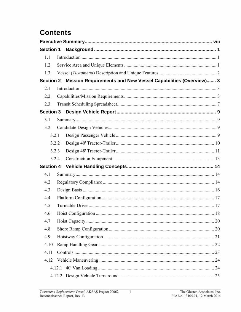
Contents Executive Summary ................................................................................................ viii
Section 1 Background ............................................................................................ 1
1.1 Introduction .................................................................................................................. 1
1.2 Service Area and Unique Elements .............................................................................. 1
1.3 Vessel (Tustumena) Description and Unique Features ................................................. 2
Section 2 Mission Requirements and New Vessel Capabilities (Overview)....... 3
2.1 Introduction .................................................................................................................. 3
2.2 Capabilities/Mission Requirements .............................................................................. 3
2.3 Transit Scheduling Spreadsheet .................................................................................... 7
Section 3 Design Vehicle Report ........................................................................... 9
3.1 Summary ....................................................................................................................... 9
3.2 Candidate Design Vehicles ........................................................................................... 9
3.2.1 Design Passenger Vehicle ..................................................................................... 9
3.2.2 Design 40' Tractor-Trailer ................................................................................... 10
3.2.3 Design 48' Tractor-Trailer ................................................................................... 11
3.2.4 Construction Equipment ...................................................................................... 13
Section 4 Vehicle Handling Concepts ................................................................. 14
4.1 Summary ..................................................................................................................... 14
4.2 Regulatory Compliance .............................................................................................. 14
4.3 Design Basis ............................................................................................................... 16
4.4 Platform Configuration ............................................................................................... 17
4.5 Turntable Drive ........................................................................................................... 17
4.6 Hoist Configuration .................................................................................................... 18
4.7 Hoist Capacity ............................................................................................................ 20
4.8 Shore Ramp Configuration ......................................................................................... 20
4.9 Hoistway Configuration ............................................................................................. 21
4.10 Ramp Handling Gear .................................................................................................. 22
4.11 Controls ...................................................................................................................... 23
4.12 Vehicle Maneuvering ................................................................................................. 24
4.12.1 40' Van Loading .................................................................................................. 24
4.12.2 Design Vehicle Turnaround ................................................................................ 25

Tustumena Replacement Vessel, AKSAS Project 70062 ii The Glosten Associates, Inc. Reconnaissance Report, Rev. B File No. 13105.01, 12 March 2014
Section 5 Arrangement Concepts ....................................................................... 27
5.1 General Configuration ................................................................................................ 27
5.2 Main Deck Arrangement Concepts ............................................................................ 27
5.2.1 Interface with Docks ........................................................................................... 27
5.2.2 Vehicle Deck Capacity ........................................................................................ 28
5.3 Passenger Accommodations Concepts ....................................................................... 28
5.3.1 Public-Workspace Matrix ................................................................................... 28
5.3.2 Boarding and Disembarking ................................................................................ 28
5.3.3 Emergency Equipment ........................................................................................ 29
5.3.4 Public Spaces ....................................................................................................... 29
5.3.5 Passenger Staterooms .......................................................................................... 30
5.3.6 Access .................................................................................................................. 30
5.4 Officer/Crew Accommodation Concepts ................................................................... 31
5.5 Food Service Concepts ............................................................................................... 31
5.6 Americans with Disabilities Act (ADA)..................................................................... 31
5.6.1 Access .................................................................................................................. 31
5.6.2 ADA Compliance – Regulatory Overview ......................................................... 32
Section 6 Regulatory Considerations ................................................................. 35
6.1 Introduction ................................................................................................................ 35
6.2 Selection of Classification Society and Class Notations ............................................ 35
6.3 International Certifications and IMO/SOLAS Certificated Systems and Equipment 37
6.4 USCG Domestic Service (USCG) Regulations .......................................................... 37
6.5 Other Applicable Guidelines ...................................................................................... 38
Section 7 Environmental Analysis ...................................................................... 39
7.1 Introduction ................................................................................................................ 39
7.2 Environmental Compliance - Air Pollution ................................................................ 39
7.2.1 Overview ............................................................................................................. 39
7.2.2 Main Propulsion Engines .................................................................................... 40
7.2.3 Diesel Generator, Lifeboat and Other Engines ................................................... 41
7.3 Environmental Compliance - Water Pollution ........................................................... 41
7.3.1 Overview ............................................................................................................. 41
7.3.2 Weatherdeck Washdown and Runoff and Above Waterline Hull Cleaning ....... 42
7.3.3 Water Run-Off from Enclosed Vehicle Spaces ................................................... 42

Tustumena Replacement Vessel, AKSAS Project 70062 iii The Glosten Associates, Inc. Reconnaissance Report, Rev. B File No. 13105.01, 12 March 2014
7.3.4 Bilge Water/Oily Water Separator Effluent ........................................................ 42
7.3.5 Ballast Water Management (BWM) For Control of Non-Indigenous Aquatic Nuisance Species .............................................................................................................. 43
7.3.6 Sewage (Black Water) and Graywater Discharge ............................................... 43
7.3.7 Shipboard Control of Garbage ............................................................................ 44
Section 8 Liquefied Natural Gas (LNG) ............................................................... 45
8.1 Summary and Recommendations ............................................................................... 45
8.2 LNG Tank Arrangement Options and Considerations ............................................... 46
8.3 Conclusion .................................................................................................................. 48
Section 9 Propulsion Study ................................................................................. 49
9.1 Introduction ................................................................................................................ 49
9.2 Purpose ....................................................................................................................... 49
9.3 Procedure .................................................................................................................... 50
9.4 Given and Assumed Parameters ................................................................................. 50
9.5 Discussion ................................................................................................................... 52
9.6 Evaluation ................................................................................................................... 56
9.6.1 30-Year Life Cycle Cost ..................................................................................... 56
9.6.2 Selection .............................................................................................................. 57
9.7 Conclusion .................................................................................................................. 59
Section 10 Weight and Stability ......................................................................... 61
10.1 Weight and Center of Gravity Estimate...................................................................... 61
10.1.1 Summary ............................................................................................................. 61
10.1.2 Lightship .............................................................................................................. 61
10.1.3 Margins ................................................................................................................ 62
10.2 Intact Stability ............................................................................................................. 63
10.2.1 Model .................................................................................................................. 63
10.2.2 Criteria ................................................................................................................. 63
10.2.3 Loads ................................................................................................................... 63
10.2.4 Preliminary Results ............................................................................................. 64
10.2.5 Future Analysis ................................................................................................... 64
10.3 Subdivision and Damage Stability ............................................................................. 64
10.3.1 Subdivision .......................................................................................................... 64
10.3.2 USCG Deterministic Method .............................................................................. 64
Tustumena Replacement Vessel, AKSAS Project 70062 iv The Glosten Associates, Inc. Reconnaissance Report, Rev. B File No. 13105.01, 12 March 2014
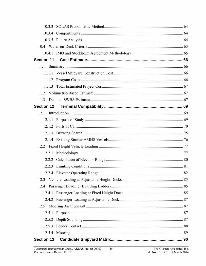
10.3.3 SOLAS Probabilistic Method .............................................................................. 64
10.3.4 Compartments ..................................................................................................... 64
10.3.5 Future Analysis ................................................................................................... 64
10.4 Water-on-Deck Criteria .............................................................................................. 65
10.4.1 IMO and Stockholm Agreement Methodology ................................................... 65
Section 11 Cost Estimate .................................................................................... 66
11.1 Summary ..................................................................................................................... 66
11.1.1 Vessel Shipyard Construction Cost ..................................................................... 66
11.1.2 Program Costs ..................................................................................................... 66
11.1.3 Total Estimated Project Cost ............................................................................... 67
11.2 Volumetric-Based Estimate ........................................................................................ 67
11.3 Detailed SWBS Estimate ............................................................................................ 67
Section 12 Terminal Compatibility ..................................................................... 69
12.1 Introduction ................................................................................................................ 69
12.1.1 Purpose of Study ................................................................................................. 69
12.1.2 Ports of Call ......................................................................................................... 70
12.1.3 Drawing Search ................................................................................................... 75
12.1.4 Existing Similar AMHS Vessels ......................................................................... 76
12.2 Fixed Height Vehicle Loading ................................................................................... 77
12.2.1 Methodology ....................................................................................................... 77
12.2.2 Calculation of Elevator Range ............................................................................ 80
12.2.3 Limiting Conditions ............................................................................................ 81
12.2.4 Elevator Operating Range ................................................................................... 82
12.3 Vehicle Loading at Adjustable Height Docks ............................................................ 85
12.4 Passenger Loading (Boarding Ladder) ....................................................................... 85
12.4.1 Passenger Loading at Fixed Height Dock ........................................................... 85
12.4.2 Passenger Loading at Adjustable Dock ............................................................... 87
12.5 Mooring Arrangement ................................................................................................ 87
12.5.1 Purpose ................................................................................................................ 87
12.5.2 Depth Sounding ................................................................................................... 87
12.5.3 Fender Contact .................................................................................................... 88
12.5.4 Mooring ............................................................................................................... 89
Section 13 Candidate Shipyard Matrix ............................................................... 90

Tustumena Replacement Vessel, AKSAS Project 70062 v The Glosten Associates, Inc. Reconnaissance Report, Rev. B File No. 13105.01, 12 March 2014
Section 14 Procurement Approaches ................................................................ 91
14.1 General Procurement Considerations ......................................................................... 91
14.2 Overview of Procurement Strategies .......................................................................... 92
14.3 Traditional Design/Bid/Build Procurement Approach ............................................... 93
14.4 Design/Bid/Build Variations ...................................................................................... 94
14.5 Traditional Design/Build Procurement Approach ...................................................... 96
14.6 Design/Build Variations ............................................................................................. 97
14.7 Detail Design by Owner ............................................................................................. 98
14.8 Summary and Recommendations ............................................................................... 99
Appendix A Coastwise Corporation Vehicle Transfer Bridge Drawing
Appendix B Tustumena Replacement Vessel General Arrangement
Appendix C Public Workspace Matrix
Appendix D Americans with Disabilities Act Report
Appendix E Regulatory Compliance Report
Appendix F Environmental Analysis Report
Appendix G Coastwise Parametric Vessel Cost Model
Appendix H Nicholson Cost Calculations
Part 1/3 Program Costs Part 2/3 Gulf Coast Costs Part 3/3 West Coast Costs
Appendix I Terminal Compatibility Study
Appendix J Transit Scheduling Spreadsheet

Tustumena Replacement Vessel, AKSAS Project 70062 vi The Glosten Associates, Inc. Reconnaissance Report, Rev. B File No. 13105.01, 12 March 2014
Revision History
Section Rev Description Date Approved
All — Initial Issue. 2/28/2014 DWL
All A Final Issue. 3/7/2014 DWL
All B Revised to incorporate AMHS comments 3/12/2014 DWL

Tustumena Replacement Vessel, AKSAS Project 70062 vii The Glosten Associates, Inc. Reconnaissance Report, Rev. B File No. 13105.01, 12 March 2014
References
1. Commercial Vehicle Size, Weight, & Permit Regulations, State of Alaska Department of Transportation, Chapter 25 Operations, Wheeled Vehicles, April 12, 2013.
2. Design Concept Report for the Day Boat ACF, Coastwise Corporation, Final Draft, February 25, 2013.
3. ASME A17.1, Safety Code for Elevators and Escalators, 2007 Edition 4. Tustumena Replacement Vessel General Arrangements, Glosten Drawing No. 1305.04-
000-01. 5. Guidelines for Construction, Installation, Maintenance and Inspection/Survey of
Means of Embarkation and Disembarkation, USCG, MSC.1/Circ.1331, 11 June 2009. 6. Alaska Class Ferry – Design Study Report, Elliott Bay Design Group.

Tustumena Replacement Vessel, AKSAS Project 70062 viii The Glosten Associates, Inc. Reconnaissance Report, Rev. B File No. 13105.01, 12 March 2014
Executive Summary
The M/V Tustumena entered service in 1964 and is near the end of its design service life. Together with the M/V Kennicott, these two ferries are the only ferries capable of serving the Alaska Marine Highway routes between Homer, Kodiak, and the Aleutian Chain. Alaska Marine Highway System (AMHS) has begun a program to replace the existing Tustumena with a new ferry, hereafter referred to as the Tustumena Replacement Vessel.
These ferries are set apart by not only their unique service route, but also their systems; no other vessel in the world shares the unique vehicle handling systems of these two ferries. The Tustumena Replacement Vessel will also require a vehicle handling system with similar capabilities. This handling system is the key driver of the new vessel configuration.
This report presents the findings from an initial design and reconnaissance effort into determining the mission requirements for a new vessel to serve on the routes presently served by the M/V Tustumena. The purpose of this report is to provide a high level summary and discussion of key vessel design drivers, regulatory requirements and cost drivers of the new vessel design.
The Tustumena Replacement Vessel design will be driven by several competing design and regulatory requirements:
Handle vehicles, heavy construction equipment, and trailers (vans) through the vessel side at docks which do not have dedicated ferry ramps or other standard loading facilities.
Interface with the standard AMHS docks in Prince William Sound and Southeast Alaska.
Serve southwest Alaska routes and docks with design challenges due to the draft limits while maneuvering at low tide and small dock sizes.
Sail in unprotected North Pacific waters and meet current American Bureau of Shipping and United States Coast Guard regulations for oceans certification.
Meet Americans with Disabilities Act requirements.
Meet new Environmental Protection Agency air emission and water emission standards.
An initial concept design for a Tustumena Replacement Vessel is presented in this report and reflects an ongoing and collaborative effort with AMHS vessel engineering and the AMHS Steering Committee. This design is the first step in seeking to balance the design requirements with operator and real world experience.
Tustumena Replacement Vessel, AKSAS Project 70062 ix The Glosten Associates, Inc. Reconnaissance Report, Rev. B File No. 13105.01, 12 March 2014
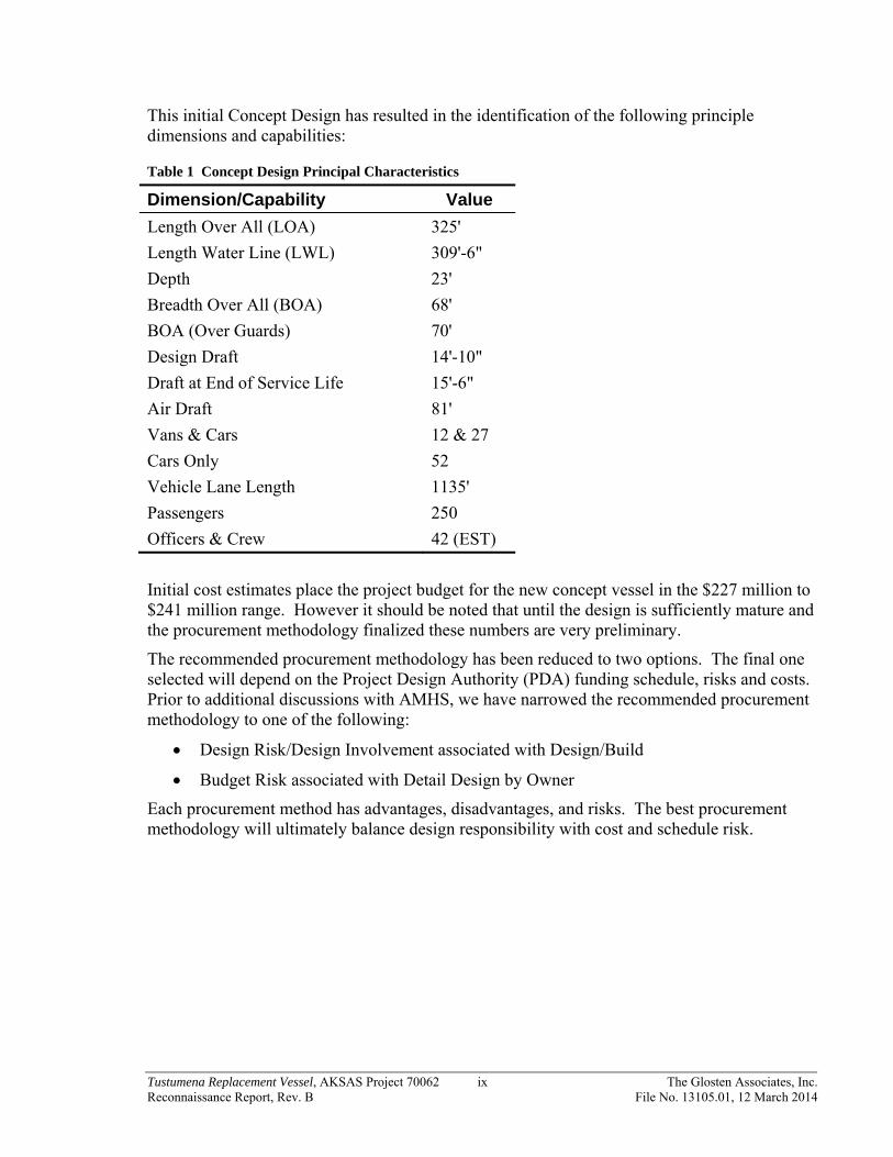
This initial Concept Design has resulted in the identification of the following principle dimensions and capabilities:
Table 1 Concept Design Principal Characteristics
Dimension/Capability Value
Length Over All (LOA) 325'
Length Water Line (LWL) 309'-6"
Depth 23'
Breadth Over All (BOA) 68'
BOA (Over Guards) 70'
Design Draft 14'-10"
Draft at End of Service Life 15'-6"
Air Draft 81'
Vans & Cars 12 & 27
Cars Only 52
Vehicle Lane Length 1135'
Passengers 250
Officers & Crew 42 (EST)
Initial cost estimates place the project budget for the new concept vessel in the $227 million to $241 million range. However it should be noted that until the design is sufficiently mature and the procurement methodology finalized these numbers are very preliminary.
The recommended procurement methodology has been reduced to two options. The final one selected will depend on the Project Design Authority (PDA) funding schedule, risks and costs. Prior to additional discussions with AMHS, we have narrowed the recommended procurement methodology to one of the following:
Design Risk/Design Involvement associated with Design/Build
Budget Risk associated with Detail Design by Owner
Each procurement method has advantages, disadvantages, and risks. The best procurement methodology will ultimately balance design responsibility with cost and schedule risk.

Tustumena Replacement Vessel, AKSAS Project 70062 1 The Glosten Associates, Inc. Reconnaissance Report, Rev. B File No. 13105.01, 12 March 2014
Section 1 Background
1.1 Introduction
This report outlines the initial design considerations for the Tustumena Replacement Vessel. The M/V Tustumena entered service in 1964 and is nearing the end of its design service life. Together with the M/V Kennicott, these two ferries are the only vessels capable of serving the Alaska Marine Highway System routes between Homer, Kodiak, and the Aleutian Chain.
AMHS has experienced increased maintenance costs and shipyard repair time to keep the M/V Tustumena in service and should anticipate the maintenance costs and required repair time to continue to increase as service life is extended. Consequently, to maintain ferry service to the communities depending on the M/V Tustumena, Alaska Marine Highway System (AMHS) will eventually face the choice to either divert the M/V Kennicott from her normal service routes to serve these routes or build a new ferry to replace the M/V Tustumena.
This report represents the findings from an initial design and reconnaissance effort into determining the mission requirements for a new vessel to serve on the routes presently served by the M/V Tustumena. An initial concept design has been developed for the Tustumena Replacement Vessel from these mission requirements. This vessel design will continue to evolve and mature as further development happens with each design cycle and phase. The purpose of this report is to provide a high level summary and discussion of key vessel design drivers, regulatory requirements and cost drivers of the new vessel design.
1.2 Service Area and Unique Elements
The docks in the service area for the Tustumena Replacement Vessel will play a large role in the vessel’s design. This vessel will operate in the AMHS fleet and will be designed to service the docks in Southwest Alaska. These docks do not have dedicated ferry ramps or other standard loading facilities found in Prince William Sound and Southeast Alaska. The docks of Southwest Alaska experience high tidal ranges, exposed locations, and severe weather conditions which the vessel will be required to overcome on a regular basis. In Southwest Alaska, all vehicle loading will be through the vessel side using a newer variation of the proven vehicle elevator/turntable design of the M/V Tustumena. The vessel will also be designed to interface with the docks in Prince William Sound and Southeast Alaska, which implies a stern door and clear decks in way of the port and starboard side doors.
The Southwest Alaska routes and docks present vessel design challenges due to the draft limits while maneuvering at low tide and small dock sizes. AMHS decided the overall length and draft of the vessel will be designed to meet all requirements without modifying the ports or docks on the Southwest routes. Therefore, the principle dimensions of the new vessel were determined based on these limitations set by AMHS.

Tustumena Replacement Vessel, AKSAS Project 70062 2 The Glosten Associates, Inc. Reconnaissance Report, Rev. B File No. 13105.01, 12 March 2014
1.3 Vessel (Tustumena) Description and Unique Features
The existing Tustumena has the following principal dimensions and characteristics:
Table 2 Tustumena Principal Characteristics
Length: 296'
Beam: 59'
Draft: 14'-5"
Service Speed: 13.8 knots
Vehicle Capacity (lane feet):
720'
Vehicle Quantity: 36
Van Quantity: 12
Passenger Capacity: 174
The M/V Tustumena and M/V Kennicott share two features which are unique to those vessels among the AMHS fleet. The first unique feature is the vehicle elevator loading/turntable system, which allows the vessel to serve docks in ports with tidal ranges up to 30 feet. This vehicle elevator design has successfully served AMHS for 50 years and drives the design of the after portion of the entire vessel. The vehicle elevator system in the Tustumena Replacement Vessel will be based on concepts from the original M/V Tustumena design (as is M/V Kennicott’s), but will incorporate modern electronics and safety features required to obtain regulatory certification.
The second unique feature of the M/V Tustumena and M/V Kennicott relative to the other AMHS ferries is the active fin stabilizers to improve vessel ride and passenger comfort in heavy seas. The Tustumena Replacement Vessel will also be equipped with an active fin stabilization system.
Tustumena Replacement Vessel, AKSAS Project 70062 3 The Glosten Associates, Inc. Reconnaissance Report, Rev. B File No. 13105.01, 12 March 2014
Section 2 Mission Requirements and New Vessel Capabilities (Overview)
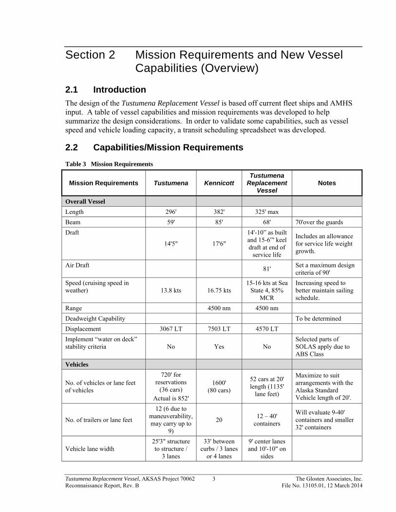
2.1 Introduction
The design of the Tustumena Replacement Vessel is based off current fleet ships and AMHS input. A table of vessel capabilities and mission requirements was developed to help summarize the design considerations. In order to validate some capabilities, such as vessel speed and vehicle loading capacity, a transit scheduling spreadsheet was developed.
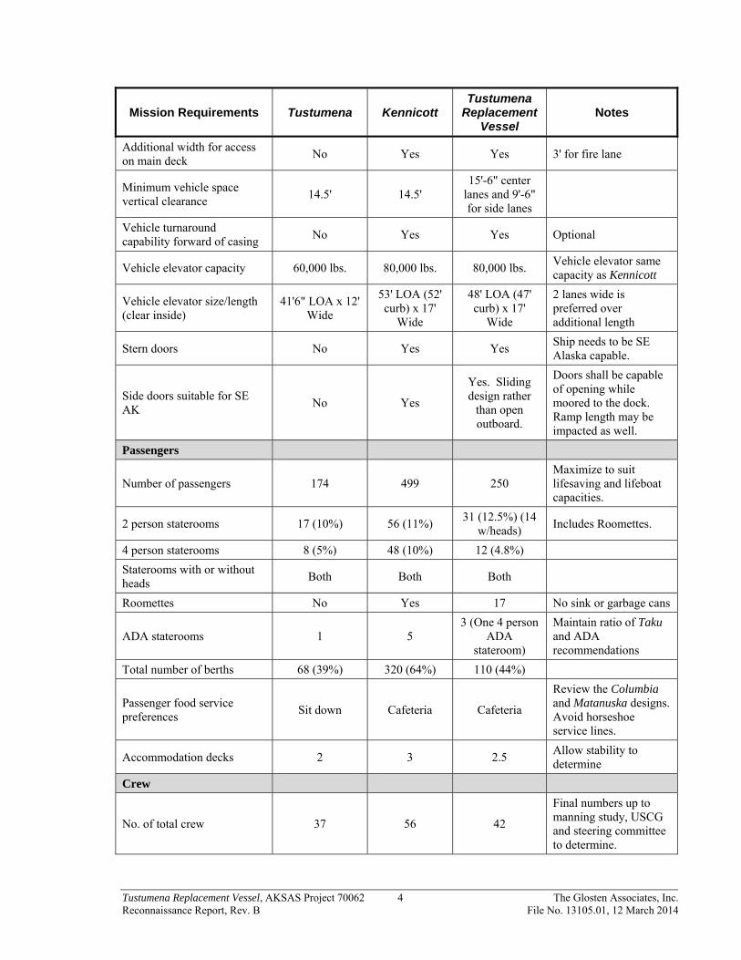
2.2 Capabilities/Mission Requirements
Table 3 Mission Requirements
Mission Requirements Tustumena Kennicott Tustumena
Replacement Vessel
Notes
Overall Vessel
Length 296' 382' 325' max
Beam 59' 85' 68' 70'over the guards
Draft
14'5" 17'6"
14'-10” as built and 15-6”' keel draft at end of
service life
Includes an allowance for service life weight growth.
Air Draft 81'
Set a maximum design criteria of 90'
Speed (cruising speed in weather) 13.8 kts 16.75 kts
15-16 kts at Sea State 4, 85%
MCR
Increasing speed to better maintain sailing schedule.
Range 4500 nm 4500 nm
Deadweight Capability To be determined
Displacement 3067 LT 7503 LT 4570 LT
Implement “water on deck” stability criteria No Yes No
Selected parts of SOLAS apply due to ABS Class
Vehicles
No. of vehicles or lane feet of vehicles
720' for reservations
(36 cars) Actual is 852'
1600' (80 cars)
52 cars at 20' length (1135'
lane feet)
Maximize to suit arrangements with the Alaska Standard Vehicle length of 20'.
No. of trailers or lane feet
12 (6 due to maneuverability, may carry up to
9)
20 12 – 40'
containers
Will evaluate 9-40' containers and smaller 32' containers
Vehicle lane width 25'3" structure to structure /
3 lanes
33' between curbs / 3 lanes
or 4 lanes
9' center lanes and 10'-10" on
sides
Tustumena Replacement Vessel, AKSAS Project 70062 4 The Glosten Associates, Inc. Reconnaissance Report, Rev. B File No. 13105.01, 12 March 2014
Mission Requirements Tustumena Kennicott Tustumena
Replacement Vessel
Notes
Additional width for access on main deck
No Yes Yes 3' for fire lane
Minimum vehicle space vertical clearance
14.5' 14.5' 15'-6" center
lanes and 9'-6" for side lanes
Vehicle turnaround capability forward of casing
No Yes Yes Optional
Vehicle elevator capacity 60,000 lbs. 80,000 lbs. 80,000 lbs. Vehicle elevator same capacity as Kennicott
Vehicle elevator size/length (clear inside)
41'6" LOA x 12' Wide
53' LOA (52' curb) x 17'
Wide
48' LOA (47' curb) x 17'
Wide
2 lanes wide is preferred over additional length
Stern doors No Yes Yes Ship needs to be SE Alaska capable.
Side doors suitable for SE AK
No Yes
Yes. Sliding design rather
than open outboard.
Doors shall be capable of opening while moored to the dock. Ramp length may be impacted as well.
Passengers
Number of passengers 174 499 250 Maximize to suit lifesaving and lifeboat capacities.
2 person staterooms 17 (10%) 56 (11%) 31 (12.5%) (14
w/heads) Includes Roomettes.
4 person staterooms 8 (5%) 48 (10%) 12 (4.8%)
Staterooms with or without heads
Both Both Both
Roomettes No Yes 17 No sink or garbage cans
ADA staterooms 1 5 3 (One 4 person
ADA stateroom)
Maintain ratio of Taku and ADA recommendations
Total number of berths 68 (39%) 320 (64%) 110 (44%)
Passenger food service preferences
Sit down Cafeteria Cafeteria
Review the Columbia and Matanuska designs. Avoid horseshoe service lines.
Accommodation decks 2 3 2.5 Allow stability to determine
Crew
No. of total crew 37 56 42
Final numbers up to manning study, USCG and steering committee to determine.

Tustumena Replacement Vessel, AKSAS Project 70062 5 The Glosten Associates, Inc. Reconnaissance Report, Rev. B File No. 13105.01, 12 March 2014
Mission Requirements Tustumena Kennicott Tustumena
Replacement Vessel
Notes
No. of Ship’s Officers (single staterooms)
12 To be determined
No. of Crew (for double staterooms)
48 berths (24
singles) To be determined
Crew below Main Deck No Yes No
Crew on Main Deck Yes No No
Crew on Mezzanine forward Yes No Yes
Structure
Steel hull Steel Steel Steel
Check/evaluate ice belt considerations or some minimal ice strengthening.
Bulbous bow No Yes Yes
Helo deck No Yes Helo pickup
area only
Parallel midbody No No Yes - if no added cost
1 or 2 casings 1 1 1
Centerline or offset casing Centerline Centerline Offset preferred
Propulsion system
Twin Screw - CPP or FPP FPP CPP CPP
Geared Diesel or Diesel Electric
Geared Diesel Geared Diesel Geared Diesel 2 x 3500 BHP - 4000 BHP (EMD16-710 or equal)
Bow thruster type - tunnel or azimuthing
Tunnel Azimuthing Tunnel
Bow Thruster - electric or diesel?
Electric Electric Electric
Bow Thruster - size 600 HP 2200 HP 1000 HP
Try to apply Kennicott design criteria (30 kts), but also evaluate for higher wind speeds. Consider 1200 HP since more is better for Homer.
Electrical System
Clean power system Distributed UPS
Needed for more advanced electronics
Shaft generators No Yes No
SSDG’s Yes Yes Yes
Investigate dual-fuel engines
Number of SSDG’s 2 2 3
Tustumena Replacement Vessel, AKSAS Project 70062 6 The Glosten Associates, Inc. Reconnaissance Report, Rev. B File No. 13105.01, 12 March 2014
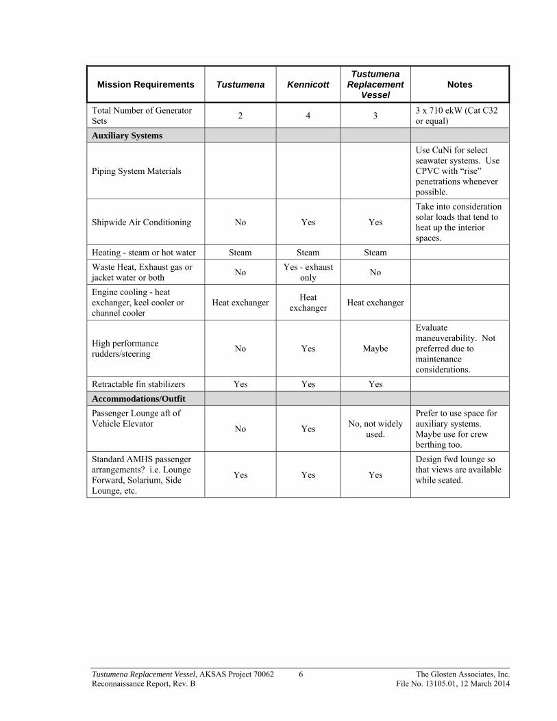
Mission Requirements Tustumena Kennicott Tustumena
Replacement Vessel
Notes
Total Number of Generator Sets
2 4 3 3 x 710 ekW (Cat C32 or equal)
Auxiliary Systems
Piping System Materials
Use CuNi for select seawater systems. Use CPVC with “rise” penetrations whenever possible.
Shipwide Air Conditioning No Yes Yes
Take into consideration solar loads that tend to heat up the interior spaces.
Heating - steam or hot water Steam Steam Steam
Waste Heat, Exhaust gas or jacket water or both
No Yes - exhaust
only No
Engine cooling - heat exchanger, keel cooler or channel cooler
Heat exchanger Heat
exchanger Heat exchanger
High performance rudders/steering
No Yes Maybe
Evaluate maneuverability. Not preferred due to maintenance considerations.
Retractable fin stabilizers Yes Yes Yes
Accommodations/Outfit
Passenger Lounge aft of Vehicle Elevator
No Yes No, not widely
used.
Prefer to use space for auxiliary systems. Maybe use for crew berthing too.
Standard AMHS passenger arrangements? i.e. Lounge Forward, Solarium, Side Lounge, etc.
Yes Yes Yes
Design fwd lounge so that views are available while seated.
Tustumena Replacement Vessel, AKSAS Project 70062 7 The Glosten Associates, Inc. Reconnaissance Report, Rev. B File No. 13105.01, 12 March 2014
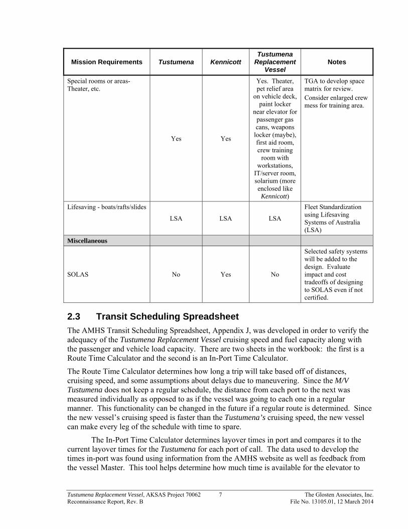
Mission Requirements Tustumena Kennicott Tustumena
Replacement Vessel
Notes
Special rooms or areas- Theater, etc.
Yes Yes
Yes. Theater, pet relief area
on vehicle deck, paint locker
near elevator for passenger gas cans, weapons
locker (maybe), first aid room, crew training
room with workstations,
IT/server room, solarium (more enclosed like
Kennicott)
TGA to develop space matrix for review. Consider enlarged crew mess for training area.
Lifesaving - boats/rafts/slides
LSA LSA LSA
Fleet Standardization using Lifesaving Systems of Australia (LSA)
Miscellaneous
SOLAS No Yes No
Selected safety systems will be added to the design. Evaluate impact and cost tradeoffs of designing to SOLAS even if not certified.
2.3 Transit Scheduling Spreadsheet
The AMHS Transit Scheduling Spreadsheet, Appendix J, was developed in order to verify the adequacy of the Tustumena Replacement Vessel cruising speed and fuel capacity along with the passenger and vehicle load capacity. There are two sheets in the workbook: the first is a Route Time Calculator and the second is an In-Port Time Calculator.
The Route Time Calculator determines how long a trip will take based off of distances, cruising speed, and some assumptions about delays due to maneuvering. Since the M/V Tustumena does not keep a regular schedule, the distance from each port to the next was measured individually as opposed to as if the vessel was going to each one in a regular manner. This functionality can be changed in the future if a regular route is determined. Since the new vessel’s cruising speed is faster than the Tustumena’s cruising speed, the new vessel can make every leg of the schedule with time to spare.
The In-Port Time Calculator determines layover times in port and compares it to the current layover times for the Tustumena for each port of call. The data used to develop the times in-port was found using information from the AMHS website as well as feedback from the vessel Master. This tool helps determine how much time is available for the elevator to

Tustumena Replacement Vessel, AKSAS Project 70062 8 The Glosten Associates, Inc. Reconnaissance Report, Rev. B File No. 13105.01, 12 March 2014
operate, and there is a function included in the worksheet in which the elevator cycle time can be changed and the impact can be seen for each port of call.
Tustumena Replacement Vessel, AKSAS Project 70062 9 The Glosten Associates, Inc. Reconnaissance Report, Rev. B File No. 13105.01, 12 March 2014
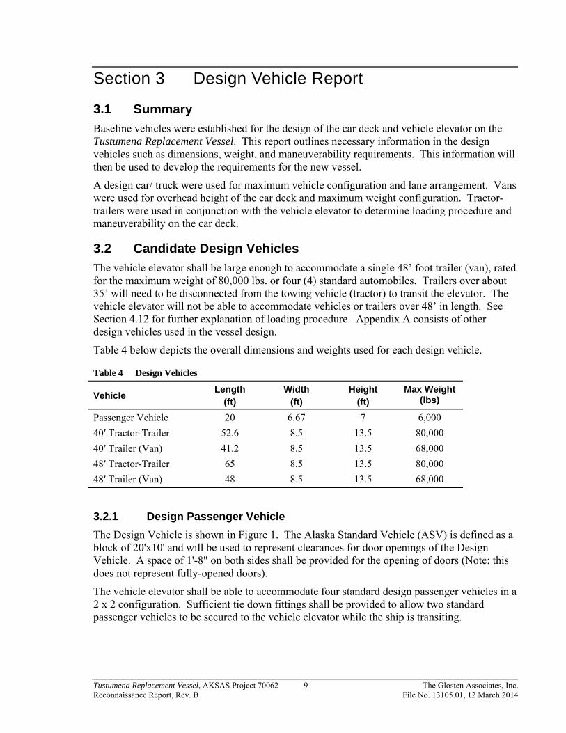
Section 3 Design Vehicle Report
3.1 Summary
Baseline vehicles were established for the design of the car deck and vehicle elevator on the Tustumena Replacement Vessel. This report outlines necessary information in the design vehicles such as dimensions, weight, and maneuverability requirements. This information will then be used to develop the requirements for the new vessel.
A design car/ truck were used for maximum vehicle configuration and lane arrangement. Vans were used for overhead height of the car deck and maximum weight configuration. Tractor-trailers were used in conjunction with the vehicle elevator to determine loading procedure and maneuverability on the car deck.
3.2 Candidate Design Vehicles
The vehicle elevator shall be large enough to accommodate a single 48’ foot trailer (van), rated for the maximum weight of 80,000 lbs. or four (4) standard automobiles. Trailers over about 35’ will need to be disconnected from the towing vehicle (tractor) to transit the elevator. The vehicle elevator will not be able to accommodate vehicles or trailers over 48’ in length. See Section 4.12 for further explanation of loading procedure. Appendix A consists of other design vehicles used in the vessel design.
Table 4 below depicts the overall dimensions and weights used for each design vehicle.
Table 4 Design Vehicles
Vehicle Length
(ft) Width
(ft) Height
(ft) Max Weight
(lbs)
Passenger Vehicle 20 6.67 7 6,000
40′ Tractor-Trailer 52.6 8.5 13.5 80,000
40′ Trailer (Van) 41.2 8.5 13.5 68,000
48′ Tractor-Trailer 65 8.5 13.5 80,000
48′ Trailer (Van) 48 8.5 13.5 68,000
3.2.1 Design Passenger Vehicle
The Design Vehicle is shown in Figure 1. The Alaska Standard Vehicle (ASV) is defined as a block of 20'x10' and will be used to represent clearances for door openings of the Design Vehicle. A space of 1'-8" on both sides shall be provided for the opening of doors (Note: this does not represent fully-opened doors).
The vehicle elevator shall be able to accommodate four standard design passenger vehicles in a 2 x 2 configuration. Sufficient tie down fittings shall be provided to allow two standard passenger vehicles to be secured to the vehicle elevator while the ship is transiting.

Tustumena Replacement Vessel, AKSAS Project 70062 10 The Glosten Associates, Inc. Reconnaissance Report, Rev. B File No. 13105.01, 12 March 2014
Figure 1 Design Passenger Vehicle and Steering
3.2.2 Design 40' Tractor-Trailer
The 40' tractor-trailer is shown in Figure 2 and Figure 3. The maximum turning angle of the inside wheel during turning maneuvers with the tractor-trailer (van) combination shall be 30° (See Figure 4). The tractor will have to be removed when loading the 40’ trailer on the vehicle elevator.
Figure 2 Design 40' Tractor-Trailer
Tractor Trailer

Tustumena Replacement Vessel, AKSAS Project 70062 11 The Glosten Associates, Inc. Reconnaissance Report, Rev. B File No. 13105.01, 12 March 2014
Figure 3 Design 40' Van
Figure 4 Design 40' Tractor-Trailer Steering
3.2.3 Design 48' Tractor-Trailer
The 48' tractor-trailer is shown in Figure 5 and Figure 6. See Figure 7 for steering angle. The tractor will have to be removed when loading the 48’ trailer on the vehicle elevator.

Tustumena Replacement Vessel, AKSAS Project 70062 12 The Glosten Associates, Inc. Reconnaissance Report, Rev. B File No. 13105.01, 12 March 2014
Figure 5 Design 48' Tractor-Trailer
Figure 6 Design 48' Van

Tustumena Replacement Vessel, AKSAS Project 70062 13 The Glosten Associates, Inc. Reconnaissance Report, Rev. B File No. 13105.01, 12 March 2014
Figure 7 Design 48' Tractor-Trailer Steering
3.2.4 Construction Equipment
For details on construction equipment, see Appendix A.
Tustumena Replacement Vessel, AKSAS Project 70062 14 The Glosten Associates, Inc. Reconnaissance Report, Rev. B File No. 13105.01, 12 March 2014
Section 4 Vehicle Handling Concepts
4.1 Summary
This section reviews the major design concepts affected by the defining feature of the Tustumena Replacement Vessel: its vehicle handling system.
The vehicle elevator for the Tustumena Replacement Vessel moves vehicles ranging from heavy trucks and construction equipment to small cars and motorcycles between the main deck and a pier level different from the main deck. At main deck level the elevator rotates to align with the vehicle lanes because there is insufficient room for vehicles to maneuver. At pier level the elevator is oriented transverse to ship centerline for vehicles to drive on and off. A transfer ramp is required to span between the elevator and pier. This transfer ramp does not need to be part of the elevator but is required to engage the elevator at pier level.
Any vehicle that can travel Alaska’s highways without special weight permits can use the elevator. However, the size of the ship limits the size of the elevator, which limits the length of vehicles that use it. The current ship arrangement limits maximum vehicle length to 48 feet.
Pedestrians can ride the elevator if it is constructed to provide an equivalent level of safety for an elevator built in accordance with the Elevator Code.
Vessel terminal time is influenced by elevator speed as all vehicles must ride it. A hoist machinery change from the winding drum elevators used on existing vessels will be required to get elevator speed faster than the code limit of 50 feet per minute for the type. Top speed for other hoist types is limited by the electric power available.
Multiple suitable vehicle elevator configurations exist for the Tustumena Replacement Vessel. All have good features and drawbacks. Probably the least technical risk would be to replicate the Kennicott elevator with minor changes to address specific concerns of the certifying authority.
4.2 Regulatory Compliance
Section 1.1.2 of the Elevator Code, Reference 3, states: “Equipment not covered by this Code includes, but is not limited to, the following: . . . . (u) platform elevators installed in a ship or offshore drilling rig and used for the purpose of loading and unloading cargo, equipment, and personnel.”
The Elevator Code can be used only as guidance for the design and construction of the vehicle elevator to achieve a level of safety equivalent to a fully compliant elevator for carrying passengers and freight. Fundamental design elements such as stress levels and factors of safety for structure and machinery can meet the Elevator Code. Door, car enclosure, pit, and hoistway configurations cannot meet the prescriptions of the Elevator Code so equivalencies must be established.
Prescriptions in the Elevator Code for car, hoistway, and door construction must be replaced by alternative, equivalent solutions to address the following issues:
1. Preventing passengers and freight from falling from the elevator. 2. Preventing passengers from leaving the elevator between stops.

Tustumena Replacement Vessel, AKSAS Project 70062 15 The Glosten Associates, Inc. Reconnaissance Report, Rev. B File No. 13105.01, 12 March 2014
3. Preventing passengers from entering the hoistway for any stop when the elevator is not at the stop.
4. Preventing passengers and freight from coming into contact with things that are not moving at the same speed as the elevator.
5. Providing safe access and working areas for maintenance workers above, around, and below the elevator and its associated machinery during all conditions of proper and improper elevator operation.
6. Excluding unauthorized people from areas where they do not belong above, around, and below the elevator and its associated machinery.
7. Preventing the elevator from descending or ascending too fast. 8. Preventing the elevator from descending or ascending uncontrollably if any single part
breaks. 9. Allowing untrained people to have unsupervised control of the elevator. 10. Providing a means for extracting passengers from the elevator in the event it becomes
stopped between landings.
Handrails and gates on the platform can address Items 1, 2 and 4, while handrails and gates on the shore ramp can address Item 3. Items 5 and 6 can be handled by a combination of passenger management, crew training, fixed barriers and sensor technology. Positive stopping devices that activate on overspeed and when cables break, whether code compliant brakes or something equivalent, can address Items 7 and 8. The elevator must never be operated by anyone other than trained crew so that Item 9 never becomes an issue. Item 10 requires procedures for emergency lowering and evacuation with crew training to execute those procedures properly.

Tustumena Replacement Vessel, AKSAS Project 70062 16 The Glosten Associates, Inc. Reconnaissance Report, Rev. B File No. 13105.01, 12 March 2014
4.3 Design Basis
The vehicle elevator consists of a hoistable platform that forms a turntable when at main deck level. The turntable can align with vehicle lanes on the main deck for loading and discharging. When oriented transversely, the platform can be hoisted to align vertically with a shore side pier. A transfer ramp between the platform and the pier completes a path for moving vehicles between the main deck and the pier. The arrangement of the ship constrains the platform to be lifted from its corners by hoisting gear located at vertical columns (king posts) near the sides of the ship on either side of doors in the main deck side shell (curtain plate).
Figure 8 Vehicle Elevator Nomenclature
The load on the platform will be mostly semi-trailers (with or without tractors, depending on length), box trucks, pickup trucks, and automobiles. Occasionally there will be construction equipment of unusual form that will tax the capability of the elevator by having a center of gravity far from the center of its footprint, loading the hoists unevenly. Consequently the design limit for the hoists should be greater than one quarter of the maximum cargo weight.
Table 5 Vehicle Elevator Vehicle Specifications
Specification Measure Units Notes
Maximum weight of cargo: 80,000 pounds see Table 4
Maximum live load at platform corner: 30,000 pounds see Section 4.7
Clear width of roadway: 17.0 feet
Minimum length of roadway: 47.0 feet
Platform clearance circle diameter: 50.7 feet
Truck wheel track: 6.0 feet
Maximum truck axle load, dual wheels: 20,000 pounds
Maximum truck axle load, single wheels: 12,000 pounds
Minimum tandem axle spacing: 4.0 feet

Tustumena Replacement Vessel, AKSAS Project 70062 17 The Glosten Associates, Inc. Reconnaissance Report, Rev. B File No. 13105.01, 12 March 2014
Specification Measure Units Notes
Minimum distance, axle to bumper: 3.3 feet
Maximum load on landing gear, per pad: 20,000 pounds see Section 4.4
Landing gear pad size 10 long x 10.5 wide inches
Truck tire ground pressure, maximum: 100 psi
4.4 Platform Configuration
The platform has a number of competing design requirements because it serves as both the hoisting platform for the vehicle elevator system and the rotating turntable on the main deck of the vessel. These design requirements include:
Must support the design load (80,000 lbs.) for the span between the lifting beams.
Must support the point loads of the trailer landing gear.
Must taper at the ends so that vehicles can transition to and from the vessel’s main deck.
Must have handrails (possibly portable) to be used for hoisting passengers outside of vehicles.
When on the vessel’s deck and acting as a turntable, must be supported by a number of wheels that align with structure below the main deck.
Must easily align/realign with both the hoisting system and the turning system for smooth transition between lifting platform and turntable.
Must be stowable completely clear of the main deck for vehicle operations in Southeast Alaska.
4.5 Turntable Drive
The platform becomes a high inertia load when it rotates to align with lanes. This high inertia load will present challenges as the platform starts and stops. Both the Tustumena and Kennicott use gear and chain reducers driving relatively small diameter pin couplings in the main deck that engage the bottom of the platform to provide both a pivot point and a rotating drive. Quick starting and stopping of the turntable generate very large torques. Torque can be reduced if the effective diameter is increased or if there is a way to introduce a torque limiting device. Greatest diameter can be achieved by mounting the drives at the corners of the platform with either friction wheels pressing on the deck or pinions engaging a low height crown gear (teeth about one inch high) on the deck that cars can drive over. The diameter of a main deck crown gear would be limited to stay out of the area where Southeast Alaska shore ramps land. Motors on the platform add complication by requiring a source of power be fed to the platform. An alternative would be to reduce the active diameter to fit the width of the platform and mount the friction wheels or pinions in recesses in the deck to engage a circular path or crown gear on the underside of the platform. Any large diameter drive scheme requires a separate center pivot.

Tustumena Replacement Vessel, AKSAS Project 70062 18 The Glosten Associates, Inc. Reconnaissance Report, Rev. B File No. 13105.01, 12 March 2014
Any device set on or in the deck must tolerate vehicles driving over it and must not represent a tripping hazard. It must be dirt tolerant. Any recess will require drains and easy access for removing dirt that falls off vehicles. A pin coupling drive through the deck requires a large diameter dirt and water seal which must be capable of maintaining the fire rating of the deck.
Friction drives do not require precise positioning relative to the platform. Without positive connection to the platform, a friction drive can slip and the rotation controls must be capable of dealing with this. However, the possibility of slip provides an inherent torque limiting feature.
Maximum peripheral velocity of the platform should be no greater than walking speed, about 4 feet per second, so people can safely run away from it. This peripheral speed works out to be approximately 1 1/3 RPM for the platform.
Table 6 Turntable Drives
Drive type Deck features Umbilical to
platform Drive location Drive torque
Pin Coupling Pin recesses, Large shaft seal
No Below main deck High
Medium dia. crown gear on deck
Low height ring of gear teeth, Pivot pin recess
Yes On platform Medium
Medium dia.crown gear under platform
Low height projection of pinion teeth, Pivot pin recess
No Recessed in main
deck Medium
Large dia. crown gear on deck
Low height ring of gear teeth, Pivot pin recess
Yes On platform Low
Medium dia. friction drive against deck
Pivot pin recess Yes On platform Medium,
self limiting
Medium dia. friction drive against platform
Low height projection of drive wheel, Pivot pin recess
No Recessed in main
deck Medium,
self limiting
Large dia. friction drive against deck
Pivot pin recess Yes On platform Low, self limiting
4.6 Hoist Configuration
The platform must be hoisted by carriers at each end (or side in ship coordinates). The carriers must have some sort of timing feature so that they rise simultaneously and keep the platform level. The carriers need to be guided vertically by king posts or structure of adequate strength to resist transverse loads due to roll, pitch, trim, and heel. When the platform is on the main

Tustumena Replacement Vessel, AKSAS Project 70062 19 The Glosten Associates, Inc. Reconnaissance Report, Rev. B File No. 13105.01, 12 March 2014
deck, the carriers must drop below the platform side beams and disengage so the platform can be rotated. When the platform is rotated out of the way, the carriers can be raised so as not to obstruct the main deck in way of the side port doors.
King post height must be sufficient to guide the platform for its full 34' rise plus an additional half foot for carrier disengagement. If the king posts are tied together by structure at their tops, the king post height above the main deck must be greater than 50 feet. If the king posts are “free standing,” the king post height above the main deck may be as little as 38 feet. Depending upon the hoisting scheme, king posts can be foldable to fit below a closed hatch at the Cabin Deck level.
There are several platform hoisting options:
Winding drum winch.
Roped hydraulic cylinders.
Direct-acting hydraulic cylinders.
Screw columns.
Traction winches are impractical because of the required drum diameter, the required location of the winch at the top of the hoistway, and the need for a counterweight nearly as heavy as the platform. An elevator with a winding drum winch is limited by the Elevator Code, ANSI A17.1 paragraph 2.24.1, to a hoisting and lowering speed of 50 feet per minute. Hydraulic and screw column elevators do not have this speed restriction.
Hoisting with a winding drum winch or roped hydraulic cylinders requires the carriers be fitted with brakes to stop the platform from falling in the event of a broken cable or runaway winch. The brakes must be applied evenly so the platform remains level. Hoisting with direct acting hydraulic cylinders does not require safety brakes but some scheme to coordinate cylinder extension is required for normal operation and emergency lowering. Hoisting with screw columns does not require safety brakes but does require coordination of the hoists to keep the platform level.
Hydraulic hoists can be arranged to provide a counterbalance function that can support the dead weight of the carriers. With suitable controls, it may be able to offset the dead weight of the platform as well. Neither winding drum winches nor screw columns can have a counterbalance function.
If the electric motors in the hoists are arranged to regenerate power into the ship’s electrical system, the overall system efficiency is enhanced as energy is recovered when the platform is lowered. Flow losses in the hydraulic piping and controls will make energy recovery from hydraulic hoists difficult.

Tustumena Replacement Vessel, AKSAS Project 70062 20 The Glosten Associates, Inc. Reconnaissance Report, Rev. B File No. 13105.01, 12 March 2014
Table 7 Hoist Configurations
Hoist type Speed limit
Brakes required
Overspeedrequired
Coordination mechanism
required
Folding king
posts possible
Energy recovery possible
Winding drum winch (Tustumena, Kennicott)
50 ft/min Yes Yes No No Yes
Winch w/ compression link
50 ft/min
Yes Yes No Yes Yes
Direct hydraulic None No No Yes Yes No
Roped hydraulic None Yes Yes Yes Yes No
Screw column None No No Yes No Yes
4.7 Hoist Capacity
The large platform makes off center loading for 80,000 pound live loads a real possibility. There are two vehicle lanes, but when the load is a large truck or piece of construction machinery, it should straddle the lanes. Should this not occur and the load is parked in one lane with the other lane empty, two of the hoists will share approximately 58,000 pounds of live load. With the possibility of some load shifted off center longitudinally, peak live load at any corner of more than 29,000 pounds is very possible. Total hoist power and descent brake ratings can be based on 80,000 pound live load but hoist wires and safety brakes should be based on corner load. A design live load of 30,000 pounds for the hoist at each corner seems reasonable and prudent.
4.8 Shore Ramp Configuration
The shore ramp spans from the end of the platform to the pier. The outboard end rests on the pier deck and the inboard end can either rest on the elevator platform or be supported directly by the king posts.
If the ramp rests on the platform, each hoist’s live load capacity must be increased by one fourth of the empty weight of the shore ramp. Also, if the shore ramp rests on the platform when the platform is in the up position, it can hang by chains or ropes from the king posts when the platform is on the main deck.
If the ramp has direct support from the king posts, it still can be lifted by the platform and the hoist live load capacity is not influenced by the ramp weight.
The shore ramp should be as short as possible to reduce its weight and the required hoisting capacity of its handling gear. Its maximum width must be slightly less than 17 feet if it is to rest on the platform’s roadway. If it is supported directly by the king posts during vehicle loading, its maximum width is dictated entirely by stowage and handling considerations. The shore ramp can be single-ended, meaning one end is always on the pier, and the other end is always on the ship. If there is just one single-ended ramp, it must be rotated to suit the side of

Tustumena Replacement Vessel, AKSAS Project 70062 21 The Glosten Associates, Inc. Reconnaissance Report, Rev. B File No. 13105.01, 12 March 2014
the ship where loading takes place. With two single-ended shore ramps, each would always be oriented properly.
Side port doors can be configured to serve as single-ended shore ramps. The net weight of two ramp/doors is greater than two doors and one double ended ramp because the pressure related to wheel loads is far greater than the design pressure for a watertight door. The door opening mechanism which must also be a ramp handling mechanism may result in a less complex ship than one where door handling and ramp handling are separate functions. There may also be arrangement benefits to having ramp/doors that open outward and slide up instead of regular doors that open into the vehicle space and slide forward.
Table 8 Shore Ramp Configurations
Platform Type
Stowage on platf. roadway
Stowage on
hoistway hatch
Ship end supported by platform
Ship end supported
by king posts
Must rotate to
shore side
Weight ranking 1 = min
<17' wide double end ramp
Yes
Yes Yes (Tustumena, Kennicott)
No No 1
>17' wide double end ramp
No Yes No Yes No 2
>17' wide single end ramp
No Yes No Yes Yes 2
Side door/ramp
No No No Yes No 4
4.9 Hoistway Configuration
The hoistway arrangement has several key design concepts: its doors (watertight or weathertight), its top (closed or open), and its kingposts (high or low, and fixed or hinged).
Any hoistway arrangement must have watertight doors from the Main Deck to the Cabin Deck and the portions of the Cabin Deck outboard of the hoistway must be hinged to clear the access to the elevator platform.
The hoistway can be enclosed above the Cabin Deck with steel transverse bulkheads and a fixed top similar to the Kennicott. A fixed top must provide 49' clear height above the main deck to clear a truck on the fully raised platform. High fixed kingposts work well as corner supports for an enclosed hoistway. An enclosed hoistway has more weight and windage than an open hoistway so the enclosed hoistway reduces stability. An enclosed hoistway needs weather tight doors on the sides to complete the enclosure from the Cabin Deck to the fixed top.

Tustumena Replacement Vessel, AKSAS Project 70062 22 The Glosten Associates, Inc. Reconnaissance Report, Rev. B File No. 13105.01, 12 March 2014
Weathertight doors can be hinged panels or roller curtains. Hinged panels require large clearances for swinging and may be heavier than the roller curtains. Roller curtains have many moving parts and places for collecting corrosive spray and dirt.
The hoistway can be open above the Cabin Deck with a weather tight hatch in the Cabin Deck similar to the Tustumena.
High, fixed king posts provide good supporting structure for an enclosed hoistway. Low and hinged king posts make supplemental structure necessary for supporting an enclosed hoistway. Hinged king posts in an open hoistway work best for keeping elevator components below a weather tight hatch at the Cabin Deck. High or low, non-hinged king posts in an open hoistway may make weather sealing the Cabin Deck hatch difficult.
Table 9 Hoistway Configurations
Hoistway Type King post
type
Doors above
Cabin Deck
Hatch in Cabin Deck
Hatch leakage potential
Stability ranking 1 = min
Enclosed (Kennicott)
High fixed
Yes No No 1
Open (Tustumena)
High fixed No Yes Yes 2
Open Low fixed No Yes Yes 3
Open Hinged No Yes No 4
4.10 Ramp Handling Gear
The shore ramp can be moved over the side from a hoist on a trolley supported over the platform from cross structure on high fixed king posts. When a trolley is used, its support beam can either be fixed and longer than the beam of the ship or the support beam can slide transversely to reach the desired outboard extension without being longer than the beam of the ship.
The shore ramp can be moved over the side using a knuckle boom crane mounted on the Cabin Deck or the Sun Deck, provided the king posts are short enough for the crane boom to swing over the top when handling the ramp. Cranes are not compatible with an enclosed hoistway. When cranes are used, there must be one on each side of the vessel to keep the reach within practical limits of commercial offerings.
If the shore ramp is also a watertight side door, the ramp handling gear must integrate with the door function. Ramp/doors can be moved to and from the open position using the unloaded elevator to provide lift. Swinging the ramp out to rest on the pier can be done using tackles from the tops of the king posts to the upper corners of the door or with hydraulic cylinders between the door and sliding hinge carriers on the king posts.

Tustumena Replacement Vessel, AKSAS Project 70062 23 The Glosten Associates, Inc. Reconnaissance Report, Rev. B File No. 13105.01, 12 March 2014
Table 10 Ramp Handling Methods
Handling Method King post type Number required
Trolley hoist (Tustumena, Kennicott) High fixed 1
Crane Low fixed or hinged 2
Tackle (only with door/ramp) High or low fixed 4
Hydraulic cylinder (only with door/ramp) High or low fixed 4
4.11 Controls
The Elevator Code is based on passengers entering an elevator car and pushing a button to go to a selected floor. This fully automatic operation is not safe for the vehicle elevator for the Tustumena Replacement Vessel because of the variability of loading conditions at different ports at different times. The command to raise or lower or rotate the platform must be made by a trained member of the ship’s crew.
Where the hoist configuration would require safety brakes to meet the Elevator Code, brakes must be fitted with all of the stop features and reset requirements in the Elevator Code.
Reliability
Because there is no room on the Main Deck for either a pit or a platform overrun, it is critical that hard landings of the elevator are prevented by extra reliability in the controls. The controls should not rely on the suspension of the wheels under the platform to assure soft landings. Acceleration during normal and emergency stops should not exceed the limits in the Elevator Code.
Where electric motors drive mechanical (as opposed to hydraulic) hoists, they should be fitted with variable frequency drives to provide ramped acceleration and dynamic braking. Hoists must have automatic devices, which could be brakes that lock the platform in position when power is shut off and when the platform is stopped at a loading level above the main deck. These devices must be capable of being released in a controlled manner to allow the platform to be lowered very slowly to the main deck without power.
Location
Operator controls should be located where the whole operation of loading and hoisting can be observed. The shore end of the platform and a control cab at the top of the hoistway are suitable locations. A station on the main deck can be useful for controlling turntable rotation but will have its view of loading from a pier restricted by the platform itself. Any control station on the main deck should be limited to turntable functions and stopping lowering in case there is an obstruction below the platform.
Speed
Operator controls for the elevator must have, as a minimum, up and down jog controls that move the platform at a low speed such as 5' per minute with limit switches at the deck and top of the hoistway to initiate deceleration and stop the platform at the ends of travel. Up and down jog controls would be used for lifting and lowering the shore ramp.

Tustumena Replacement Vessel, AKSAS Project 70062 24 The Glosten Associates, Inc. Reconnaissance Report, Rev. B File No. 13105.01, 12 March 2014
Type
Operator controls for the turntable must have, as a minimum, right hand and left hand rotation jog controls that move the platform a low peripheral speed such as one inch per second or 0.03 RPM.
Beyond the basic jog controls, the hoist and rotation can have any combination of manual or automatic control over acceleration, hoist distance, hoist speed, descent speed, rotational acceleration, platform rotation angle, and rotation speed. The only regulatory limitation is hoist and descent speed for winding drum elevators.
The simplest controls are the same as the jog controls but with speeds set to maximum. Stopping the platform at the shore ramp would occur upon operator command.
The next simplest control is joystick control with infinitely variable speed from jog speeds to maximum allowable. The four directions of the joystick would correspond to “up,” “down,” “rotate right,” and “rotate left.” Increased deflection would correspond to increased speed. Limit switches would disable rotation functions when the platform is off the main deck and hoist functions when the platform is not aligned with the hoists.
The most automatic control scheme mimics the controls of a building elevator. There would be a pushbutton for the pier and each car deck lane. Pushing a button for a destination would automatically rotate and hoist the elevator from aligned with a lane to aligned with the shore ramp, or automatically lower and rotate as appropriate. Such controls would incorporate a programmable logic controller with platform height and rotation sensors and manual or sensor input of the elevation of the shore ramp. Automatic controls could reduce operator workload if they are reliable. Automatic controls would also make operator inattention highly likely. Automatic controls make proximity sensors an absolute necessity to detect obstructions around or under the platform to stop motion before any harm is done. A form of automatic controls for hoist height was provided with the Kennicott’s elevator.
4.12 Vehicle Maneuvering
A brief summary of vehicle loading/unloading procedures was developed for the Main Deck Arrangements. The maneuvering procedures aided in determining feasibility of arrangements with the offset casing layout. Loading/unloading of the 40' vans and design vehicle turnaround capabilities were determined for the most critical areas of the Main Deck arrangement.
4.12.1 40' Van Loading
The loading scenario utilized for the vans were the aft three nearest the turn table. Loading the remaining nine vans was deemed feasible if the aft three, in the most difficult scenario, could be completed. Loading procedures were performed Port to Starboard and checked for interference with other vehicles or structure. No interferences were determined.

Tustumena Replacement Vessel, AKSAS Project 70062 25 The Glosten Associates, Inc. Reconnaissance Report, Rev. B File No. 13105.01, 12 March 2014
Figure 9 Port Aft 40' Van Loading
Figure 10 Center Aft 40' Van Loading
Figure 11 Starboard Aft 40' Van Loading
4.12.2 Design Vehicle Turnaround
When loading and unloading it is beneficial to allow drive-around capabilities on the Main Deck. This arrangement would speed up loading/unloading and ensure safer maneuvering.

Tustumena Replacement Vessel, AKSAS Project 70062 26 The Glosten Associates, Inc. Reconnaissance Report, Rev. B File No. 13105.01, 12 March 2014
The design vehicle/truck was used in this analysis with the outside lines representing width of the vehicle with mirrors. Turnaround capability was verified without any interference.
Figure 12 Starboard to Port Turnaround Down Center
Figure 13 Starboard to Port Turnaround Outside Lane
Figure 14 Port to Starboard Turnaround

Tustumena Replacement Vessel, AKSAS Project 70062 27 The Glosten Associates, Inc. Reconnaissance Report, Rev. B File No. 13105.01, 12 March 2014
Section 5 Arrangement Concepts
5.1 General Configuration
This section reviews the major design concepts for the arrangements of the overall vessel, as well as its main deck, passenger accommodations, officer/crew accommodations, food service areas, and ADA accessibility.
The design goal for the vessel configuration was to maximize revenue spaces while separating functions and meeting the new manning regulations. Appendix B shows the proposed vessel general arrangements.
The desire to maximize vehicle space precludes having staterooms on the main deck and also makes access to spaces below the deck inconvenient. To create the space needed for crew accommodations required the adoption of mezzanine decks at the sides of the vehicle space. The mezzanines are supported structurally by the off-center casing and a line of stanchions.
With the crew spaces on the mezzanine deck it was decided to place all passenger cabins on one deck, and dining and lounge spaces above that deck. The top deck has space for the officer cabins and the solarium.
The lounges are forward in the traditional AMHS arrangement and are high enough to see over the bulwarks. The galley serves both the crew and the passengers and serves to divide the two functions. The officer staterooms are separated from the solarium and are accessed by their own stairways.
For the preliminary design, the design with the smallest beam but with adequate stability was selected. The beam was minimized to reduce propulsion requirements and to produce a softer ride with less potential slamming. It was felt that if the arrangements worked at the narrow beam then a wider beam could be implemented easily if later required.
The beam selected is too narrow to arrange six lanes of vehicles with an additional fire lane. A five lane arrangement was chosen instead, which allows generous side lanes under the mezzanines and works well with an off center casing.
5.2 Main Deck Arrangement Concepts
5.2.1 Interface with Docks
The new vessel is required to interface with all docks both of Southwest Alaska and Bellingham, Washington. The new vessel will therefore require a vehicle elevator capable of meeting the tidal range height as well as a stern ramp designed to support the current docking configuration. It is not possible to modify docks and the vessel is required to interface with all loading configurations at each dock.
The Main Deck arrangement gathered elements from the current M/V Tustumena and M/V Kennicott to accomplish dock interfaces. A stern loading door will allow four lanes of cars to enter/exit through the aft of the vessel. This drives the vessel stern relatively wide at the Main Deck. Just forward a vehicle elevator will expand the breadth of the vessel and allow access from the dock through either port or starboard loading doors.
Tustumena Replacement Vessel, AKSAS Project 70062 28 The Glosten Associates, Inc. Reconnaissance Report, Rev. B File No. 13105.01, 12 March 2014
The vehicle elevator was originally considered to fit 53' trailers, similar to the M/V Kennicott. However, the layout of the structure made this impossible without widening the vessel beyond the 70' beam. Discussions with the AMHS Steering Committee indicated 53' trailers were uncommon and not required. The decision was made to maintain the deck dimensions based on a slightly smaller elevator.
5.2.2 Vehicle Deck Capacity
The goal of the new design is to maximize the main source of revenue: the number of cars held on the Main Deck. The minimum design requirements are to maintain the same number of lane feet as the current M/V Tustumena (720') and the capability of loading twelve 40' vans.
Vans require significant overhead height to detach from the tractors. Structural members are often large for the long spans in the overhead of the vehicle deck. These requirements pushed the height from the Main Deck to the Cabin Deck to around 20 feet.
A centerline casing was originally discussed as a majority of AMHS vessels are designed in this manner. The large height requirement for the vehicle deck created a lot of wasted space with this configuration as the entire deck would need to be full height. It was decided to pursue an offset casing to create a Mezzanine Deck, which would fulfill the van capacity requirement while allowing more deck area for other vessel requirements. See Section 5.4 for further discussion on need for a Mezzanine Deck.
A 36" fire lane is required to run the length of the deck, which is not found on the current vessel. Based on optimizing the lane configuration a minimum of 9' lane widths was utilized in the full height area for vans and large cars. Lane widths were maximized near 10’ for outboard lanes under the mezzanines to allow more room for access. Currently the area under the M/V LeConte mezzanines is very narrow and often problematic. It was important to provide more room in these areas for crew and passenger comfort.
The vehicle elevator will also be capable of loading two lanes of cars, making it slightly wider than the current design. This will encroach on deck area of the vessel but will make loading of cars significantly faster.
5.3 Passenger Accommodations Concepts
5.3.1 Public-Workspace Matrix
A matrix of all spaces in the vessel was developed to compare the proposed replacement with the original M/V Tustumena design. Please see Appendix C.
5.3.2 Boarding and Disembarking
The flow of passengers is envisioned so any person entering shall have an obvious path through the vessel. The forward elevator and stair tower are considered the main means of boarding. The main stair tower leads up and opens into the Cabin Deck near the Foyer and Purser’s Office. Passengers boarding in cars will be directed to the forward part of the casing while passengers on foot will be directed to the boarding ramp which leads directly to the Foyer on the Cabin Deck. This allows the Purser’s Office to be the main point of entry for everyone. Cabins can then be purchased and found on the same deck. Those passengers not

Tustumena Replacement Vessel, AKSAS Project 70062 29 The Glosten Associates, Inc. Reconnaissance Report, Rev. B File No. 13105.01, 12 March 2014
purchasing cabins will continue up to the Boat Deck where the remainder of public spaces are located.
In extreme tidal ranges a sliding boarding ramp will allow passengers on foot to board at any deck. A foyer is positioned on every level for boarding at Frame 70-75. If the Cabin Deck is not the boarding location passengers will be directed to the Purser’s Office by utilizing the main forward stair tower.
The solution of using two elevators for passengers complicates arrangements, but segregates passengers and crew, and is thus an ideal solution. The arrangement of passenger elevator forward and service elevator aft was dictated by practicality. The service elevator was required to access the store rooms below the Main Deck and the Galley on the Boat Deck directly. Placing the service elevator forward would require moving the Galley as well as stores forward of the machinery spaces, which was briefly discussed but deemed a less advantageous arrangement.
5.3.3 Emergency Equipment
Lifeboats were originally sized for approximately120 persons based on requirements by USCG. It was later decided to limit the vessel to 50 nautical miles from shore, which allows lifeboats to be reduced to 48 persons on each side. Smaller lifeboats are easier to fit into the arrangements and additional life rafts will be carried in place of larger boats. The lifeboats will be stored aft of the Solarium in order to not disrupt view for passengers or line of sight from the Wheelhouse.
The lifeboats will also be registered as rescue boats which allows for a single service boat that will be operated by crane and stowed above the aft elevator control room, similar to the current M/V Tustumena arrangement. This will give more flexibility and not require an additional rescue boat on each side of the vessel.
Lifeboats will be boarded on the Boat Deck in order to allow mustering in public spaces such as the Dining Area and forward lounges. Two main stair towers will be sized appropriately on each side of the Main Vertical Zone (MVZ) to allow passenger embarkation. Crew will be required to board using the ramp next to the lifeboat and lower the lifeboats down for boarding from Boat Deck level.
Evacuation slides will be used for boarding the life rafts from the Boat Deck. Liferaft Systems Australia (LSA) evacuation slides contain a single 100 person raft in each deployment container. Additional rafts will be placed to the side of the slides for deployment in case of emergency. The evacuation slide system has a maximum height above waterline of 44.6’. This height requirement must be maintained in the lightest undamaged sea-going condition and take into account unfavorable conditions of list and trim. The Boat Deck meets the requirements of the slide while allowing easy access from mustering stations. Originally the evacuation slides were placed on a lower deck but access in emergency dictated moving them to the same level as the lifeboats.
5.3.4 Public Spaces
Public space areas were scaled from the current M/V Tustumena arrangements based on increased passenger capacity. The initial intention was to start with the same spaces as the current vessel and add any necessary spaces based on AMHS input. It was indicated public
Tustumena Replacement Vessel, AKSAS Project 70062 30 The Glosten Associates, Inc. Reconnaissance Report, Rev. B File No. 13105.01, 12 March 2014
spaces aft of the vehicle elevator on other vessels were not utilized and these should be reserved for crew or machinery areas.
AMHS indicated the Galley/Dining will be cafeteria style, very similar to the arrangement on the M/V Columbia. This style dictated arrangements would be best with the dining area just forward of the Galley. A single serving line will provide hot food on one side and cold beverages on the other. The cashier will be placed at the end before entering the Dining Area. The serving line will be closable while still maintaining access to the Dining Area for passenger use at all times.
The goal during development of arrangements was to segregate the public areas from the passenger cabins as well as the crew spaces. This was mainly accomplished by having a dedicated Cabin Deck and placing most public spaces on the deck above. The Galley on the Boat Deck is able to split public spaces forward and all crew/officer spaces aft. This also allows the Forward Observation Lounge to be above the Cabin Deck in order to see over the bulwarks. It was briefly considered to include public spaces on the Cabin Deck but this would require adding a void of at least 36" to raise the forward observation lounge. It was determined more expensive and complicated and was not pursued further.
5.3.5 Passenger Staterooms
Maximizing the number of passenger staterooms was considered crucial for revenue generation. AMHS indicated passenger staterooms allocation should be based on the current M/V Tustumena with a few deviations. Minimizing four person rooms while adding more two person staterooms with private toilet/shower modules was thought to fit passenger needs better. Roomette solutions were also considered as it was thought they would sell better than on the M/V Kennicott because of the quick overnight trips on the Southwest run. AMHS reiterated it is not acceptable to have any lavatories without heads in the cabins.
The size of passenger staterooms was taken from the M/V Kennicott, as the newest model of staterooms in the fleet. This gave a base design and will need to be adjusted based on the frame spacing of the new vessel and spacing of deep frames.
5.3.6 Access
Original concepts split the Main Vertical Zone (MVZ) bulkhead (i.e. fire boundary) down the middle of the vessel. Originally, a single stair tower was positioned to serve both sides of the MVZ. This stair tower would be required to meet special regulations for width based on passenger egress and fire protection. Boarding of passengers into the main foyer on the Cabin Deck was required to spread the breadth of the vessel. Due to the casing and foyer requirements, arrangements became too complicated to support a single stair tower approach.
The original stair tower was split into two smaller stair towers on each side of the MVZ. These will be sized for the appropriate number of people required to utilize them for embarkation of lifeboats in an emergency.
American Bureau of Shipping (ABS) requires SOLAS calculations for landing area requirements of the stair towers. This requirement will drive the area of the stair towers to be quite large but was considered in the design.

Tustumena Replacement Vessel, AKSAS Project 70062 31 The Glosten Associates, Inc. Reconnaissance Report, Rev. B File No. 13105.01, 12 March 2014
5.4 Officer/Crew Accommodation Concepts
Regulations require crew to be placed on the Main Deck or above. In order to maximize vehicle space and revenue generation, it was decided not to place crew staterooms on the Main Deck. In order to accommodate the number of crew, a mezzanine level was required to allow enough deck area. Mezzanines force arrangements into an offset casing for practicality of structure.
The initial design replicated the same officer stateroom space as the current M/V Tustumena on the Solarium Deck. The number of crew staterooms on the Mezzanine level was maximized in order to allow as many single person staterooms as possible.
AMHS requested additional space for crew training as well as a large meeting room. These will be added to the arrangements but kept away from public spaces if practical.
5.5 Food Service Concepts
Food service concepts were developed by Directions in Design, Inc. The original design was modelled after the cafeteria style of the M/V Columbia. Passenger flow was modelled in a clockwise fashion through the space to the cafeteria line and back to the seating area. It was also important to be able to close off the cafeteria line while still maintaining access to the dining area for passenger use during off hours. The capacity of the dining area was maximized to 102 people, slightly more than the current M/V Tustumena by percentage of passenger capacity.
A side serving line was reserved for crew and officer messes. Access will be granted through a door from the dining area or from the aft stair tower. This arrangement will allow segregation of crew areas and will lead directly from the galley into the crew and officer mess area.
The bar area was originally placed forward as a side lounge. Direction from AMHS indicated the bar was staffed by the same personnel in charge of the dining area. The staffing arrangement dictated moving the bar closer to the dining area while still retaining privacy for passengers using the area. The bar was later dropped in favor of additional seating for the cafeteria.
5.6 Americans with Disabilities Act (ADA)
5.6.1 Access
The intent of the vessel design is to meet the ADA requirements and provide the same experience for disabled persons on the vessel to the extent possible within the limitations imposed by the marine environment. A portion of staterooms and heads will be reserved for ADA passengers according to the regulations.
The forward passenger elevator was carried all the way to the Solarium deck in order to allow access for everybody. This does change arrangements for officer cabins and access to the deck as the offset casing puts the elevator almost to the edge of the deck. It was important to incorporate this capability in the design and some side effects were inevitable.

Tustumena Replacement Vessel, AKSAS Project 70062 32 The Glosten Associates, Inc. Reconnaissance Report, Rev. B File No. 13105.01, 12 March 2014
5.6.2 ADA Compliance – Regulatory Overview
A summary table outlining the Accessibility of the current conceptual vessel general arrangements is included in Appendix C.
A full report addressing the ADA regulations is included in Appendix D.
The accessibility guidelines for passenger vessels covered by the Americans with Disabilities Act (ADA) will, in the future, be set forth in an appendix to the Passenger Vessels Accessibility Guidelines, US Code of Federal Regulations, Title 36, Part 1196. Currently however, Part 1196 of CFR Title 36 is “reserved.” Once these guidelines are established, the U.S. Department of Transportation (DOT) and U.S. Department of Justice (DOJ) are then required to issue accessibility standards for the construction of passenger vessels covered by the ADA that are consistent with the Part 1196 guidelines. We note here that the DOT regulations applicable to passenger vessels, addressed in 49 CFR 39 - Transportation for Individuals with Disabilities: Passenger Vessels, discuss requirements for providing assistance to passengers with disabilities, but the subpart intended to deal with actual accessibility design standards for vessels (Subpart E - Accessibility of Vessels) is currently “reserved”. Nonetheless, passenger vessel owners and operators will be required to comply with the published standards, once they are promulgated.
The Passenger Vessel Association is presently developing a “proposed” comprehensive set of guidelines that contain scoping and technical requirements for accessibility to passenger vessels by individuals with disabilities. For now, the proposed Passenger Vessel Association Accessibility Guidelines (hereafter referred to as “AGs”) is the primary useful source for detailed ADA compliance guidelines for passenger vessel design. Presumably, these guidelines will form the basis for the Part 1196 guidelines and related DOT and DOJ standards for passenger vessels to be included in the CFR in the future.
At 237 pages, the AGs are extensive and cover the gamut of accessibility issues in great detail. While our design team will be monitoring design carefully to ensure compliance with all applicable provisions of the AGs, the following are considered the most germane accessibility guidelines pertaining to the preliminary design of the Tustumena Replacement Vessel:
Boarding System - The vessel will be required to have a boarding system and “onboard accessible routes” that ensure that each passenger deck and passenger amenities (e.g., staterooms/roomettes, solarium, dining room, child play area, public restrooms, etc.) within each deck are ADA accessible. As a practical matter, the only means by which each passenger deck can be connected for ADA accessibility is through use of a passenger elevator system. Only one accessible route is required between decks however, meaning that only one elevator system would be required for passenger use.
Stateroom Features - The Tustumena Replacement Vessel design currently provides for 46 passenger staterooms, including roomettes. Based on this total number of staterooms, two (2) staterooms with “mobility” features and four (4) with “communication” features1 will have to be provided. At least one of the staterooms has to have both types of features.
1 “Communication features” include separate audible notification appliances to alert stateroom occupants of general emergency and smoke alarm activation, visible devices to alert occupants of a phone call (if phones are provided in staterooms), and a visible device to alert an occupant to a knock on the door or the ringing of a door bell.
Tustumena Replacement Vessel, AKSAS Project 70062 33 The Glosten Associates, Inc. Reconnaissance Report, Rev. B File No. 13105.01, 12 March 2014
Moreover, each stateroom with mobility features must be equipped with a tub or shower, but showers need not be roll-in type. There are related requirements governing access to the sides of stateroom berths - either to one or both sides pending on berth arrangements - which will need to be considered as design of each ADA stateroom or roomette proceeds. Similar issues apply to details of facilities within the rooms.
Stateroom Dispersion - Notwithstanding that only two passenger staterooms with ADA mobility features are required based on total passenger stateroom/roomette count, there is a separate expectation in the AGs that ADA features be “dispersed,” such that individuals requiring ADA services are given choices comparable to the choices provided to other guests. Priority is given to ensuring that comparable choice be provided relative to guest room type, number of beds, and amenities, in that order. Because the Tustumena Replacement Vessel is intended to have three types of guest rooms (4-person, 2-person, and roomette), this hierarchy requirement with respect to dispersion suggests that:
o It may be desirable, although not required, to have at least one roomette configured as an ADA-compliant space incorporating both mobility and communications features. In any case, at least one roomette should have the required communications features.
o Of the two ADA-compliant staterooms required to be equipped with a shower or tub, one could be a 4-person unit and one could be a 2-berth unit, or alternatively, both could be 4-person units. In either case, at least one unit must incorporate both mobility and communication features.
Stateroom Selection - Providing a disabled person with an ADA 4-berth or ADA 2-berth stateroom in place of an ADA roomette, or providing an ADA 4-berth stateroom in place of an ADA 2-berth stateroom, does not provide the disabled passenger with the same choice and equivalent experience available to other guests. However, the offered alternative could be considered an “upgrade” in experience that would be welcomed, assuming it was provided at no additional cost. As such, supplying only two ADA staterooms, each being of 4-berth type, would be an acceptable means of achieving ADA intent through use of only the minimum required number of ADA staterooms that incorporate mobility features. Configuring for two 4-berth ADA staterooms also affords the opportunity to meet the needs of two families that may require sleeping accommodations for 3 or 4 persons in an ADA mobility-compliant environment - an option that is not afforded by roomettes or 2-berth staterooms. On the other hand, where a disabled person does not require or possibly even want toilet/shower facilities or extra berths in his/her stateroom, then having only 4-berth ADA mobility-compliant staterooms available is wasteful in terms of both lost revenue and under-utilizing available sleeping accommodations; and, again, it would not tacitly comply with the AC’s guidelines for “disbursement” with respect to guest room types, number of beds, and amenities.
Public Spaces - Public spaces and amenities available to the general public must also be available and provide the same general level of experience for persons with disabilities. These public spaces and amenities include: lounges, bars, dining areas and condiment stations, public restrooms, Purser’s service counter, theater, solarium, and first aid room. Entertainment systems including audio components, such as the theater movie system and televisions distributed throughout public areas, should incorporate features for the hearing-impaired to the extent that audio is available to the general public at such locations.

Tustumena Replacement Vessel, AKSAS Project 70062 34 The Glosten Associates, Inc. Reconnaissance Report, Rev. B File No. 13105.01, 12 March 2014
Viewing options for mobility-impaired passengers should be comparable to that available to the general public.
Emergencies - Methods for disembarking persons with disabilities in case of an emergency, using the available lifesaving appliances, will need to be given thoughtful consideration. Requirements will apply with respect to providing routing for stretchers and stretcher bearers to the lifeboat/rescue boats and the marine evacuation slide systems. Note that requirements pertaining to this topic are not included in the AGs but rather are found in the CFR and related IMO regulations covering lifesaving appliance installations.
As alluded to previously, there are also myriad guidelines in the AGs pertaining to the design of vessel. Such requirements address appurtenances, such as showers, sinks, drinking fountains, and handrails; passenger facilities and spaces such first aid/medical rooms, laundry rooms, toilet and bathing facilities, arcade game areas, and child play areas; and details of vessel arrangement and construction, such as requirements for walking surfaces, clear deck space, turning space, changes in level, knee and toe clearance, doorway clearance, restrictions on protruding objects, signage, and requirements to ensure that thermostats, light switches, door operators, and other passenger-operable parts can be reached and operated by passengers with disabilities. These are second-order design considerations that will be addressed more fully as design proceeds beyond the preliminary stage.

Tustumena Replacement Vessel, AKSAS Project 70062 35 The Glosten Associates, Inc. Reconnaissance Report, Rev. B File No. 13105.01, 12 March 2014
Section 6 Regulatory Considerations
6.1 Introduction This section outlines primary regulatory requirements and classification society rules that will govern the design, construction, operation and maintenance of the Tustumena Replacement Vessel, as well as those that will guide interactions with the regulatory bodies with respect to plan and other technical reviews, and assignment of any vessel operational constraints. A full discussion of all relevant regulatory and classification issues affecting the design, construction, and operation of the new vessel is included in Appendix E.
The following are current vessel physical and operational characteristics of the subject vessel that bear on the regulatory and rule information contained in this report:
Service Type: Domestic-Only Service Route: Oceans (< 50 nautical miles off shore) Gross Tonnage (Domestic): Greater than 1,600 LOA: 325'-0" (99.06m) LWL: 309'-6" (94.3m) Number of Passengers: 250 Number of Officers/Crew: < 50 Total Lifesaving: < 300 Number of Passenger Staterooms: 46
Discussion of requirements pertaining to environmental concerns (i.e., oil and air pollution prevention, garbage processing, and aquatic nuisance species and hazardous materials control) and regulatory guidelines and expectations as they relate to Americans with Disabilities Act (ADA) compliance are addressed in separate sections of this report (Section 7.and Appendix D, respectively)
6.2 Selection of Classification Society and Class Notations
The State of Alaska currently intends to have the vessel registered with and inspected by the American Bureau of Shipping (ABS). The US Coast Guard (USCG) has substantive agreements in place with the following other classification societies as they relate to the review and approval of vessel and systems’ design plans and inspection of in-process vessel construction:
Det Norske Veritas Germanischer Lloyd (DNV GL).
Lloyd’s Register (LR).
All of the foregoing classification societies are authorized to act on the USCG’s behalf under the terms of the Alternate Compliance Program (ACP). See Appendix E for a full discussion of the “Alternate Compliance Program (ACP).”

Tustumena Replacement Vessel, AKSAS Project 70062 36 The Glosten Associates, Inc. Reconnaissance Report, Rev. B File No. 13105.01, 12 March 2014
Based on the current intent for ABS classification, the following ABS class notations and symbols would apply to the vessel:
A1 - Hull and Equipment built under ABS survey
AMS - Machinery, Boiler and Systems built under ABS survey
ACC - Shipboard Automation Systems built under ABS survey
OE - Anchor Equipment and Chain Cables built under ABS survey
The ship’s complete classification symbol would therefore be:
A1, Vehicle Passenger Ferry - Limited Oceans Service, OE , AMS, ACC
The Maltese Cross, , symbol signifies that the ship’s hull construction and/or the manufacture of its machinery and components and any associated required testing, as applicable, is carried out under ABS survey. If the Tustumena Replacement Vessel were to be constructed under survey of another recognized Classification Society or Authority, the Maltese Cross symbol would be omitted from the hull and/or machinery classification notations.
The symbols A1 are followed by a notation of the trade of the vessel (i.e. Vehicle Passenger Ferry service in the Tustumena Replacement Vessel’s case). These symbols and trade notation indicate that the ship’s specific arrangements and scantlings have been approved and that the vessel has been built to the satisfaction of the ABS Surveyors.
The Vehicle Passenger Ferry notation is assigned to a vessel designed, constructed, and fitted for the transportation of vehicles and more than twelve (12) passengers, including a ship carrying commercial vehicles and accompanying personnel. It also may be referred to as a RO-RO passenger ferry. The ABS vessel type notation Vehicle Passenger Ferry forms part of the classification designation assigned to vessels built in accordance with the requirements of Section 5C-10-3 and other relevant sections of the ABS Rules for Building and Classing Steel Vessels including the applicable safety requirements of Part 5C, Chapter 7.
The Limited Oceans Service designation is the presumed service designation that will be assigned by ABS based on the current intent to allow the vessel to operate up to 50 nautical miles from shore.
Circle E, OE , is a classification symbol that signifies that the equipment of anchors and chain cables of the vessel is in compliance with the requirements of the Rules, or with the requirements corresponding to the service limitations noted in the vessel’s classification which have been specifically approved for the particular service. Compliance with OE requirements is a condition of classification for vessels, for which the equipment number (EN) calculated in accordance with 3-5-1/3.1 of the ABS Rules for Building and Classing Steel Vessels is equal to or greater than 205.
AMS is a classification notation that, together with the Maltese Cross symbol, indicates that a vessel’s machinery, boilers and systems have been constructed and installed under ABS survey in accordance with the requirements of the ABS Rules. The AMS notation is intended for all new construction of ABS-classed self-propelled vessels.
Automatic Centralized Control (ACC) – This notation is assigned to a vessel having the means to control and monitor the propulsion-machinery space from a continuously manned
Tustumena Replacement Vessel, AKSAS Project 70062 37 The Glosten Associates, Inc. Reconnaissance Report, Rev. B File No. 13105.01, 12 March 2014
centralized control and monitoring station installed within or adjacent to, the propulsion machinery space. The Maltese Cross symbol signifies that the pertinent automatic or remote control and monitoring systems have been assembled, tested, and installed under ABS survey.
6.3 International Certifications and IMO/SOLAS Certificated Systems and Equipment
AMHS has stated that it does not intend to have the subject vessel designed or certificated for International voyages;2 however, AMHS intends to have certain systems and equipment incorporated into the vessel that are only required for vessels conducting International voyages. The following is the current listing of such systems and equipment:
Voyage Data Recorder (VDR)
Automatic Identification System (AIS)
Local Application Firefighting System (LAFF)
The following are other items that are only required on vessels conducting International voyages, but that are believed to be commonly found on AMHS' domestic-service-only vessels as well. We will need to establish with AMHS whether or not these items also will be wanted on the Tustumena Replacement Vessel:
Fireman’s Outfits [46 CFR 77.35-1]
Signaling Light/Lamp [46 CFR 111.75-18]
6.4 USCG Domestic Service (USCG) Regulations This subsection identifies the general scope of systems, equipment, and peculiar design requirements as delineated in the various applicable Title 46 and Title 47 subchapters that pertain to the construction of a vessel having the physical and operational characteristics of the Tustumena Replacement Vessel. Appendix E gives more explanation and a full accounting of the various subchapters. Governing subchapters considered in this report include:
Subchapter H - Passenger Vessels (Title 46)
Subchapter E - Load Lines (Title 46)
Subchapter F - Marine Engineering (Title 46)
Subchapter J - Electrical Engineering (Title 46)
Subchapter S - Subdivision and Stability (Title 46)
Subchapter W - Lifesaving Systems for Certain Inspected Vessels (Title 46)
Part 80, Subpart W - Global Maritime Distress and Safety System (Title 47)
2 “International” as used here includes the sub-designation “Short International.”

Tustumena Replacement Vessel, AKSAS Project 70062 38 The Glosten Associates, Inc. Reconnaissance Report, Rev. B File No. 13105.01, 12 March 2014
6.5 Other Applicable Guidelines
US Coast Guard Marine Safety Center Technical Notes
See Appendix E for a listing of the US Coast Guard MSC-issued Technical Notes that may ultimately be found to influence the design of the vessel, the design of its systems, or the selection of vendor-provided systems or equipment.
US Coast Guard Navigation and Vessel Inspection Circulars (NVICs)
See Appendix E for a list of currently in-force US Coast Guard-issued Navigation and Vessel Inspection Circulars (NVICs) that may ultimately be found to influence:
The design of the new vessel.
The design of vessel systems.
The selection of vendor-provided systems or equipment.
The planned operations and management of the vessel, including related maintenance and inspections, which may, in turn, influence some aspects of design and/or required shipyard- or vendor-supplied documentation.
The management of the vessel procurement, construction, and design approval processes.
US Coast Guard Policy Letters
See Appendix E for a list of US Coast Guard-issued Policy Letters that may ultimately be found to influence the design of the new vessel, the design of its systems, or the selection of vendor-provided systems or equipment.
Tustumena Replacement Vessel, AKSAS Project 70062 39 The Glosten Associates, Inc. Reconnaissance Report, Rev. B File No. 13105.01, 12 March 2014
Section 7 Environmental Analysis
7.1 Introduction
The Environmental Protection Agency (EPA) and International Maritime Organization (IMO) both have strict regulations governing air emissions, water emissions, and solid waste coming from vessels. An overview of the various regulations is included herein. For a complete discussion of each aspect of the EPA and IMO regulations (MARPOL) affecting the Tustumena Replacement Vessel, please see Appendix F.
7.2 Environmental Compliance - Air Pollution
7.2.1 Overview
The engines of the Tustumena Replacement Vessel will have to meet EPA emission regulations of 40 CFR Part 1042, which place limits on the emission of carbon monoxide (CO), particulate matter (PM), hydrocarbons (HC), and nitrogen oxides (NOx). Compliance with EPA emission requirements is largely a matter of compliant engine design by the engine manufacturer and is evidenced by the presence of an EPA-endorsed permanent emission control information label on the engine. From the owner’s perspective the important considerations regarding engine emissions compliance involve: 1) ensuring that selected engines are produced in compliance with the EPA requirements; and 2) ensuring that said engines are then sized, installed, and operated within the manufacturer’s design parameter’s (e.g., engine HP rating, torque-rpm ranges, exhaust backpressure limits, etc.) that applied to the EPA approval process, such that the engines will perform as intended with respect to emissions control.
As a separate but related matter, diesel engines of over 130 kW/175 HP on US vessels, other than engines used solely in emergencies, must also meet applicable requirements of Annex VI to MARPOL 73/78 - Prevention of Air Pollution from Ships, which entered into force for the US on 8 January 2009. The Annex VI requirements, addressed in Regulation 13 of the Annex, focus on nitrogen oxide (NOx) emission limits specifically and apply regardless of the ship’s service route (i.e., domestic-only or International).
The EPA’s compliance certification process includes certification that the ship as a whole, along with its installed diesel engines, comply with the NOx limitations of the MARPOL Annex VI regulations. In this regard, vessels of 400 gross tons (ITC) or more that engage in International voyages are required to carry an International Air Pollution Prevention (IAPP) certificate covering the vessel as a whole, as well as Engine International Air Pollution Prevention (EIAPP) certificates for each installed diesel engine of over 175 HP in other than emergency-only use. The Tustumena Replacement Vessel however, being engaged solely in domestic service, will not be required to carry IAPP or EIAPP certificates. Instead, as MARPOL Annex VI requirements are incorporated in the ship’s COI certification process, issuance of a COI by the USCG will be evidence of MARPOL Annex VI compliance.
In-force CG-543 Policy Letter 09-01 (issued 4 February 2009) specifies that engines may be approved under either 40 CFR Part 1042, mentioned above, or 40 CFR Part 94. Compliance with Part 94 requirements, which addressed the phased implementation of Tier 1 and Tier 2 emission standards, is not mentioned as an option in this report because they apply only to

Tustumena Replacement Vessel, AKSAS Project 70062 40 The Glosten Associates, Inc. Reconnaissance Report, Rev. B File No. 13105.01, 12 March 2014
engine model years earlier than those that would be installed on the Tustumena Replacement Vessel. All engines manufactured in 2014 or later will have to comply with 40 CFR Part 1042, which prescribes Tier 3 and Tier 4 compliance standards, with only modest remaining allowance for Tier 2 NOx emission standards in the near term (2014 & 2015) for larger displacement engines of Category 3 type.3
Worth mentioning as well is that 40 CFR Part 1042 regulations, unlike the separate MARPOL requirements, do not give exemptions to engines used exclusively for emergencies, such as those in Emergency Diesel Generator (EDG) service or installed in lifeboats. Moreover, the Part 1042 requirements also apply to other marine engine types that do not meet the definition of “compression-ignition” type. These include, for example, engines of over 250 kW powered by natural gas and gas turbine engines.4 Thus, regardless of the types or sizes of engines that ultimately are installed on the Tustumena Replacement Vessel for various uses, most if not all will likely have 40 CFR 1042 regulations that will apply to their manufacture and use.
Finally we must also consider any separate applicable state and local statutes and ordinances that impose restrictions on exhaust emissions. In the case of the State of Alaska (SOA), section 18 AAC 50.070 of the Alaska Administrative Code is the governing statute for exhaust emissions from marine vessels operating in Alaska.5 Under this statute, visibility through diesel exhaust plumes may normally not be reduced by more than 20 percent from the ambient air condition (i.e., clear air). The statute however establishes less stringent visibility standards that apply to common ship operating situations, such as when maneuvering near dock or during engine start-up. In the past, certain AMHS vessels have had difficulty complying with these opacity requirements. The difficulties primarily stemmed from performance limitations of the ships’ older engine designs, but were also sometimes associated with less-than-optimal, from an emissions standpoint engine control settings. Compliance with the SOA opacity standards however would not be expected to be a problem on the Tustumena Replacement Vessel. The reason is that recent and ongoing upgrades to diesel engine and engine control technologies to meet other new EPA emission criteria essentially assure ready compliance with the SOA exhaust opacity restrictions.
7.2.2 Main Propulsion Engines
AMHS is looking for the engines of the Tustumena Replacement Vessel to achieve a speed of 15-16 knots when operating in Sea State 4. Representative candidate engines to be used for the Tustumena Replacement Vessel’s propulsion include Category 2 engines and Category 3 engines.
3 Table 1 to 40 CFR 1042 - Part 1042 Applicability by Model Year and 40 CFR 1042(c)&(d). 4 40 CFR 1042.1(f). 5 At last check, relevant State of Washington and Canadian regulations either mirrored or were less restrictive with respect to exhaust emissions than the State of Alaska regulations; however, these separate standards, as well as those of Oregon, may need to be reviewed as part of future design validation to reconfirm the comparability of these regulations with the Alaskan statutes and ultimate compliance with all applicable regulations. This would be a concern only if the vessel may be expected to transit at some point through Canadian, Washington or Oregon state waters, such as for repair, renovation, or upgrades at a shipyard.

Tustumena Replacement Vessel, AKSAS Project 70062 41 The Glosten Associates, Inc. Reconnaissance Report, Rev. B File No. 13105.01, 12 March 2014
Category 2 engines with per-cylinder displacement above 15.0 liters and maximum power rating of 2,000 bkW or more must meet EPA Tier 4 emission standards for model year 2014 and beyond. There is no option for meeting Tier 3 or lesser standards.6
Category 3 engines must meet EPA Tier 2 NOx emission standards for model year 2014 and 2015 engines. Model years thereafter must meet Tier 3 NOx emission standards. Other emissions (PM, CO, HC) must satisfy 40 CFR 1042.104 requirements regardless of engine model year.
The foregoing findings indicate that the EPA tier-level certifications of the candidate engines will likely change over the next few years. Accordingly, as the propulsion system design progresses toward completion, we will need to monitor and ensure that candidate engine makes and models will conform to the EPA tier standard that would apply to the engine at the time it is ordered.
7.2.3 Diesel Generator, Lifeboat and Other Engines
The Tustumena Replacement Vessel’s ship’s service diesel generators (SSDGs) will likely be 12-cylinder 1,800 rpm Caterpillar C32s producing 715 ekW each, or similar engine. 7 The displacement of the C32 engine is 2.68 liter/cylinder. Any other candidate SSDG engine will likely have similar power rating and per-cylinder displacement and, in any case, would be expected to have cylinder displacement falling well below the 7.0 liters/cylinder displacement that constitutes the cut-off between Category 1 and Category 2 engines. As such, the SSDGs will in all likelihood be Category 1 engines, irrespective of ultimate manufacturer and model choice. The SSDG engines will therefore need to conform to the emission standards for Category 1 engines of 40 CFR 1042.101. Regardless of ultimate manufacturer and model choice, the power rating and cylinder displacement of the emergency generator set and lifeboat engines will undoubtedly also be in the range constituting Category 1 engine designation, with associated regulations being applicable.8
7.3 Environmental Compliance - Water Pollution
7.3.1 Overview
The US Coast Guard and Environmental Protection Agency are jointly responsible for ensuring that ships comply with the applicable provisions of the Clean Water Act (CWA), as amended. The EPA implements its restrictions on discharges into US waters by requiring the vessel owner (of a vessel of 300 gross tons or more) to submit a Notice of Intent (NOI) documenting that the owner will operate the ship in compliance with the EPA’s “Vessel General Permit for Discharges Incidental to the Normal Operation of Vessels (VGP).” The USCG’s regulations governing the control of water pollution are found in 33 CFR 151. The EPA and USCG have a Memorandum of Understanding (MOU) in place to coordinate their efforts to implement and enforce VGP requirements for vessels.
6 Tables 2 and 3 to 40 CFR 1042.101. 7 As a point of reference, Tustumena’s existing SSDG’s are 1,200 rpm Caterpillar 3508’s producing 560 ekW. 8 The existing EDG is an 8-cylinder1,800 rpm Caterpillar D336 producing 150 ekW. The replacement vessel’s EDG will likely be a 6-cylinder, 1,800 rpm Caterpillar C9 configured for operation up to 238 ekW, or other similarly sized diesel generator set. The displacement of the C9 engine is 1.47 liter/cylinder; 8.8 liters total.

Tustumena Replacement Vessel, AKSAS Project 70062 42 The Glosten Associates, Inc. Reconnaissance Report, Rev. B File No. 13105.01, 12 March 2014
The requirements of the VGP, as explained more fully in an associated VGP Fact Sheet, are extensive, with the VGP and Fact Sheet collectively encompassing 392 pages of requirements and related appendices and forms. The VGP addresses requirements for material storage, toxic and hazardous materials, fuel spills/overflows, discharges of oil including oily mixtures, and compliance with “other statutes and regulations.” It also prescribes effluent limits and related requirements applicable to a long list of specific discharge categories. Moreover, for “large ferries”9 the VGP invokes additional effluent restrictions that apply to water on the deck of enclosed vehicle spaces, and to graywater control both pierside and underway. Appendix F, Environmental Compliance Report addresses regulations associated with the various discharge categories in detail. The following is a summary of key findings from that report:
7.3.2 Weatherdeck Washdown and Runoff and Above Waterline Hull Cleaning
Water accumulating on weatherdecks from deck and superstructure washdown activities and precipitation runoff must be clean of oil, on-deck debris, garbage, and other environmentally harmful substances prior to overboard discharge. There are otherwise no express requirements for an installed system to process and treat weatherdeck washdown water or rainwater and snow runoff prior to discharge over the side.
7.3.3 Water Run-Off from Enclosed Vehicle Spaces
Water on the Main Deck in the Vehicle Space, regardless of source (rainwater from parked vehicles, deck washdown, sprinkler system testing, etc.), cannot be discharged over the side unless it has been processed through an oil-water separator or wastewater treatment system. We may therefore expect that provisions will need to be in place to ensure that any water on the Vehicle Space deck is oil-free prior to overboard discharge through use of an oil-water separator, or that Vehicle Space wash water is retained on board for disposal by truck while at the dock. The basis for this determination is outlined fully in the appended report.
Presently, AMHS vessels are not generally set up to process or even store water that collects in the Vehicle Space. The design of a collection/separator system or collection/storage system for the Tustumena Replacement Vessel will therefore represent a new operational feature within the fleet.
7.3.4 Bilge Water/Oily Water Separator Effluent
As pertains now throughout the AMHS fleet, a conventional oil-water separator system will be required to process bilge water prior to discharge over the side. The current standard for oil concentration in effluent (15 ppm) will apply. If oily water processing is to be performed within 12 nautical miles of land, then the oily-water separating equipment must additionally have a 15 ppm bilge alarm.
9 A “large ferry” is defined as a ferry carrying 100 tons or more of cars, trucks and tractors/trailers or that carries 250 or more people (passengers + crew). The “large ferry” moniker would apply to the TRV based on current design characteristics.

Tustumena Replacement Vessel, AKSAS Project 70062 43 The Glosten Associates, Inc. Reconnaissance Report, Rev. B File No. 13105.01, 12 March 2014
7.3.5 Ballast Water Management (BWM) For Control of Non-Indigenous Aquatic Nuisance Species
We expect that the ballast water management regulations governing seawater on-load and discharge would not apply to the Tustumena Replacement Vessel’s design based on the present project intent to use only potable fresh water for ballast. Consistent with the current operational practice on Tustumena, the potable water would be on-loaded from shore and could be discharged directly over the side, subject to ensuring that any water treatment additives used in the tanks may be discharged overboard.
Unlike the Tustumena, the Tustumena Replacement Vessel’s ballast system also would incorporate a ballast water manifold system that would allow for transfer of the fresh ballast water between tanks. This feature would alleviate the need to on-load and discharge large amounts of fresh water on a regular basis.
Although we currently envision that only potable fresh water would be used for ballast, if the Tustumena Replacement Vessel design plan changes to include use of seawater for ballast, then the ship would be required to manage the ballast water using one of the four ballast water management (BWM) methods described in the appended Environmental Compliance Report.
7.3.6 Sewage (Black Water) and Graywater Discharge
The CFR and the Alaska statute currently stipulate identical standards pertaining to the quality of treated sewage discharge; specifically, that suspended solids may not exceed 150 milligrams per liter and fecal coliform count may not exceed 200 colonies per 100 milliliters. Section 159.319 of the federal regulations however alludes to an intent to issue other, presumably stricter, effluent quality standards in the future. Moreover, the Alaska statute imposes restrictions on graywater discharge that are identical to those imposed on sewage, whereas the corresponding federal regulations10 have “reserved” the requirements pertaining to graywater discharge, thereby opening the door to potentially stricter future federal regulation of graywater as well. The 2013 VGP11 also imposes requirements to “minimize” graywater discharges; however, the requirements are generally less demanding than those of the Alaska statute. Note that graywater, as defined by CFR statute applicable to operations in Alaskan waters, means only galley, dishwasher, bath and laundry waste water. The 2013 VGP Fact Sheet defines graywater differently but similarly as that from showers, baths, sinks, and laundry facilities. The term does not include other wastes or waste streams.12
The State of Alaska does not have separate regulations beyond those of Federal statutes restricting discharge of products other than sewage that may commonly find their way into the sewage and graywater systems [i.e., phosphates (soaps), etc.]. The 2013 VGP however does address requirements and guidelines pertaining to soaps and similar products that may enter the graywater effluent stream or otherwise be directed directly overboard during water washing and similar activities.
Marine sanitation devices must be designed, constructed and bench-tested in accordance with 33 CFR 159, Subpart C. Systems designed and tested to comply with the aforementioned fecal
10 33 CFR 159.319(b). 11 2013 VGP Section 2.2.15. 12 33 CFR 159.305.
Tustumena Replacement Vessel, AKSAS Project 70062 44 The Glosten Associates, Inc. Reconnaissance Report, Rev. B File No. 13105.01, 12 March 2014
coliform and suspended solids limits are categorized as “Type II” marine sanitation devices.13 The federal regulations additionally impose requirements for an onboard sewage sampling and reporting program that verifies, on an ongoing basis, that the ship’s sewage treatment program continues to operate in compliance with the effluent discharge restrictions. On many existing AMHS vessels, the ships’ crews have frequently had difficulties getting the installed treatment systems to perform reliably in accordance with the effluent standards. The problem appears to be that, while the system manufacturers have been able to get their systems to operate in compliance with the effluent standard in a controlled “test bed” environment for purposes of obtaining regulatory body approval of the systems, in actual shipboard installations the results have not been reliability repeatable on an ongoing basis. Thus, effluent samples readily get out-of-specification if a high level of maintenance and attention are not dedicated to system operation.
Based on the State’s experience with its existing vessels, much care will have to be given to the design and specification of the Tustumena Replacement Vessel’s sewage and graywater systems, so as to ensure full compliance with existing and potential future effluent discharge regulations while also limiting operating and maintenance costs to a practicable minimum. Consideration may also be given to establishing only sewage and graywater waste holding and maceration facilities on the vessel, with the effluent pumped to a State-owned shoreside processing facility.
7.3.7 Shipboard Control of Garbage
The EPA VGP does not cover permitting of the overboard discharge of garbage, rubbish, trash, or other materials.14 Instead, 33 CFR 151.63 through 151.73 and MARPOL Annex V cover this issue. Under these regulations, garbage generally must be processed to shoreside reception facilities. Tight restrictions are otherwise placed on the circumstances under which certain types of garbage may be discharged overboard.
We expect that the Tustumena Replacement Vessel will be designed to store and process garbage, rubbish, and trash to shoreside facilities while at dock, consistent with storage and processing methods currently in place on the Tustumena.
13 33 CFR 159.3. 14 2013 VGP, Section 1.2.3.4 and 2013 VGP Fact Sheet, Section 3.5.2.4.

Tustumena Replacement Vessel, AKSAS Project 70062 45 The Glosten Associates, Inc. Reconnaissance Report, Rev. B File No. 13105.01, 12 March 2014
Section 8 Liquefied Natural Gas (LNG)
8.1 Summary and Recommendations
This section reviews the benefits and challenges of employing LNG on the Tustumena Replacement Vessel. Ultimately, the challenge of fuel storage/bunkering outweighs the benefit of fuel cost reduction. Given the huge impact of LNG bunkering on the design of the Tustumena Replacement Vessel, it is recommended that AMHS consider the information presented in this section early in the process before committing to a requirement of LNG fuel on the Tustumena Replacement Vessel.
AMHS has directed that LNG be investigated as a potential fuel for the new ship. While LNG is not readily available at Alaskan ports today, it is emerging as an attractive marine fuel. LNG is being used on vehicle/passenger ferries in Europe and international regulations exist that dictate the design and operational requirements for safely operating ferries with natural gas. LNG is attractive because of its low cost, expected future availability, and reduced exhaust gas emissions compared to diesel fuel. In the Propulsion Study section of this report (Section 9), the 30-year life cycle cost shows a minimum cost reduction of about 25% using LNG compared to diesel fueled engines at today’s relative fuel pricing.
Despite this cost reduction, LNG presents several challenges for the vessel designer and the vessel operator, when compared to traditional diesel fueled ships including:
Bunkering – LNG availability will be limited and refueling arrangements present unique challenges with a cryogenic fluid. LNG availability affects both vessel range discussions and vessel route discussions.
Crew training – Specialized training will be required for vessel operating engineers which need to be considered when staffing an LNG ship.
Regulatory interface – while international regulations exist and are evolving for LNG, the USCG has not codified their requirements in the Code of Federal Regulations. This presents uncertainty for the vessel designer.
LNG storage onboard the vessel - LNG is cryogenic and must be stored in insulated and pressurized tanks (typical LNG storage conditions are -260°F and up to 150 psi). Consequently, these tanks are cylindrical in shape (or spherical) and challenging to locate in ships. Furthermore, the LNG only has about 50% of the energy density of diesel. As a result, LNG typically requires about four times the storage space of diesel fuel.
Of the aforementioned challenges, the greatest technical challenge facing LNG powering of this new USCG certified ferry is fuel storage. Current Regulations on LNG are from IMO interim guidelines (MSC.285(86)). However, the United States Coast Guard (USCG) currently has one major additional requirement, not imposed by the international classification societies on LNG propulsion. CG-521 Policy Letter No. 01-12, states, “Natural gas fuel storage tanks must not be located below accommodation spaces, service spaces, or control stations, unless the arrangement is accepted by the Commandant (CG-521).” Further discussions with USCG indicated acceptance will involve a risk analysis comprised of both a frequency analysis (identifying initiating events and estimating likelihoods) and a consequence analysis (modeling the outcomes and estimating the impacts), with a design that adequately
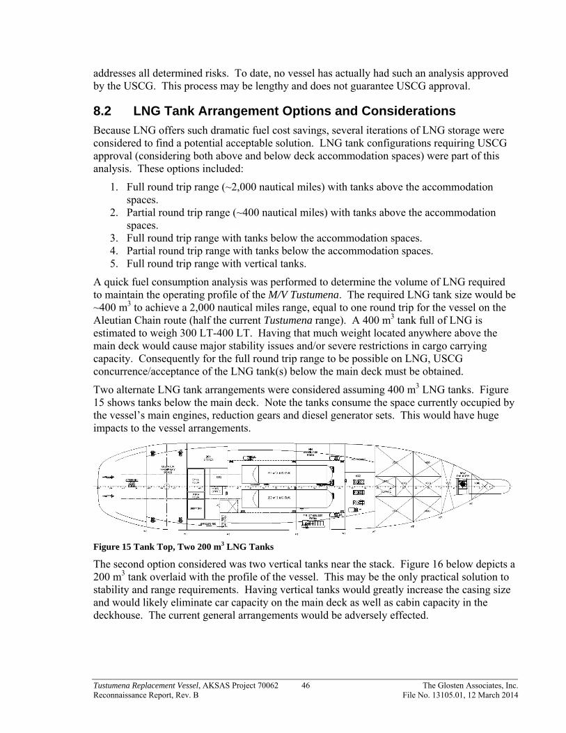
Tustumena Replacement Vessel, AKSAS Project 70062 46 The Glosten Associates, Inc. Reconnaissance Report, Rev. B File No. 13105.01, 12 March 2014
addresses all determined risks. To date, no vessel has actually had such an analysis approved by the USCG. This process may be lengthy and does not guarantee USCG approval.
8.2 LNG Tank Arrangement Options and Considerations
Because LNG offers such dramatic fuel cost savings, several iterations of LNG storage were considered to find a potential acceptable solution. LNG tank configurations requiring USCG approval (considering both above and below deck accommodation spaces) were part of this analysis. These options included:
1. Full round trip range (~2,000 nautical miles) with tanks above the accommodation spaces.
2. Partial round trip range (~400 nautical miles) with tanks above the accommodation spaces.
3. Full round trip range with tanks below the accommodation spaces. 4. Partial round trip range with tanks below the accommodation spaces. 5. Full round trip range with vertical tanks.
A quick fuel consumption analysis was performed to determine the volume of LNG required to maintain the operating profile of the M/V Tustumena. The required LNG tank size would be ~400 m3 to achieve a 2,000 nautical miles range, equal to one round trip for the vessel on the Aleutian Chain route (half the current Tustumena range). A 400 m3 tank full of LNG is estimated to weigh 300 LT-400 LT. Having that much weight located anywhere above the main deck would cause major stability issues and/or severe restrictions in cargo carrying capacity. Consequently for the full round trip range to be possible on LNG, USCG concurrence/acceptance of the LNG tank(s) below the main deck must be obtained.
Two alternate LNG tank arrangements were considered assuming 400 m3 LNG tanks. Figure 15 shows tanks below the main deck. Note the tanks consume the space currently occupied by the vessel’s main engines, reduction gears and diesel generator sets. This would have huge impacts to the vessel arrangements.
Figure 15 Tank Top, Two 200 m3 LNG Tanks
The second option considered was two vertical tanks near the stack. Figure 16 below depicts a 200 m3 tank overlaid with the profile of the vessel. This may be the only practical solution to stability and range requirements. Having vertical tanks would greatly increase the casing size and would likely eliminate car capacity on the main deck as well as cabin capacity in the deckhouse. The current general arrangements would be adversely effected.

Tustumena Replacement Vessel, AKSAS Project 70062 47 The Glosten Associates, Inc. Reconnaissance Report, Rev. B File No. 13105.01, 12 March 2014
Figure 16 Profile, Two 200 m3 LNG Tanks
Considering USCG approval for below deck LNG tanks is not assured, consideration was given to reducing the vessel range from 2,000 nm to 400 nm (enough to fuel the vessel from Homer to Kodiak and back) resulting in a smaller LNG storage tank. This reduced the size of LNG tank to ~100 m3. Given the expected deadweight and stability limitations of the new vessel, this option is the only practical solution if the LNG tank(s) need to be located above the accommodation spaces. A sketch of the LNG tank located on the solarium can be seen in Figure 17 below. This solution would result in relocating or deleting the solarium, relocating the lifesaving equipment and consequently result in major arrangement changes.
Figure 17 Solarium Deck 100 m3 LNG Tank
A possible location for a 100 m3 LNG tank below the main deck is shown in Figure 18. Note significant arrangement and structural changes are still required for fitting such a tank into the existing vessel design.
Figure 18 Tank Top 100 m3 LNG Tank

Tustumena Replacement Vessel, AKSAS Project 70062 48 The Glosten Associates, Inc. Reconnaissance Report, Rev. B File No. 13105.01, 12 March 2014
8.3 Conclusion
The use of LNG to fuel the new vessel has the potential to save 25% over diesel fuel when life cycle costs are considered. An LNG fueled ship and a diesel fueled ship have significantly different requirements for fuel storage and bunkering, and consequently different design solutions. The impacts to vessel arrangements and stability are significant and the resulting vessel design is greatly changed by this decision. For LNG to be a viable option, we recommend:
More investigation into the USCG risk analysis process including actual discussions with the USCG.
Development of an accurate timeline for USCG review and approval through vessel design and construction.
Development of a separate LNG specific concept design to properly maximize the vessel capabilities and minimize needed future arrangement changes.

Tustumena Replacement Vessel, AKSAS Project 70062 49 The Glosten Associates, Inc. Reconnaissance Report, Rev. B File No. 13105.01, 12 March 2014
Section 9 Propulsion Study
9.1 Introduction
Based on the Tustumena Replacement Vessel Propulsion Study that follows, we recommend a twin screw propulsion system consisting of two medium or high speed diesel engines directly-coupled to controllable pitch propellers (CPP) via reduction gears. We recommend an electrically driven, tunnel bow thruster powered by a ships service electrical plant consisting of three diesel generators. This option (Option 1) was selected due to its simplicity, high reliability, and vessel maneuverability. It is also the standard propulsion system used on most existing AMHS vessels. Other options considered, but not recommended are:
Option 1a. This is Option 1 with fixed pitch propellers and was not recommended due to vessel maneuverability and feedback from AMHS crew requesting CPPs.
Option 2. Option 1 with dual fuel engines. Even though the fuel cost savings is substantial, the USCG regulatory issues concerning LNG fuel tank arrangements will greatly influence the vessel’s arrangements. The USCG does not allow LNG fuel tanks to be installed below passenger accommodations without first conducting a risk assessment. This process may be lengthy and does not guarantee USCG approval. It should also be noted that future LNG prices are highly speculative and may not always be cheaper than diesel. The additional complexity of an LNG fuel system also contributed to our recommendation.
Option 3. Diesel Electric with fixed pitch propellers. This is an integrated alternating current (AC) diesel electric propulsion system with four diesel generator sets installed with three being required to maintain cruising speed and ship service electrical load. This option was not recommended due to the higher capital cost of equipment, increased maintenance cost, and lower system efficiency resulting in higher fuel costs. Due to the power differential between the anticipated ship service/hotel load and the propulsion load, a diesel electric system is not advantageous.
Option 4. Option 1 with diesel driven bow thruster. This option was not recommended due to the increased installation and maintenance costs associated with an additional diesel engine. There is also no redundancy in the event of a bow thruster engine failure. A diesel-driven thruster will also have a slower response time than an electrically-driven thruster.
Option 5. Option 1 with shaft generators driven off the main reduction gear. This option was not recommended due to the increased system complexity, capital cost, and maintainability.
9.2 Purpose
The purpose of this study is to determine the propulsion system configuration best suited to fulfill the mission requirements for the M/V Tustumena Replacement Vessel. This study presents the methodology considered to identify propulsion system configurations suitable for this vessel and the selection process.

Tustumena Replacement Vessel, AKSAS Project 70062 50 The Glosten Associates, Inc. Reconnaissance Report, Rev. B File No. 13105.01, 12 March 2014
9.3 Procedure
This study examined five basic propulsion configurations for the Tustumena Replacement Vessel for Alaska Marine Highway System (AMHS). All propulsion configurations were evaluated based on selection criteria. A 30-year life cycle cost analysis was performed for each option. Option 1 was considered baseline and all values represent variations in relation to this option. Positive numbers represent better performance and less cost while negative numbers represent inferior performance and higher cost.
9.4 Given and Assumed Parameters
Operational Profile
The operational profile of the vessel was determined based on information gathered from AMHS on the M/V Tustumena route and vehicle information. The operational profile was used for developing load profiles when evaluating the life cycle cost analysis. Operating time spent on each day was gathered from M/V Kennicott propulsion study and was extrapolated to maintain the Southwest route exclusively. Calculated values and assumed parameters are summarized in Table 11.
Table 11 Operational Profile
Mission Cruising Maneuvering Dockside Annual
Speed (knots) 15 5 0
Operating Time (days) 251 16.8 67 335
Power Requirements
The estimated powering requirements for this study were determined from various methods of calculation. Propulsion power was determined based on estimated speed vs. power curves developed from the preliminary lines plan. Ship service and vehicle elevator loads were parametrically scaled from the current M/V Tustumena design.
The design speed to maintain schedule was determined to be 15 knots at Sea State 4. This yields a required minimum power of 6,000 HP total (3,000 HP/shaft) for the main propulsion engines and can be seen in Figure 19.

Tustumena Replacement Vessel, AKSAS Project 70062 51 The Glosten Associates, Inc. Reconnaissance Report, Rev. B File No. 13105.01, 12 March 2014
Figure 19 Estimated Propulsion Power vs. Speed for Sea State 4
The bow thruster sizing was based on the bow thruster installation on the M/V Kennicott, which is well regarded by the AMHS operators. Scaling the thrust for reduced windage area of the Tustumena Replacement Vessel yields a required thrust of 22,000 lbs. This is the minimum thrust required and is comparable to the M/V Columbia (25,300 lbs). Calculations verify this thruster should allow vessel maneuvering in winds up to 30 knots.
A summary of the developed power requirements can be seen in Table 12 below. The bow thruster accounted for 1150 ekW and was only utilized during maneuvering. The vehicle elevator accounted for 300 ekW and was only utilized dockside. A ship service electrical load of 500 ekW was conservatively accounted for in all power profiles.
Table 12 Estimated Power Requirements
Transit Maneuvering Dockside
Propulsion Power (hp) 6,000 1,200 0
Shaft Power (hp) 6,000 1,200 0
Average Electric Load (ekW) 500 1,650 800
SS Load (ekW) 500 500 500
Bow Thruster (ekW) 0 1150 0
Elevator (ekW) 0 0 300
Speed (kts)
Pro
puls
ion
Pow
er
(BH
P)
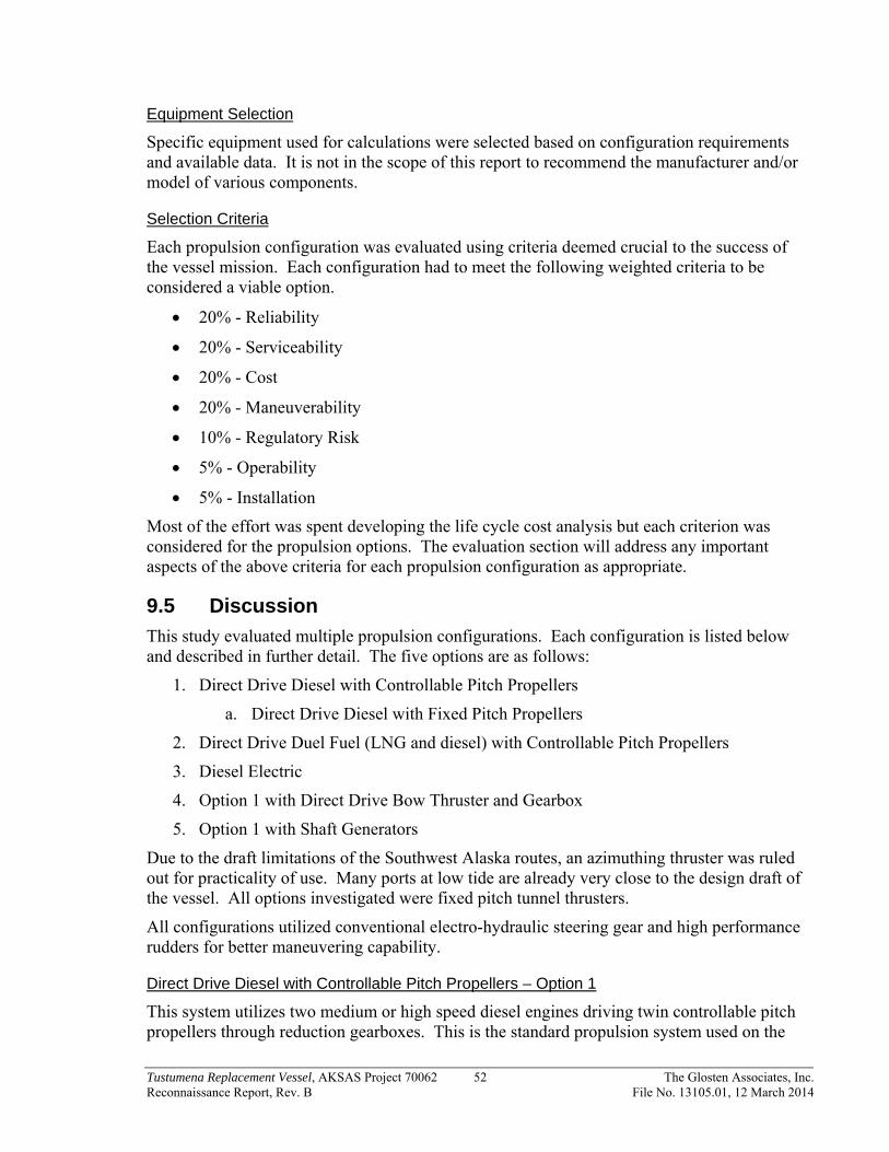
Tustumena Replacement Vessel, AKSAS Project 70062 52 The Glosten Associates, Inc. Reconnaissance Report, Rev. B File No. 13105.01, 12 March 2014
Equipment Selection
Specific equipment used for calculations were selected based on configuration requirements and available data. It is not in the scope of this report to recommend the manufacturer and/or model of various components.
Selection Criteria
Each propulsion configuration was evaluated using criteria deemed crucial to the success of the vessel mission. Each configuration had to meet the following weighted criteria to be considered a viable option.
20% - Reliability
20% - Serviceability
20% - Cost
20% - Maneuverability
10% - Regulatory Risk
5% - Operability
5% - Installation
Most of the effort was spent developing the life cycle cost analysis but each criterion was considered for the propulsion options. The evaluation section will address any important aspects of the above criteria for each propulsion configuration as appropriate.
9.5 Discussion
This study evaluated multiple propulsion configurations. Each configuration is listed below and described in further detail. The five options are as follows:
1. Direct Drive Diesel with Controllable Pitch Propellers
a. Direct Drive Diesel with Fixed Pitch Propellers
2. Direct Drive Duel Fuel (LNG and diesel) with Controllable Pitch Propellers
3. Diesel Electric
4. Option 1 with Direct Drive Bow Thruster and Gearbox
5. Option 1 with Shaft Generators
Due to the draft limitations of the Southwest Alaska routes, an azimuthing thruster was ruled out for practicality of use. Many ports at low tide are already very close to the design draft of the vessel. All options investigated were fixed pitch tunnel thrusters.
All configurations utilized conventional electro-hydraulic steering gear and high performance rudders for better maneuvering capability.
Direct Drive Diesel with Controllable Pitch Propellers – Option 1
This system utilizes two medium or high speed diesel engines driving twin controllable pitch propellers through reduction gearboxes. This is the standard propulsion system used on the

Tustumena Replacement Vessel, AKSAS Project 70062 53 The Glosten Associates, Inc. Reconnaissance Report, Rev. B File No. 13105.01, 12 March 2014
AMHS main line vessels. The two diesel engines, each rated for a minimum 3,500 BHP are installed and turn a dedicated shaft and propeller. Both port and starboard shafts are clutched on the input side of the gearbox.
The bow thruster consists of a single variable frequency drive (VFD) electric motor powered from the vessel’s ship service electrical plant. The drive motor is installed vertically, directly above the tunnel thruster.
Separate ship service diesel generators (three at 700 ekW each) and switchboards for electrical power generation are installed. Power for normal hotel loads will be supplied by one generator. A split bus segregates the bow thruster and vehicle elevator loads from the regular ship service switchboard. A bus tie is used for redundancy of generators as well as equal load sharing during generator life.
Figure 20 Direct Drive Diesel with Controllable Pitch Propellers - Option 1 Configuration
A variation of this option is to use fixed pitch propellers within the same propulsion configuration (Option 1a). This is the current propulsion system concept used on the M/V Tustumena. The use of fixed pitch propellers in place of controllable pitch propellers will slightly benefit fuel savings with a gain of about 4% efficiency, but greatly affects maneuverability, capital cost, and maintenance. The benefits and drawbacks will be discussed in the Evaluation Section.
Direct Drive Duel Fuel with Controllable Pitch Propellers – Option 2
This system utilizes two medium or high speed duel fuel (diesel and natural gas) engines driving twin controllable pitch propellers through reduction gearboxes. The two engines, each rated for a minimum 3,500 BHP are installed and turn a dedicated shaft and propeller. Both port and starboard shafts are clutched on the input side of the gearbox.
The duel fuel engines do not inherently change the layout of the propulsion system but the liquefied natural gas (LNG) storage greatly affects overall vessel arrangements, required equipment, and tankage. A large class C vacuum tank will be required for storage of LNG as well as a double block and bleed valve enclosure in the engine room. See Section 8 of this report for discussion of LNG storage tank issues.

Tustumena Replacement Vessel, AKSAS Project 70062 54 The Glosten Associates, Inc. Reconnaissance Report, Rev. B File No. 13105.01, 12 March 2014
As with Option 1, the bow thruster consists of a single VFD electric motor to power the thruster which is powered from the vessel’s electrical plant. It is installed vertically directly over the tunnel thruster.
As with Option 1, separate ship service diesel generators (three at 700 kW each) and switchboards for electrical power generation are installed. It is possible to configure the generators to run on natural gas as well but options are limited for small generation plant duel fuel engines. A split bus segregates the bow thruster and vehicle elevator from the ship service switchboard. A bus tie is used for redundancy of generators as well as equal load sharing during generator life.
Figure 21 Direct Drive Duel Fuel with Controllable Pitch Propellers - Option 2 Configuration
Diesel Electric with Fixed Pitch Propellers – Option 3
This is an integrated AC diesel electric propulsion system. Four diesel generator sets are employed with three being required to maintain the 6000 BHP propulsion power requirement. This system is arranged as an integrated electric plant – i.e., the ship service and hotel electric load is supplied by the integrated plant, eliminating the need for a separate diesel generator to supply the ship’s non-propulsion electric load.
This system takes advantage of modern AC/AC drive technology which is relatively efficient, quiet, and light weight compared to older DC propulsion technologies, but still requires additional electrical equipment for speed control and harmonic attenuation. The propulsion motor speed and torque relationship is similar to a DC motor and is suitable for driving a fixed pitch propeller.
Power factors may range from 0.80 to 0.90. The generators supply a main propulsion switchboard. Each propulsion motor is a dual winding asynchronous type rated at approximately 2250 kW (3,000 BHP) minimum at 180 RPM. The dual winding motors offer some redundancy. Each motor drives a conventional fixed pitch propeller.
As with Option 1, the bow thruster consists of a single VFD electric motor to power the thruster which is run off the vessel’s electrical plant. It is installed vertically directly over the tunnel thruster.

Tustumena Replacement Vessel, AKSAS Project 70062 55 The Glosten Associates, Inc. Reconnaissance Report, Rev. B File No. 13105.01, 12 March 2014
Figure 22 Diesel Electric with Fixed Pitch Propellers - Option 3 Configuration
Direct Drive Bow Thruster and Gearbox – Option 4
This propulsion configuration is similar to the baseline Option 1, but modified to include a diesel driven bow thruster (similar to M/V Columbia).
The thruster utilizes a dedicated diesel engine directly driving the thruster through a 90 degree offset reduction gearbox. The bow thruster diesel engine will be rated for a minimum 1,600 BHP and will be installed in the bow thruster room.
Figure 23 Direct Drive Bow Thruster and Gearbox - Option 4 Configuration
Included Shaft Generators – Option 5
This configuration is similar to the baseline Option 1, but modified to include shaft generators, similar to the M/V Kennicott.
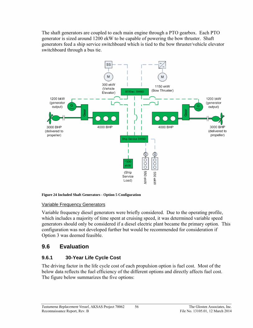
Tustumena Replacement Vessel, AKSAS Project 70062 56 The Glosten Associates, Inc. Reconnaissance Report, Rev. B File No. 13105.01, 12 March 2014
The shaft generators are coupled to each main engine through a PTO gearbox. Each PTO generator is sized around 1200 ekW to be capable of powering the bow thruster. Shaft generators feed a ship service switchboard which is tied to the bow thruster/vehicle elevator switchboard through a bus tie.
Figure 24 Included Shaft Generators - Option 5 Configuration
Variable Frequency Generators
Variable frequency diesel generators were briefly considered. Due to the operating profile, which includes a majority of time spent at cruising speed, it was determined variable speed generators should only be considered if a diesel electric plant became the primary option. This configuration was not developed further but would be recommended for consideration if Option 3 was deemed feasible.
9.6 Evaluation
9.6.1 30-Year Life Cycle Cost
The driving factor in the life cycle cost of each propulsion option is fuel cost. Most of the below data reflects the fuel efficiency of the different options and directly affects fuel cost. The figure below summarizes the five options:
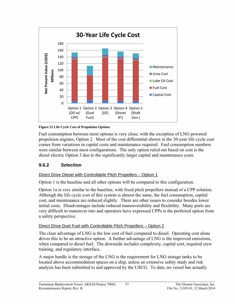
Tustumena Replacement Vessel, AKSAS Project 70062 57 The Glosten Associates, Inc. Reconnaissance Report, Rev. B File No. 13105.01, 12 March 2014
Figure 25 Life Cycle Cost of Propulsion Options
Fuel consumption between most options is very close, with the exception of LNG powered propulsion engines, Option 2. Most of the cost differential shown in the 30-year life cycle cost comes from variations in capital costs and maintenance required. Fuel consumption numbers were similar between most configurations. The only option ruled out based on cost is the diesel electric Option 3 due to the significantly larger capital and maintenance costs.
9.6.2 Selection
Direct Drive Diesel with Controllable Pitch Propellers – Option 1
Option 1 is the baseline and all other options will be compared to this configuration.
Option 1a is very similar to the baseline, with fixed pitch propellers instead of a CPP solution. Although the life cycle cost of this system is almost the same, the fuel consumption, capital cost, and maintenance are reduced slightly. There are other issues to consider besides lower initial costs. Disadvantages include reduced maneuverability and flexibility. Many ports are very difficult to maneuver into and operators have expressed CPPs is the preferred option from a safety perspective.
Direct Drive Duel Fuel with Controllable Pitch Propellers – Option 2
The clear advantage of LNG is the low cost of fuel compared to diesel. Operating cost alone drives this to be an attractive option. A further advantage of LNG is the improved emissions, when compared to diesel fuel. The downside includes complexity, capital cost, required crew training, and regulatory interface.
A major hurdle is the storage of the LNG is the requirement for LNG storage tanks to be located above accommodation spaces on a ship, unless an extensive safety study and risk analysis has been submitted to and approved by the USCG. To date, no vessel has actually
0
20
40
60
80
100
120
140
160
180
Option 1(DD w/CPP)
Option 2(DuelFuel)
Option 3(DE)
Option 4(DieselBT)
Option 5(ShaftGen.)
Net Present Value (USD
$)
Millions
30‐Year Life Cycle Cost
Maintenance
Urea Cost
Lube Oil Cost
Fuel Cost
Capital Cost

Tustumena Replacement Vessel, AKSAS Project 70062 58 The Glosten Associates, Inc. Reconnaissance Report, Rev. B File No. 13105.01, 12 March 2014
had such an analysis approved by the USCG. Section 8 details further analysis and explanation of a LNG fueled vessel.
Diesel Electric - Option 3
An integrated diesel-electric propulsion installation can provide many benefits for certain vessel types. For vessels that spend large portions of time maneuvering, holding station, and/or with several large electrical loads (winches, cranes, thrusters, etc.) diesel-electric propulsion can provide a level of flexibility that allows operators to optimize the number of engines running to meet their operating requirements and reduce fuel consumption. Another potential benefit to the diesel-electric propulsion is increased redundancy since there are several generators connected to a common bus that can provide power to the propulsion drives. The electric motors and drives typically have lower failure rates and shorter repair times than diesel engines, and could lead to higher vessel availability.
However, this added flexibility comes with significantly increased capital and maintenance costs. For vessels that spend long periods of time cruising, it is often found that diesel electric propulsion results in higher fuel expenses when compared to directly driven diesel-mechanical propulsion. This is due to the additional losses in the electrical components (generators, transformers, drives, and motors) that are not present with direct drive propulsion.
Currently AMHS does not have any diesel electric propulsion systems in their fleet and would require specific operator training and procedures for this vessel. If higher voltages (> 1000V) were used, additional specialized training and safety requirements would apply to this vessel.
The anticipated operating profile for this vessel suggests that this vessel will not benefit from the added flexibility offered by a diesel-electric propulsion plant since it spends a vast majority of time in transit at constant speed. Due to the higher capital costs and higher operating expenses, diesel-electric propulsion is not recommended for this vessel.
Diesel Bow Thruster with Reduction Gear - Option 4
The main advantage of this system lies in the reduced electrical plant size, reducing the size and number of auxiliary generators. The large variation in relative electrical loads makes this vessel an ideal candidate for a directly driven bow thruster. Currently the large load of the bow thruster is driving the size of the electrical plant. Including the bow thruster in the electrical load creates larger generators and a minimum of three generators for redundancy. Removing the need for the bow thruster load in the electrical plant allows for a much more efficient design and smaller space requirements in the Auxiliary Machinery Room.
Disadvantages include increased ventilation and pipe routing to the bow thruster compartment along with increased maintenance. The initial bow thruster response time can also be a problem if the engine is not kept running prior to need of bow thruster maneuvering (i.e. sudden availability of the bow thruster is dependent on starting the diesel engine). The bow thruster room is a difficult location to maintain a diesel engine.
Shaft Generators - Option 5
Shaft generators are a great way to increase fuel efficiency of the entire propulsion system, as large engines often are more fuel efficient than smaller engines. This configuration also reduces the need for a third auxiliary generator. The savings in life cycle cost indicates this
Tustumena Replacement Vessel, AKSAS Project 70062 59 The Glosten Associates, Inc. Reconnaissance Report, Rev. B File No. 13105.01, 12 March 2014
could be a good option to pursue further, but increased system complexity and maintainability are major drawbacks. Only one other vessel in the fleet has shaft generators and crews may need to be trained on the new system.
9.7 Conclusion
Based on the results of this study, the propulsion configuration best suited for the proposed operations is Option 1, the Baseline Option. Directly driven diesel engines with controllable pitch propellers allows the most maneuverability, flexibility and reliability. Figure 26 depicts the weighted scores for each option in relation to Option 1. All options weighted scores are overall negative (inferior performance/higher cost) based on the criteria selected.
Figure 26 Weighted Scoring Compared to Option 1
‐10.00%
‐8.00%
‐6.00%
‐4.00%
‐2.00%
0.00%
2.00%
4.00%
6.00%
1a 2 3 4 5
Inferior Perform
ance/
Higher Cost
Propulsion Option
Weighted Scores
Installation
Operability
Regulatory Risk
Maneuverability
Cost
Serviceability
Reliability
Better Perform
ance/
Lower Cost

Tustumena Replacement Vessel, AKSAS Project 70062 60 The Glosten Associates, Inc. Reconnaissance Report, Rev. B File No. 13105.01, 12 March 2014
The table below summarizes detailed scores and weighting of each criteria evaluated.
Table 13 Scoring Matrix
Reliability
Serviceability
Cost
Maneuverability
Regulatory Risk
Operability
Installation
WeightedScore Rank Weighting Factor: 20% 20% 20% 20% 10% 5% 5%
Option Propulsion Description
1 Direct Drive Diesel with CPP 0% 0% 0% 0% 0% 0% 0% 0% 1
1a Direct Drive Diesel with FP 5% 5% 5% ‐25% 0% 5% 5% ‐1.5% 2
2 Duel Fuel 0% ‐15% 26% 0% ‐30% ‐15% ‐25% ‐2.8% 4
3 Diesel Electric w/ Fixed Pitch ‐10% ‐15% ‐8% 10% 0% ‐10% ‐20% ‐6.1% 6
4 Direct Drive BT and Gearbox ‐5% ‐5% ‐2% 0% 0% 0% ‐5% ‐2.6% 3
5 Shaft Generators ‐10% ‐10% 2% 0% 0% ‐10% ‐10% ‐4.6% 5
For Option 2 to be viable, we recommend more investigation into the USCG risk analysis process and development of an accurate timeline for USCG involvement through vessel construction.

Tustumena Replacement Vessel, AKSAS Project 70062 61 The Glosten Associates, Inc. Reconnaissance Report, Rev. B File No. 13105.01, 12 March 2014
Section 10 Weight and Stability
10.1 Weight and Center of Gravity Estimate
10.1.1 Summary
At this early concept stage, the arrangements are updated regularly based on feedback from the crew, changes made to comply with regulatory requirements, owner preferences, and various other considerations. The Tustumena Replacement Vessel is being designed around the central concept of increasing upon the Tustumena's baseline service capacity, and thus revenue, by providing more space for vehicles and passengers.. Thus, developing a weight estimate based on parametric data from other vessels in the AMHS fleet is a valid approach at this stage of design.
The cubic number, based upon length at the water line, beam at the waterline, and depth, was calculated based on a LWL of 309.5 feet, BWL of 65 feet, and Depth of 23 feet. Design, shipyard, and service life margins were also calculated. The results of these calculations are summarized in Table 14.
Table 14 Weight estimate summary
Item Weight (LT)
VCG (ft)
LCG (ft)
Lightship 3,604 26.8 156.4
Tankage 503.0 6.7 165.2
Cargo 465.0 31.8 153.8
Subtotal 4,572 25.1 157.0
Margin 445.0 36.2 200.0
Total 5,017 26.1 160.9
The estimated design draft at this lightship is 14.5 feet. With the service margin, the estimated draft increases to 15.5 feet. These drafts satisfy the requirements as defined in Section 2.
10.1.2 Lightship
A regression analysis of lightship weight versus cubic number was developed using the latest lightship weights of eight (8) existing AMHS vessels: Aurora, Columbia, Kennicott, LeConte, Malaspina, Matanuska, Taku, and Tustumena. This plot excluded the Fairweather, Chenega, and Lituya. Figure 27 shows the vessel data used in the analysis and the regression line utilized to estimate the lightship weight of the Tustumena Replacement Vessel.

Tustumena Replacement Vessel, AKSAS Project 70062 62 The Glosten Associates, Inc. Reconnaissance Report, Rev. B File No. 13105.01, 12 March 2014
Figure 27 Lightship weight regression
The cubic number of the Tustumena Replacement Vessel is CN=4,627. The mean lightship weight corresponding to this cubic number is 3,414.5 long tons. A design margin was added to the mean weight by assuming a normal distribution with a 0.95 confidence interval (i.e. 95% probability that the actual lightship weight does not exceed the estimation). At this stage of the design, a high confidence level is recommended so that weight is not underestimated. The estimated lightship weight inclusive of design margin for the Tustumena Replacement Vessel is 3,604 long tons.
10.1.3 Margins
Table 15 reflects the allocation and utilization of margins in the weight estimate. The design margin is assumed to be included in the 0.95 confidence interval for the lightship weight estimate (see 10.1.2). The shipyard margin is the allowance we have assumed for the shipyard in developing and constructing the vessel. The shipyard margin weight was calculated to be 2.96% of lightship weight based on Glosten historical parametrics.
The service life margin is supplied to ensure that the vessel remains viable to the end of its service life. The growth rate of vessel lightship weight was compiled for the existing AMHS vessels Aurora, LeConte, Malaspina, Taku, and Tustumena. The average growth rate, in long tons per year (calculated to be 5.29 LT/yr), was multiplied by a service life of 64 years to arrive at the service life margin weight shown below. A 0.5 foot rise in vertical center of gravity was included for both the shipyard and service margins.
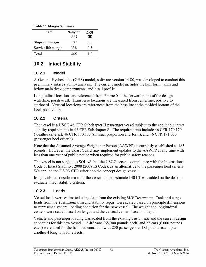
Tustumena Replacement Vessel, AKSAS Project 70062 63 The Glosten Associates, Inc. Reconnaissance Report, Rev. B File No. 13105.01, 12 March 2014
Table 15 Margin Summary
Item Weight (LT)
KG (ft)
Shipyard margin 107 0.5
Service life margin 338 0.5
Total 445 1.0
10.2 Intact Stability
10.2.1 Model
A General Hydrostatics (GHS) model, software version 14.00, was developed to conduct this preliminary intact stability analysis. The current model includes the hull form, tanks and below main deck compartments, and a sail profile.
Longitudinal locations are referenced from Frame 0 at the forward point of the design waterline, positive aft. Transverse locations are measured from centerline, positive to starboard. Vertical locations are referenced from the baseline at the molded bottom of the keel, positive up.
10.2.2 Criteria
The vessel is a USCG 46 CFR Subchapter H passenger vessel subject to the applicable intact stability requirements in 46 CFR Subchapter S. The requirements include 46 CFR 170.170 (weather criteria), 46 CFR 170.173 (unusual proportion and form), and 46 CFR 171.050 (passenger heel criteria).
Note that the Assumed Average Weight per Person (AAWPP) is currently established as 185 pounds. However, the Coast Guard may implement updates to the AAWPP at any time with less than one year of public notice when required for public safety reasons.
The vessel is not subject to SOLAS, but the USCG accepts compliance with the International Code of Intact Stability, 2008 (2008 IS Code), as an alternative to the passenger heel criteria. We applied the USCG CFR criteria to the concept design vessel.
Icing is also a consideration for the vessel and an estimated 40 LT was added on the deck to evaluate intact stability criteria.
10.2.3 Loads
Vessel loads were estimated using data from the existing M/V Tustumena. Tank and cargo loads from the Tustumena trim and stability report were scaled based on principle dimensions to represent a general loading condition for the new vessel. The weight and longitudinal centers were scaled based on length and the vertical centers based on depth.
Vehicle and passenger loading was scaled from the existing Tustumena and the current design capacities for this new vessel. 12 40' vans (68,000 pounds each) and 27 cars (6,000 pounds each) were used for the full load condition with 250 passengers at 185 pounds each, plus another 4 long tons for effects.

Tustumena Replacement Vessel, AKSAS Project 70062 64 The Glosten Associates, Inc. Reconnaissance Report, Rev. B File No. 13105.01, 12 March 2014
10.2.4 Preliminary Results
The current vessel model passes the intact stability criteria with large margins for the representative sample loading conditions. We checked a full load departure, 50% burnout, and 10% arrival conditions.
10.2.5 Future Analysis
The following analysis will be completed during the next design cycle.
Establish vehicle loading scenarios
Define maximum desired and minimum fuel tank capacities for well-defined loading conditions.
Define tankage and free surface corrections
Define downflooding points
Apply ice loading conditions
10.3 Subdivision and Damage Stability
10.3.1 Subdivision
46 CFR 171.060 states that a vessel of this size and service must be shown to satisfy the requirements for Type I subdivision. The calculations prescribe the maximum distance between main transverse watertight bulkheads as a relationship between floodable length and the factor of subdivision.
10.3.2 USCG Deterministic Method
46 CFR 171.080 details the deterministic criteria for damage stability standards for vessels with Type I subdivision.
10.3.3 SOLAS Probabilistic Method
While the vessel is not a SOLAS passenger vessel, it is classed by the American Bureau of Shipping (ABS). ABS Steel Vessel Rules (ABS SVR Part 3, Chapter 3.3 and Part 5C, Chapter 7, Section 3) state that SOLAS probabilistic stability regulations II-1/4 through 8-1 are applied for damage stability.
10.3.4 Compartments
Main transverse watertight bulkheads (MTWB) are located at Frames 8, 20, 31, 46, 58, 77, 104, 120, and 136. These bulkhead locations were selected to meet the subdivision requirements above. A floodable length calculation using a 6" margin line was used. 6" is more than the minimum required but was used because the vessel will perform better with water on deck if there is more freeboard after damage. The final bulkhead spacing will be adjusted to suit the more detailed Damage Stability calculations as the design progresses.
10.3.5 Future Analysis
The following analysis will be completed during the next design cycle.

Tustumena Replacement Vessel, AKSAS Project 70062 65 The Glosten Associates, Inc. Reconnaissance Report, Rev. B File No. 13105.01, 12 March 2014
Establish vehicle loading scenarios
Define tankage and free surface corrections
Define critical points
Perform USCG deterministic damage stability calculations
Perform SOLAS probabilistic damage stability calculations
10.4 Water-on-Deck Criteria
10.4.1 IMO and Stockholm Agreement Methodology
The IMO Panel of Experts developed recommendations for water-on-deck provisions after the Estonia disaster in 1994. The US is not a signatory to the IMO water-on-deck criteria.
Another convention was held in Stockholm and in 1996 the Stockholm Agreement was passed that imposes water-on-deck damaged stability conditions similar to the IMO.
Both water-on-deck criteria allow for demonstrating compliance through model testing and a number of passenger ships use this method because it is less conservative.
Water-on-deck calculations will be performed during future design work to check compliance with the criteria and evaluate if any changes can be made to achieve compliance. Water-on-deck is currently not a required criterion, but evaluation is warranted since the rules may be applied in the future on the subject vessel.

Tustumena Replacement Vessel, AKSAS Project 70062 66 The Glosten Associates, Inc. Reconnaissance Report, Rev. B File No. 13105.01, 12 March 2014
Section 11 Cost Estimate
11.1 Summary
Vessel shipyard and program cost estimates have been developed to establish a project cost. All estimates are in 2014 dollars (or have been adjusted accordingly).
In support of AMHS in developing these estimates for the Tustumena Replacement Vessel, it is important to understand the various program and construction cost elements. Both are significant drivers to identifying and establishing a total program cost.
11.1.1 Vessel Shipyard Construction Cost
Glosten commissioned two independent vessel shipyard construction cost estimates from two different parties. The two cost estimators used different methods for estimating capital costs: a Volumetric Method, and a Ship Work Breakdown Structure (SWBS) method.
The vessel capital cost estimates are shown in Table 16 and are within 8% of each other. There are common cost allowances between the two methods, including owner contingency of 10% to cover shipyard costs as the design and cost estimate are refined. This contingency will be adjusted going forward as the design and cost estimates mature.
Table 16 Shipyard Construction Cost Estimate Summary (2014 Dollars)
Cost Basis Volumetric method
SWBS Method (West Coast)
SWBS Method (Gulf Coast)
Estimated capital cost $173,000,000 $169,000,000 $160,000,000
Owner contingency (10%)
$17,000,000 $17,000,000 $16,000,000
Total $190,000,000 $186,000,000 $176,000,000
11.1.2 Program Costs
Program costs are other items not directly related to the shipyard constructing the vessel, but are required to execute the project.
Table 17 reflects program costs and is composed of the following elements:
Program Contingency of 10% to cover changes in program and construction costs.
ICAP of 4.79% (Indirect Cost Recovery Plan).
Loose outfitting and equipage to cover outfitting of the vessel not supplied by the shipyard.
Construction Support of 10%. This is for the on-site team and all construction support including consultants, travel, and per diem

Tustumena Replacement Vessel, AKSAS Project 70062 67 The Glosten Associates, Inc. Reconnaissance Report, Rev. B File No. 13105.01, 12 March 2014
Table 17 Program Cost Basis (2014 Dollars)
Item Estimated Cost
Program Contingency (10%) $19,000,000
ICAP (4.79%) $9,100,000
Loose Outfitting and equippage $4,000,000
Construction Support (10%) $19,000,000
Total Program Cost $51,100,000
11.1.3 Total Estimated Project Cost
The total estimated project cost is the summation of all the shipyard construction costs and program costs.
Based upon the preceding information the estimated project cost is:
Table 18 Total Estimate Cost Summary (2014 dollars)
Volumetric Method SWBS Method (West Coast)
SWBS Method (Gulf Coast)
$241,100,000 $237,100,000 $227,100,000
11.2 Volumetric-Based Estimate
One cost estimate is based on parametric data from historical costs for AMHS vessels. The volume of spaces is calculated and the costs divided into six major sections: hull structure, superstructure, accommodation outfitting, machinery, trials and delivery, and advanced safety features (SOLAS or Ocean class). The detailed line item costs are shown in Appendix G, along with comparison costs to the M/V Kennicott and M/V Tustumena. It should be noted that the costs in Appendix G, calculated in 2012 dollars, have been adjusted to 2014 dollars for the purposes of this report.
11.3 Detailed SWBS Estimate
The second cost estimate took the more traditional approach and assigned units, quantities, unit labor, unit materials, and unit subcontracts to specific work items to develop the base capital cost. Work items include major SWBS category items for engineering and yard services, hull structure, propulsion, electrical plant, command and surveillance, general machinery, outfit and furnishings, and post construction support.
The steel weight was based on the 1st generation, 350’ long, Alaska Class Ferry (ACF), assuming the Tustumena Replacement Vessel would be about 10% lighter. The 350’ ACF weight estimate was also used for high level detail weight estimates.

Tustumena Replacement Vessel, AKSAS Project 70062 68 The Glosten Associates, Inc. Reconnaissance Report, Rev. B File No. 13105.01, 12 March 2014
While the Tustumena Replacement Vessel is not a SOLAS vessel, some aspects of the vessel will be built to SOLAS standards for safety of the crew and passengers in the Alaska operating environment. These include fire dampers, insulation, and lifesaving equipment.
Due to the importance and significant cost of the vehicle elevator, a specific cost for this item was identified and estimated at $15 million. In a similar fashion, the fin stabilizer pair was estimated at $2 million, uninstalled.
A material markup of 15% was also added to the base capital cost.
Labor rates for both the Gulf Coast and Pacific Northwest were also included to provide cost estimates for two geographic locations likely to build the Tustumena Replacement Vessel.

Tustumena Replacement Vessel, AKSAS Project 70062 69 The Glosten Associates, Inc. Reconnaissance Report, Rev. B File No. 13105.01, 12 March 2014
Section 12 Terminal Compatibility
12.1 Introduction
12.1.1 Purpose of Study
The Tustumena Replacement Vessel is intended to operate in conjunction with a unique combination of ports and terminals. The majority of ports in the Tustumena’s area of operation are unimproved piers, characterized by tall vertical faces and fixed height pier decks. However, the Tustumena Replacement Vessel is also intended to operate in conjunction with terminals specially designed for vehicle loading which is characterized by floating or adjustable loading interfaces. Each of these different types of loading facilities has different operating conditions and limitations and a unique spatial arrangement. This study is intended to define the arrangements and operating limitations associated with each terminal interface. Given the large number of terminals and wide spectrum of required data, the analysis has been broken down into the following categories:
1) Fixed Height Vehicle Loading.
Loading of vehicles at fixed height piers is assumed to be completed with the use of a vehicle elevator. The required operating range of the elevator is dependent on the pier geometry (height), maximum tides (high and low), vessel freeboard, and elevator geometry.
2) Vehicle Loading at Adjustable Height Terminals
Loading of vehicles at adjustable terminals is assumed to be completed with the use of the existing terminal ramp. This loading can occur over either the stern or side port door, depending on terminal arrangement. The vessel freeboard must be within the operating range of the adjustable terminals.
3) Passenger Loading (Boarding Ladder)
The vessel design needs to permit passenger loading at both fixed height piers and adjustable height docks.
a) Passenger Loading at Fixed Height Pier
For fixed height piers, it is assumed that the passengers are loaded using passenger accommodation ladders and gangways, as the vehicle elevator will not be rated for walk-on passengers. Like the vehicle elevator, the operating range of the boarding ladder is dependent on the pier geometry (height), maximum tides (high and low), vessel freeboard, and ladder geometry.
b) Passenger Loading at Adjustable Terminals.
For adjustable height docks, passenger loading is assumed to be via the terminal transfer bridge which spans between the terminal and the vessel main deck.
4) Mooring Arrangement
Safe and secure vessel mooring is required at each terminal, particularly since vessel motion is a critical component of vehicle elevator operation. Each terminal

Tustumena Replacement Vessel, AKSAS Project 70062 70 The Glosten Associates, Inc. Reconnaissance Report, Rev. B File No. 13105.01, 12 March 2014
must be examined to determine acceptable vessel/fender interface and mooring line arrangement.
Currently this report does not address “dock side services,” meaning the terminal’s capability to provide support services to the vessel, such as: fuel, potable water, black water discharge, electricity, phone, cable, etc. If the AMHS desires any of these services, this report can be amended with a listing of these capabilities.
12.1.2 Ports of Call
Based on the definition of service area provided, the Tustumena Replacement Vessel needs to be able to load and unload both vehicle and passengers at the following terminals
Akutan (AKU) City of Akutan Bellingham, WA (BEL) Port of Bellingham Chenega Bay (CHB) North Pacific Rim Housing Authority Chignik (CHG) Trident Seafoods Cold Bay (CBY) Aleutian East Borough Cordova (CDV) State of Alaska Dutch Harbor (UNA) City of Unalaska False Pass (FPS) Village of False Pass Homer (HOM) City of Homer Juneau (JNU) State of Alaska Ketchikan (KTN) State of Alaska King Cove (KCV) Aleutians East Borough Kodiak (KOD) City of Kodiak Old Harbor (OLD) City of Old Harbor Ouzinkie (OUZ) City of Ouzinkie Port Lions (ORI) City of Port Lions Sand Point (SDP) City of Sand Point Seldovia (SDV) City of Seldovia Tatitlek (TAT) North Pacific Rim Housing Authority Valdez (VDZ) State of Alaska Whittier (WTR) State of Alaska Yakutat (YAK) City of Yakutat
The condition of AMHS terminals is monitored by Alaska DOT&PF, who also maintains and publishes a document called the 2012 AMHS Shore Facilities Condition Survey Report. This report contains condition information, but also contains a good general description of each terminal and associated piers. The condition survey can be found at http://dot.alaska.gov/project_info/AMHS_Shore_Fac_Report.shtml

Tustumena Replacement Vessel, AKSAS Project 70062 71 The Glosten Associates, Inc. Reconnaissance Report, Rev. B File No. 13105.01, 12 March 2014
For purposes of general familiarity, the following pictures of each terminal are provided:
Akutan Auke Bay
Bellingham Chenega Bay
Chignik Cold Bay
Figure 28 AMHS Terminals

Tustumena Replacement Vessel, AKSAS Project 70062 72 The Glosten Associates, Inc. Reconnaissance Report, Rev. B File No. 13105.01, 12 March 2014
Cordova Dutch Harbor
False Pass Homer
Ketchikan King Cove
Figure 29 AMHS Terminals

Tustumena Replacement Vessel, AKSAS Project 70062 73 The Glosten Associates, Inc. Reconnaissance Report, Rev. B File No. 13105.01, 12 March 2014
Kodiak – Pier I (to be refurbished) Kodiak – Pier II
Old Harbor Ouzinkie
Port Lions (to be replaced) Sand Point
Figure 30 AMHS Terminals

Tustumena Replacement Vessel, AKSAS Project 70062 74 The Glosten Associates, Inc. Reconnaissance Report, Rev. B File No. 13105.01, 12 March 2014
Seldovia Tatitlek
Valdez Whittier
Yakutat
Figure 31 AMHS Terminals

Tustumena Replacement Vessel, AKSAS Project 70062 75 The Glosten Associates, Inc. Reconnaissance Report, Rev. B File No. 13105.01, 12 March 2014
12.1.3 Drawing Search
This report requires terminal drawings as critical input. A significant effort was made to find accurate drawings of each pier at each terminal location. Since many terminals are not owned by the State of Alaska, this effort required permission at the local government level and involved multiple engineering firms and harbor masters. The search for drawings was also complicated by consecutive instances of pier refurbishment and reconstitution. A significant amount of information was also provided by the terminal design group at SE Region of DOT&PF. Table 19 indicates the details and status of the drawing search.
Table 19 Drawing Search Status
The result of the drawing search was good. With a few minor exceptions, the size and shape of all the piers was determined with reasonable accuracy. Not all details are known, such as the location of bollards and removable bull rails, and a few terminals are missing mooring dolphins or the dolphins need to be located with better certainty. Site visits may be required to collect and verify some information. (The status of drawings and missing information is provided in a table at the end of Appendix I.)

Tustumena Replacement Vessel, AKSAS Project 70062 76 The Glosten Associates, Inc. Reconnaissance Report, Rev. B File No. 13105.01, 12 March 2014
12.1.4 Existing Similar AMHS Vessels
In order to make terminal height calculations, vessel data must be known or assumed. The following input data is used in this report.
M/V Tustumena Length 296' – 0" Beam 59' – 0" Depth 21' – 9" Lightship Draft 11' – 9" Freeboard 10' – 0" Design Waterline (subdivision waterline) 14' – 4½" Freeboard 7' – 4½"
M/V Kennicott Length 381' – 11" Beam 85' – 1" Depth 25' – 6" Lightship Draft 15' – 3" Freeboard 10' – 3" Design Waterline (subdivision waterline) 17' – 6" Freeboard 8' – 0"
Tustumena Replacement Length 325' – 0" Beam 70' – 0" Depth 23' - 0" Lightship Draft 13' - 3" Freeboard 9' - 9" Design Waterline (subdivision waterline) 15' - 6" Freeboard 7' - 6"

Tustumena Replacement Vessel, AKSAS Project 70062 77 The Glosten Associates, Inc. Reconnaissance Report, Rev. B File No. 13105.01, 12 March 2014
12.2 Fixed Height Vehicle Loading
12.2.1 Methodology
Prior to determining the required elevator range and the mooring arrangements, the vessel operating environment needs to be defined. The calculation of the elevator operating range is dependent on pier geometry at each port, design tide heights (high and low) at each port, and the general elevator and vessel geometry. Due to the variability in both pier heights and tidal variations, each fixed pier needs to be defined and analyzed.
Nomenclature
To understand and keep track of the various vessel and pier dimensions, a nomenclature scheme was developed as shown in Figure 32 and Figure 33 below.
Figure 32 Vessel Nomenclature

Tustumena Replacement Vessel, AKSAS Project 70062 78 The Glosten Associates, Inc. Reconnaissance Report, Rev. B File No. 13105.01, 12 March 2014
Figure 33 Pier Nomenclature

Tustumena Replacement Vessel, AKSAS Project 70062 79 The Glosten Associates, Inc. Reconnaissance Report, Rev. B File No. 13105.01, 12 March 2014
Pier Geometry
All of the piers in this study have unique designs and arrangements. Using the available drawings, the governing geometry for each fixed height pier has been tabulated for use in calculations. Table 20 shows the pier geometry information based on the available drawings.
Table 20 Fixed Height Pier Geometry
Pier height for Yakutat includes 12" bull rail. The M/V Kennicott currently blocks ramp to clear bull rail and it is assumed that Tustumena replacement would use a similar blocking arrangement.
Design Tides
The tides throughout the Tustumena’s area of operation are highly variable. Since the piers are fixed height, tidal variation causes a significant change in the height of the Main Deck to the deck of the pier. For purposes of determining the tide information, commercially available software, Nobeltec “Tides and Currents” was used to find the daily maximum high tides and daily minimum low tides for the previous 10-year period. The data from Nobeltec was analyzed to find the 10-year maximum high tide and 10-year minimum low tide. In addition the 95 percentile high tide and 1 percentile low tide and the maximum 10-year tidal swing were calculated. The tide data research is presented in Table 21, below.

Tustumena Replacement Vessel, AKSAS Project 70062 80 The Glosten Associates, Inc. Reconnaissance Report, Rev. B File No. 13105.01, 12 March 2014
Table 21 Tide Information at Fixed Height Piers
12.2.2 Calculation of Elevator Range
One of the primary considerations for this study is to determine the required range of operation for the Vehicle Elevator. The required elevator operating range is controlled by the distance from the main deck to the pier deck, and the vehicle transfer bridge geometry.
Distance to main deck
Calculation of the distance between the main deck and the pier deck requires that the pier height, tide height and vessel freeboard are all known. Once these values are known the distance between the pier and the main deck is calculated as follows:
Main Deck to Pier = Pier Height – (Freeboard + Tide Height)
For the purpose of the calculations contained in this report, the 10 year maximum high tide and 10 year minimum low tides were used as a reasonable design constraint.
The distance between the main deck and the pier is calculated at both the high tide and low tide to provide the range at each pier. To account for the variation in vessel loading, the low tide distance is calculated using the minimum freeboard (at subdivision draft) and the high tide distance is calculated at maximum freeboard (lightship draft).
Due to pier geometry, the distance between the main deck and the pier deck is not always positive. When this distance is negative, the vessel’s main deck is above the height of the pier deck.

Tustumena Replacement Vessel, AKSAS Project 70062 81 The Glosten Associates, Inc. Reconnaissance Report, Rev. B File No. 13105.01, 12 March 2014
Height of Elevator
Once the distance between the main deck and the pier is known, the height of the vehicle elevator above the main deck can be calculated.
Elevator Height = Main Deck to Pier + Pier Clearance
The limitations of the vehicle elevator are different for high and low tides. These issues and the associated limiting conditions are discussed in detail below.
12.2.3 Limiting Conditions
Prior to completing calculations on the required vehicle elevator height, it is important to understand the different limiting conditions for the elevator. The two limiting conditions are associated with the vehicle transfer bridge and are: 1) bridge contacting main deck, and 2) bridge high-centered on pier.
1) Bridge Contacting Main Deck
Due to the interaction between pier height, tide level and vessel freeboard there are some instances when it is possible for the main deck to be at or above the height of the pier. As shown in Figure 34, this will cause the elevator to be unusable due to the vehicle transfer bridge contacting the main deck prior to contacting the pier. This limiting condition can also occur due to vessel roll and heave motions.
This limiting condition occurs at high tide. There is little that can be done to mitigate this limiting condition except increasing pier height permanently, or with temporary blocks.
For the following calculations, it is assumed that once the main deck is at the level of the pier, the limiting condition has been reached.
Figure 34 Vehicle Transfer Bridge Contacting Main Deck

Tustumena Replacement Vessel, AKSAS Project 70062 82 The Glosten Associates, Inc. Reconnaissance Report, Rev. B File No. 13105.01, 12 March 2014
2) Bridge High-Centered on Pier
The vehicle transfer bridge is assumed to be fixed length with one end supported by the elevator and the other end resting on the pier deck. This means that if the elevator platform is at, or below, the pier deck, the bridge can high-center as shown in Figure 35.
This limiting condition can occur if the elevator is not raised to a sufficient height, to clear the pier, or if the vessel rolls or heaves once the elevator is raised above the pier. The existing Tustumena vehicle transfer bridge has been measured operating at an angle of approximately 7° in order to prevent this limiting condition. Therefore, it is assumed that the transfer bridge for the Tustumena Replacement Vessel will also operate at an angle of 7°, giving a “pier clearance” of approximately 3.66 feet for a 30 foot long transfer bridge.
12.2.4 Elevator Operating Range
The basic definition of the elevator operating range is the difference between the main deck height and the elevator height at low tide. The height of the elevator at low tide incorporates the transfer bridge operating angle. Table 22 shows the calculation results for elevator heights at low tides.
Table 22 also shows the main deck above pier height limiting conditions (Main Deck to Pier) at high tides. While this is not technically an elevator height issue, having the main deck of the vessel consistently above the pier deck could be a significant problem and could affect the design of the vessel’s lightship freeboard.
Figure 35 Vehicle Transfer Bridge High Centered on Pier

Tustumena Replacement Vessel, AKSAS Project 70062 83 The Glosten Associates, Inc. Reconnaissance Report, Rev. B File No. 13105.01, 12 March 2014
Table 22 Elevator Range Calculations
Design Limit
As shown in Figure 36 below, the maximum elevator height must be 33.86 feet above the Main Deck in order to be able to service all the terminals for a ten year maximum tide height.
The maximum elevator height is determined by a tide change of approximately 30 feet in Homer and Seldovia. All the remaining terminals have tide swings of closer to 15 feet. The elevator height could be substantially reduced by making the Homer and Seldovia terminals adjustable height docks. This effort would likely provide a significant cost savings in elevator

Tustumena Replacement Vessel, AKSAS Project 70062 84 The Glosten Associates, Inc. Reconnaissance Report, Rev. B File No. 13105.01, 12 March 2014
construction and maintenance cost. The issue of modifying the Homer and Seldovia terminals should continue to be monitored throughout the vessel design as a major design and cost constraint.
The height calculations are based on a maximum lightship freeboard of 9' - 9". Since the minimum freeboard at the subdivision draft is anticipated to be 7' - 6", there is a 2' - 3” band of freeboard that is not currently accounted for. As such, some of the instances of failure for the vehicle transfer bridge contacting the main deck (high tide limiting conditions) could be mitigated through adjustments to the vessel’s draft. To determine the final impact of the high tide failures, the lightship freeboard should continue to be monitored throughout the vessel’s design.
The height calculations also do not account for weather surges, vessel roll, or vessel heel. The assumption that the high tide failure occurs when the main deck reaches the pier provides some clearance between the bridge and the main deck to permit vessel roll and heel prior to failure. Similar to the vessel’s freeboard, the amount of expected vessel roll and heave should be monitored throughout the design
Figure 36 Maximum Elevator Height
.
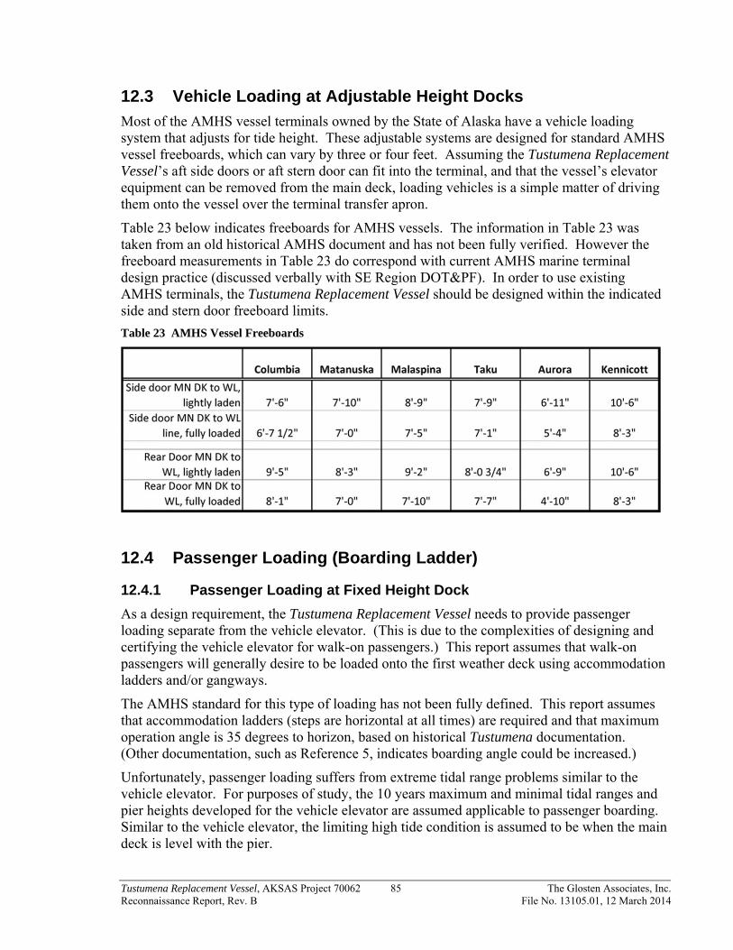
Tustumena Replacement Vessel, AKSAS Project 70062 85 The Glosten Associates, Inc. Reconnaissance Report, Rev. B File No. 13105.01, 12 March 2014
12.3 Vehicle Loading at Adjustable Height Docks
Most of the AMHS vessel terminals owned by the State of Alaska have a vehicle loading system that adjusts for tide height. These adjustable systems are designed for standard AMHS vessel freeboards, which can vary by three or four feet. Assuming the Tustumena Replacement Vessel’s aft side doors or aft stern door can fit into the terminal, and that the vessel’s elevator equipment can be removed from the main deck, loading vehicles is a simple matter of driving them onto the vessel over the terminal transfer apron.
Table 23 below indicates freeboards for AMHS vessels. The information in Table 23 was taken from an old historical AMHS document and has not been fully verified. However the freeboard measurements in Table 23 do correspond with current AMHS marine terminal design practice (discussed verbally with SE Region DOT&PF). In order to use existing AMHS terminals, the Tustumena Replacement Vessel should be designed within the indicated side and stern door freeboard limits.
Table 23 AMHS Vessel Freeboards
12.4 Passenger Loading (Boarding Ladder)
12.4.1 Passenger Loading at Fixed Height Dock
As a design requirement, the Tustumena Replacement Vessel needs to provide passenger loading separate from the vehicle elevator. (This is due to the complexities of designing and certifying the vehicle elevator for walk-on passengers.) This report assumes that walk-on passengers will generally desire to be loaded onto the first weather deck using accommodation ladders and/or gangways.
The AMHS standard for this type of loading has not been fully defined. This report assumes that accommodation ladders (steps are horizontal at all times) are required and that maximum operation angle is 35 degrees to horizon, based on historical Tustumena documentation. (Other documentation, such as Reference 5, indicates boarding angle could be increased.)
Unfortunately, passenger loading suffers from extreme tidal range problems similar to the vehicle elevator. For purposes of study, the 10 years maximum and minimal tidal ranges and pier heights developed for the vehicle elevator are assumed applicable to passenger boarding. Similar to the vehicle elevator, the limiting high tide condition is assumed to be when the main deck is level with the pier.

Tustumena Replacement Vessel, AKSAS Project 70062 86 The Glosten Associates, Inc. Reconnaissance Report, Rev. B File No. 13105.01, 12 March 2014
Figure 37 and Figure 38 below indicate the limiting height conditions for passenger boarding. These conditions occur in Homer and Seldovia. These heights are too great for any fixed deck standard accommodation ladder system. Further study will be necessary to identify a passenger boarding system that can accommodate the indicated height ranges. Improvements to the Homer and Seldovia piers could significantly improve the passenger loading situation.
Figure 37 Limiting High Tide Condition
Figure 38 Limiting Low Tide Condition

Tustumena Replacement Vessel, AKSAS Project 70062 87 The Glosten Associates, Inc. Reconnaissance Report, Rev. B File No. 13105.01, 12 March 2014
12.4.2 Passenger Loading at Adjustable Dock
The majority of the adjustable height terminals are owned and operated by the AMHS. The current practice at these terminals is to have passengers board the vessel using the terminal transfer apron and bridge. It is anticipated that this practice will continue. Therefore, if the Tustumena Replacement Vessel can load vehicles at the adjustable height terminals (discussed previously) then the requirement for passenger loading is also satisfied.
The Bellingham terminal (owned and operated by the Port of Bellingham) is currently the only terminal used by the AMHS with passenger boarding separate from vehicle loading. Since the Tustumena Replacement Vessel is not expected to visit this terminal frequently, it is recommended that the vessel arrangement not be specifically designed for the Bellingham terminal. Rather it is recommended that the passengers be loaded using the Bellingham terminal vehicle ramp, similar to the current practice for AMHS adjustable terminals.
12.5 Mooring Arrangement
12.5.1 Purpose
The intent of this section is to investigate the vessel to pier interface and determine if the Tustumena replacement vessel will fit at each pier.
The required ports of call for the Tustumena Replacement Vessel are defined in Section 12.1.2. The results of the terminal drawing search are given in Section 12.1.3. To determine pier interface, a plan view of the Tustumena Replacement Vessel (Reference 4) was inserted at each pier and located to provide the best access to the vehicle elevator. A separate vessel/pier interface drawing was created for each terminal. See Appendix I for individual terminal drawings.
Then the depth sounding, fender contact, and mooring line arrangements were examined and a summary of pier interface issues created. This summary is provided in Table 24, below.
12.5.2 Depth Sounding
The keel to underwater ground clearance (depth sounding) shown in the pier interface summary table is calculated at a vessel draft of 15.5 feet and at the lowest tide over the last 10 years. At this fairly onerous low tide level, three of the proposed terminals are rated poor and may cause vessel damage (Auke Bay East, Seldovia, and Whittier). Three terminals have about a fathom (six feet) under the keel of the vessel at extreme low tide, which was rated acceptable (Akutan, Chignik, and False Pass). All other terminals have ample water under the keel, even in extreme low tides.
The probability of the vessel encountering extreme low water occurs in a small portion of the total vessel operational window. It should be possible to overcome the low tide depth problem at the three poorly rated terminals by scheduling or waiting for the tide. A change in vessel depth is not recommended, pending further analysis and input from operational personnel.
Depth sounding information should be used with caution. The depth soundings around the piers came from bathometric data supplied with the pier design drawings. This information should be supplemented with actual soundings and vessel operational experience prior to

Tustumena Replacement Vessel, AKSAS Project 70062 88 The Glosten Associates, Inc. Reconnaissance Report, Rev. B File No. 13105.01, 12 March 2014
attempting to land at any pier. Also, local knowledge may be required to obtain accurate information about tidal variations and underwater changes.
Table 24 Pier Interface Summary
12.5.3 Fender Contact
The primary measure of acceptable pier interface is the length of fender contact. A longer fender contact length allows the vessel to be more securely lashed to the pier. In situations of short fender contact, particularly when all fender contact occurs aft of amidships, there is a high likelihood that the vessel could yaw at the face of the pier and disrupt vehicle elevator operations or cause damage to the vehicle elevator and vessel.
The fender contact and related issues for each pier are shown in Table 24. This information indicates that the current Tustumena Replacement Vessel could benefit from an increased length of the parallel fender face forward. With a one foot increase in mooring beam forward, seven of the piers change from acceptable to good fender contact length.

Tustumena Replacement Vessel, AKSAS Project 70062 89 The Glosten Associates, Inc. Reconnaissance Report, Rev. B File No. 13105.01, 12 March 2014
One terminal in particular is problematic. Although the dock at Chignik has recently been upgraded with the installation of three new dolphins, only a small portion (71 feet) of the Tustumena Replacement Vessel contacts the new dolphins. Both piers of the dock are old timber pile structures, circa 1960, which the 2012 Shore Condition Report notes to be in poor condition. Improvement to the fender contact length would likely require a fourth dolphin installed on the north side of the north pier. The possible improvement to the Chignik terminal is a facility engineering problem and there are no modifications to the Tustumena Replacement Vessel that could improve its fit at Chignik.
The Dutch Harbor terminal is missing some data and currently shows as marginal in regards to fender contact length. However, we have been advised that the old wooden pier is being ripped out and replaced, which should eliminate this problem. The Dutch Harbor drawing should be revised when new information is available.
Some piers have marginal fender spacing that is not reachable by the Tustumena Replacement Vessel at its currently proposed length and these piers are not a good fit for this vessel. Oddly enough this occurs at State owned terminals like Auke Bay, Ketchikan, and Valdez, where the vessel can only contact two fenders about 90 feet apart. At least at these terminals, vehicle elevator operation is not required.
Stern berth terminals fit the vessel reasonably well; however they all have a stern fit that is off center of the terminal apron. Depending on the width of the vessel’s stern door and associated structure, this issue may or may not be a problem. The fit of the Tustumena Replacement Vessel in the stern berths should continue to be monitored.
While all the focus of the fender contact has always been forward of the vehicle elevator, one interesting aspect of this analysis is the apparent fact that the fit of all terminals would be improved by increasing the length of the Tustumena Replacement Vessel aft of the vehicle elevator. In addition, vehicle elevator operations would be improved if the vehicle elevator was located in a section of parallel fender face.
12.5.4 Mooring
The vessel/pier interface drawings were provided with approximate mooring line placement, where bollard locations were known. These line placements are “notional,” as the vessel could be moored in many different configurations, and the intent was to get an idea of the range of mooring flexibility. In general, “good” mooring was defined as piers that support bow and stern quarter mooring lines, leading to bollards spaced greater than the vessel length. Mooring line spacing roughly equal to the vessel’s length was defined as acceptable, and mooring points provided at significantly less than vessel length was called marginal.
In general, most of the piers provide good mooring arrangements and three piers provide acceptable mooring. Only one dock was rated marginal and that is the Chignik terminal, which also has fender contact limitations. Likely the mooring at Chignik will be improved at the same time the piers are improved.
Additional study is required in the area of mooring to determine comprehensively the location of bollards and other mooring points and to investigate the location of mooring equipment on the vessel. For terminals with extreme tidal ranges, (like Homer) additional analysis is needed to examine the fleet angle of mooring lines in relation to the relative heights of mooring equipment.

Tustumena Replacement Vessel, AKSAS Project 70062 90 The Glosten Associates, Inc. Reconnaissance Report, Rev. B File No. 13105.01, 12 March 2014
Section 13 Candidate Shipyard Matrix
The M/V Tustumena Replacement Vessel will be a US Flag ship and as such will need to be constructed in the United States. A list of potential shipyards with existing facilities capable of constructing a 325 foot long ship has been tabulated in Table 25. A total of 16 companies have been identified as potential candidates for constructing the vessel, which includes some companies with multiple building yards.
Table 25 Candidate Shipyard Matrix
# Shipyard Loc'n Comments Likely
Bidder* Size
Category Street Address City State Zip
1 Aker Philadelphia EC Capable 0 L Philadelphia Nav. Bus. Ctr. Philadelphia PA 19112
2 AMFELS GC Primarily a rig builder
0 M 20000 Texas 48 Brownsville TX 78521
3 BAE Systems Southeast, Jacksonville
EC Capable 3 M 8500 Heckscher Drive Jacksonville FL 32226
4 BAE Systems Southeast, Mobile
GC Capable 3 M 660 Dunlap Drive Mobile AL 36652
5 Bollinger Marine GC Capable 5 M 4640 Peters Road Harvey LA 70058
6 Dakota Creek Industries WC LOA could be an issue
2 M 820 4th Street Anacortes WA 98221
7 Eastern Shipbuilding GC Capable 5 M 2200 Nelson Street Panama City
FL 32401
8 GD/NASSCO WC Capable 2 L Harbor Drive & 28th St San Diego CA 92113
9 Gulf Coast Shipyard Group GC Capable 4 M 13085 Seaway Road Gulfport MS 39503
10 Gulf Island Fabrication GC Capable 3 M 301 Bayou Dularge Rd Houma LA 70363
11 Gunderson Marine WC Capable 2 L 4350 N.W. Front Ave Portland OR 97210
12 Leevac Industries GC Capable 4 M Highway 90 East Jennings LA 70546
13 Marinette Marine GL Capable 3 M 1600 Ely Street Marinette WI 54143
14 Signal International GC Capable 4 M 11 N Water St Mobile AL 36602
15 Vigor Marine WC Capable 5 M 1801 16th Ave. S.W. Seattle WA 98134
16 VT Halter GC Capable 5 M 5801 Elder Ferry Road Moss Point MS 39563
* Scale: 0 - Highly Unlikely to 5 - Highly Likely
At this point in time, no shipyards have been contacted to determine willingness to participate in this project. However, based on the maritime industry sectors served by each shipyard, we have speculated as to which of these shipyards would be interested in bidding on this project. An unofficial scale was developed which ranged from “highly unlikely” for large navy oriented shipyards to “highly likely” for medium sized shipyards specializing in commercial work. From the 16 companies identified as having the capability to construct the new ferry, it is likely up to 6 or 8 of those companies would show interest in this project.
By way of comparison, for the Kennicott procurement 20 years ago, 3 shipyards actually submitted initial bidder qualifications of which 2 were down selected for submitting formal bids. It is important to maintain competition as far into the procurement process as possible, to ensure AMHS receives the best value possible.

Tustumena Replacement Vessel, AKSAS Project 70062 91 The Glosten Associates, Inc. Reconnaissance Report, Rev. B File No. 13105.01, 12 March 2014
Section 14 Procurement Approaches
14.1 General Procurement Considerations
The Tustumena Replacement Vessel is complex with unique features not seen anywhere else in the world. The mission of the vessel is complex as it serves numerous ports throughout Alaska. Vehicle and passenger loading offer unique challenges due to the extreme tidal ranges in many underdeveloped ports. The routes of the vessel expose it to some of the extreme weather in the world including sea state, wind, ice, and cold.
More traditional vessels such as fast ferries, cargo ships, fishing and cargo vessels are typically the result of ongoing design and operational refinement of predecessor or similar type vessels. The level of design information needed by the shipyard is more limited as the mission and goals are closely aligned to similar types of vessels.
There are various procurement strategies commonly used to acquire a new vessel with the ultimate goal of obtaining the “right” vessel for a reasonable cost with the least technical and financial risk. The “right” vessel is defined as that vessel capable of performing its design mission and that the owner can economically operate and maintain throughout the defined life of the vessel.
There are three major challenges in the procurement of any vessel, regardless of complexity or mission:
1. The timing of the risk transfer 2. Overall project schedule 3. Vessel unique features
One of the major challenges in any vessel procurement involves the timing of the transfer of design risk and the associated cost implications. Because of a vessel’s complexity, all parties to the contract have or will be assigned some portion of the design. Who, and the extent of their design responsibility, determines in large part their technical responsibility. Along with the assignment of technical risk there are significant cost and schedule implications. At their most fundamental level, the variations in the procurement strategies revolve around the point in the vessel design where the owner turns design responsibility over to the shipyard.
Another major factor in vessel procurement is overall project schedule, as it relates to the vessel design, and the timing of the contract between vessel owner and shipyard. A vessel owner may face schedule constraints to get a shipyard under contract for construction quickly. Several reasons may play into the schedule pressure such as: the availability of financing or the need to secure a vessel charter or operating agreement. Such external schedule pressure may play a significant role in the selection of the procurement method.
A third major factor influencing the vessel procurement is uniqueness or unique features that drive the design and construction of the vessel. When considering the procurement method for the replacement for the M/V Tustumena two unique features need to be considered. The vessel is required to be designed in large part around these two challenging features. As such, shipyards may not be interested or have the capability to properly and adequately address these. Specifically we are talking about:

Tustumena Replacement Vessel, AKSAS Project 70062 92 The Glosten Associates, Inc. Reconnaissance Report, Rev. B File No. 13105.01, 12 March 2014
Engine Emissions - Tier 4 emission requirements will require components (scrubbers) and chemicals (urea) to meet these requirements. The M/V Tustumena replacement will be one of the first vessels in this country having to meet these requirements.
Vehicle Elevator - The Tustumena Replacement Vessel is designed around the vehicle elevator. Regulations and requirements have evolved since the last one was built and installed on the M/V Kennicott approximately 20 years ago. This one piece of very complex equipment and its dependability is critical to the operation of the vessel.
14.2 Overview of Procurement Strategies
The objective of the vessel owner in a new vessel acquisition is to acquire a new vessel that meets the contracted requirements with the lowest overall cost, considering both initial capital cost and lifecycle cost. The objective of the shipyard in a new vessel acquisition is to deliver a new vessel that satisfactorily meets the contracted requirements for the lowest initial capital cost to the shipyard.
To explain the different procurement strategies and discuss their various advantages and disadvantages it is helpful to review usual design process/steps involved in acquiring a new vessel and the associated timeline.
Establish vessel mission requirements.
Concept Design
Preliminary Design
Contract Design
Design Verification/Functional Design
Detail Design/Construction Drawing Development
Vessel Construction
Vessel Testing and Acceptance
Warranty Period
These steps need to happen no matter which procurement method is selected. Some overlap between the stages is possible, depending on the structure of the acquisition contract. Development of the contract documents outlining the extent of each party’s role in the vessel acquisition can happen at any point from Stage 2 through Stage 6. Figure 39 shows these various stages on a typical timeline with some allowance for overlap between the stages.
Figure 39 Vessel Acquisition Stages

Tustumena Replacement Vessel, AKSAS Project 70062 93 The Glosten Associates, Inc. Reconnaissance Report, Rev. B File No. 13105.01, 12 March 2014
The various procurement strategies fall under two broad categories or approaches:
1. Design/Bid/Build 2. Design/Build
As mentioned above, the primary difference between these procurement methods is the level that the vessel design is developed to at the transfer of responsibility (contract signing) between the owner and the shipyard. Both methods, and variants thereof, have been used successfully on many public vessel acquisition projects.
The State of Alaska has successfully contracted for the building of at least eight car/vehicle ferries in the last 20 years. Both Design/Build variants and Design/Bid/Build variants have been used in those acquisitions. Table 26 provides a summary of the ferry acquisitions.
Table 26: Summary of Recent Vessel Procurements
Vessel Name(s) Procurement Method Vessel Design Reponsibility
M/V Kennicott Design/Build with Owner’s Model Design shipyard
M/V Fairweather & M/V Chenega
Design/Build shipyard
M/V Prince of Wales & M/V Stikine
Design/Bid/Build with Full Design Package owner
M/V Lituya Design/Bid/Build with Full Design Package owner
M/V Oral Freeman Design/Build with Guidance Drawings shipyard
M/V Ken Eichner 2 Design/Build with Guidance Drawings shipyard
14.3 Traditional Design/Bid/Build Procurement Approach
A traditional Design/Bid/Build procurement approach has eight main steps, which are presented in Figure 40.
The owner, usually in consultation with a naval architecture firm, accomplishes Steps 1 through 4, develops a set of bidding documents, solicits bids from shipyards, and awards a contract to a shipyard. The shipyard then accomplishes Steps 5 through 9 under the supervision of the vessel owner.
Figure 40 Design Responsibility Transition, Traditional Design/Bid/Build Approach

Tustumena Replacement Vessel, AKSAS Project 70062 94 The Glosten Associates, Inc. Reconnaissance Report, Rev. B File No. 13105.01, 12 March 2014
Contract designs in this approach are traditionally completed to a level that defines all elements where the owner has particular requirements or preferences as well as suitable levels for class submittals. It typically allows the shipyard to develop a complete and detailed cost and construction estimate for bidding purposes. The Owner’s Design clearly specifies the major elements of the ship allowing the shipyard to put a price on the work accurately without doing significant additional design work. The design and engineering work carried out by the shipyard after contract award is primarily production engineering necessary to fabricate and install the specific items and equipment specified by the owner. The shipyard is not checking the Owner’s Design but rather implementing the Owner’s Design.
This vessel acquisition approach minimizes the risk of not getting the “right” vessel. The owner bears the majority of design responsibility and associated cost and engineering risks with design development, discovered work and most other contract changes.
Pros
Owner gets exactly what is asked for and theoretically what is wanted.
Assuming the contract design is mature:
o The owner gets a realistic price and schedule from the shipyard o Level playing field for all bidding shipyards. o Risks from the shipyard’s perspective are known and contingencies should be
reasonable o Contract design can be submitted to ABS/USCG limiting submittals by the shipyard
during construction and mitigating owner and shipyard regulatory review changes and risk.
Shipyard basically responsible for ordering material and building vessel which they are reasonably good at (i.e. they want to build a ship, not design it).
Cons
Limited transfer of design risk.
Takes more time to develop the contract design and get the shipyard on contract.
Risks
Owner assumes the majority of the fundamental design risk and the associated cost to resolve.
Owner review should emphasize conformance to the contract and limit design development input (except as allowed by the contract).
14.4 Design/Bid/Build Variations
The owner’s design risk in the typical Design/Bid/Build process can be reduced by introducing a “go”/ “no go” stage gate after the shipyard accomplishes the Functional Design (i.e. at Stage 5 in Figure 40). Additionally this phase (Stage 5) can be expanded to include “design verification” by the shipyard that leads to a contractual acceptance by the shipyard of design responsibility (i.e. design transfer).

Tustumena Replacement Vessel, AKSAS Project 70062 95 The Glosten Associates, Inc. Reconnaissance Report, Rev. B File No. 13105.01, 12 March 2014
During development of the Functional Design/Design Verification, should elements of the Owner’s Design be proven deficient, the owner and shipyard then negotiate the cost of the design and procurement changes. This allows the owner the opportunity to transfer a significant portion of the design responsibility to the shipyard prior to construction. The down side of the additional step is increased cost to the owner for the additional design verification step and its results.
The shipyard would be contractually required to complete the Functional Design/Design Verification prior to ordering equipment and beginning construction. In essence it is a “go”/”no go” gate for both parties.
Pros
Owner gets exactly what is asked for and gets to see it at the functional level.
Owner has transferred a significant amount of the design risk.
Assuming the contract design is mature:
o The Owner gets a realistic price and schedule from the shipyard. o Changes identified during design verification should result in minimal delays as the
consequences and time of this step are built into the shipyard schedule o Level playing field for all bidding shipyards. o Risks from the shipyard’s perspective are known and contingencies should be
reasonable. Design verification enhances and further quantifies the risks associated with the design to both parties. This step provides a controlled period for both parties to resolve issues before proceeding to construction.
o Contract design can be submitted to ABS/USCG limiting submittals by the shipyard during construction and mitigating Owner regulatory review changes and risk.
o Functional design elements needing submittal to ABS/USCG can be submitted by the shipyard minimizing regulatory delays during vessel construction.
Shipyard basically responsible for ordering material and building the vessel, which they are reasonably good at (i.e. they want to build a ship not design it).
Cons
Takes more time to develop the contract design and get the shipyard on contract.
There is a “go”/”no go” gate built into the shipyard construction contract. The formal review and acceptance of the shipyard functional design will push out the delivery of the vessel in the shipyard schedule.
There is a cost increase associated with the additional verification step. The shipyard is required to spend more time and effort completing the functional design of the vessel.

Tustumena Replacement Vessel, AKSAS Project 70062 96 The Glosten Associates, Inc. Reconnaissance Report, Rev. B File No. 13105.01, 12 March 2014
Risks
Owner review should emphasize conformance to the contract and the documents developed as part of the design verification. Very limited Owner design development input after NTP with construction.
The Shipyard may wish to abandon the construction of the vessel as a result of/during the design verification. While unlikely, it is a remote possibility.
Built in delay for vessel delivery due to the formal design verification. Delay can be mitigated somewhat by allowing early ordering of certain long lead/critical material based upon the confidence in the functional design/design verification.
14.5 Traditional Design/Build Procurement Approach
The owner accomplishes Step 1 (Performance Requirements) with a set of bidding documents, solicits bids from shipyards, and awards a contract to a shipyard. The shipyard then accomplishes Steps 2 through 8 under the supervision of the vessel owner. See Figure 41. The bidding documents are performance related and leave most technical decisions up to the shipyard. Cruising speed, draft limitations, vehicle/passenger capacity, terminal interfaces, etc. are typical attributes that will be found in a performance specification. The shipyard is responsible for all vessel design activities.
Figure 41 Design Responsibility Transition, Design Build Approach
While this method is used successfully in Europe and Asia, U.S. shipyards typically do not have large in-house design teams. This makes responding to design/build contracts challenging and expensive. Typically the shipyard retains an outside design agent to develop a design to a suitable level for costing and risk assessment. This allows the shipyard to estimate the work and develop a bid. The designer and shipyard may not be compensated for this effort. Because of cost and time limitations, the shipyard, and their design agent are left with the task of assessing the risk and developing a cost contingency in the bid to cover this risk. For simple vessel designs this can be the least cost but depending on the uniqueness of the design or the technical challenges posed by the design requirements, this may result in the owner paying a significantly higher cost for the vessel.
This procurement approach is well suited for repeatable/follow on vessel design configurations. This method is most likely to result in having the shipyard under contract in the shortest time. This method may result in quicker delivery of a new vessel.
For challenging, unique vessel designs, such as the Tustumena Replacement Vessel, this approach has the greatest technical risk. This is because the shipyard performing the design

Tustumena Replacement Vessel, AKSAS Project 70062 97 The Glosten Associates, Inc. Reconnaissance Report, Rev. B File No. 13105.01, 12 March 2014
(or their design agent) may not bring any past experience from similar vessels or have a thorough understanding of the challenges of the Tustumena’s service.
Pros
Can be the least cost option if technical challenges are limited.
Design risk is transferred to shipyard almost entirely.
Obligate all construction funds after DSR development.
Cons
Shipyards have limited design staff. Significant effort is required to put together a comprehensive bid and schedule. There is also significant cost/schedule risk to both parties.
High technical risk as shipyard may have very little experience with challenges associated with this vessel.
Owner has the most risk of not getting what is wanted and needed. The Tustumena Replacement Vessel has many unique features and leaving design decisions in the hands of the shipyard who are interested in building vessels could result in abbreviated and limited analysis of the unique features and result in a significant shortfall in the performance of this one-off design.
Owner has limited participation in the subsequent design of the vessel.
Limited bidding pool. Shipyards that do participate may simply assign large contingencies/risk allowances to cover the unknowns.
Highest cost/schedule risk to all parties.
Risks
If there are strong owner preferences and needs that only come out after the award of contract then the owner has significant cost and technical risk. You only get what you specify.
Process most suitable for vessels similar to existing vessel where shipyard has some historical cost and design data information.
Because of the design risks, costs and unknowns may not get any bidders.
14.6 Design/Build Variations
To address the concern over the loss of design control by the owner, modern variations to the traditional design/build approaches have focused on two areas:
1. Providing a non-binding design through Stage 2 or Stage 3 (i.e. owner’s model design) to give the shipyard an idea of the owner’s expectations. This was done successfully on Kennicott.
2. Adding stage gates into the design timeline which give the owner more ability to review and comment/change the design as it is developed by the shipyard.
The owner and shipyard then negotiate the cost of design changes. This gives the owner the ability to influence the design at the added expense of increased cost or schedule risk should

Tustumena Replacement Vessel, AKSAS Project 70062 98 The Glosten Associates, Inc. Reconnaissance Report, Rev. B File No. 13105.01, 12 March 2014
negotiations with the shipyard over desired changes prove unsuccessful, resulting in the owner terminating the contract.
Pros
The intent of this process is to allow the maximum flexibility to the shipyard to meet the basic owner specified contract requirements
Owner can specify hold points in the design to review certain elements. Changes after the accepted contract design, would be change orders
Provides shipyard with design risk but still gives the owner some design control
Cons
Shipyard makes bid based upon limited design information. This can be mitigated to some extent by paying “approved bidders” a small amount to do limited design to bring more fidelity to their bid- all approved bidders would be paid the same amount.
Process is typically specification/performance driven and the owner has limited input into the details
Difficult for the owner and owner’s representative to not try to steer the design and construction to meet their expectations. This can lead to friction with the shipyard and potential claims for overzealous owner action
Risks
The risk of the shipyard making a bid based upon limited information and then coming back to the owner for additional compensation can be mitigated by inserting a requirement for the shipyard to carry out a contract design before the start of construction. The owner can then either:
o Accept the design as is o Accept the design with items to be corrected/clarified o Abandon the process and the procurement
Normally the shipyard would be allowed an opportunity to revisit their bid especially in light of owner review and comments. This would be a critical step to avoid/minimize claims
Upon completion and acceptance of the shipyard contract design the owner’s role is one of verifying compliance with the contract (i.e. the contract design) and quality
14.7 Detail Design by Owner
This is a variant of the preceding approaches, often compared to the “general contractor approach” for commercial shoreside projects. It involves a close partnership between the owner and the shipyard, such that the owner’s naval architect is entrusted with developing the detail design documents to be used by the shipyard for actual construction.
The advantage of this approach derives from the fact the owner’s naval architect is intimately familiar with the design, and many modern shipyards (at least in the U.S.) do not have sufficient in-house engineering capability to accomplish the detail design, but must rely on

Tustumena Replacement Vessel, AKSAS Project 70062 99 The Glosten Associates, Inc. Reconnaissance Report, Rev. B File No. 13105.01, 12 March 2014
outside contracted services. Thus there is some efficiency captured by extending the role of the owner’s naval architect through the shipyard detail design process.
As vessels are so unique with many custom elements that are only truly developed during the shipyard design portion of the contract, the designer is pulled two ways as his role is transferred from one of assisting the owner in developing the design and protecting his objectives to one of supporting the shipyard and their objectives and drivers. The competing objectives of the owner and the shipyard leave the designer caught in the middle. This results in the loss of the independent reviewer role traditionally fulfilled by the owner’s naval architect and the introduction of certain elements of conflict-of-interest in the naval architect’s role (as the naval architect now owes a duty to both the owner and the shipyard).
While all procurement processes rely on good collaboration between all parties to be successful, this method is particularly dependent on establishing and maintaining good collaboration between all parties.
Pros
No learning curve for the naval architect-they are able to seamlessly transition to the functional/detail design
Naval architect can quickly clarify and resolve minor discrepancies with minimal cost to the owner
Depending upon the bidding and selection process, the naval architect should be able to provide insight and comments that should bring more fidelity to the shipyard bid and make them aware of the inherent risks and weakness in the design (i.e. things needing additional design development)
Cons
Owner loses his naval architect and their knowledge to;
o Champion the owner’s desires and wishes o Support the adjudication process o Provide oversight and evaluation of potential problems and issues
Naval architect will be required to balance the wants and wishes of both parties.
Shipyard process will be difficult. Selection depends upon finding someone where the key to success is continuous cooperation and openness.
Risks
Selection of shipyard is key to success. Must be a partner in the process
Successful project will be determined by the ability of the shipyard and the owner to treat each other fairly and equitability and to develop a process for adjudicating changes that both parties accept and support.
Need some type of impartial panel of “experts” to adjudicate ongoing changes and issues
14.8 Summary and Recommendations
The Tustumena Replacement Vessel represents a unique and challenging design opportunity for potential contractors. The vehicle handling system, the extreme tidal ranges, the
Tustumena Replacement Vessel, AKSAS Project 70062 100 The Glosten Associates, Inc. Reconnaissance Report, Rev. B File No. 13105.01, 12 March 2014
challenging environmental conditions, and the current regulatory environment combine to present a formidable vessel design challenge. There are two developed vessel design examples in North America: the 50 year old Tustumena and the 15 year old Kennicott, both owned and operated by AMHS. This means that the greatest source of experience for the new vessel design resides within AMHS. To capture and maximize the value of that experience means the acquisition process should maintain owner design involvement for as long as possible. Several procurement approaches maintain owner design involvement late into the design development. As schedule plays an important role in determining the procurement method, once AMHS has a more firm project schedule developed, a recommended procurement method will be suggested.


