13.1 Canal Regulation 13.2 Canal Regulation...
36
13.1 Canal Regulation 13.2 Canal Regulation Works
Transcript of 13.1 Canal Regulation 13.2 Canal Regulation...

13.1 Canal Regulation
13.2 Canal Regulation Works

13.3. Alignment of the off-taking channel

3
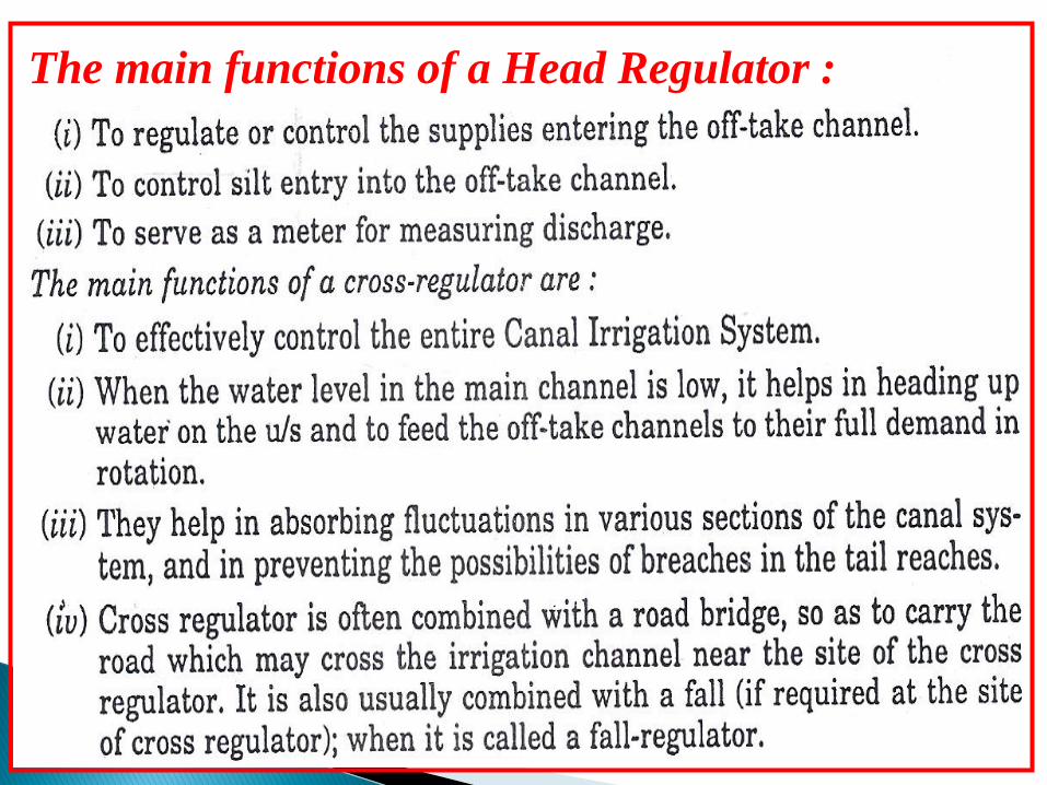
The main functions of a Head Regulator :

13.5. Design of Cross Regulator and Head RegulatorCrest Levels.
Water-way
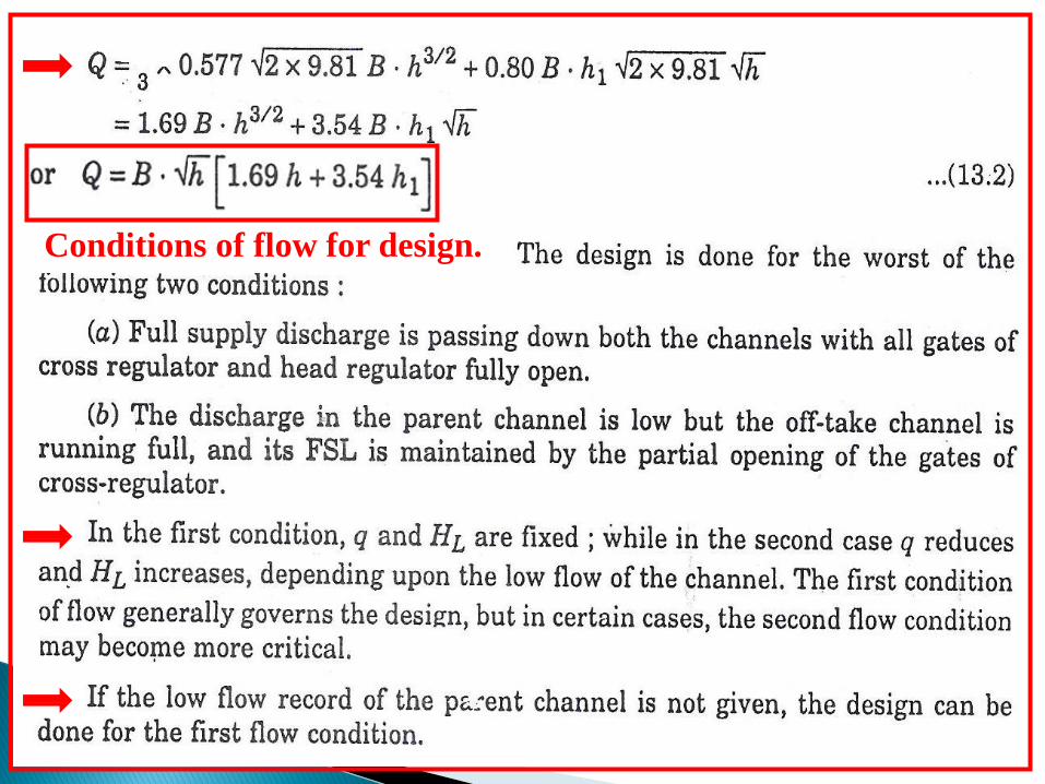
Conditions of flow for design.

Downstream Floor Level or Cistern Level.
Length of d/s Floor.
Cut-offs are provided as given below :
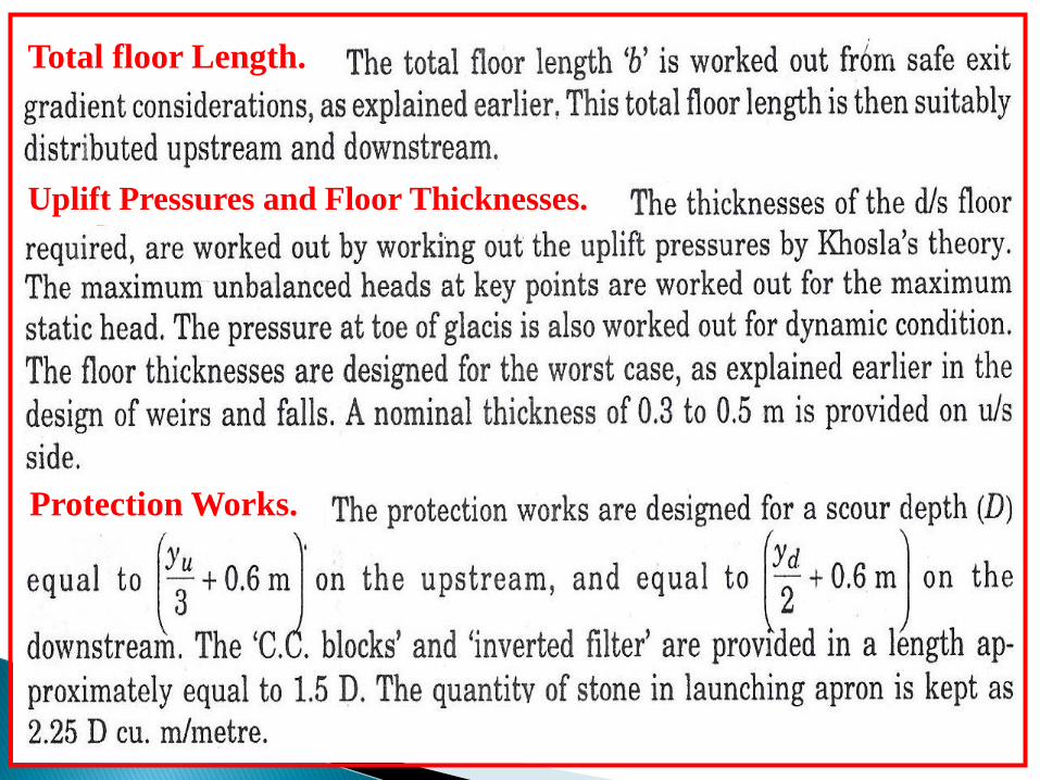
Total floor Length.
Uplift Pressures and Floor Thicknesses.
Protection Works.

Example 13.1

(A) Design of Cross Regulator
Provide Crest at R.L. 207.5 m.
Provide 5 bays of 8.0 m eachProvide 4 piers of 1.5 m

Hence, prove the cistern ord/s floor at R.L. 207.3 m.


DIVERSION HEADWORKS


Vertical cut-offs

Total Floor Length from Exit Gradient Considerations

Calculations for Uplift pressures

(corrected)

Floor Thicknesses : D/S Floor
Provide 1.4 m.
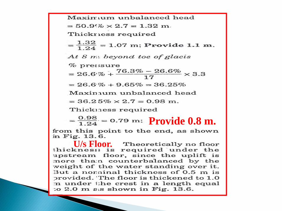
U/s Floor.
Provide 0.8 m.
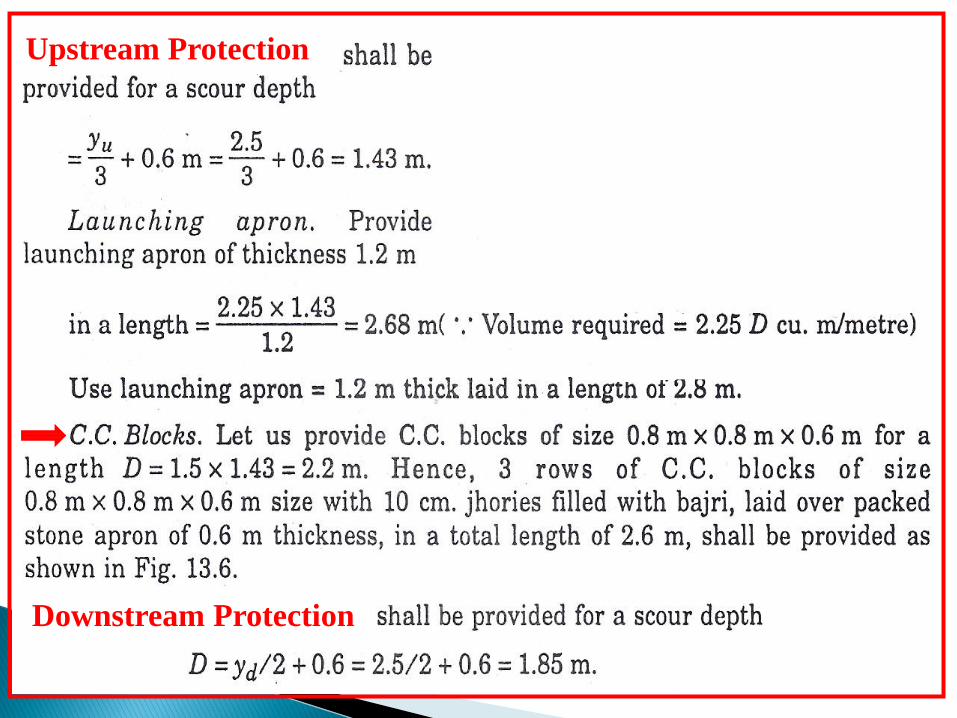
Upstream Protection
Downstream Protection


Bed Level of Distributary
Hence keep the crest of Head Regulator at RL 208.1 m.


R.L. of cistern
The bottom level of u/s cutoff
The bottom of d/s cut-off

Total Floor Length from Exit Gradient Considerations

Hence, Provide d/s floor length = 14 m.
Calculation for Uplift Pressures
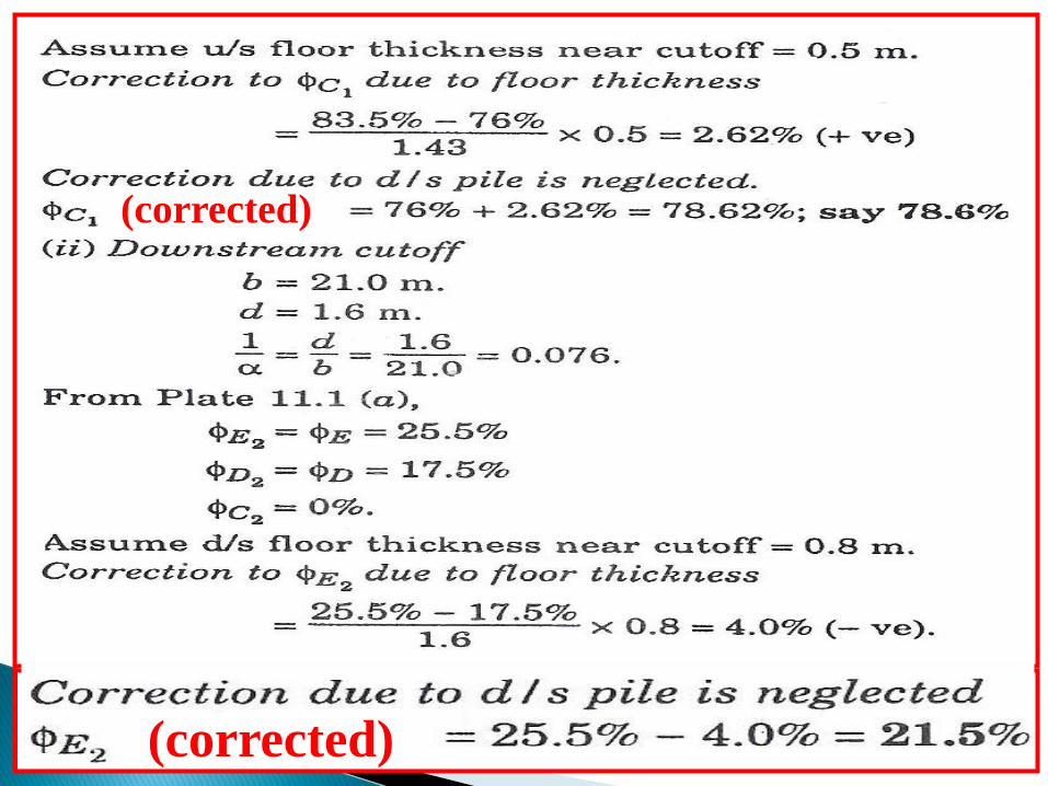
(corrected)
(corrected)
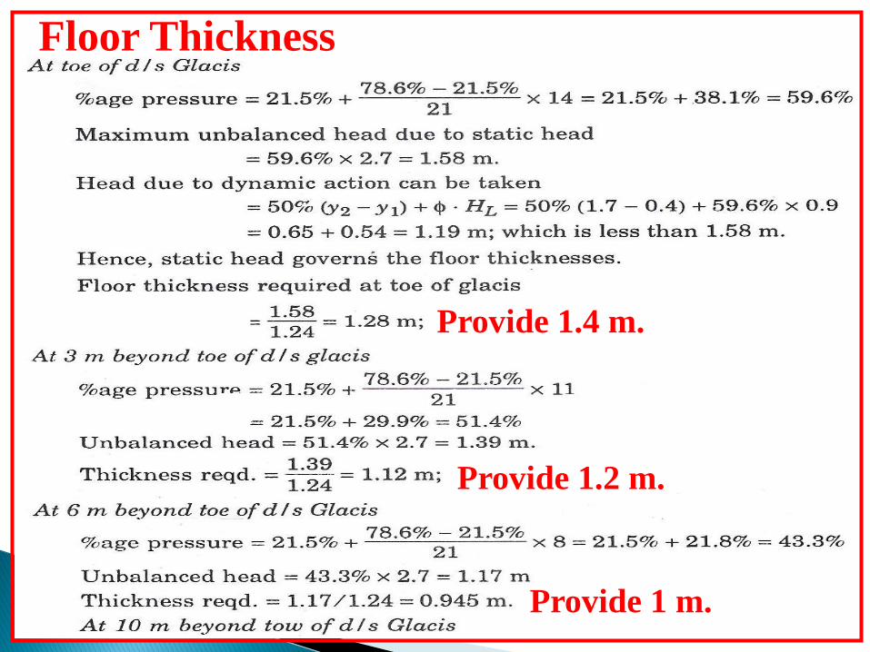
Floor Thickness
Provide 1.4 m.
Provide 1.2 m.
Provide 1 m.
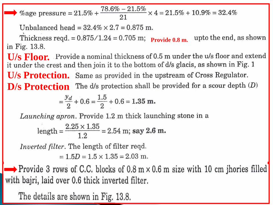
U/s Floor.
U/s Protection.
D/s Protection
Provide 0.8 m.