13 · configured to provide Option 66. Refer to section 4.4.3. 3 Creating a Device Profile ... HTTP...
43
Zultys, Inc. 785 Lucerne Drive, Sunnyvale, California, USA 94085 www.zultys.com Author: Zultys Technical Support This document provides detailed information related to the installation and configuration of the Zultys ZIP 33i & ZIP 35i IP Phones. The document also covers the ‘ZIP 340M LCD Expansion Module’ and ‘EHS 3xi Electronic Hook Switch Adapter’ accessories that are compatible with the ZIP 35i. Where the term ‘ZIP 3xi’ appears in this manual the information relates to the ZIP 3xi series of phones being the ZIP 33i and ZIP 35i. Refer to Section 1 for important information regarding ZIP 3xi and MX firmware requirements. March 13 ZIP 3xi Installation and Configuration Guide (Rev 4a) Technical Publications
Transcript of 13 · configured to provide Option 66. Refer to section 4.4.3. 3 Creating a Device Profile ... HTTP...

08 Fall
Z u l t y s , I n c . 7 8 5 L u c e r n e D r i v e , S u n n y v a l e , C a l i f o r n i a , U S A 9 4 0 8 5 w w w . z u l t y s . c o m
Author: Zultys Technical Support This document provides detailed information related to the installation and configuration of the Zultys ZIP 33i & ZIP 35i IP Phones. The document also covers the ‘ZIP 340M LCD Expansion Module’ and ‘EHS 3xi Electronic Hook Switch Adapter’ accessories that are compatible with the ZIP 35i. Where the term ‘ZIP 3xi’ appears in this manual the information relates to the ZIP 3xi series of phones being the ZIP 33i and ZIP 35i. Refer to Section 1 for important information regarding ZIP 3xi and MX firmware requirements.
March 13
ZIP 3xi Installation and Configuration Guide (Rev 4a)
Technical Publications

ZIP 3xi Installation and Configuration Guide (0000000359) Revision 4a / March 28, 2013
© 2013 Zultys, Inc. No reproduction or distribution without permission Page 2 of 43
Technical Publications
Contents
1 FIRMWARE REQUIREMENTS ...................................................................................................................... 3
2 OVERVIEW OF THE DEPLOYMENT PROCESS ........................................................................................ 4
3 CREATING A DEVICE PROFILE .................................................................................................................... 4
4 OVERVIEW OF PROFILE TABS .................................................................................................................... 6
4.1 GENERAL TAB ................................................................................................................................................... 6 4.2 REGIONAL TAB .................................................................................................................................................. 8 4.3 SIP TAB ............................................................................................................................................................. 9 4.3.1 LINES ............................................................................................................................................................................... 9 4.4 IP & PROVISIONING TAB ............................................................................................................................... 10 4.4.1 LAN ............................................................................................................................................................................... 11 4.4.2 SERVERS ........................................................................................................................................................................ 11 4.4.3 PROVISIONING .............................................................................................................................................................. 12 4.4.4 MANUALLY CONFIGURING THE PROVISIONING SERVER ........................................................................................ 13 4.5 AUDIO & RTP ................................................................................................................................................. 15 4.5.1 DTMF FOR RTP .......................................................................................................................................................... 15 4.5.2 CODECS .......................................................................................................................................................................... 16 4.5.3 QUALITY OF SERVICE: TOS/DIFFSERV .................................................................................................................... 17 4.5.4 RING TONES .................................................................................................................................................................. 17 4.5.5 MISCELLANEOUS .......................................................................................................................................................... 17 4.6 VLAN TAB ...................................................................................................................................................... 18 4.6.1 LAN PORT .................................................................................................................................................................... 19 4.6.2 PC PORT ........................................................................................................................................................................ 19 4.6.3 LLDP ............................................................................................................................................................................. 19 4.6.4 VLAN CONFIGURATION EXAMPLES ......................................................................................................................... 20 4.7 KEYS TAB ........................................................................................................................................................ 21 4.7.1 LABEL TEMPLATE ........................................................................................................................................................ 21 4.7.2 TYPE ............................................................................................................................................................................... 23 4.7.3 VALUE ............................................................................................................................................................................ 25 4.7.4 LINE ............................................................................................................................................................................... 25 4.8 ADVANCED TAB .............................................................................................................................................. 25
5 OVERVIEW OF ZIP 340M EXPANSION MODULE ................................................................................. 27
5.1 POWERING ZIP 340M EXPANSION MODULES ............................................................................................ 27 5.2 USING ZIP 340M’S AND EHS 3XI ELECTRONIC HOOK SWITCH ADAPTER TOGETHER............................ 27 5.3 PROVISIONING ZIP 340M EXPANSION MODULES ...................................................................................... 27
6 EHS 3XI ELECTRONIC HOOK SWITCH ADAPTER ............................................................................... 29
6.1 CONNECTING A PLANTRONICS WIRELESS HEADSET .................................................................................... 30 6.2 CONNECTING A GN NETCOM/JABRA WIRELESS HEADSET ......................................................................... 31

ZIP 3xi Installation and Configuration Guide (0000000359) Revision 4a / March 28, 2013
© 2013 Zultys, Inc. No reproduction or distribution without permission Page 3 of 43
Technical Publications
7 ADDING A DEVICE ......................................................................................................................................... 32
8 FIXED FUNCTION KEYS ............................................................................................................................... 34
9 CONTROLLING CONFIGURATIONS .......................................................................................................... 36
9.1 CONFIGURATION METHODS ........................................................................................................................... 36 9.2 PHONE INITIALIZATION ................................................................................................................................. 36
10 UPGRADING FIRMWARE .......................................................................................................................... 36
10.1 UPGRADING FIRMWARE VIA DEVICE PROFILE ........................................................................................... 36 10.2 UPGRADING FIRMWARE VIA WEB INTERFACE ........................................................................................... 38
11 TROUBLESHOOTING TIPS AND TOOLS ............................................................................................... 39
11.1 FACTORY RESETTING PHONE ...................................................................................................................... 39 11.2 REBOOTING PHONE ...................................................................................................................................... 39 11.3 PHONE DOES NOT USE THE CONFIGURATION FILE ON TFTP SERVER ...................................................... 40 11.4 HOW TO CHECK IF CONFIGURATION FILE IS DOWNLOADED ...................................................................... 40 11.5 PERFORMING A NETWORK PACKET CAPTURE USING THE PHONE ............................................................ 40 11.6 CAPTURING SYSLOG INFORMATION ............................................................................................................ 41 11.6.1 CAPTURING SYSLOG INFORMATION LOCALLY ON PHONE ................................................................................... 41 11.6.2 ENABLING SYSLOG OUTPUT TO EXTERNAL SERVER VIA WEB INTERFACE ....................................................... 42 11.6.3 ENABLING SYSLOG OUTPUT TO EXTERNAL SERVER VIA CONFIGURATION FILE .............................................. 42
12 EMERGENCY RECOVERY MODE ............................................................................................................. 43
1 Firmware Requirements
To ensure correct operation of the ZIP 33i and ZIP 35i IP phones the following firmware requirements must be strictly adhered to.
ZIP 33i with firmware 60.61.132.12 or earlier – MX firmware 7.2.4 or later is required
ZIP 33i with firmware 60.61.132.15 or later – MX firmware ‘7.2.4 + Patch 7203’ or later is required.
ZIP 35i with firmware 65.61.132.15 or later – MX firmware ‘7.2.4 + Patch 7203’ or later is required.
Important Note: Do not update the firmware of a ZIP 33i to 60.61.132.15 or later, prior to first upgrading the MX system to the required firmware/patch level noted above. The syntax for the ZIP 33i SIP Server settings changed from firmware 60.61.132.15 onwards. MX Admin starting from ‘7.2.4 + Patch 7203’ generates ZIP 33i configuration files that are compatible with 60.61.132.12 and earlier firmware as well as 60.61.132.15 and later firmware.

ZIP 3xi Installation and Configuration Guide (0000000359) Revision 4a / March 28, 2013
© 2013 Zultys, Inc. No reproduction or distribution without permission Page 4 of 43
Technical Publications
In the event that a ZIP 33i is upgraded prior to the MX system being at a compatible firmware release, or if the device or profile was not edited after upgrading the MX, the device configuration files will need to be regenerated.
Starting with MX Admin 7.2.4 + Patch 7203 device configuration files may be regenerated by right-clicking on the device in the ‘Configure | Devices’ screen and selecting ‘Regenerate configuration files’. The configuration files will be regenerated immediately and downloaded by the phone the next time it is power cycled or an update is pushed to it assuming it is currently registered. In both cases, it is assumed that the phone is able to contact the MX system’s TFTP server.
2 Overview of the deployment process
This document covers the steps required to provision, deploy and manage the Zultys ZIP 33i and ZIP 35i IP phones with a Zultys MX system. ZIP 33i phones are supported in MX Release 7.2.4 and later, the ZIP 35i phones are supported in MX Release 7.2.4 when patch 7203 is applied, as well as later MX firmware releases. Prior to Release 7.2.4 there is no support for the ZIP 33i or ZIP 35i phones.
In general the steps required to successfully deploy a ZIP 3xi phone are:
Upload the current phone firmware ROM file to the TFTP server of the MX system for the model being deployed. Firmware versions starting with “60.” relate to the ZIP 33i, versions starting with “65.” relate to the ZIP 35i. The current firmware release for each model is available from the Zultys Knowledge Base System (http://kbs.zultys.com). Refer to section 10.
Create a device profile with the relevant settings, including selection of the firmware version to be used by the ZIP 3xi phones. Refer to section 3.
Add the ZIP 3xi devices to the MX system and assign the appropriate device profile. Refer to section 7.
Add new users to the MX system, if required, then assign the newly provisioned devices to their respective users.
To use automatic provisioning ensure that the DHCP server is correctly configured to provide Option 66. Refer to section 4.4.3.
3 Creating a Device Profile
A Device Profile defines a common set of configuration options that will be applied to all phones that are allocated a particular Device Profile. This greatly simplifies the management of deployed phones as changes only need to be performed in one place.

ZIP 3xi Installation and Configuration Guide (0000000359) Revision 4a / March 28, 2013
© 2013 Zultys, Inc. No reproduction or distribution without permission Page 5 of 43
Technical Publications
Prior to creating a new Device Profile, the system administrator should ensure that the current firmware ROM file for the model being deployed has been uploaded to the TFTP server of the MX system. Refer to section 10 for further information.
To create a new ZIP 3xi device profile:
1. In MX Administrator, select Configure | Devices.
2. Click the Profile button in the Managed Devices window.
3. In the Device Profiles window, right-click Zultys Phones and select New to create a new device profile.
4. In the Add Device Profile window, set the Phone Type as required.
5. Type a Profile Name, in the screenshot above Sample_35i is used.
6. Refer to the section 4 for an explanation of the options configured via the Device Profile.

ZIP 3xi Installation and Configuration Guide (0000000359) Revision 4a / March 28, 2013
© 2013 Zultys, Inc. No reproduction or distribution without permission Page 6 of 43
Technical Publications
4 Overview of Profile Tabs
The device profile for each phone is divided into several tabs. Each tab configures different aspects of the profile.
4.1 General Tab The General tab contains settings related to firmware version and updating, password settings, and various miscellaneous settings.
Download protocol: Defines the protocol used by the phone to download new firmware.
o None – Phone will not check for new firmware on power up.
ZIP 3xi Installation and Configuration Guide (0000000359) Revision 4a / March 28, 2013
© 2013 Zultys, Inc. No reproduction or distribution without permission Page 7 of 43
Technical Publications
o TFTP – Phone will use TFTP (Trivial File Transfer Protocol) to download firmware image on power up if different to the currently installed version. This is the default setting.
o HTTP – Phone will use HTTP (Hyper Text Transfer Protocol) to download firmware image on power up if different to the currently installed version. HTTP may perform more reliably over poor quality links. TCP port 8080 is used when download protocol is HTTP and server set to MX.
Server: Defines the address of server where firmware image is stored.
o MX – Select this option when the internal TFTP/HTTP server of the MX system is to be used, this will be the case for most deployments. For HTTP TCP port 8080 is used.
Address – Lists the MX systems’ IP addresses including LAN, WAN and SBC Port Mapping addresses if configured. For external, for phones connecting to a WAN or SBC address you may need to configure port forwarding on external routers.
Filename – Lists the compatible firmware images stored on the MX TFTP server. Select the desired filename from the dropdown. If the files stored on the TFTP have recently been changed by another system administrator, click the Refresh button to update the list. If the field background is red the corresponding file is not present on the TFTP server and thus the phone will be unable to access the file. Files are uploaded to the TFTP server via the TFTP Settings window accessible from the Configure | Devices screen. Refer to section 10 for further information about the firmware upgrade process.
o Custom – Select when an external TFTP/HTTP server is to be used. In the corresponding address field type the full path and filename. For HTTP, both the address and port may be defined. TFTP example – 192.168.1.100/60.61.132.8.rom HTTP example – 192.168.1.100:8080/tftpphone/60.61.132.8.rom
Phone Administration: Set passwords used to access various restricted sections of the phone interface and the web interface.
o Local User Password – Password to access User level restricted sections. Default is ‘user.’ If the field is left blank, then no password is required.
o Local Administrator Password – Password to access Administrator level restricted sections. Default is ‘admin.’ If the field is left blank, then no password is required.

ZIP 3xi Installation and Configuration Guide (0000000359) Revision 4a / March 28, 2013
© 2013 Zultys, Inc. No reproduction or distribution without permission Page 8 of 43
Technical Publications
Busy Lamp Field
o BLF Subscription Period: The period in seconds a Busy Lamp Field subscription will last before phone re-subscribes. Default is ‘3600.’
Miscellaneous:
o Missed Call Indicator – When enabled, the phone will display the number of missed calls on the idle screen and also store caller details for the missed calls in the Call Log. When disabled, no missed call indication will be displayed and the phone will not store any information about the missed call in the Call Log.
o Auto-answer Intercom calls – When set to Yes, the phone will automatically answer received Intercom calls. When set to No, the phone will ring when an Intercom call is received. Default is ‘Yes.’
o Mute Intercom calls – This setting is fixed at ‘No.’ The microphone will always be enabled when an intercom call is answered.
o Backlight – The period, in seconds that, the backlight will stay on following the last activity (ZIP 35i only).
o Send Syslog event when device is not registered with the MX – When set to Yes, in the event that the phone fails to register / re-register, a message will appear in the Syslog of the MX system alerting the system administrator to a potential issue with the phone or network. Default is ‘No.’
4.2 Regional tab The Regional tab contains settings related to phone location including language, dial tone, time zone and time format.

ZIP 3xi Installation and Configuration Guide (0000000359) Revision 4a / March 28, 2013
© 2013 Zultys, Inc. No reproduction or distribution without permission Page 9 of 43
Technical Publications
The settings on this screen will be automatically populated based on the default location setting of the MX system. If required, change the settings to suit the phones location.
Language: Language for telephone user interface (TUI) of the phone.
Dial Tone: Determines the dial tone and call progress tones generated by the phone.
Time Zone: The time zone the phone is located in. Time zones will also generally impact DST dates.
Time Format: Time display format, 12 or 24 hour.
Date Format: Date display format (ZIP 35i only).
4.3 SIP Tab The SIP Tab contains settings related to the registration addresses.
4.3.1 Lines The ZIP 33i supports two independent SIP Registrations; the ZIP 35i supports three independent SIP Registrations. In most cases only one registration is required. ‘Line’ registrations should not be confused with the number of Line Keys or Call Appearances configured via the Keys tab. Multiple calls may be handled via a single registration.
Enable – Select checkbox to enable this Line.
Registrar Source – Defines the source of Registrar (SIP Server) address. Line 1 Registrar Source is always MX Address. The actual Registrar address is defined in the Registration Details section.

ZIP 3xi Installation and Configuration Guide (0000000359) Revision 4a / March 28, 2013
© 2013 Zultys, Inc. No reproduction or distribution without permission Page 10 of 43
Technical Publications
Registration Expires – Defines the registration period in second. Default is ‘3600.’
Voice Mail – Defines the voice mail service number / URI related to the Line. Default is ‘voice.mail’ and fixed when Registrar Source is MX Address.
The ‘Registration details’ section defines the server address information related to the Line currently selected in the top section of the screen.
Registrar: Settings related to SIP Registrar address.
o Address Source – Defines the source for Address setting. Line 1 is always MX Address.
o Address – Defines the Registrar address. When Address Source is MX Address, the dropdown will list all LAN, WAN and SBC addresses configured on the MX system. For phones deployed within the corporate network, the LAN address of MX system should be selected. If using a WAN or SBC address, the network must be configured appropriately to allow external phones to connect.
o Port – Defines the port used for SIP signaling.
Outbound Proxy: Settings related to Outbound Proxy address.
o Address Source – Defines the source for Address setting.
o Address – Defines the Outbound Proxy address. For applications where the phone is registering to an MX, this address should be the same as the Registrar address.
o Port – Defines the port used for SIP signaling.
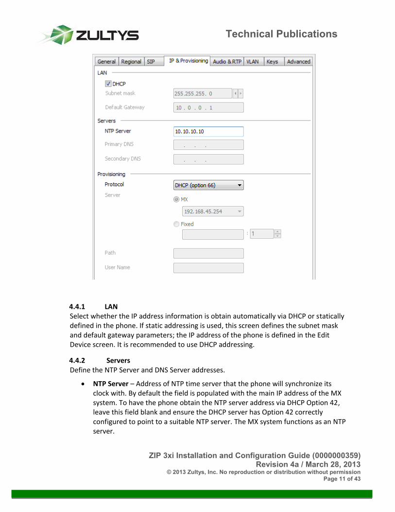
4.4 IP & Provisioning Tab The IP and Provisioning tab contains settings for defining the IP address, DNS Servers, NTP Server, and Provisioning method.
ZIP 3xi Installation and Configuration Guide (0000000359) Revision 4a / March 28, 2013
© 2013 Zultys, Inc. No reproduction or distribution without permission Page 11 of 43
Technical Publications
4.4.1 LAN Select whether the IP address information is obtain automatically via DHCP or statically defined in the phone. If static addressing is used, this screen defines the subnet mask and default gateway parameters; the IP address of the phone is defined in the Edit Device screen. It is recommended to use DHCP addressing.
4.4.2 Servers Define the NTP Server and DNS Server addresses.
NTP Server – Address of NTP time server that the phone will synchronize its clock with. By default the field is populated with the main IP address of the MX system. To have the phone obtain the NTP server address via DHCP Option 42, leave this field blank and ensure the DHCP server has Option 42 correctly configured to point to a suitable NTP server. The MX system functions as an NTP server.

ZIP 3xi Installation and Configuration Guide (0000000359) Revision 4a / March 28, 2013
© 2013 Zultys, Inc. No reproduction or distribution without permission Page 12 of 43
Technical Publications
Primary DNS / Secondary DNS – Address of DNS servers. If DHCP option is selected, the DNS addresses will be obtained from DHCP server.
4.4.3 Provisioning Define the protocol that the phones use to download their configuration files. The internal DHCP server of the MX system provides Option 66 which allows all Zultys IP phones to automatically download their configuration files from the built-in TFTP/HTTP server. When using an external DHCP server, Option 66 must be configured to provide the IP address of the MX system for automatic provisioning of a new phone to function. If Option 66 is not enabled on the DHCP server, the provisioning server address must be manually configured on the phone via the web interface or phone menu, refer to Section 4.4.4 for further details.
Overview of provisioning server options:
Protocol: Select desired protocol to be used for configuration file download.
o DHCP (option 66) – Phone will obtain the TFTP server address via DHCP option 66 and then download its configuration file using TFTP. The DHCP server must have option 66 configured with the IP address of the MX system. This is the default setting.
o TFTP – When selected, the phone will download its configuration file using TFTP from the address specified in the Server section. For most applications, the Server will be set to MX. For this option to work, the phone must initially be able to locate and connect to the MX TFTP server based on DHCP option 66; alternatively the address shown in the ‘URL preview’ may be entered manually via the phone’s menu or web interface.
o FTP - When selected, the phone will download its configuration file using FTP from the address specified in the Server section. An external FTP server is required and external TFTP server option must be configured on the MX. The User Name field must be populated with the User Name and Password of the FTP account in the format username:password. For this option to work, the phone must initially be able to locate and connect to the MX TFTP server based on DHCP option 66, otherwise the Auto Provisioning URL setting on the phone must be populated manually with the text shown in the URL preview field.
o HTTP – When selected, the phone will download its configuration file using HTTP from the address specified in the Server section. For most applications, the Server will be set to MX. For this option to work, the phone must initially be able to locate and connect to the MX TFTP server

ZIP 3xi Installation and Configuration Guide (0000000359) Revision 4a / March 28, 2013
© 2013 Zultys, Inc. No reproduction or distribution without permission Page 13 of 43
Technical Publications
based on DHCP option 66; alternatively the address shown in the ‘URL preview’ may be entered manually via the telephone’s menu.
o HTTPS - When selected, the phone will download its configuration file using HTTPS from the address specified in the Server section. An external HTTPS server is required and external TFTP server option must be configured on the MX. For this option to work, the phone must initially be able to locate and connect to the MX TFTP server based on DHCP option 66; alternatively the address shown in the ‘URL preview’ may be entered manually via the telephone’s menu.
4.4.4 Manually configuring the Provisioning Server The factory default state of the phone utilizes the DHCP (Option 66) automatic provisioning method. It is strongly recommended that the Option 66 method is used to automate the provisioning process.
If the DHCP method cannot be used the phone must be manually configured with the address and protocol required to connect to the provisioning server. If the phone is factory defaulted the provisioning method is reset to DHCP (Option 66).
Setting Provisioning Server Address via the phone webpage:
1. Browse to the IP address of the phone. The IP address may be found by pressing the
Confirm key at the idle screen. 2. Enter the username ‘admin’ and the administration password, default password is
‘admin.’ 3. From the top menu select the Phone tab. 4. From the left menu select Auto Provision. 5. Populate the Server URL with the protocol and address for the provisioning server. For
example, assuming the MX system has an IP address of 192.168.1.100: o For TFTP – tftp://192.168.1.100 o For HTTP – http://192.168.1.100:8080/tftpphone o If the network has a DHCP server with Option 66 enabled but Option 66 is not
pointing at the MX System then the DHCP Active option must also be set to Off.
6. Press to accept changes. 7. Power cycle the phone and confirm that it successfully downloads its configuration file.
A simple way to confirm correct download is to adjust the Display Name field of the device in MX Administrator and confirm the screen updates accordingly.
Setting Provisioning Server Address via the Phone Menu:
ZIP 3xi Installation and Configuration Guide (0000000359) Revision 4a / March 28, 2013
© 2013 Zultys, Inc. No reproduction or distribution without permission Page 14 of 43
Technical Publications
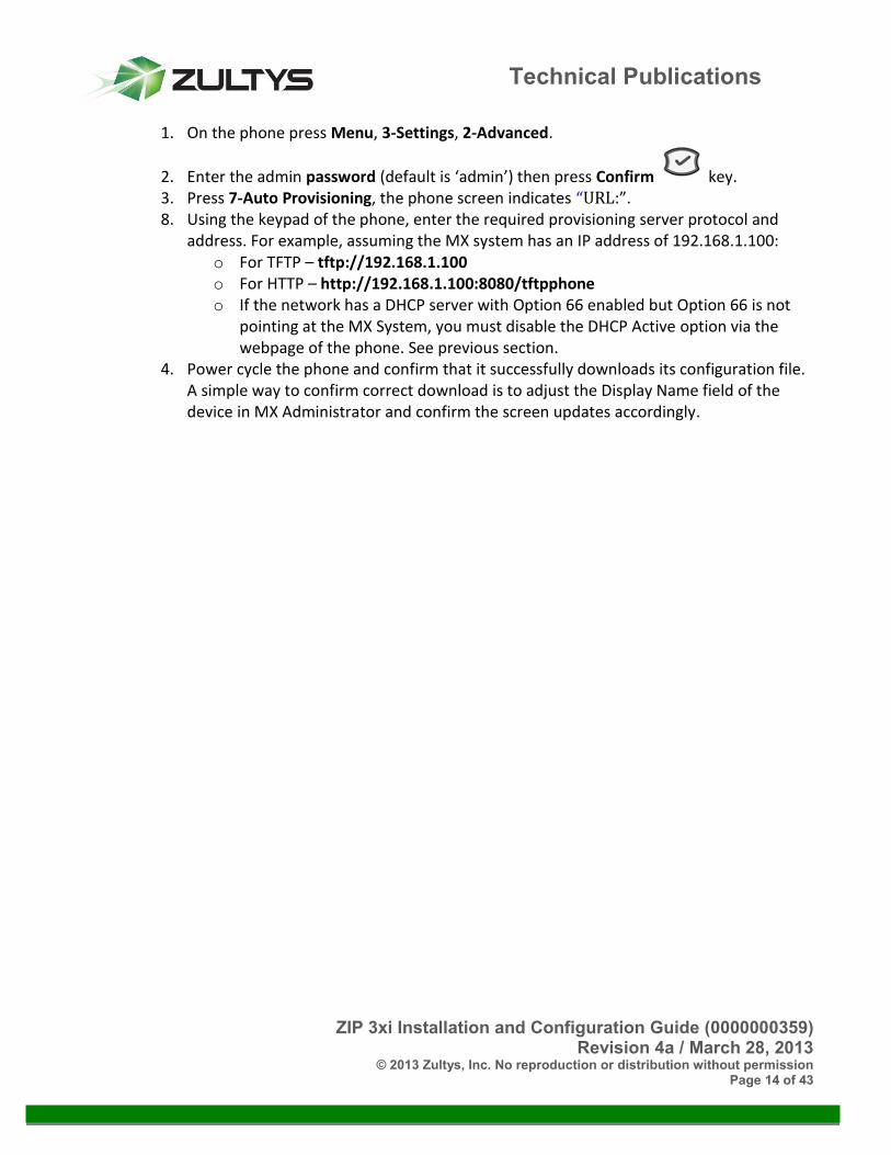
1. On the phone press Menu, 3-Settings, 2-Advanced.
2. Enter the admin password (default is ‘admin’) then press Confirm key. 3. Press 7-Auto Provisioning, the phone screen indicates “URL:”. 8. Using the keypad of the phone, enter the required provisioning server protocol and
address. For example, assuming the MX system has an IP address of 192.168.1.100: o For TFTP – tftp://192.168.1.100 o For HTTP – http://192.168.1.100:8080/tftpphone o If the network has a DHCP server with Option 66 enabled but Option 66 is not
pointing at the MX System, you must disable the DHCP Active option via the webpage of the phone. See previous section.
4. Power cycle the phone and confirm that it successfully downloads its configuration file. A simple way to confirm correct download is to adjust the Display Name field of the device in MX Administrator and confirm the screen updates accordingly.

ZIP 3xi Installation and Configuration Guide (0000000359) Revision 4a / March 28, 2013
© 2013 Zultys, Inc. No reproduction or distribution without permission Page 15 of 43
Technical Publications
4.5 Audio & RTP The Audio and RTP Tab contains setting related to DTMF, codecs, layer 3 QoS tagging, ring tones and miscellaneous settings.
4.5.1 DTMF for RTP Use the default of RFC 2833. Sending DTMF inband is not supported by the MX and should not be selected.
ZIP 3xi Installation and Configuration Guide (0000000359) Revision 4a / March 28, 2013
© 2013 Zultys, Inc. No reproduction or distribution without permission Page 16 of 43
Technical Publications
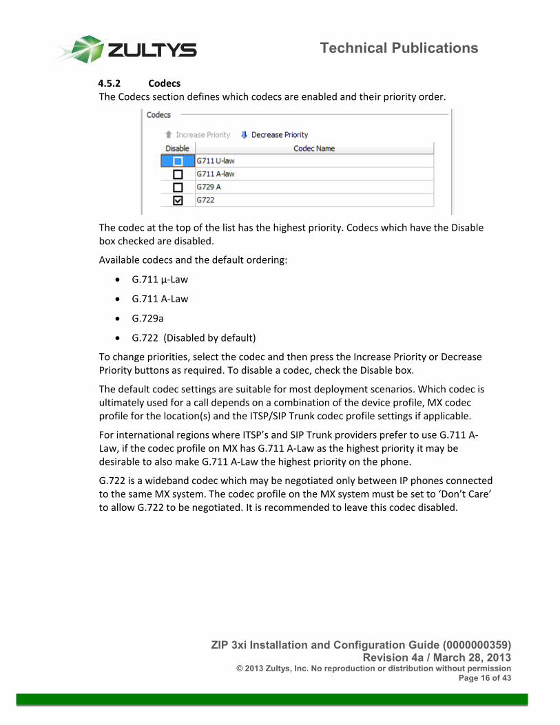
4.5.2 Codecs The Codecs section defines which codecs are enabled and their priority order.
The codec at the top of the list has the highest priority. Codecs which have the Disable box checked are disabled.
Available codecs and the default ordering:
G.711 µ-Law
G.711 A-Law
G.729a
G.722 (Disabled by default)
To change priorities, select the codec and then press the Increase Priority or Decrease Priority buttons as required. To disable a codec, check the Disable box.
The default codec settings are suitable for most deployment scenarios. Which codec is ultimately used for a call depends on a combination of the device profile, MX codec profile for the location(s) and the ITSP/SIP Trunk codec profile settings if applicable.
For international regions where ITSP’s and SIP Trunk providers prefer to use G.711 A-Law, if the codec profile on MX has G.711 A-Law as the highest priority it may be desirable to also make G.711 A-Law the highest priority on the phone.
G.722 is a wideband codec which may be negotiated only between IP phones connected to the same MX system. The codec profile on the MX system must be set to ‘Don’t Care’ to allow G.722 to be negotiated. It is recommended to leave this codec disabled.

ZIP 3xi Installation and Configuration Guide (0000000359) Revision 4a / March 28, 2013
© 2013 Zultys, Inc. No reproduction or distribution without permission Page 17 of 43
Technical Publications
4.5.3 Quality of Service: ToS/Diffserv The Quality of Service (QoS) section defines the settings for Layer 3 DSCP packet tagging.
DSCP may also be referred to as Diffserv or Type of Service (ToS) tagging. RTP and SIP packets may be tagged with different DSCP values. The underlying network must be provisioned to recognize DSCP/ToS tags and prioritize the packets accordingly.
RTP DSCP – Default value is 46 (EF)
SIP DSCP – Default value is 26 (AF31)
4.5.4 Ring Tones The Ring Tones section defines the ring tone settings and Call waiting tone.
The phone has 8 built-in ring tones and supports distinctive ringing so that the user may easily differentiate between ringing internal and external calls.
The default ring tone settings in a newly created profile are based on the Time Zone setting for the Default Location of the MX system as defined on the Provision | Locations screen, thus for most deployments the default settings are appropriate.
For US locations, Internal Calls are assigned a Ring Ring tone, and External Calls are assigned a Ring Pause tone.
For Australia, New Zealand, UK and related countries, Internal Calls are assigned a Ring Pause tone, and External Calls are assigned a Ring Ring tone.
For regions where no specific association is defined, the default settings will be the same as for the US.
4.5.5 Miscellaneous The Miscellaneous section defines settings related to Early Media support and handling of Paging calls.

ZIP 3xi Installation and Configuration Guide (0000000359) Revision 4a / March 28, 2013
© 2013 Zultys, Inc. No reproduction or distribution without permission Page 18 of 43
Technical Publications
Early Media: Select this option to enable Early Media for the phone. Early Media is a SIP mechanism that allows for inband audio to be passed through to the phone prior to the call reaching a connected state. By default this option is enabled.
Allow paging to interrupt active calls: When the phone is on an active call and a paging call is received, if this option is enabled the active call will be placed on hold and the paging call automatically answered. If disabled the active call will not be interrupted and the user must manually answer the paging call to accept it. The default setting is disabled. This option requires phone firmware version 6x.61.132.12 or later.
4.6 VLAN Tab The VLAN tab contains settings related to VLAN tagging and LLDP support.
The phone incorporates a 2 port managed switch with the ability for voice and data traffic to use different Virtual LAN’s. VLAN settings may be configured manually via the profile options or automatically using LLDP (Link Layer Discovery Protocol).
When defining the VLAN settings in the profile, care must be taken to ensure that once the phone downloads its configuration file it will be able to contact the MX system. If it cannot contact the MX system due to a mismatch between the VLAN settings stored in the phone and the configuration of the network, the phone will need to be factory reset via the Menu | Settings | Advanced | Reset Factory screen of phone.

ZIP 3xi Installation and Configuration Guide (0000000359) Revision 4a / March 28, 2013
© 2013 Zultys, Inc. No reproduction or distribution without permission Page 19 of 43
Technical Publications
4.6.1 LAN Port When VLAN support is enabled for the LAN Port, all phone related packets transmitted from the LAN port will be tagged with the defined LAN port VLAN ID and Class of Service (CoS) value.
All phone related packets received from the access network must be tagged with the same VLAN ID. Effectively this can be thought of as the Voice VLAN.
4.6.2 PC Port When VLAN support is enabled for the PC Port, untagged packets that enter the PC Port will be tagged with the defined PC port VLAN ID as they egress from the LAN port of the phone. All packets received at the LAN port which are tagged with the ID defined for the PC port, will be passed to the PC port. Effectively this can be thought of as the Data VLAN. If the Data VLAN is untagged on the access network, then this option should be disabled.
4.6.3 LLDP As an alternative to explicitly defining the VLAN ID’s for the LAN and PC ports, the Link Layer Discovery Protocol (LLDP) may be used if supported by the access switch. LLDP allows the VLAN settings to be defined at the access switch and automatically pushed to the phone.
The advantage of using LLDP is that VLAN settings are determined at power up and do not rely on parameters stored in the phone, this removes the risk of the phone downloading a configuration that is invalid for the network it is connected to.

ZIP 3xi Installation and Configuration Guide (0000000359) Revision 4a / March 28, 2013
© 2013 Zultys, Inc. No reproduction or distribution without permission Page 20 of 43
Technical Publications
When LLDP is enabled, the phone broadcasts an LLDP request on power up and then at the defined Packet Interval. The default period is ‘120 seconds.’
4.6.4 VLAN Configuration Examples The following examples relate to manually defining the VLAN settings via the Device Profile.
Tagged Voice VLAN, Untagged Data VLAN - For many deployments that use VLAN tagging, packets related to the voice VLAN will be tagged and those related to the data VLAN will be untagged and treated as part of the native VLAN by the access switch. For the configuration shown below the Voice VLAN ID is 10 and the Data VLAN is untagged.
Tagged Voice VLAN, Tagged Data VLAN – For a case where both voice and data packets are tagged as they egress and ingress at the LAN port, the phone must have VLAN’s enable for both the LAN and PC ports. For the configuration shown below the Voice VLAN ID is 10 and the Data VLAN ID is 15.

ZIP 3xi Installation and Configuration Guide (0000000359) Revision 4a / March 28, 2013
© 2013 Zultys, Inc. No reproduction or distribution without permission Page 21 of 43
Technical Publications
4.7 Keys Tab The Keys tab contains setting related to the 6 programmable keys.
The key settings defined in a device profile are applied to all phones assigned the profile. Keys settings may be modified on a per phone basis by clicking the Key Provisioning button in the Edit Device screen, see section 7.
For ZIP 35i device profiles an ‘Expansion module keys’ option will be displayed. Refer to section 0 for details on provisioning the ZIP 340M LCD expansion module.
4.7.1 Label Template The phone includes 3 pre-printed labels to cover common deployment scenarios. Select the template from the dropdown which matches the label installed on the phone. When one or more of the keys are changed from those defined by the selected template, the Label template dropdown will display Custom. Any key may be modified as required to suit the requirements of the deployment.

ZIP 3xi Installation and Configuration Guide (0000000359) Revision 4a / March 28, 2013
© 2013 Zultys, Inc. No reproduction or distribution without permission Page 22 of 43
Technical Publications
Label #1 – 3 Line keys, Page, Intercom (Factory installed label)
Label #2 – 2 Line keys, Page, Park Slots

ZIP 3xi Installation and Configuration Guide (0000000359) Revision 4a / March 28, 2013
© 2013 Zultys, Inc. No reproduction or distribution without permission Page 23 of 43
Technical Publications
Label #3 – 2 Line keys
4.7.2 Type Select the type of key. Available options are:
BLF: Defines a Busy Lamp Field (BLF) key to monitor a User or Call Group extension. Value is the extension number to monitor. Line determines the SIP registration that the BLF is associated with.
The LED will flash when the monitored extension is ringing, pressing the flashing key will pick-up the ringing call. When the monitored User is on a call the LED will be solid red. Pressing the key when the LED is off initiates a call to the defined extension number.
Prefixing the extension number value with ‘+’ will enable Hold indication on the key such that when the monitored user places a call on hold the LED will flash. Refer to KBS issue 11179 for further information about ‘+BLF’.
System wide maximums for key types that utilize BLF mechanism:
o Maximum of 500 per system.
o Maximum of 64 stations monitoring the same extension.
BLF (Monitor only): This key functions the same as ‘BLF’ with the exception of call pick-up. Pressing the key when it is flashing will not pick-up the ringing call.
o This key type is included in the BLF count for the system.
Intercom: Facilitates an intercom call to a user extension. The called phone will automatically answer (if configured to do so in the profile) and a two-way conversation is established.

ZIP 3xi Installation and Configuration Guide (0000000359) Revision 4a / March 28, 2013
© 2013 Zultys, Inc. No reproduction or distribution without permission Page 24 of 43
Technical Publications
Usage: Press key, display indicates Dial: Intercom. , enter the target extension number followed by # Send.
Line: Defines a call appearance key for a specific SIP line registration. Value is the SIP line associated with the key, for most deployments this will be 1. For example, if 3 keys are configured as Line for Line #1, the user will have 3 call appearance keys for SIP registration 1. At least one key must be configured as type Line, up to 6 keys may be configured as type Line.
Login (Call Group): Allows the defined user to log into a defined Call Group (Operator/ACD/ICC) by pressing the key. Value must be in the format of <group>.<user>, where <group> is the Call Group extension number and <user> is the extension number of the user to be logged into the Call Group. Usage: When the button is pressed, the user will be prompted to enter their voice mail password (also referred to as PIN), if the correct password is entered the call will be terminated and the LED will become solid red. Pressing the key again will log the user out of the Call Group and the LED will turn off.
o This key type is included in the BLF count for the system
Mailbox MWI: Monitors the voice mailbox of the configured extension number. Value is the extension number of the mailbox to be monitored; it may be a User or Call Group extension number. The LED is solid red when there is one or more unread voice mail messages. For user extensions only, the LED will flash when a caller is currently leaving a message; pressing the flashing LED will retrieve the caller. Pressing the key when either off or solid red, will access the associated mailbox and prompt for password.
o This key type is included in the BLF count for the system
MX Conference: Provides access to MXconference service to start or join an MXconference call. MX system must have MXconference licenses.
MXassist: Provides access to the MXassist automated attendant service which provides help to users. To use this feature an Automated Attendant with the name ‘MXassist’ must be configured on the system. Note: As at MX Release 7.2.4, this feature is under development and not yet implemented in the MX system.
None: Programmable key is disabled.
Page: Facilitates a call to a paging group. Care should be taken to ensure the number of ZIP 3xi and ZIP 5-series phones in a paging group does not exceed 32 devices on an MX250 and 16 devices on an MX30. Usage: Press key, display indicates Dial: Page. , enter the paging group number followed by # Send. After the prompt or tone begin your page.

ZIP 3xi Installation and Configuration Guide (0000000359) Revision 4a / March 28, 2013
© 2013 Zultys, Inc. No reproduction or distribution without permission Page 25 of 43
Technical Publications
Page/Intercom: Dual purpose key that facilitates a page call to a paging group or an intercom call to an extension depending upon the number entered. Refer to Page key section above for additional details about paging. Usage: Press key, display indicates the Page Server extension number (generally *4). For a paging call, enter a 2 digit paging group extension number followed by # Send. For an intercom call, enter the target user extension (must be 3 digits or longer) followed by # Send.
Park Slot (Monitored): Monitors a Park Slot, also referred to as a Park ID. In the Value field dropdown select the Park ID to monitor. When a call is currently parked at the monitored ID, the related key will flash red on all phones configured to monitor the same ID. Pressing the flashing key retrieves the parked call. When on a call, pressing the key will park the call to the associated park ID.
o This key type is included in the BLF count for the system
Prefix: The Prefix key is similar to a speed dial key, when pressed the screen will display the Prefix Value, the user may then enter additional digits followed by # Send to initiate a call to the complete number.
Speed dial: When pressed the phone initiates a call to the number/URI defined in the Value field.
4.7.3 Value Where a key requires additional parameters, such as an extension number, this is entered into the Value field. Refer to the Key descriptions above for additional information.
4.7.4 Line This parameter determines the SIP Line registration that the key is associated with. Possible selections are 1, 2 and Auto for a ZIP 33i or 1, 2, 3 or Auto for a ZIP 35i. For most deployments, the Line setting will be 1 for keys that allow selection of the line number. For keys where the Auto selection is selected, the phone will automatically select the SIP Line to use based on the call scenario. For key types Intercom, Page, Page/Intercom and Prefix the Line setting is always Auto.
4.8 Advanced Tab The Advanced tab provides a view of the data that will be stored in the device specific <MAC>.cfg file when a device is provisioned with this Device Profile. In addition, the screen provides the ability to add custom configuration data for phone options that are not exposed in the Device Profile GUI. Custom configuration data must be entered with the correct syntax including section headings. Parameters entered in the Custom screen will generally over-ride the same parameter defined in the system generated

ZIP 3xi Installation and Configuration Guide (0000000359) Revision 4a / March 28, 2013
© 2013 Zultys, Inc. No reproduction or distribution without permission Page 26 of 43
Technical Publications
configuration data. In the event that custom settings are required Zultys Technical Support will advise the correct format for the settings.
ZIP 3xi Installation and Configuration Guide (0000000359) Revision 4a / March 28, 2013
© 2013 Zultys, Inc. No reproduction or distribution without permission Page 27 of 43
Technical Publications
5 Overview of ZIP 340M Expansion Module The ZIP 35i phone may be deployed with ZIP 340M Expansion Modules. You can connect from one to six ZIP 340M Expansion Modules to each ZIP 35i phone. Each ZIP 340M supports up to 38 LCD labeled programmable keys. The keys may be configured as 2 pages by 19 keys or 1 page by 20 keys.
The ZIP 340M supports the same key Types as the 6 programmable keys located on the ZIP 33i/ZIP 35i phones with the addition of a configurable label for each key. The only exception is the key type of Line where the label will always show the Screen Name or Device ID if no Screen Name is defined.
One key type that is unique to the ZIP 340M is ‘Switch’ which can be configured for Key 1 to enable the second page of keys. Pressing the ‘Switch’ key toggles between List 1 and List 2 with each page supporting up to 19 programmable keys.
Refer to section 4.7.2 for a detailed explanation of the key types that are common with the 6 programmable phone keys and the appropriate settings for Value and Line of each type.Note: System-wide limits apply to the total number of keys that may utilize BLF functionality on an MX system. It is recommended to not provision more than 50 keys that utilize BLF functionality on a ZIP 35i phone with 2 or more ZIP 340M Expansion Modules connected.
5.1 Powering ZIP 340M Expansion Modules When 1 or 2 x ZIP 340M’s are connected to a ZIP 35i, all items may be powered via the phone either using Power over Ethernet (PoE) or an AC adapter.
When 3 or more ZIP 340M modules are connected to a ZIP 35i, the expansion modules must be powered via external AC adapter.
5.2 Using ZIP 340M’s and EHS 3xi Electronic Hook Switch Adapter together The EHS 3xi Electronic Hook Switch Adapter may be used together with a ZIP 340M. When used together the EHS 3xi must be connected to the ‘Ext Out’ port of the last ZIP 340M in the chain. Refer to section 6 for additional details regarding EHS 3xi.
5.3 Provisioning ZIP 340M Expansion Modules To provision one or more ZIP 340M Expansion Modules select the ‘Expansion module keys’ button located under the Keys tab of ZIP 35i Device Profile. Place a check mark in the Enable box for the necessary number of modules.

ZIP 3xi Installation and Configuration Guide (0000000359) Revision 4a / March 28, 2013
© 2013 Zultys, Inc. No reproduction or distribution without permission Page 28 of 43
Technical Publications
Once a module is enabled, clicking on the module in the top section of the screen will display the key settings in the bottom section of the screen.
The Expansion Module key settings defined in a device profile are applied to all phones with this profile assigned. Expansion Module key settings may be modified on a per phone basis by clicking the Key Provisioning button in Edit Device screen, see section 7.

ZIP 3xi Installation and Configuration Guide (0000000359) Revision 4a / March 28, 2013
© 2013 Zultys, Inc. No reproduction or distribution without permission Page 29 of 43
Technical Publications
6 EHS 3xi Electronic Hook Switch Adapter The ZIP 35i phone is compatible with the Zultys EHS 3xi Electronic Hook Switch Adapter. When used with a compatible wireless headset the EHS 3xi allows ZIP 35i users to answer and terminate calls using the answer button on the wireless headset
RJ12 Socket RJ45 & 3.5mm Sockets
The EHS 3xi supports various Plantronics and GN Netcom/Jabra brand wireless headsets, the connectors used on the adapter vary depending upon the brand of wireless headset used.
The RJ12 socket is always connected to the EXT Port of the ZIP 35i or to the EXT OUT Port of the last ZIP 340M Expansion Module if the ZIP 35i has 1 or more Expansion Modules connected. The 3.5mm socket is used with Plantronics headsets.
The RJ45 socket is used with GN Netcom/Jabra headsets.
There are no configuration changes required on the ZIP 35i phone as the phone automatically detects when an EHS 3xi is connected on power up.
Please refer to the sections on the following pages for more detailed information regarding how to connect specific brands of headset.
Note: The ZIP 33i phone does not support EHS and is not compatible with the EHS 3xi adapter.
ZIP 3xi Installation and Configuration Guide (0000000359) Revision 4a / March 28, 2013
© 2013 Zultys, Inc. No reproduction or distribution without permission Page 30 of 43
Technical Publications
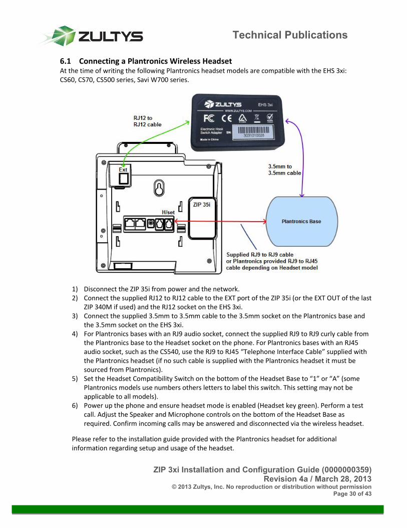
6.1 Connecting a Plantronics Wireless Headset At the time of writing the following Plantronics headset models are compatible with the EHS 3xi: CS60, CS70, CS500 series, Savi W700 series.
1) Disconnect the ZIP 35i from power and the network. 2) Connect the supplied RJ12 to RJ12 cable to the EXT port of the ZIP 35i (or the EXT OUT of the last
ZIP 340M if used) and the RJ12 socket on the EHS 3xi. 3) Connect the supplied 3.5mm to 3.5mm cable to the 3.5mm socket on the Plantronics base and
the 3.5mm socket on the EHS 3xi. 4) For Plantronics bases with an RJ9 audio socket, connect the supplied RJ9 to RJ9 curly cable from
the Plantronics base to the Headset socket on the phone. For Plantronics bases with an RJ45 audio socket, such as the CS540, use the RJ9 to RJ45 “Telephone Interface Cable” supplied with the Plantronics headset (if no such cable is supplied with the Plantronics headset it must be sourced from Plantronics).
5) Set the Headset Compatibility Switch on the bottom of the Headset Base to “1” or “A” (some Plantronics models use numbers others letters to label this switch. This setting may not be applicable to all models).
6) Power up the phone and ensure headset mode is enabled (Headset key green). Perform a test call. Adjust the Speaker and Microphone controls on the bottom of the Headset Base as required. Confirm incoming calls may be answered and disconnected via the wireless headset.
Please refer to the installation guide provided with the Plantronics headset for additional information regarding setup and usage of the headset.

ZIP 3xi Installation and Configuration Guide (0000000359) Revision 4a / March 28, 2013
© 2013 Zultys, Inc. No reproduction or distribution without permission Page 31 of 43
Technical Publications
6.2 Connecting a GN Netcom/Jabra Wireless Headset At the time of writing the following Jabra headset models are compatible with the EHS 3xi: PRO 9400 Series, GO 6470, PRO 920, GN9350e, GN9330e, GN9120 EHS.
1) Disconnect the ZIP 35i from power and the network. 2) Connect the supplied RJ12 to RJ12 cable to the EXT port of the ZIP 35i (or the EXT OUT of the last
ZIP 340M if used) and the RJ12 socket on the EHS 3xi. 3) Connect the supplied RJ45 to RJ45 cable to the RJ45 socket on the GN Netcom / Jabra base and
the RJ45 socket on the EHS 3xi. 4) Connect the supplied RJ9 to RJ9 curly cable from the GN Netcom / Jabra base to the Headset
socket on the phone. 5) The headset base should be set to DHSG mode and A on the slider bar before powering on the
phone. Note: these settings may vary between headset models. 6) Power up the phone and ensure headset mode is enabled (Headset key green). Perform a test
call. Adjust the Microphone control on the Headset Base as required. Confirm incoming calls may be answered and disconnected via the wireless headset.
Refer to the installation guide provided with the GN Netcom / Jabra headset for additional information regarding setup and usage of the headset.

ZIP 3xi Installation and Configuration Guide (0000000359) Revision 4a / March 28, 2013
© 2013 Zultys, Inc. No reproduction or distribution without permission Page 32 of 43
Technical Publications
7 Adding a Device Once a ZIP 3xi Device Profile has been created, one or more phones may be provisioned on the MX system.
To add a ZIP 3xi Device (phone) in MX Administrator:
1. Select Configure | Devices or click the Managed Devices icon .
2. Right click in the Managed Devices screen and select Insert, alternatively press the Insert key on keyboard.
3. In the New Device screen set the Device Type to ZIP 33i or ZIP 35i as required and click Next. The Add multiple devices option allows for multiple phones to be added via a list of MAC addresses. This document only covers the Add single device process.
4. In the New Device screen, select the Profile, Default Location and enter the MAC Address of the phone being provisioned. The Device ID by default will be set to the MAC address, uncheck Use MAC if an alternative Device ID is to be used. The Screen Name will be displayed on the idle screen of the phone, if left blank the Device ID will be displayed.

ZIP 3xi Installation and Configuration Guide (0000000359) Revision 4a / March 28, 2013
© 2013 Zultys, Inc. No reproduction or distribution without permission Page 33 of 43
Technical Publications
5. SIP Proxy Password: If the phone is to be deployed externally, a SIP Proxy Password must be set; the same password must be manually entered into the phone either via the Telephone User Interface (TUI) or the phones webpage. Once the phone has downloaded its configuration file perform the following steps to store the SIP password in the phone:
a. Via phone user interface: Press Menu, 3-Settings, 2-Advanced, enter admin password for phone (default is ‘admin’), 1-Accounts, select line to configure (usually Line 1), then press the Confirm key, scroll down with the arrow button to ‘Password,’ type in SIP password and press Confirm to accept, press Menu multiple times until you are back at the idle screen.
b. Via web interface: Obtain the IP address of phone by pressing the Confirm key while phone is displaying Idle screen. Browse to the IP address of phone. Select Account tab, from the Account dropdown select the Account to be edited (usually Account 1). In the Password field enter the SIP password. Press Confirm at the bottom of the screen to save the setting.
ZIP 3xi Installation and Configuration Guide (0000000359) Revision 4a / March 28, 2013
© 2013 Zultys, Inc. No reproduction or distribution without permission Page 34 of 43
Technical Publications
6. Key provisioning: If the Programmable Key settings defined in the Device Profile are to be customized for this device, click Key provisioning and adjust the key settings as required.
7. Advanced Options: The Advanced Options screen allows custom configuration data to be added to the device specific configuration file. Generally there is no requirement to do so.
8. Click Finish then Apply to save the device configuration information to the MX system. The <MAC>.cfg file will be automatically created and stored on the TFTP server.
9. Depending on the Provisioning option selected (refer to section 4.4.3) and network configuration, when the phone is connected to the network and powered up it will automatically download its configuration file and register.
8 Fixed function keys To facilitate easy access to common functions, the ZIP 3xi phones have a variety of function keys. A brief explanation of these keys appears below. Please refer to the ZIP 3xi User’s Guide for detailed information.
Menu – Access the phone features and settings menu. For the ZIP 35i this is soft key #1.
DND – Enable / Disable Do Not Disturb. When enabled, any call offered to the phone will be rejected with a 486 BUSY response. For the ZIP 35i, this is soft key #2.
Park / Pickup – Access the Park/Pickup feature. Pressing the Park key during an active call, results in the call being parked and the system allocated Park ID being displayed on screen. Pressing the Park key when the phone is idle or off-hook but is not on an active call prompts the user to enter a Park ID to retrieve a parked call. Press # Send to initiate call after entering ID. For the ZIP 35i, this is soft key #3 and is labeled ‘Pickup’ when a call is not active and ‘Park’ when a call is active.
Directory / Dir – Provides access to the local directory stored on the phone. For the ZIP 35i, this is soft key #4 and is labeled ‘Dir’.
Call Log – Provides access to the call log of the phone. When pressed the “All calls” list is displayed, left and right cursor keys switch between all, missed, inbound, outbound and forwarded call logs.
X / End Call – When a call is active pressing this key disconnects the call. The key also acts as a delete key when entering information and a cancel or back key during menu operations.

ZIP 3xi Installation and Configuration Guide (0000000359) Revision 4a / March 28, 2013
© 2013 Zultys, Inc. No reproduction or distribution without permission Page 35 of 43
Technical Publications
Message – Provides access to the voice mail service of the MX system. Also acts as Message Waiting Indicator (MWI). Key is illuminated green when one or more unread voice mail messages are available for the user. The red status LED of the phone will also flash when an unread voice mail message is present.
Headset – Enables headset mode. When illuminated green the headset mode is active and calls answered via the line keys or MXIE will utilize the headset. In addition, pressing the key while an incoming call is ringing will answer the call and route the audio to the headset. Optional headset must be connected. The ZIP 35i phone supports Electronic Hook Switch when used with the ‘EHS 3xi Electronic Hook Switch Adapter’ and compatible wireless headset.
Conference – Facilitates setup of local 3 way conference calls. Usage: Press Conference during an active call. The call will be placed on hold. Enter the number of the second party and then press # Send. Press Conference again when the second party answers. All parties are now joined in the conference. Note: To conference two existing calls, place one call on hold then press Conference while the other call is active.
Hold – When a call is active, pressing this key places the call on hold. Press again to retrieve call.
Mute – Enable/disable the microphone during an active call.
Transfer – Facilitates call transfer operations. Usage:
o Blind Transfer: Press Transfer during an active call. The call is placed on hold. Enter the number you want to transfer to. Press Transfer.
o Attended Transfer: Press Transfer during an active call. The call is placed on hold. Enter the number you want to transfer to and then press # Send. Press Transfer when ready to complete the transfer or X key to cancel transfer.
Redial – Facilitates redialing of recently called numbers. Usage: Press Redial to enter the Dialed Calls list, press Up or Down keys to select the desired call and then press Redial or # Send. To access other areas of the Call History use Left and Right keys. Press Redial twice when the phone is idle to call the last dialed number.
Speaker – Press the Speaker key when a call is ringing to answer in handsfree mode.
ZIP 3xi Installation and Configuration Guide (0000000359) Revision 4a / March 28, 2013
© 2013 Zultys, Inc. No reproduction or distribution without permission Page 36 of 43
Technical Publications
9 Controlling Configurations
9.1 Configuration methods The ZIP 3xi phones may be configured via the following methods:
As a managed device in MX Administrator (The method detailed in this document)
Web interface of phone
Menu of phone
Provisioning a phone as a managed device on the MX system automatically generates a configuration file on the MX’s TFTP server with the name <MAC>.cfg. For example, for phone with MAC address 000BEA81B8B8, the filename is 000bea81b8b8.cfg.
Any manual configuration changes performed via the web interface or the menu of the phone will take precedence over the configuration options defined in the configuration file downloaded from the MX TFTP server.
If a phone has been manually configured via the web interface or phone menu, the phone must be Factory Reset to fully restore automatic provisioning. Refer to section 11.1.
9.2 Phone Initialization Upon power-up a new or un-configured phone will initialize as follows:
Request IP address and Option 66 (TFTP server address) from DHCP server.
Depending on model request zip33i_common.cfg or zip35i_common.cfg file from TFTP server.
Request <MAC>.cfg file from TFTP server.
Request new firmware ROM image file from TFTP server if defined in cfg file.
Complete power-up and register with MX system based on settings defined in cfg files.
The zip33i_common.cfg and zip35i_common.cfg files referred to above may be used to apply custom configuration settings to all ZIP 33i and ZIP 35i phones connected to an MX system. Generally there is no requirement to use these files.
10 Upgrading Firmware
10.1 Upgrading firmware via Device Profile When a ZIP 3xi phone is provisioned as a managed device via MX Administrator, the firmware version of the phone is determined by the Firmware filename defined in the Device Profile. The corresponding firmware ROM file must be uploaded to the TFTP server of the MX system.

ZIP 3xi Installation and Configuration Guide (0000000359) Revision 4a / March 28, 2013
© 2013 Zultys, Inc. No reproduction or distribution without permission Page 37 of 43
Technical Publications
Firmware ROM files are available for download from the Zultys Knowledge Base System (http://kbs.zultys.com).
To upgrade/change the firmware version of a ZIP 3xi phone perform the following steps:
1. From Configure | Devices screen press the button.
2. Copy the <version>.rom file to the TFTP server. Press Close. Note: All ZIP 33i firmware image files have the format 60.x.x.x.rom (For example, 60.61.132.12.rom); all ZIP 35i firmware image files have the format 65.x.x.x.rom (For example, 65.61.132.15.rom).
3. Open the Device Profile associated with the Device that is to be updated.
4. In the filename field located in the General tab, select the filename of file uploaded in step 2.
5. Press OK then Apply to save changes to MX.
6. Select the device to be updated from the device list. Multiple devices may be selected via standard Windows Shift+Click and Ctrl+Click keyboard controls.
7. Click the button to send the update request to each phone that is currently registered to the MX system.
8. Alternatively, power cycle or power up each phone to trigger a firmware update.
9. Once complete the firmware version may be checked via the User Agent field of View |
Device Status screen.

ZIP 3xi Installation and Configuration Guide (0000000359) Revision 4a / March 28, 2013
© 2013 Zultys, Inc. No reproduction or distribution without permission Page 38 of 43
Technical Publications
10.2 Upgrading firmware via Web interface For cases where the phone is not provisioned as a managed device or cannot access the TFTP server, the firmware may be updated via the phones web interface.
To upgrade the firmware via the web interface of phone perform the following steps:
1. Browse to the IP address of the phone. The IP address may be found by pressing the Confirm key at the idle screen.
2. Enter the username ‘admin’ and the administration password, default password is ‘admin.’
3. From the top menu select the Phone tab.
4. From the left menu select Upgrade.
5. Select Browse and browse to the ROM file, then select Open.
6. Select Upgrade. To proceed with upgrade press OK on the warning popup.
7. Do not disconnect power or exit webpage until the phone has restarted.
8. Once the upgrade is complete, the webpage will be refreshed (assuming the IP address of the phone has not changed during restart).
9. The current firmware version is displayed on the Phone | Upgrade webpage and also on the Status webpage.
Note that if after the upgrade the phone downloads a configuration file that defines a different firmware version, the phone will immediately upgrade to the version defined in the configuration file.
Warning: Once the download process for the new firmware starts you must not disconnect power or restart the phone. If the process is interrupted, the phone will lose all firmware and the emergency recovery process will need to be performed. Contact your Authorized Zultys Channel Partner or Zultys Technical Support should this situation arise.

ZIP 3xi Installation and Configuration Guide (0000000359) Revision 4a / March 28, 2013
© 2013 Zultys, Inc. No reproduction or distribution without permission Page 39 of 43
Technical Publications
11 Troubleshooting Tips and Tools
11.1 Factory resetting phone Should an invalid configuration be downloaded to or set on the phone it may be necessary to perform a factory reset. Resetting the phone to factory defaults removes all configuration settings from the phone including those applied via the web interface and menu of the phone.
Steps to Factory Reset a phone:
Method 1:
1. Press and hold the Confirm key for 10 seconds until “Reset to Factory” is displayed. Release the key.
2. Press the Confirm key to proceed with Factory Reset.
Method 2:
1. Press Menu.
2. Select 3-Settings.
3. Select 2-Advanced.
4. Enter Admin password. Default password is ‘admin.’
5. Select 4-Reset Factory.
6. The screen will display Reset to Factory? , press the Confirm key to proceed with reset. Screen will display Please wait Reset. .
7. The phone will now perform initialization per section 9.2.
11.2 Rebooting phone Should the need to arise to reboot / restart the phone this may be done using the following method.
1. Press and hold the X / End Call key for 10 seconds until “Warning Reboot?” is displayed. Release the key.
2. Press the Confirm key to proceed with Reboot.

ZIP 3xi Installation and Configuration Guide (0000000359) Revision 4a / March 28, 2013
© 2013 Zultys, Inc. No reproduction or distribution without permission Page 40 of 43
Technical Publications
A reboot does not change any configuration settings on the phone and is effectively equivalent to power cycling the phone. The phone will attempt to re-download its configuration settings from the TFTP server if it is configured for automatic provisioning.
11.3 Phone does not use the configuration file on TFTP server If the ZIP 3xi phone does not use the configuration file, or some settings defined in the configuration file do not appear to be used, check the following:
Make sure you have not previously configured the phone using the web interface or the phone interface. Any option manually configured from the web interface or the phone interface will take precedence over the values contained in the configuration file downloaded from the TFTP server.
Make sure the MAC address defined in MX Administrator matches the MAC address of the phone. To check the MAC on the phone, press the Confirm button while the idle screen is displayed, then press the Down arrow to display MAC address.
Confirm the DHCP Server is providing the IP address of the TFTP server in Option 66. If Option 66 is not being used, the phone must be manually configured with the provisioning server address.
Phone was previously configured via the web or phone interface.
o Reset the phone to factory defaults and configure using a configuration file from the MX.
11.4 How to check if configuration file is downloaded A simple way to confirm if a phone is downloading its configuration file is to change the Screen Name set in the Edit Device screen. Apply the change then power cycle the phone. If the screen name displayed on the phone changes to the new value defined via MX Administrator then the phone is correctly downloading the configuration file from the MX system.
11.5 Performing a network packet capture using the phone The ZIP 3xi phones have the ability to perform a packet capture in “pcap” format which is compatible with Wireshark. To facilitate a packet capture, perform the following steps:
1. Browse to the IP address of the phone. The IP address may be found by pressing the
Confirm key at the idle screen.
2. Enter the username ‘admin’ and the administration password, the default password is ‘admin’.
3. From the top menu select the Phone tab.

ZIP 3xi Installation and Configuration Guide (0000000359) Revision 4a / March 28, 2013
© 2013 Zultys, Inc. No reproduction or distribution without permission Page 41 of 43
Technical Publications
4. From the left menu select Upgrade.
5. In the PCAP Trace section click .
6. To stop the packet capture click .
7. To export the captured information click and save the file to an appropriate location.
8. The file may now be opened in Wireshark or similar packet analysis applications.
11.6 Capturing Syslog information The ZIP 3xi phones have the ability to generate Syslog information that may assist Zultys Technical Support with investigation of issues. This information may be stored locally on the phone or output to an external Syslog server. If instructed to do so, you may enable the Syslog feature by one of the following methods:
11.6.1 Capturing Syslog information locally on phone 1. Browse to the IP address of the phone. The IP address may be found by pressing the
Confirm key at the idle screen.
2. Enter the username ‘admin’ and the administration password, default password is ‘admin.’
3. From the top menu select the Phone tab.

ZIP 3xi Installation and Configuration Guide (0000000359) Revision 4a / March 28, 2013
© 2013 Zultys, Inc. No reproduction or distribution without permission Page 42 of 43
Technical Publications
4. From the left menu select Configuration.
5. Set Export System Log option to Local.
6. Set SystemLogLevel to the value requested by Zultys Technical Support. The higher the number, the more detailed the information captured.
7. Press to accept changes.
8. To save stored events click and select a location to save file to.
11.6.2 Enabling Syslog output to external server via web interface This setup requires an external syslog server; this procedure assumes that the system administrator has set up a suitable syslog server.
1. Browse to the IP address of the phone. The IP address may be found by pressing the
Confirm key at the idle screen.
2. Enter the username ‘admin’ and the administration password, default password is ‘admin.’
3. From the top menu select the Phone tab.
4. From the left menu select Configuration.
5. Set Export System Log option to Server.
6. Enter the IP address of the external syslog server in the Server Name field.
7. Set SystemLogLevel to the value requested by Zultys Technical Support. The higher the number, the more detailed the information captured.
8. Press to accept changes.
9. The phone will now send Syslog messages to the configured Syslog server address.
11.6.3 Enabling Syslog output to external server via configuration file This setup requires an external syslog server; this procedure assumes that the system administrator has setup a suitable syslog server.
1. Create a new Device Profile to be used by the phone that is being tested. Generally, the easiest way to do this is by creating a duplicate of the current profile.
2. In the Advanced tab of the Profile select Custom configuration data.

ZIP 3xi Installation and Configuration Guide (0000000359) Revision 4a / March 28, 2013
© 2013 Zultys, Inc. No reproduction or distribution without permission Page 43 of 43
Technical Publications
3. Enter the following custom configuration parameters - [ cfg:/phone/config/system.ini,reboot=0 ]
SYSLOG.SyslogdIP = 192.168.1.100
[ cfg:/phone/config/user.ini,reboot=0 ]
PhoneSetting.LogLevel = 5
Replace the IP address with the address of your external Syslog server. Set the LogLevel to a value between 1 and 6 as advised by Zultys Technical Support.
4. Press OK then Apply to accept the Profile changes.
5. Assign the Profile to the device you want to test.
6. Select the device in the device list and press Update to trigger the phone to download the new configuration file.
7. The phone will now send Syslog messages to the configured Syslog server address.
Once the required syslog information is captured, the phone should be returned to the default settings of Local and Level 3.
12 Emergency Recovery Mode In the event that the phone is unable to initialize, following a failed firmware upgrade due to power loss or a similar problem, it may be possible to use the Emergency Recovery Mode to reload the firmware.
For assistance with this process please contact your Zultys Authorized Channel Partner or Zultys Technical Support.


![Index [182.160.97.198:8080]](https://static.fdocuments.in/doc/165x107/618107c6ef86d83c916e82c4/index-182160971988080.jpg)