13 Gunn Effect Amplifiers - University of South Carolinaee.sc.edu/personal/faculty/simin/ELCT882/13...
19
13 Gunn Effect Amplifiers I. Stable Gunn Diodes: I-V Characteristics If the sample parameters do not meet the Kroemer criteria, the sample is stable, i.e. the high-field domains do not form. However, the differential mobility is still negative at high electric fields. In this case, 1. What is the I-V characteristic of the sample? 2. How does the negative mobility change the device impedance?
Transcript of 13 Gunn Effect Amplifiers - University of South Carolinaee.sc.edu/personal/faculty/simin/ELCT882/13...

13 Gunn Effect Amplifiers
I. Stable Gunn Diodes: I-V Characteristics
If the sample parameters do not meet the Kroemer criteria,
the sample is stable, i.e. the high-field domains do not form.However, the differential mobility is still negative at high electric fields.In this case,1. What is the I-V characteristic of the sample?2. How does the negative mobility change the device impedance?

12 Gunn Effect Amplifiers
I. Stable Gunn Diodes: I-V Characteristics
Regular “ohmic” n-sample with n+ contacts.
An average field in the sample:
Anode
F
n(x)
DistanceCathode
The current density in the sample is constant:
Therefore, when n(x) decreases, F(x) increases

12 Gunn Effect Amplifiers
I. Stable Gunn Diodes: I-V Characteristics
Expected I-V curve: I = qS n0 v(F)
If the electric field is uniform, F = U/L and
I = qS n0 v(U/L)
v(F)
F
I
V

12 Gunn Effect Amplifiers
I. Stable Gunn Diodes: I-V Characteristics
v(F)
F
FP
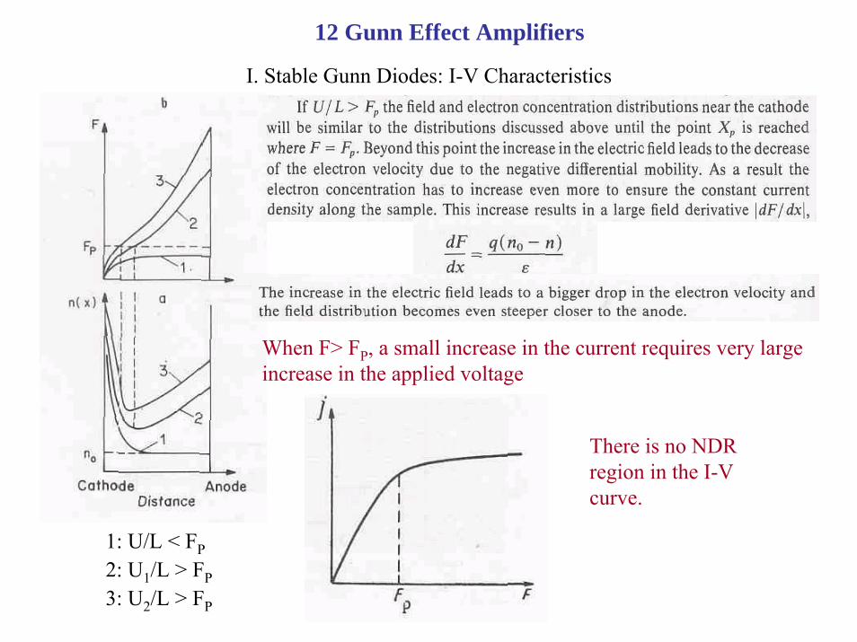
Neglecting the diffusion and correspondingly the boundary condition at the anode contact, the field distribution can be obtained from Poisson and current continuity equations:
1: U/L < FP2: U1/L > FP3: U2/L > FP
12 Gunn Effect Amplifiers
I. Stable Gunn Diodes: I-V Characteristics
1: U/L < FP2: U1/L > FP3: U2/L > FP
When F> FP, a small increase in the current requires very large increase in the applied voltage
There is no NDR region in the I-V curve.

12 Gunn Effect Amplifiers
II. Stable Gunn Diodes: device impedance

12 Gunn Effect Amplifiers
II. Stable Gunn Diodes: device impedance
To find the device impedance we will solve two equations:
One obvious solution to them is the “DC” one:

12 Gunn Effect Amplifiers
II. Stable Gunn Diodes: device impedance
To find the device impedance we will seek the solution in the form of small sinusoidal signals:
Substituting F(x,t) and n(x,t) gives the following dispersion equation (i.e. the solution for non-zero n1 and F1)

12 Gunn Effect Amplifiers
The wavelength (the characteristic size of the fluctuation) λ is related to the wave vector:
see:
Frequency Attenuation
12 Gunn Effect Amplifiers
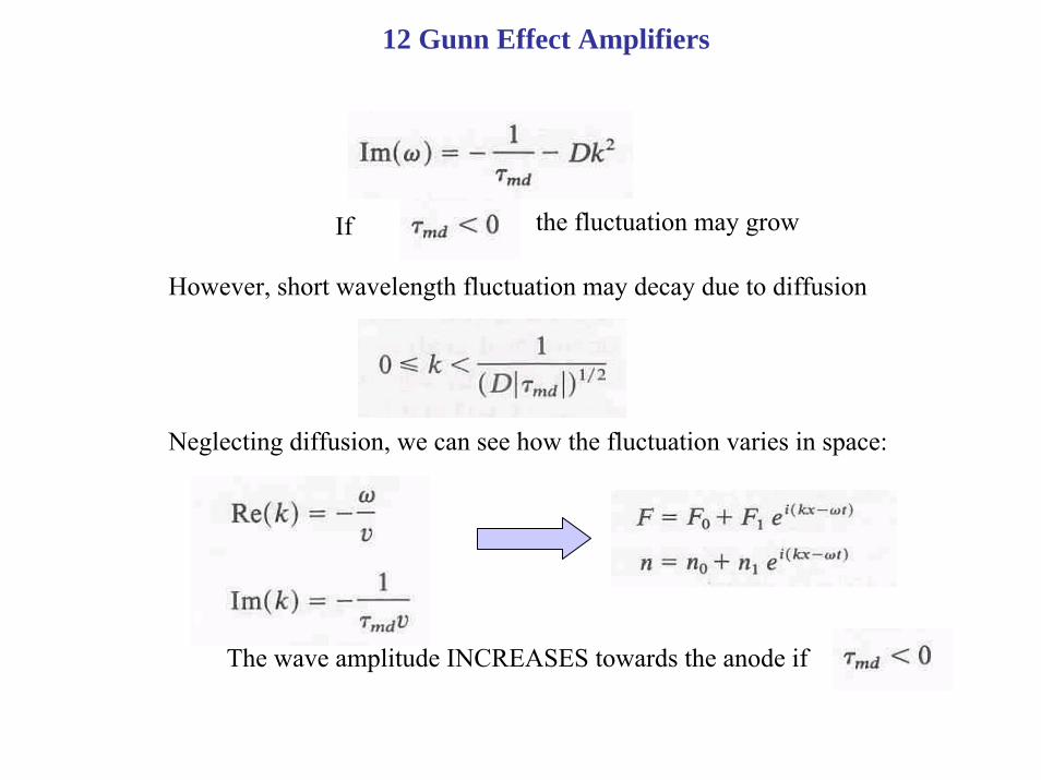
If the fluctuation may grow
However, short wavelength fluctuation may decay due to diffusion
Neglecting diffusion, we can see how the fluctuation varies in space:
The wave amplitude INCREASES towards the anode if

12 Gunn Effect Amplifiers
Gunn-effect GaAs traveling wave amplifier

12 Gunn Effect Amplifiers
To fine the impedance let us again seek the small-signal solution neglecting diffusion:
At the cathode (x=0),
Hence,
It then follows from above

12 Gunn Effect Amplifiers
Small-signal impedance:
Using we obtain:
where

12 Gunn Effect Amplifiers
Using
we can plot the diode impedance. However this expression does not account for (i) non-uniform field distribution and (ii) diffusion.
More accurate results (dashed lines – neglecting the diffusion; solid lines – including the diffusion):

12 Gunn Effect Amplifiers
where
Is the sample stable?
If the diode is biased from the current source, then j1 = 0.
U1 ≠0 only if Z(ω) -> ∞
However, the impedance does not have poles (α2 ≠ 0):
If the diode is biased from the voltage source, then U1 = 0.
j1 ≠ 0 only if Z(ω) =0, or
12 Gunn Effect Amplifiers
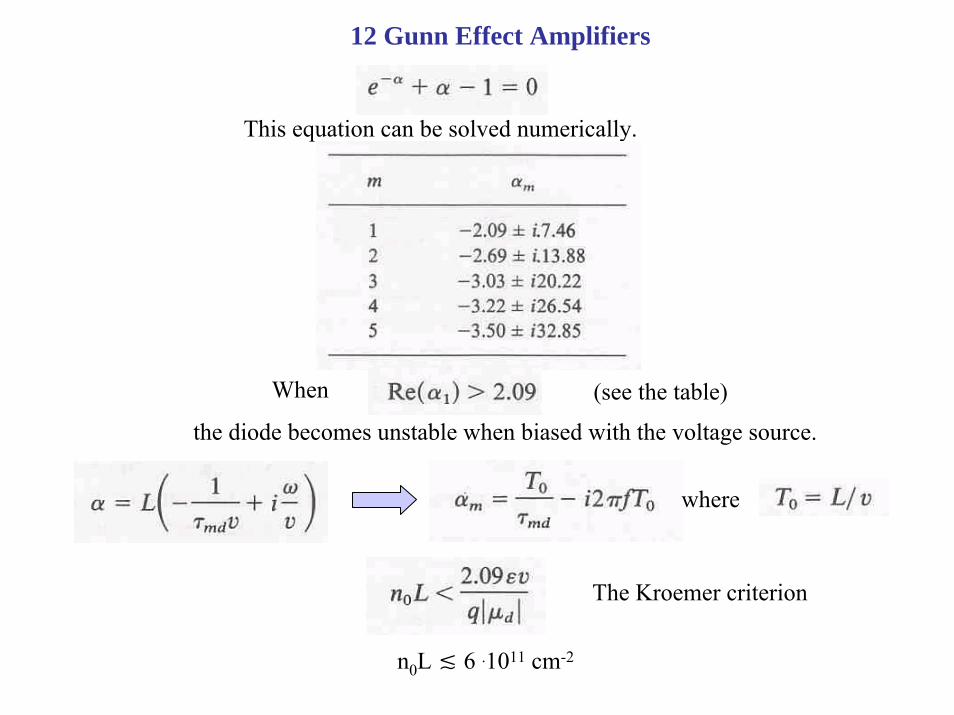
This equation can be solved numerically.
When (see the table)
the diode becomes unstable when biased with the voltage source.
where
The Kroemer criterion
n0L 6 .1011 cm-2

12 Gunn Effect Amplifiers
Traveling wave (active medium) propagation amplifier

12 Gunn Effect Amplifiers
Reflection type amplifier
If
the gain is bigger then unity.
12 Gunn Effect Amplifiers
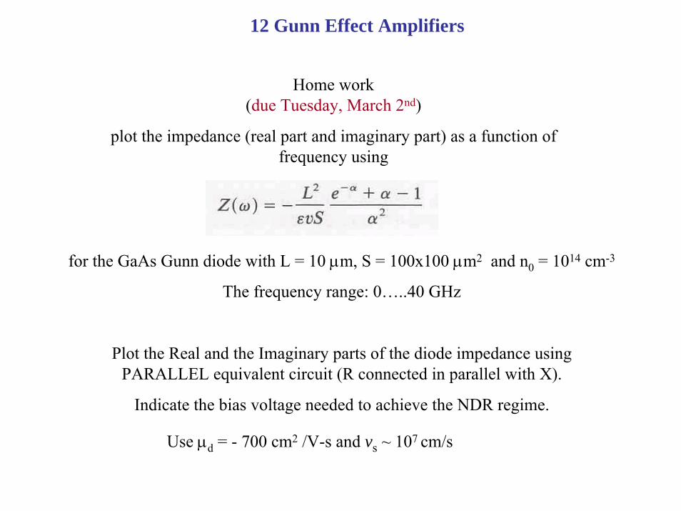
Home work (due Tuesday, March 2nd)
plot the impedance (real part and imaginary part) as a function of frequency using
for the GaAs Gunn diode with L = 10 µm, S = 100x100 µm2 and n0 = 1014 cm-3
The frequency range: 0…..40 GHz
Plot the Real and the Imaginary parts of the diode impedance using PARALLEL equivalent circuit (R connected in parallel with X).
Indicate the bias voltage needed to achieve the NDR regime.
Use µd = - 700 cm2 /V-s and vs ~ 107 cm/s