
13 - CRS Q500 A30 Conf Spec ENG 20130129 -...
15
Legend YY-Z: YY = Number of modules (not including header), Z = (1) Power Module, (R) Reverse Unit, (i) Intermediate Cooling Unit Order of modules is from the bottom to the top. CRS_Q500_A30_Conf_Spec_ENG_20130129 335 2 1 9 1 3 2 2 0 0 5 5 1 2 5 - 6 0 355 50 P LINE INPUT RESERVED SPACE Configuration 03-1i1 Configuration 03-Ri1 Configuration 02-i1 335 LINE INPUT RESERVED SPACE 2 0 0 1 3 2 1 3 2 2 1 9 6 8 3 355 50 P 2 5 - 6 0 LINE INPUT RESERVED SPACE 335 2 0 0 1 3 2 1 3 2 2 1 9 6 8 3 355 50 P 2 5 - 6 0 1 5 3 1 5 3 2 8 5 424 429 429 424 429 424 1 | 15
Transcript of 13 - CRS Q500 A30 Conf Spec ENG 20130129 -...

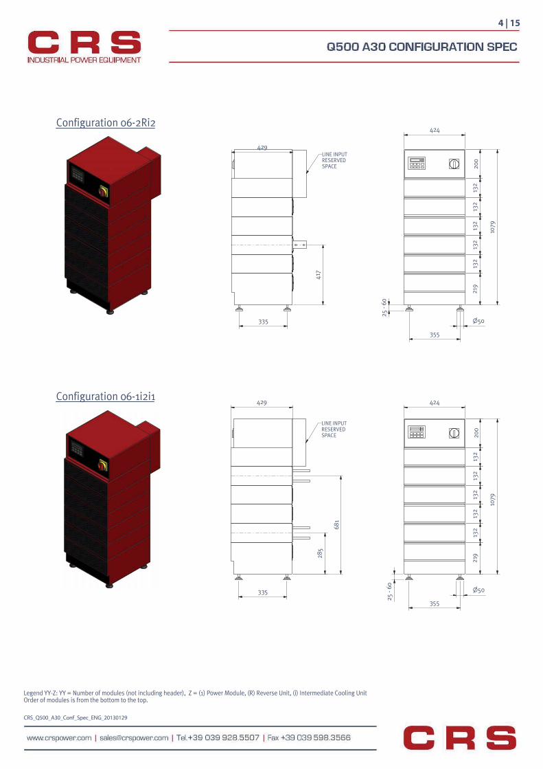
Legend YY-Z: YY = Number of modules (not including header), Z = (1) Power Module, (R) Reverse Unit, (i) Intermediate Cooling UnitOrder of modules is from the bottom to the top.
CRS_Q500_A30_Conf_Spec_ENG_20130129
335
219
132
200
551
25 -
60 35550
LINE INPUTRESERVEDSPACE
Configuration 03-1i1
Configuration 03-Ri1
Configuration 02-i1
335
LINE INPUTRESERVEDSPACE 20
013
213
221
9
683
35550
25-6
0
LINE INPUTRESERVEDSPACE
335
200
132
132
219
683
35550
25 -
60
153
153
285
424429
429 424
429 424
1 | 15

Legend YY-Z: YY = Number of modules (not including header), Z = (1) Power Module, (R) Reverse Unit, (i) Intermediate Cooling UnitOrder of modules is from the bottom to the top.
CRS_Q500_A30_Conf_Spec_ENG_20130129
Configuration 05-1i1i1
Configuration 04-1i2
335
LINE INPUTRESERVEDSPACE
355
200
132
132
219
815
50
25 -
60
LINE INPUTRESERVEDSPACE
335
355
50
25 -
60
200
132
132
947
549
429 424
429 424
Configuration 04-Ri2429
153
LINE INPUTRESERVEDSPACE
424
200
132
132
219
50
35525 -
60
335
815
2 | 15
285
132
132
219
132
132

Legend YY-Z: YY = Number of modules (not including header), Z = (1) Power Module, (R) Reverse Unit, (i) Intermediate Cooling UnitOrder of modules is from the bottom to the top.
CRS_Q500_A30_Conf_Spec_ENG_20130129
429
LINE INPUTRESERVEDSPACE
335
417
424
947
219
132
132
132
132
200
25 -
60 355
Configuration 05-2i2
429
417
335
LINE INPUTRESERVEDSPACE
424
947
219
132
132
132
132
200
25- 6
0
355
Configuration 05-1iRi1
Configuration 05-1Ri2
50
50
3 | 15
424
355
50
25 -
60
200
132
132
132
132
219
947
335
429
285
LINE INPUTRESERVEDSPACE
Legend YY-Z: YY = Number of modules (not including header), Z = (1) Power Module, (R) Reverse Unit, (i) Intermediate Cooling UnitOrder of modules is from the bottom to the top.
CRS_Q500_A30_Conf_Spec_ENG_20130129
4 | 15
50
355
25 -
60
200
132
132
132
132
132
219
1079
424
LINE INPUTRESERVEDSPACE
681
285
335
429Configuration 06-1i2i1
Configuration 06-2Ri2424
50
355
25 -
60
200
132
132
132
132
132
219
1079
335
429LINE INPUTRESERVEDSPACE
417

Legend YY-Z: YY = Number of modules (not including header), Z = (1) Power Module, (R) Reverse Unit, (i) Intermediate Cooling UnitOrder of modules is from the bottom to the top.
CRS_Q500_A30_Conf_Spec_ENG_20130129
Configuration 06-2i3
335
35525 -
60 50
219
132
132
132
132
132
200
1079
LINE INPUTRESERVEDSPACE
417
429 424
429
417
335
LINE INPUTRESERVEDSPACE
424
200
132
132
132
132
132
219
1079
355
50
25-6
0
Configuration 06-1iRi2
5 | 15

Legend YY-Z: YY = Number of modules (not including header), Z = (1) Power Module, (R) Reverse Unit, (i) Intermediate Cooling UnitOrder of modules is from the bottom to the top.
CRS_Q500_A30_Conf_Spec_ENG_20130129
Configuration 07-1iRRi2
Configuration 07-1i3i1
LINE INPUTRESERVEDSPACE
33535525
- 60
219
132
132
132
132
132
132
200
1211
50
LINE INPUTRESERVEDSPACE
335355
50
25 -
60
219
132
132
132
132
132
132
200
1211
418 54
9
285
813
429 424
429 424
6 | 15

Legend YY-Z: YY = Number of modules (not including header), Z = (1) Power Module, (R) Reverse Unit, (i) Intermediate Cooling UnitOrder of modules is from the bottom to the top.
CRS_Q500_A30_Conf_Spec_ENG_20130129
Configuration 08-2i2i2
LINE INPUTRESERVEDSPACE
335
355
50
25 -
60
200
132
132
132
132
132
132
219
1343
417
813
429 424
681
335
429
LINE INPUTRESERVEDSPACE
424
200
132
132
132
132
132
132
219
1343
355
50
25 -
60
Configuration 08-2i1Ri2
7 | 15
132
132

Legend YY-Z: YY = Number of modules (not including header), Z = (1) Power Module, (R) Reverse Unit, (i) Intermediate Cooling UnitOrder of modules is from the bottom to the top.
CRS_Q500_A30_Conf_Spec_ENG_20130129
Configuration 08-2iRRi2
Configuration 09-2i3i2
LINE INPUTRESERVEDSPACE
335
549 68
1
355
50
25 -
60
219
132
132
132
132
132
132
132
200
1343
LINE INPUTRESERVEDSPACE
33535525
- 60 50
219
132
132
132
132
132
132
132
132
200
1475
417
945
429 424
429 424
8 | 15

Legend YY-Z: YY = Number of modules (not including header), Z = (1) Power Module, (R) Reverse Unit, (i) Intermediate Cooling UnitOrder of modules is from the bottom to the top.
CRS_Q500_A30_Conf_Spec_ENG_20130129
335
355
50
25 -
60
219
132
132
132
132
132
132
132
132
200
1475
Configuration 09-2iR1Ri2
Configuration 10-2i4i2
LINE INPUTRESERVEDSPACE
549
813
LINE INPUTRESERVEDSPACE
335
355
50
25 -
60
219
132
132
132
132
132
132
132
132
132
200
1607
417
1077
429 424
429 424
9 | 15

Legend YY-Z: YY = Number of modules (not including header), Z = (1) Power Module, (R) Reverse Unit, (i) Intermediate Cooling UnitOrder of modules is from the bottom to the top.
CRS_Q500_A30_Conf_Spec_ENG_20130129
Configuration 10-2i1RR1i2
Configuration 10-2iRRRi3
335 355
50
25 -
60
219
132
132
132
132
132
132
132
132
132
200
1607
LINE INPUTRESERVEDSPACE
681 81
3
429 424
LINE INPUTRESERVEDSPACE
335
429
549 68
1 813
42425
-60
355
50
1607
200
132
132
132
132
132
132
132
132
132
219
10 | 15

Legend YY-Z: YY = Number of modules (not including header), Z = (1) Power Module, (R) Reverse Unit, (i) Intermediate Cooling UnitOrder of modules is from the bottom to the top.
CRS_Q500_A30_Conf_Spec_ENG_20130129
Configuration 11-2i2i2i2
429
1209
417
LINE INPUTRESERVEDSPACE
424
1739
200
132
132
132
132
132
132
132
132
132
219
25 -
60
Configuration 11-3i3i3
132
355
335 50
335
429
LINE INPUTRESERVEDSPACE
549
1077
50
25-6
0
355
1739
200
132
132
132
132
132
132
132
132
219
424
11 | 15
132
132
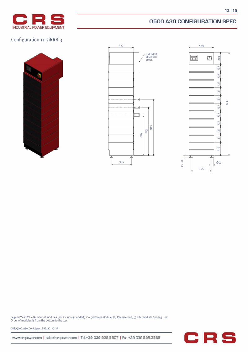
Legend YY-Z: YY = Number of modules (not including header), Z = (1) Power Module, (R) Reverse Unit, (i) Intermediate Cooling UnitOrder of modules is from the bottom to the top.
CRS_Q500_A30_Conf_Spec_ENG_20130129
Configuration 11-3iRRRi3
335
945
813
681
429
LINE INPUTRESERVEDSPACE
25 -
60
1739
219
132
132
132
132
132
132
132
132
132
132
200
424
12 | 15
50
355
DETAIL E
DETAIL M
DETAIL N
E
M
N
CRS_Q500_A30_Conf_Spec_ENG_20130129
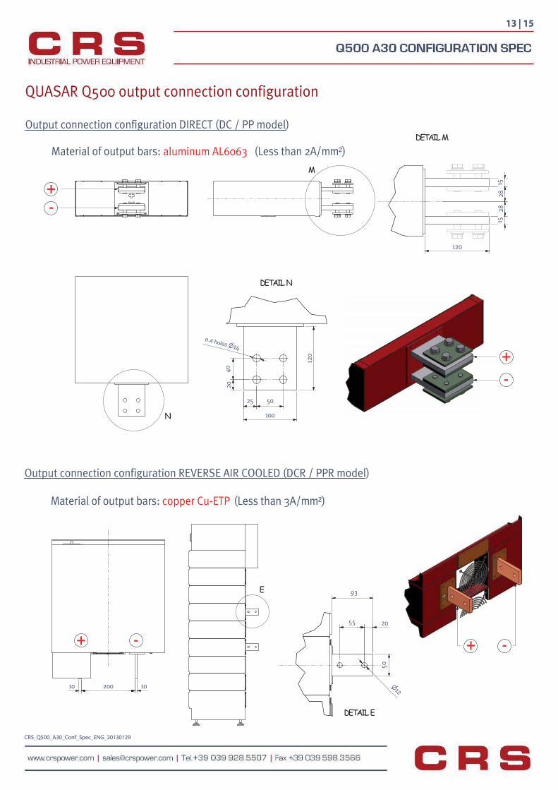
QUASAR Q500 output connection configuration
Output connection configuration DIRECT (DC / PP model)
Output connection configuration REVERSE AIR COOLED (DCR / PPR model)
55
50
20
12
93
120
1515
25 50
2040
100
120
14n.4 holes
2828
Material of output bars: (Less than 2A/mm²)
Material of output bars: (Less than 3A/mm²)
13 | 15
aluminum AL6063
copper Cu-ETP
+ -
+ -
10 200 10
+ - + -

DETAIL P
DETAIL R
DETAIL X
P
R
X
CRS_Q500_A30_Conf_Spec_ENG_20130129
Input & output water connections
INPUT WATER
OUTPUT WATER
340
58
G 1/2
30
14 | 15
Material of output bars: (Less than 2.5A/mm²)
Output connection configuration REVERSE WATER COOLED (DCR / PPR model)
104
8040
2040
14
aluminum AL6063
10 49 10
+ -+ -

CRS_Q500_A30_Conf_Spec_ENG_20130129
Weight
IMPORTANT NOTES
- All the dimensions in catalogue are in MILLIMETERS - The machines are shipped with the 4 legs/supports (included but not mounted) - Lifting bars are shipped with machines (included but not mounted) - For lifting instructions refer to paragraph 6.1 of "Manual of installation , use and maintenance" - Electrolitic grease for electrical contacts (ex. BECHEM-RHUS SU 2) must be applied between rectifier's output bars and copper plates or wires that go to treatment tanks. See paragraph 6.6 of "Manual of installation, use and maintenance"
CONFIGURATION AIR max weight [Kg] WATER max weight [Kg]
02-i1 79 8603-1i1 99 11003-Ri1 102 11204-1i2 119 13404-Ri2 122 13605-1i1i1 143 16005-2i2 139 15805-1iRi1 146 16205-1Ri2 142 16006-2Ri2 162 18406-1i2i1 163 18406-2i3 159 18206-1iRi2 166 18607-1i3i1 183 20807-1iRRi2 189 21208-2i2i2 203 23208-2i1Ri2 206 23408-2iRRi2 209 23609-2i3i2 223 25609-2iR1Ri2 229 26010-2i4i2 243 28010-2i1RR1i2 249 28410-2iRRRi3 252 28611-2i2i2i2 267 30611-3i3i3 287 30411-3iRRRi3 293 310
15 | 15
AC input box- External NHOO fuse holder 690V/16oV from serie NT-IN of EFEN (contained in the AC input box). - The user must connect the main AC input directly to the fuse holder. - On CRS rectifiers are installed the following sizes of NHOO fuses: 16A - 35A - 63A - 80A - 100A - 125A - 160A Main fuses type is indicated on the identification label of the machine.
145 97
330