
12S 2008 & 12S 2011 DIN FIRST STAGE
19
12S "2008" & 12S "2011" DIN FIRST STAGE 12S "2008" & 12S "2011" INT FIRST STAGE
Transcript of 12S 2008 & 12S 2011 DIN FIRST STAGE

12S "2008" & 12S "2011" DIN FIRST STAGE
12S "2008" & 12S "2011"INT FIRST STAGE

F11-112S FIRST STAGEoriginal copywriter 1987revision 2009 - printing 2010
REGULATORS
(B-21)#46106221
(B-6)# 46106206
(B-5)# 46106205
(B-14)#46106214
(B-1) 25mm# 46106201
(B-16) 32mm# 46106216
(B-2) 28mm# 46106202
(B-18) 14mm#46106218
(B-13) 10mm#46106213 HEX WRENCH 4mm
B-40 30mm46200608
(B-4) 5mm46106204
MAINTENANCE PROCEDURE
! WARNING!ALL MAINTENANCE AND REPAIR PROCEDURES MUST BE PERFORMED BY A MARES AUTHORIZED SERVICE CENTER AND/OR DISTRIBUTOR. THEREFORE, THE INFORMATION PROVIDED BELOW IS INTENDED STRICTLY FOR TECHNICIANS AT SUCH CENTERS.
NOTE ALL OPERATIONS MUST BE CONDUCTED STRICTLY IN THE ORDER DESCRIBED.
NOTE IN ORDER TO ENSURE ADVANCED PERFORMANCE AND SAFETY DURING USE, AFTER 100 HOURS OF DIVING OR 1 YEAR THE REGULATOR MUST BE CHECKED, AND ITS CRITICAL PARTS MUST BE INSPECTED AND REPLACED IF NECESSARY.
Tools needed
• Flathead screwdriver• Compressed air supply circuit or tank (180-200 bar)• nylon brush• O-Ring removal tool• Silicone grease (General Electric Versalube G-322 type)• Compressed air gun (8-10 Bar)• Descaling solution (Deox Extra type) or ultrasound tank • Test Bench or LP pressure gauge to calibrate the
intermediate pressure• Thread compound (Loctite 242 INT connection type -
Loctite 222 type for DIN connection)• 12S 1st stage service kit (code 46200963 INT –
46200964 DIN)
DIN
INT
INT
CWD DRY

F11-2 original copywriter 1987revision 2009 - printing 2010
12S FIRST STAGE REGULATORS
DISASSEMBLY1. Loosen the dust cap ( 24) from the 1st stage, fully unscrewing the yoke knob (25).2. Remove the hose protection from the body of the 1st stage.
3. Unscrew the hose (26) using a 14 mm open end wrench (B18).4. Screw on the disassembly tool (B5) to make it easier to remove the 1st stage from the 3/8” LP port
5. Unscrew the yoke retainer nut (7) using the special 25 mm wrench (B1).
NOTE TO MAKE DISASSEMBLY EASIER, WE RECOMMEND THAT YOU PLACE THE FIRST STAGE IN A BENCH VISE.
6. Using the snap ring pliers (B14), pull out the INT HP chamber nut (10), the snap ring (2), the tapered sintered filter, and the filter spring (61).
INT

F11-312S FIRST STAGEoriginal copywriter 1987revision 2009 - printing 2010
REGULATORS
DIN VERSION
I. Unscrew the DIN OR seat (187) from the DIN fitting (48) with a 4 mm Allen wrench.
II. Remove the O-Ring (188) from the OR seat (187).
III. Remove the sintered filter (56) from the DIN connector body (48), turning the first stage over.
IV. Insert an 5 mm Allen wrench (B4) inside the DIN fitting (48) and unscrew it completely.
V. Remove the DIN fitting (48) and the DIN ring nut (49).
VI. Remove the O-Ring (171) from the DIN fitting body (48).

F11-4 original copywriter 1987revision 2009 - printing 2010
12S FIRST STAGE REGULATORS
7. Using a 32 mm open end wrench (B16),(46106216, unscrew the INT HP chamber nut (10) then remove the HP chamber assy (4), poppet spring (8), tri-material poppet (9), and the 32 mm poppet pin (12) from the first stage.
8. Extract the O-Ring (6) from the HP housing (4) using a plastic or brass OR removal tool.
! WARNING!REMOVE THE BACKUP RING (5) FROM THE HP CHAMBER ONLY IF IT IS TO BE REPLACED.
NOTE DO NOT USE BLADES OR POINTED TOOLS MADE OF STEEL OR OTHER MATERIALS, WHICH CAN SCRATCH THE SURFACES.

F11-512S FIRST STAGEoriginal copywriter 1987revision 2009 - printing 2010
REGULATORS
9. Remove the 2068 O-Ring (83) from the HP chamber nut (10).
10. Position the special tool (B21) on the 1st stage poppet seat (115) and press lightly; then inject compressed air (8-10 bar) through a 3/8” low pressure port.
NOTE WHEN THE COMPRESSED AIR CAUSES THE POPPET SEAT TO MOVE, REDUCE THE PRESSURE EXERTED ON THE SPECIAL TOOL (B21).
If it is not possible to remove the Poppet Seat (115) in the illustrated way previously it is necessary to use the special utensil special Dismantlement Center 12S (B-41), by inserting it in a hole of low pressure port, and pressing up with it on the Center Valve (115).
46201041 Special 12S Disassembly Tool (B-41) New Tool

F11-6 original copywriter 1987revision 2009 - printing 2010
12S FIRST STAGE REGULATORS
11. After removing the seat connector (115) from the 1st stage body (1), remove the O-Ring (74).
12. Rotate the first stage body to remove the cap (157) from it, prying with a flathead screwdriver.
NOTE BE CAREFUL TO AVOID DAMAGING THE CHROME PLATING ON THE RETAINING NUT (17).
13. Using the Allen wrench (B-13), unscrew the adjusting nut (196) and pull out the spring (16).Unscrew the retaining nut (17) using the 28 mm open end wrench (B2).
14. Use a 4 mm Allen wrench to remove all the low- and high-pressure port caps and then remove their O-Rings.
15. Use a 4 mm Allen wrench to remove all the LP (20) and HP (53) port plugs and then remove their O-Rings (19 LP) (52 HP).

F11-712S FIRST STAGEoriginal copywriter 1987revision 2009 - printing 2010
REGULATORS
CLEANING AND CHECKSFor routine cleaning of reusable rubber components, wash all parts in a mixture of hot water and mild detergent, scrubbing if necessary with a soft brush. Do not use solvents or acids on rubber components.
NOTE ACIDS OR OTHER SOLVENTS MAY DAMAGE PLASTIC AND RUBBER PARTS. BEFORE CLEANING METAL COMPONENTS, MAKE SURE THAT ALL SEALS AND OTHER PARTS SUBJECT TO DETERIORATION HAVE BEEN REMOVED.
Chrome-plated brass and stainless steel components can be cleaned using a nylon brush to remove any deposits, by immersing them in a fresh water ultrasound bath, or, if suitable equipment is not available, in a gentle acid solution (Deox Extra type) or white vinegar diluted with hot water.Be sure to rinse all parts in fresh water and dry with a jet of low pressure air at 8-10 bar before proceeding with reassembly.
12S - ROUTINE MAINTENANCE
NOTE CERTAIN KEY COMPONENTS OF THE FIRST STAGE SHOULD BE REGULARLY REPLACED AT EACH SCHEDULED OVERHAUL.LISTED BELOW ARE THE COMPONENTS INCLUDED IN THE 12S 1st STAGE SERVICE KIT (CODE 46200963 INT – 46200964 DIN) :
12S SERVICE KIT (INT: 46200963 – DIN: 46200964)• SNAP RING (only INT conn.)• SINTERED FILTER• BACKUP RING• O-RINGS
– 3 106 O-RINGS (LP Cap)– 2 108 O-RINGS (HP Cap)– 1 2012 O-RING (HP housing)– 1 2031 O-RING (HP seat connector)– 1 2068 O-RING (HP chamber nut)– 1 3043 O-RING (for DIN connection only)– 1 2037 O-RING (for DIN connection only)
! WARNING!IF THE SECOND STAGE IS USED FOR DIVES WITH OXYGEN-ENRICHED MIXTURES, STRICTLY FOLLOW ALL THE INSTRUCTIONS PROVIDED IN THIS MAINTENANCE MANUAL IN THE NITROX CHAPTER (EN 13949) BEFORE BEGINNING REASSEMBLY!
NOTE BEFORE REASSEMBLING, LIGHTLY LUBRICATE ALL THE O-RINGS WITH SILICONE GREASE (TYPE GENERAL ELECTRIC VERSALUBE G-322). LUBRICATION REDUCES THE LIKELIHOOD OF DAMAGE DURING REASSEMBLY

F11-8 original copywriter 1987revision 2009 - printing 2010
12S FIRST STAGE REGULATORS
REASSEMBLY16. Place the O-Ring (74) in the MR poppet seat (115) and then
correctly position the poppet seat on the special tool (B21).
17. Pressing gently, push the poppet seat (115) into position in the first stage body (1).
! WARNING!TAKE SPECIAL CARE WHEN INSERTING THE POPPET SEAT. MAKE SURE THAT IT IS POSITIONED CORRECTLY ONCE IT ISINSERTED INTO THE HIGH-PRESSURE CHAMBER, WITH THE CONICAL SECTION FACING UPWARD.
18. Insert the O-Ring (83) into the HP chamber nut (10 INT - 192 DIN)
NOTE WE RECOMMEND THAT YOU PLACE THE O-RING (83) IN ITS SEAT USING A PLASTIC ROD. CHECK THAT IT SITS PROPERLY IN PLACE.

F11-912S FIRST STAGEoriginal copywriter 1987revision 2009 - printing 2010
REGULATORS
19. Insert the backup ring (5) and the O-Ring (6) into the HP housing (4).
20. Place the complete HP housing (4) inside the HP Chamber Nut (10 INT - 192 DIN). Then position the MR spring (8) and the trimaterial valve (9) over the HP housing.
21. Turn the first stage (1) over and screw the HP chamber nut into it.
22. Use a 32 mm wrench (B16) to fully tighten the HP nut (10 INT – 192 DIN).
NOTE IF USING A TORQUE WRENCH, USE TIGHTENING TORQUE OF APPROXIMATELY 35 N/m.

F11-10 original copywriter 1987revision 2009 - printing 2010
12S FIRST STAGE REGULATORS
23. Rotate the 1st stage body and insert the 32.5 mm steel pin (12) into the center hole in the 1st stage body (1).
24. Position the poppet button (13) on the pin (12), and press on it to feel the "response" of the poppet spring.
NOTE FOR THE CWD DRY PROCEDURE, SEE PAGE 16
25. Place the diaphragm (14) in the retaining nut seat (17), making it adhere perfectly to the edges.
NOTE REINSTALL THE DIAPHRAGM (14) IN THE SAME POSITION FROM WHICH IT WAS REMOVED. NOTE THE IMPRESSION OF THE POPPET BUTTON (13) ON IT.
26. Tighten the retaining nut (17) including the diaphragm (14) to the 1st stage body (1).

F11-1112S FIRST STAGEoriginal copywriter 1987revision 2009 - printing 2010
REGULATORS
27. Use a 28 mm wrench (B2) to fully tighten the retaining nut to the 1st stage body.
NOTE USING A TORQUE WRENCH, USE TIGHTENING TORQUE OF APPROXIMATELY 32-35 N/m.
28. Place the spring base plate (15) in the middle of the diaphragm (14).
29. Position the spring (16) over the spring base plate (15).
30. Screw the adjusting nut (196) 3 – 4 turns on the retaining nut (17) using a 10 mm Allen wrench (B13).
! WARNING!DO NOT OVER-TIGHTEN THE ADJUSTING NUT; THIS WILL CAUSE AN INCREASE IN INTERMEDIATE PRESSURE, INTERFERING WITH SUBSEQUENT ADJUSTMENTS.
F11-12 original copywriter 1987revision 2009 - printing 2010
12S FIRST STAGE REGULATORS
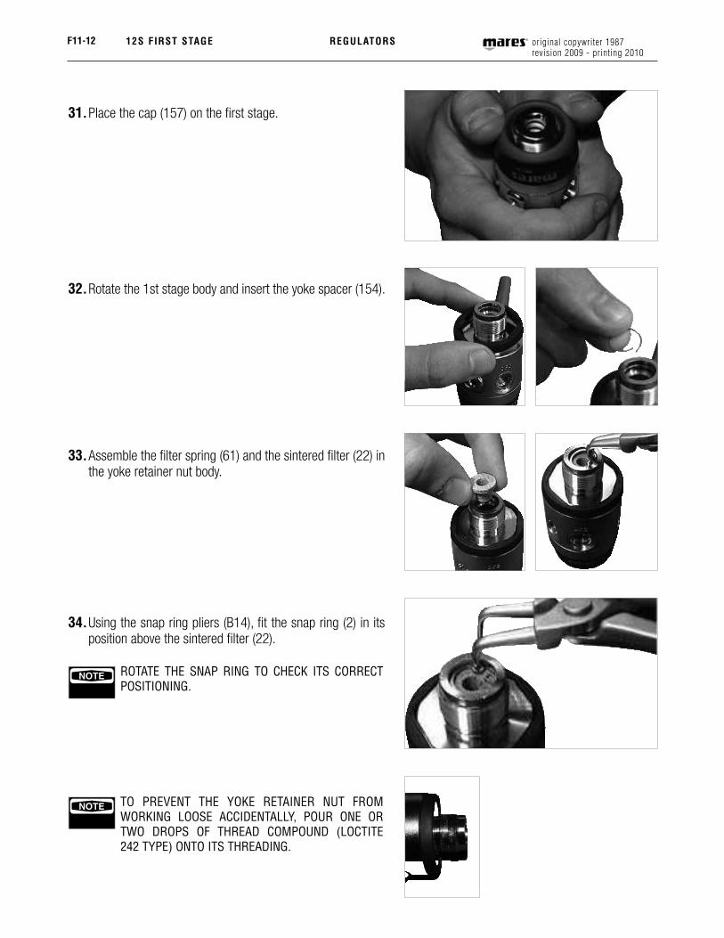
31. Place the cap (157) on the first stage.
32. Rotate the 1st stage body and insert the yoke spacer (154).
33. Assemble the filter spring (61) and the sintered filter (22) in the yoke retainer nut body.
34. Using the snap ring pliers (B14), fit the snap ring (2) in its position above the sintered filter (22).
NOTE ROTATE THE SNAP RING TO CHECK ITS CORRECT POSITIONING.
NOTE TO PREVENT THE YOKE RETAINER NUT FROM WORKING LOOSE ACCIDENTALLY, POUR ONE OR TWO DROPS OF THREAD COMPOUND (LOCTITE 242 TYPE) ONTO ITS THREADING.

F11-1312S FIRST STAGEoriginal copywriter 1987revision 2009 - printing 2010
REGULATORS
35. Position the yoke (3) with the knob (25) on the first stage body.
36. Using the wrench (B1), fully tighten the complete yoke retainer nut (7).
NOTE IF USING A TORQUE WRENCH, USE TIGHTENING TORQUE OF APPROXIMATELY 18-20 N/m.
DIN VERSION
37. Install the O-Ring (171) on the DIN coupling (48).
NOTE TO PREVENT THE NUT YOKE RETAINER FROM WORKING LOOSE ACCIDENTALLY, PUT ONE OR TWO DROPS OF THREAD COMPOUND (LOCTITE 222 TYPE) AT THE BEGINNING THREADS.
38. Place the DIN ring nut (49) on the DIN chamber nut (192) and then fully tighten the coupling (48).
NOTE IF USING A TORQUE WRENCH, USE TIGHTENING TORQUE OF APPROXIMATELY 18-20 N/m

F11-14 original copywriter 1987revision 2009 - printing 2010
12S FIRST STAGE REGULATORS
39. Insert the tapered filter (56) into the DIN connector.40. Position the O-Ring (188) on the OR seat (187).
41. Screw the O-Ring housing (187) to the DIN fitting (48) with a 4 mm Allen wrench and unscrew the disassembly tool (B5) from the first stage body.
NOTE IF USING A TORQUE WRENCH, USE TIGHTENING TORQUE OF APPROXIMATELY 1.5-2 N/m.
NOTE CONNECT THE FIRST STAGE TO A FULL TANK (AT LEAST 180 BAR) OR TEST BENCH, AND OPEN THE AIR VALVE SLOWLY TO EXPEL ANY FOREIGN MATTER FROM THE FIRST STAGE.
42. Position the O-Rings (19 - 52) on the caps (20 - 53).
43. Tighten the caps (20 - 53) to the first stage body (1) using a 4 mm Allen wrench and the flexible hoses in the corresponding ports on the first stage.
NOTE FOR CHECKS AND ADJUSTMENTS ON THE FIRST STAGE, CONSULT THE CORRESPONDING SECTION OF THE MAINTENANCE MANUAL : F 7-1 (2008)

F11-1512S FIRST STAGEoriginal copywriter 1987revision 2009 - printing 2010
REGULATORS
CWD DRY
a. Place the diaphragm (14) in the CWD Dry body (57), making it adhere perfectly to the edges.
b. Tighten the retaining nut (57) including the diaphragm (14) to the 1st stage body (1). Use a 30 mm wrench (B40) to fully tighten the CWD body (57) to the 1st stage body.
NOTE IF USING A TORQUE WRENCH, USE TIGHTENING TORQUE OF APPROXIMATELY 32-35 N/m.
c. Place the metal spring base plate (194) in the middle of the diaphragm (14).
d. Position the spring (16) over the metal spring base plate (194).
e. Screw the adjusting nut (18) 3 – 4 turns on the retaining nut (57) using a 10 mm Allen wrench (B13).
! WARNING!DO NOT OVER-TIGHTEN THE ADJUSTING NUT; THIS WILL CAUSE AN INCREASE IN INTERMEDIATE PRESSURE, INTERFERING WITH SUBSEQUENT ADJUSTMENTS
f. After calibrating the intermediate pressure on the first stage (9.0-9.4 bar), place the shock ring (190) on the CWD body (57).
! WARNING!ALL THE OPERATIONS DESCRIBED BELOW MUST BE PERFORMED WITH THE REGULATOR PRESSURIZED!

F11-16 original copywriter 1987revision 2009 - printing 2010
12S FIRST STAGE REGULATORS
g. Position the CWD Dry piston inside the CWD Dry body (57).
h. Arrange the CWD Dry diaphragm (193) over the piston (189) and hold it in place with your finger.
i. Tighten the cap (191) to the CWD Dry body (57) and tighten the 10 mm Allen wrench (B13), making sure that the diaphragm (193) has stayed in place.
NOTE IF USING A TORQUE WRENCH, USE TIGHTENING TORQUE OF APPROXIMATELY 32-35 N/m.
NOTE RUN SOME SUPPLY CYCLES FOR A FEW MINUTES. CHECK THE INTERMEDIATE PRESSURE. IT MUST BE BETWEEN 9.2 AND 9.6 BAR. ADJUST AGAIN IF NECESSARY.
F11-18 original copywriter 1987revisione 2009 - stampa 2010
12S FIRST STAGE
Drawing# E112
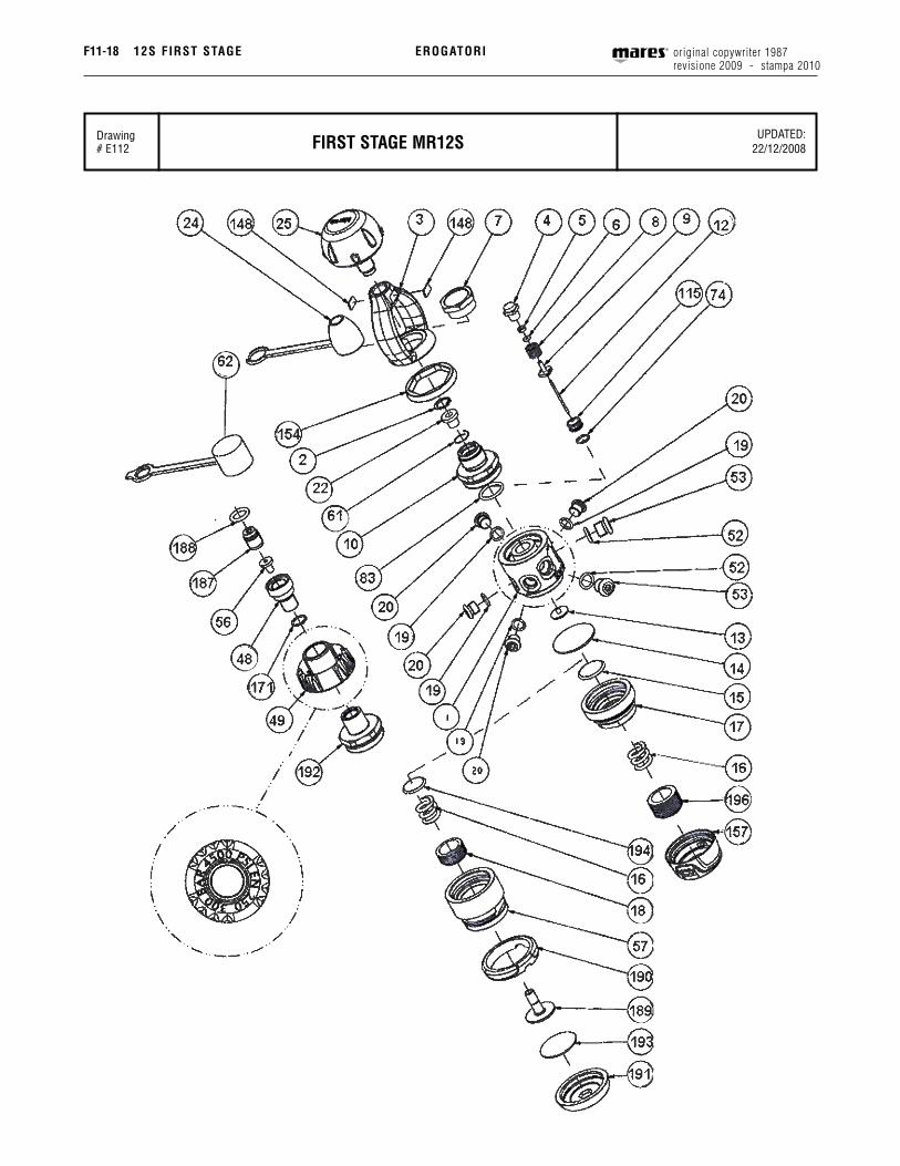
UPDATED:22/12/2008FIRST STAGE MR12S
EROGATORI

F11-1912S FIRST STAGEoriginal copywriter 1987revision 2009 - printing 2010
Table# 35
UPDATED : 22/12/2008FIRST STAGE MR12S
REGULATORS
REF CODE DESCRIPTION REF CODE DESCRIPTION1 46200944 First stage body 12S 74 46110107 OR 20312 46185015 Seeger d. Int. 13 74 46110403 OR 2031 viton 011-97073 46185211 Yoke 2000 83 46110225 OR 20684 D Hp chamber 83 46110420 OR 2068 viton5 46185038 Backup ring 1st stg regulator 115 46186216 Poppet seat mr6 46110101 OR 2012 148 46184315 Label yoke "en 250"6 46110401 OR 2012 viton 006-9707 149 46184316 Oval label7 46185212 Nut yoke retainer 1st stage mr12 154 46200930 Plastic ring int 12s8 46185011 Spring, 1st stage valve, mr12 157 46200929 Hock cap, 1st stage 12S9 46200652 Poppet 1° stg tri-material 171 46110110 OR 203710 46200940 Connector body int 171 46200298 OR 2037 viton12 46186214 Pin poppet MR12 32,5 mm 187 46200946 O-Ring seat din 12S13 46185032 Button, 1st st. Poppet 188 46110247 OR 304314 46185022 Diaphragm, 1st stage regulators 188 46200620 OR 3043 viton15 46185034 Plate spring base 189 46200925 Cwd dry 12S piston16 46185023 Spring diaphragm 1st stage reg. 190 46200923 Plastic ring cwd dry 12S17 46200938 Retaining nut 12S 191 46200922 Hock cup cwd dry 12S18 46185028 Regulating nut, cwd 192 46200942 Conn. Body hp din 12S19 46110106 OR 106 193 46200926 Diaphragm, cwd dry 12S 19 46110402 OR 106 viton 610-9707 194 46200950 Plate spring base cwd dry20 46185204 Lp plug 3/8", 1st stage, regs. 196 46184511 Regulating nut, 1st stage22 46186202 1st stage filter, regulators ASSEMBLIES24 46185010 Dust cap A 416209 1st stage assembly 12S (int-din)25 46184079 Yoke knob D 46185210 Hp housing assy, 1st stage ( 4-5-6 )48 46200934 Connecting plug, din 300 bar 12S D 46186259 Hp housing assy, 1st std (viton o-rings)49 46200932 Din 300 bar threaded locking ring F 416807 Din connector 300 12S (48-49-56-62-171-187-188-192)52 46110108 OR 108 I 416856 Kit cwd dry 12S52 46110404 OR 108 viton 611-9707 ### 46200963 Service kit 1st stg 12S int53 46185205 Hp plug 7/16", 1st stage ### 46200965 Service kit 1st stg 12S int (viton o-rings)56 46200948 Filter, din connector, 12S (2-5-6-19-22-52-74-83)57 I Cwd dry 12S body °°° 46200964 Service kit 1st stg 12S din61 46185013 Spring, filter 1st. Stage °°° 46200966 Service kit 1st stg 12S din (viton o-rings)62 46200562 Dust cap 300 bar din connector (5-6-19-52-56-74-83-171-188)