
Jenny Hughes Loek Nieuwenhuis A Project Manager’s Guide to

Hughes 9250 User GuideP/N 3500153
Version 2.0

Copyright 2008 Hughes Network Systems, LLC.
All rights reserved. This publication and its contents are proprietary to Hughes Network Systems, LLC. No partof this publication may be reproduced in any form or by any means without the written permission ofHughes Network Systems, LLC., 11717 Exploration Lane, Germantown, Maryland 20876.
Hughes Network Systems, LLC., has made every effort to ensure the correctness and completeness of thematerial in this document. Hughes Network Systems, LLC., shall not be liable for errors contained herein. Theinformation in this document is subject to change without notice. Hughes Network Systems, LLC. makes nowarranty of any kind with regard to this material, including, but not limited to, the implied warranties ofmerchantability and fitness for a particular purpose.
TrademarksAll trademarks, marks, names, or product names referenced in this publication are the property of theirrespective owners, and Hughes Network Systems, LLC. neither endorses nor otherwise sponsors any suchproducts or services referred to herein.
HUGHES and Hughes Network Systems are trademarks of Hughes Network Systems, LLC.
INMARSAT is a trademark of the International Mobile Satellite Organization. The Inmarsat LOGO and thetrademark BGAN are trademarks of Inmarsat (IP) Company Limited. All trademarks are licensed toInmarsat Limited.

Hughes 9250 BGAN Terminal User Guide i
SAFETY INFORMATIONFor your safety and protection, read this entire user manual before you attempt to use theBroadband Global Area Network (BGAN) Land Mobile Satellite Terminal. In particular, read thissafety section carefully. Keep this safety information where you can refer to it if necessary.
WARNING SYMBOLS USED IN THIS MANUAL
WARNING
Potential radio Frequency (RF) hazard. Where you see this alert symbol andWARNING heading, strictly follow the warning instructions to avoid injury toeyes or other personal injury.
WARNING
Where you see this alert symbol and WARNING heading, strictly follow thewarning instructions to avoid personal injury.
DANGER
Electric shock hazard: Where you see this alert symbol and DANGER heading,strictly follow the warning instructions to avoid electric shock injury or death.
WARNINGS FOR SATELLITE TERMINAL
DO NOT STAND IN FRONT OF THE ANTENNA
This device emits radio frequency energy. To avoid injury, do not place head orother body parts in front of the satellite antenna when system is operational.Maintain a distance of two meters or more from the front of the SatelliteTerminal antenna.
PROPERLY GROUND THE EXTERNAL ANTENNA
Failure to properly ground the optional external antenna may result in severepersonal injury or death. Do not attempt to ground the optional externalantenna unless you have the skills to do so in accordance with local electricalcodes.
DO NOT OPERATE DURING ELECTRICAL STORMS
Operation of the Satellite Terminal during electrical storms may result in severepersonal injury or death. Disconnect the Terminal from the computer and storethe unit indoors if lightning is anticipated in the area of operation.

ii Hughes 9250 BGAN Terminal User Guide
GENERAL
Handle your Satellite Terminal with care. The enclosure is weather resistant perIEC 60529 IP55; however, do not submerge the unit or expose it to severe rainstorms. Avoid exposing your Satellite Terminal to extreme hot or coldtemperatures outside the range -25ºC to +60ºC.
Avoid placing the Terminal close to cigarettes, open flames or any source ofheat.
Changes or modifications to the Terminal not expressly approved by HughesNetwork Systems could void your authority to operate this equipment.
Only use a soft damp cloth to clean the Terminal.
To avoid impaired Terminal performance, please ensure the unit’s antenna isnot damaged or covered with foreign material like paint or labeling.
When inserting the USIM/SIM, do not bend it or damage the contacts in anyway. When connecting the interface cables, do not use excessive force.
IN THE VICINITY OF BLASTING WORK AND IN EXPLOSIVE ENVIRONMENTS
Never use the Satellite Terminal where blasting work is in progress. Observe allrestrictions and follow any regulations or rules. Areas with a potentiallyexplosive environment are often, but not always, clearly marked. Do not usethe Terminal while at a petrol filling station. Do not use near fuel or chemicals.
QUALIFIED SERVICE
Do not attempt to disassemble your Satellite Terminal. The unit does notcontain consumer-serviceable components. Only qualified service personnelmay install or repair equipment.
BATTERIES AND ACCESSORIES
Use approved batteries (Hughes P/N 3500065-0001) and accessories only. Useof non-approved accessories may result in loss of performance, damage tothe Satellite Terminal, fire, electric shock or injury.
DC/DC power adapter (Hughes P/N 9501495-0001) is for indoor use only. It hasan indoor operating temperature range of 0ºC to +40ºC and provides 120W atoutput voltage of 19 VDC.
The storage capacity of the battery decreases when operated.
The terminal will only charge the battery when the temperature is within therange of 0 to 45°C.
CONNECTING DEVICES
Never connect incompatible devices to the Satellite Terminal. Whenconnecting the Satellite Terminal to any other device, read the device’s UserManual for detailed safety instructions.
Hughes 9250 BGAN Terminal User Guide iii
PACEMAKERS
The various brands and models of cardiac pacemakers available exhibit awide range of immunity levels to radio signals. Therefore, people who wear acardiac pacemaker and who want to use a Satellite Terminal should seek theadvice of their cardiologist. If, as a pacemaker user, you are still concernedabout interaction with the Satellite Terminal, we suggest you follow theseguidelines:
Maintain a distance of 30 cm between the Terminal and your pacemaker;
Maintain a distance of two meters from the front of the unit’s antenna;
Refer to your pacemaker product literature for information on your particular device.
If you have any reason to suspect that interference is taking place, turn offyour Satellite Terminal immediately!
HEARING AIDS
Most new models of hearing aids are immune to radio frequency interferencefrom Satellite Terminals that are more than 2 meters away. Many types of olderhearing aids may be susceptible to interference, making it very difficult to usethem near a Terminal. Should interference be experienced, maintainadditional separation between you and the Satellite Terminal.
iv Hughes 9250 BGAN Terminal User Guide
CONTENTS
SAFETY INFORMATION _____________________________________________ I
Warning Symbols Used in this Manual...................................................... i
Warnings for Satellite Terminal................................................................... i
CONTENTS ____________________________________________________ IV
INTRODUCTION _________________________________________________ 1
About This Product......................................................................................1
About This User Guide................................................................................2
Package Contents .....................................................................................3
Minimum System Requirements ...............................................................3
GETTING STARTED _______________________________________________ 4Introduction to Getting Started ...............................................................4
Setting Up Your Terminal............................................................................4
USING THE HUGHES 9250_________________________________________ 5
Auto Start configuration............................................................................5
Features of the Hughes 9250 .................................................................... 6
Power Up and Connection to the Internet............................................6
Coverage Map ...........................................................................................7
USING THE HUGHES UT WEB MMI __________________________________ 8Accessing the UT Web MMI......................................................................8
Properties Page...........................................................................................9
Setup Page ................................................................................................11
Statistics.......................................................................................................13
PDP Contexts .............................................................................................14
WLAN...........................................................................................................18
Connecting by WLAN.......................................................................18WEP Security...............................................................................................19
ACA.............................................................................................................21
ISDN .............................................................................................................25
Antenna......................................................................................................27
TROUBLE SHOOTING ____________________________________________ 29
TECHNOLOGY OVERVIEW ________________________________________ 31
GPS ..............................................................................................................31
Obtaining a GPS Fix...........................................................................31GPS and BGAN Registration ............................................................31
ISDN .............................................................................................................32
Dialing and Numbering ....................................................................32

Hughes 9250 BGAN Terminal User Guide v
PDP Context...............................................................................................32
WLAN...........................................................................................................33
Performance.......................................................................................33SSID........................................................................................................33
TECHNICAL SPECIFICATIONS ______________________________________ 34
DECLARATION OF CONFORMITY ___________________________________ 35
FCC Compliance......................................................................................35
EU WEEE (Waste Electrical and Electronic Equipment) Directives ..36
GLOSSARY ___________________________________________________ 37


Hughes 9250 BGAN Terminal User Guide 1
INTRODUCTION
ABOUT THIS PRODUCT
The Hughes Network Systems (HNS) 9250 Broadband Satellite Terminal and WLAN Access Point isyour gateway to global communication. The 9250 allows you to simultaneously send andreceive IP packet and circuit-switched data via Ethernet, Integrated Services Digital Network(ISDN), and WLAN interfaces over the Inmarsat BGAN satellite network.
The unit offers you the following features and benefits:
Fully autonomous tracking antenna acquires and tracks the BGAN satellite signal whileon the move
Easy antenna installation (magnetic mount) on vehicle roof
Includes antenna control unit and all cables and power supplies for vehicular installation
Up to 464 Kbps data (transmit and receive) and 256 Kbps streaming IP data rate1.However, below 45 degree look angle to the satellite the max streaming rate is 128kbps.
Speech (4Kbps)
ISDN voice (3.1KHz audio) (above 15 degree look angle to the satellite)
ISDN data (64Kbps) (above 15 degree look angle to the satellite)
WLAN access point
Multi-user capability for sharing a single unit
Selectable Quality-of-Service (QoS)
Full IP compatibility for Email, file transfer (FTP), browsing, VPN, etc.
Cost-effective “always-on” access – charges only for data sent and received
UMTS IP-based services
WLAN, FCC, CE, and GMPCS certified
Subscriber Identification Module (SIM) card security
GPS and WLAN status LEDs
The unit is easy to install and connects in minutes. It is built for use in vehicular environments.
The Satellite Terminal carries a warranty for 12 months from the date of sale. Contact yourService Provider if you have questions about the warranty, or need to return the terminal forrepair.
In this document, the following names and abbreviations are used to identify the SatelliteTerminal and your computer.
Term Definition
Terminal Satellite TerminalTE Terminal Equipment (your computer)
UT User Terminal/satellite terminal
1 . Best efforts performance under moving conditions depending on obstruction of satellite signal. Performance is limitedby the BGAN system design: Signal outages of more than 60 seconds will cause circuit switched calls to be dropped andpacket switched sessions being interrupted. May require user intervention to reactivate connections for longer outagedurations

2 Hughes 9250 BGAN Terminal User Guide
ABOUT THIS USER GUIDE
This user guide contains the most up-to-date information available on this product, on the date itwas generated. It is focused on the specific information needed to operate the Hughes 9250Land Mobile User Terminal and to document the differences to the Hughes 9201 BGAN Class 1Satellite Terminal.
Please refer to the Hughes 9201 User Guide for general information on how to access the BGANnetwork and how to use the Inmarsat LaunchPad Software.
Hughes 9250 BGAN Terminal User Guide 3
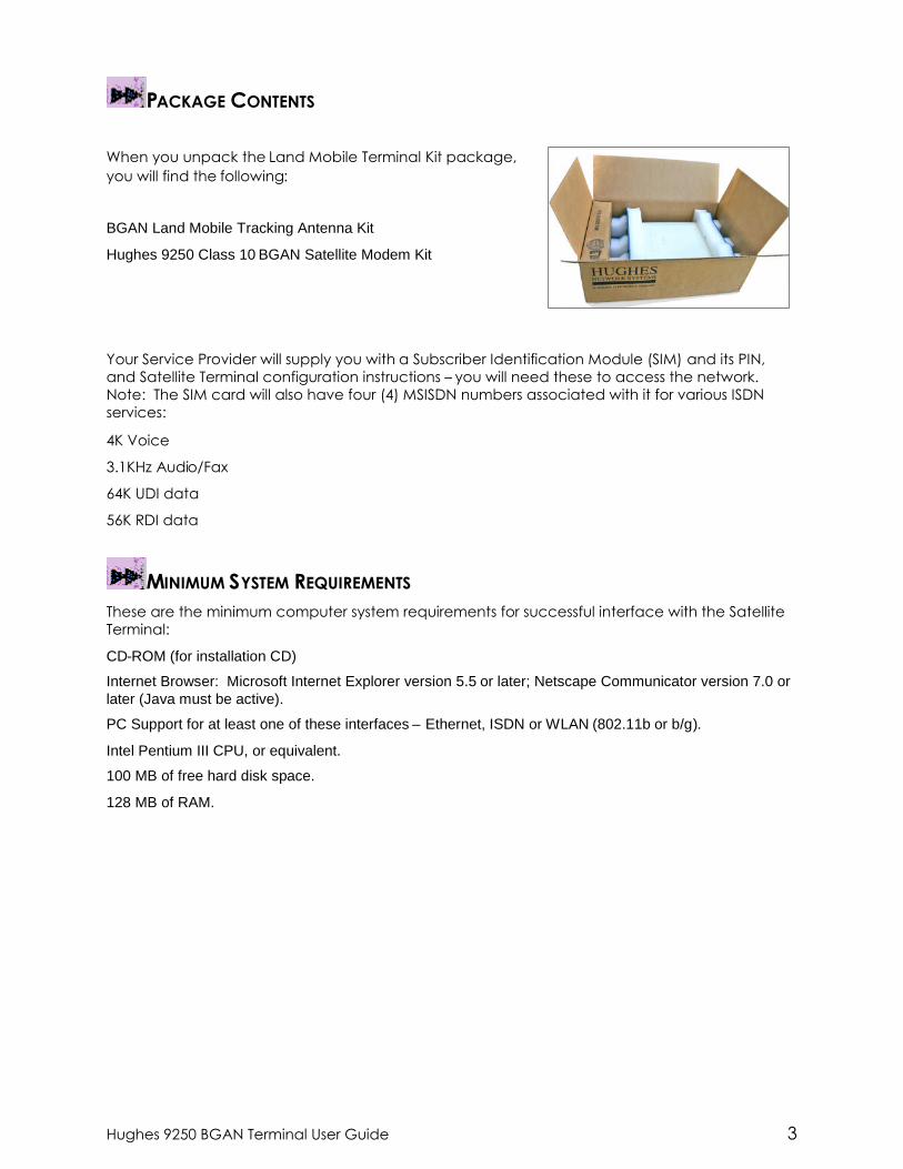
PACKAGE CONTENTS
When you unpack the Land Mobile Terminal Kit package,you will find the following:
BGAN Land Mobile Tracking Antenna Kit
Hughes 9250 Class 10 BGAN Satellite Modem Kit
Your Service Provider will supply you with a Subscriber Identification Module (SIM) and its PIN,and Satellite Terminal configuration instructions – you will need these to access the network.Note: The SIM card will also have four (4) MSISDN numbers associated with it for various ISDNservices:
4K Voice
3.1KHz Audio/Fax
64K UDI data
56K RDI data
MINIMUM SYSTEM REQUIREMENTS
These are the minimum computer system requirements for successful interface with the SatelliteTerminal:
CD-ROM (for installation CD)
Internet Browser: Microsoft Internet Explorer version 5.5 or later; Netscape Communicator version 7.0 orlater (Java must be active).
PC Support for at least one of these interfaces – Ethernet, ISDN or WLAN (802.11b or b/g).
Intel Pentium III CPU, or equivalent.
100 MB of free hard disk space.
128 MB of RAM.

4 Hughes 9250 BGAN Terminal User Guide
GETTING STARTED
INTRODUCTION TO GETTING STARTED
This guide is the simplest and quickest way to connect to the BGAN network. If you are a firsttime user, you will be guided through the procedure for powering up your terminal, obtaining aGPS fix, connecting your computer to the terminal and registering with the BGAN network. Youare then ready to start using voice and broadband services.
SETTING UP YOUR TERMINAL
Set up the Hughes 9250 terminal according to the Quick Install Guide P/N 3500145-0001 suppliedwith the terminal.

Hughes 9250 BGAN Terminal User Guide 5
USING THE HUGHES 9250
AUTO START CONFIGURATION
Since the Hughes 9250 is equipped with a tracking antenna, the default configurations for theHughes 9250 Land Mobile Terminal are as follows:
The Hughes 9250 is configured to bypass antenna pointing as default and will automatically register withthe network: The terminal will automatically attempt to register with the network once the tracking antennahas acquired the satellite signal and obtained a GPS fix.
The Hughes 9250 is configured for Auto Power “On” mode: The terminal automatically powers up whenthe DC power adapter is plugged in.

6 Hughes 9250 BGAN Terminal User Guide
Note
These default configurations are accessible through LaunchPad or the web MMIand It is recommended to keep these settings for convenient operation of theHughes 9250 Land Mobile Terminal.
FEATURES OF THE HUGHES 9250The User should be aware of the following differences between the Hughes 9250 Land MobileTerminal and the Hughes 9201 Satellite Terminal:
The Hughes 9250 is configured for automatic registration with the network as discussed above.
The Hughes 9250 will automatically power off after 30 seconds when the DC power adapter isremoved, even though a battery is inserted. This feature will prevent the user from operating thepower button to operate the terminal.
The Hughes 9250 operates as a BGAN Class 10 terminal. It can only establish a 256Kbpsstreaming class connection at elevation angles above 45°.
POWER UP AND CONNECTION TO THE INTERNET
After power is applied, the Hughes-9250 Terminal and Hughes Tracking Antenna will begin theirstart-up sequence. The tracking antenna will begin its search of the BGAN satellite and theantenna motors may be heard during this time. Note that the tracking antenna must have lineof sight of the BGAN satellite. Once the antenna has locked onto the BGAN satellite, it willcontinue to make minor adjustments to acquire optimum signal strength. The antenna may beheard ‘twitching’ during this time. Eventually the antenna will sit at an optimum position whilethe vehicle is stationary.
Refer to the Hughes 9201 Terminal User Guide for instructions on
How to connect a Personal Computer or Mac to the terminal.
How to establish a data connection to the Internet
How to use the LaunchPad user interface
How to connect and use ISDN terminals
Once the vehicle starts moving, the Hughes Tracking Antenna will automatically track thesatellite signal and keep the antenna pointed towards the satellite. During short outages (e.g.while driving under a bridge, etc.) the antenna will remain in the same position and will pick upthe satellite signal immediately. For longer outages the antenna may need to repeat the searchpattern to reacquire the satellite signal.
Note
Circuit switched and packet switched connections will recover from signal outagesof less than 60 seconds. User intervention may be required to reactivateconnections for outage longer than 60 seconds.

Hughes 9250 BGAN Terminal User Guide 7
COVERAGE MAP
The Hughes 9250 will perform best in areas where the elevation angle is 20 degrees or higher.Lower elevation angles increase the probability of signal outages caused by trees, buildings andhilly terrain and may severely impact the usability on the move.

8 Hughes 9250 BGAN Terminal User Guide
USING THE HUGHES UT WEB MMI
ACCESSING THE UT WEB MMI
The Hughes UT now includes its own internal Web MMI. To access the UT Web MMI, open yourfavorite Web Browser and type in the internal IP address of the UT e.g. http://192.168.128.100.The web MMI opens up to the “Properties” page as shown below:

Hughes 9250 BGAN Terminal User Guide 9
PROPERTIES PAGE
The Properties page shows the current status of the UT. A description of each item on the pagefollows:
In the Top left-hand corner of the screen you will notice that there are three status items: SatelliteSignal Strength, Beam ID, and battery status. These items are updated automatically whenstatus of that item changes.
Network Status: This shows the current status of the network and there are two messages thatappear in this field:
1. Registration Status: This filed indicates whether you are Registered with the Network.Click on the “Register with Network” button. Note: For the 9250, bypass antenna pointingis turned on as default so it will automatically register with the Network each time.

10 Hughes 9250 BGAN Terminal User Guide
2. PS Attach Status: This indicates whether you are PS (Packet Switch) attached with theNetwork. You will still need to setup a PDP context in order to send PS data.
3. CS Attached: This indicates whether you are CS (Circuit Switch) attached with theNetwork. Once you are CS Attached and Registered with the network, you are able tomake CS calls.
4. GPS Position: This field displays the current GPS position status. If you have received aGPS fix and the Network GPS policy has been received and it allows the GPS position tobe shown to the user, it will display the Latitude, Longitude, Fix Quality, and the Last timethe GPS position was updated. Time displayed is GMT time.
5. Emergency Call Numbers: This field displays the Emergency call numbers that can beused with the UT.
6. Software Version: This displays the current version of software that is running on the UT.
7. Satellite Modem IMEI: This displays the IMEI number of the UT.
8. Satellite Modem IMSI: This displays the IMSI number of the USIM card in the UT. If is theIMSI is not displayed, it indicates that there is a problem reading the SIM card, e.g.because there is no SIM, it is installed incorrectly or PIN must be entered.
9. USIM PIN Status: This field indicates whether the USIM is ready or the PIN has to beentered. If the PIN needs to be entered, go to the SETUP page.
10. USIM APN Name: This displays the default APN that has been provisioned on the USIMcard. Note that some USIM cards may have multiple APN’s provisioned on them.
11. MS-ISDN 1 thru 4: Every USIM card has four (4) separate MS-ISDN numbers if the USIM hasbeen provisioned for these services. MS_ISDN 1 is for 4K Speech, MS-ISDN 2 is for 3.1KHzAudio (fax, etc.), MS-ISDN 3 is for UDI data and MS-ISDN 4 is for RDI data.
12. Extract System Log: Clicking this button allows the User to automatically extract a UTsystem log and save the file to a location on the TE for debugging purposes. This file canbe e-mailed to Hughes directly for fault analysis if the User experiences any problems.
13. Restore factory Defaults: Clicking this button will restore the UT back to factory defaultsand delete any of the User parameters that have been set-up in the UT. Hughes highlyrecommends that the User exhaust all possible debug procedures before using thisfeature.

Hughes 9250 BGAN Terminal User Guide 11
SETUP PAGE
The Setup page allows the User to configure various parameters of the UT. A description of eachitem on the page follows:
1. Terminal Local IP Address: This allows the User to change the local IP address of theterminal from the default 192.168.128.100 IP address. Only the last two octets areavailable to change. Once the local IP address is changed on this page and applied,the IP address ranges for the DHCP server, the PDP Context page and ACA page will alsobe changed automatically. Note: Updates to this field will not take affect until the UT isrebooted.
2. DHCP Address Range: This allows the User to set the range of DHCP addresses that aregiven out by the UT to any connected TE.
3. Idle-mode DHCP Lease Time: Idle-mode DHCP Lease Time refers to the DHCP lease timewhen the UT is not connected to the network. This parameter allows the User to changethe default time (60 seconds) that the DHCP lease to the TE is good for. This parameter

12 Hughes 9250 BGAN Terminal User Guide
was introduced because of a problem with some models of Cisco routers that will notaccept a short DHCP lease time. Note: The longer the Idle-mode DHCP lease time, thelonger it will take the Network/UT to update the TE with the correct DNS servers for webbrowsing after establishing a PDP context.
4. Connected-mode DHCP Lease Time: The Connected-mode DHCP Lease Time refers tothe DHCP lease time when the UT is connected to the network. Most Users will have noneed to change this parameter.
5. PIN and PUK: The PIN and PUK fields indicate whether the PIN or PUK needs to be enteredto unlock the terminal. When greyed out they indicate the PIN is not required or isalready satisfied.
6. Bypass Antenna Pointing: This parameter allows the User to bypass antenna pointing andhave the UT go straight into Registering with the Network. This is turned “on” as default forthe 9250.
7. Auto Power On: This parameter is used when the User wants the UT to power upautomatically if AC/DC power is applied to the UT.
8. 24/7 PDP Keep Alive: This is setting is for keeping a PDP context alive indefinitely. Note:This parameter should not be checked unless you have a critical need to keep the PDPcontext alive for critical information. This is not a good use of satellite resources.
9. Satellite Selection: This parameter is used within a satellite overlap region and allows theuser to override the default satellite (selected by the 9250 based upon elevationangle/GPS location) and select a different satellite. Note: This change does not takeaffect until the UT is reset. When set to AUTO the UT will select the satellite based on theunit’s GPS position. When set to a specific satellite it will attempt to use that satellite only.Be careful to select the correct satellite for your position and note the time periods whenthe specific satellites are valid.
10. Net mode: Most users will use NAT mode for their application. Bridge mode requires theTE to be intelligent enough to handle two IP addresses and to be able to route traffic toeither address. One address is the UT’s private IP address and the other is the public IPaddress assigned by the network when a PDP context is activated.
11. Streaming Activity Timer: This allows the user to turn On a timer for inactivity for aStreaming QoS that has been setup. The timer is in seconds and will tear down astreaming context after X seconds of inactivity.
12. Emergency Call Numbers: Allows the User to update the emergency call number that isapplicable in that part of the world where the terminal is being used.
13. Apply, Cancel, and Restart Terminal buttons: These buttons are self explanatory.

Hughes 9250 BGAN Terminal User Guide 13
STATISTICS
This web page provides an estimate of the amount of Packet Switched data sent and received,along with time spent on a CS call. The data is broken up into three types:
Session: The PS session statistics track the cumulative PS data sent and received on backgroundPDP contexts since the unit was powered on. CS sessions statistics track the time of the last call.
Trip: The trip counter is similar to the trip counter on your vehicle. It can be zeroed out atanytime by the user and it will track the statistics until the User resets it.
Lifetime: The Lifetime counter is similar to the odometer on your vehicle. It shows the statistics ofthe terminal since the software version that added this feature was loaded onto the UT. The Usercannot reset these counters.
Note: If the UT power is abruptly disconnected for some reason, the UT will not be able tosave the statistics to flash and hence the statistics for the session maybe inaccurate.

14 Hughes 9250 BGAN Terminal User Guide
PDP CONTEXTS
The PDP Context page allows the User to setup and configure PDP contexts for any TE that isconnected to the UT. To activate a PDP Context, go to the bottom of the page. You will seethe CID, Local IP Address, APN, Requested QoS, Username and Password fields.
1. CID: The CID of each context is automatic by default. If for some reason the Userwants to assign a particular context to a specific CID, use the drop down arrow andselect the wanted CID number. Most users will not need to change this field from theautomatic default setting.
2. Local IP Address: This is the local IP address of the TE that you want to setup a PDPcontext for. Note that the first three octets of the IP address will reflect any changesmade in the setup screen to the UT local IP address. You can use the “ipconfig”command from a “cmd” window to find the IP address of a PC.
3. APN name: This field is configurable, but it will always show the default APN that hasbeen provisioned on the USIM. If you have a USIM that has been provisioned withmultiple APN’s, you can type in any of these secondary APN names as part of thePDP context setup.
4. Requested QoS: The drop down list shows all of the different QoS types: background,streaming 32K, streaming 64K, streaming 128K, and streaming 256K. Select theappropriate QoS required for the PDP context that you are setting up.
Hughes 9250 BGAN Terminal User Guide 15
5. Username (UN)/Password (PW): Some Service Providers require a Username andPassword to be used when setting up a PDP context. This is often required whenusing Static Global IP addresses assigned by the Service provider.
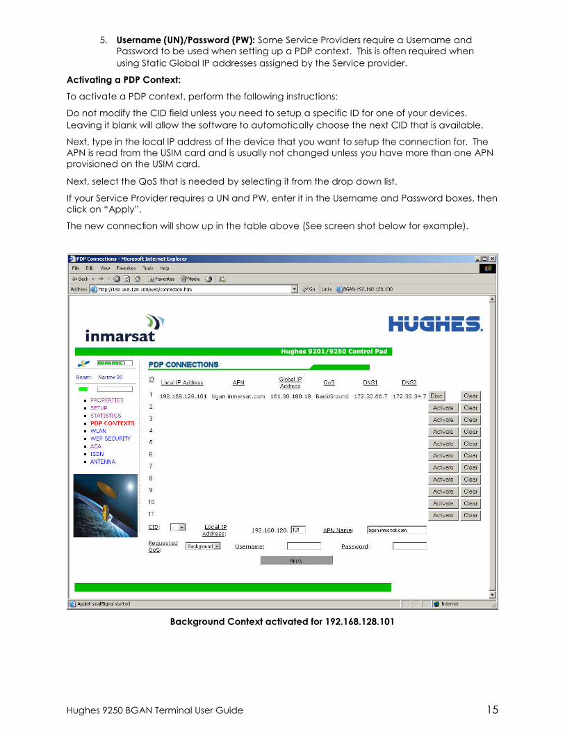
Activating a PDP Context:
To activate a PDP context, perform the following instructions:
Do not modify the CID field unless you need to setup a specific ID for one of your devices.Leaving it blank will allow the software to automatically choose the next CID that is available.
Next, type in the local IP address of the device that you want to setup the connection for. TheAPN is read from the USIM card and is usually not changed unless you have more than one APNprovisioned on the USIM card.
Next, select the QoS that is needed by selecting it from the drop down list.
If your Service Provider requires a UN and PW, enter it in the Username and Password boxes, thenclick on “Apply”.
The new connection will show up in the table above (See screen shot below for example).
Background Context activated for 192.168.128.101
16 Hughes 9250 BGAN Terminal User Guide
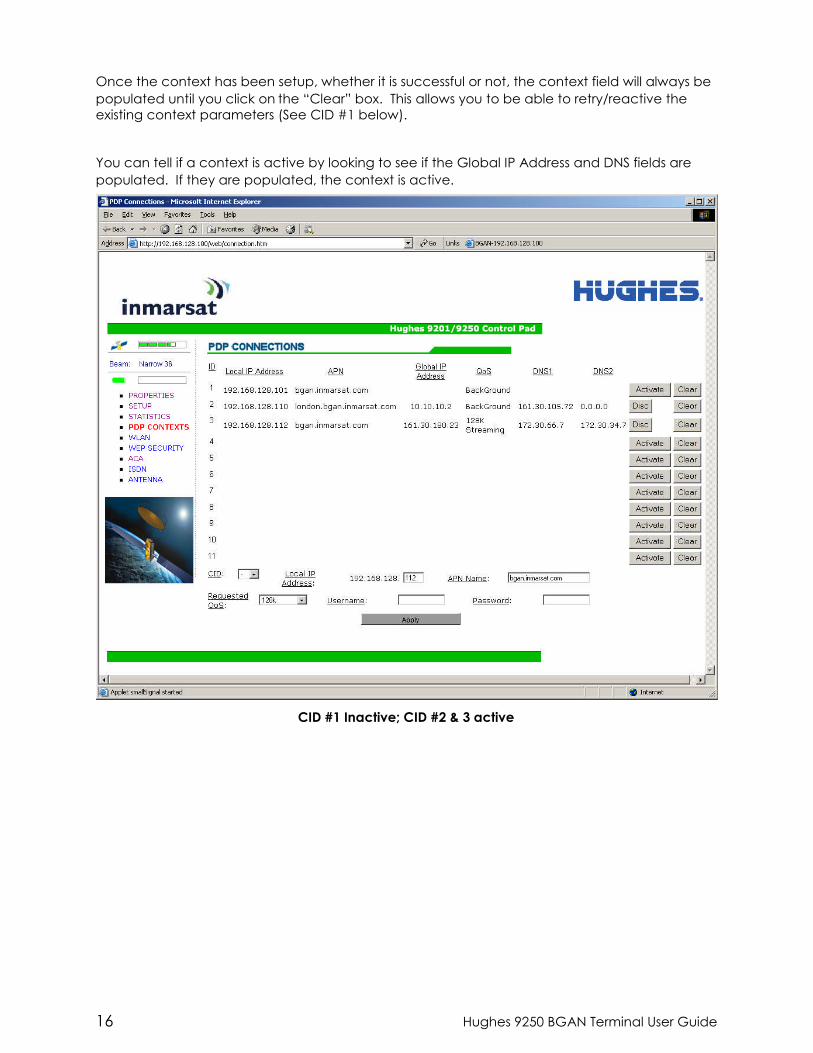
Once the context has been setup, whether it is successful or not, the context field will always bepopulated until you click on the “Clear” box. This allows you to be able to retry/reactive theexisting context parameters (See CID #1 below).
You can tell if a context is active by looking to see if the Global IP Address and DNS fields arepopulated. If they are populated, the context is active.
CID #1 Inactive; CID #2 & 3 active
Hughes 9250 BGAN Terminal User Guide 17
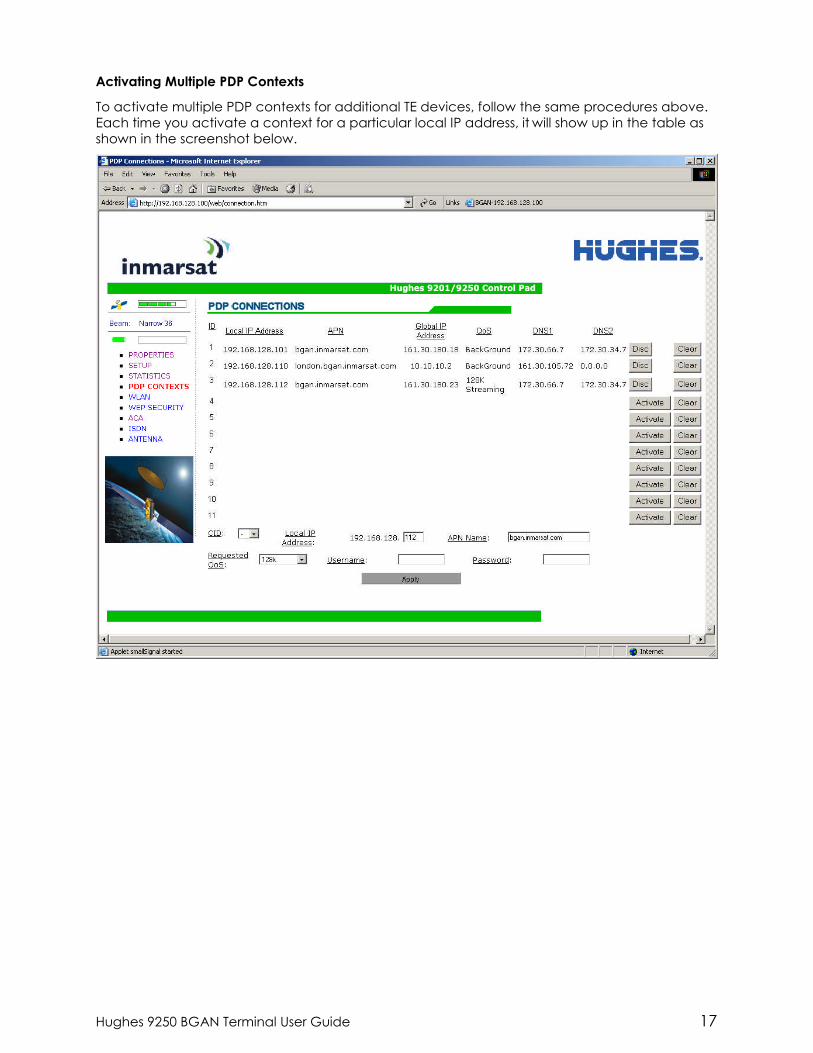
Activating Multiple PDP Contexts
To activate multiple PDP contexts for additional TE devices, follow the same procedures above.Each time you activate a context for a particular local IP address, it will show up in the table asshown in the screenshot below.
18 Hughes 9250 BGAN Terminal User Guide
WLAN
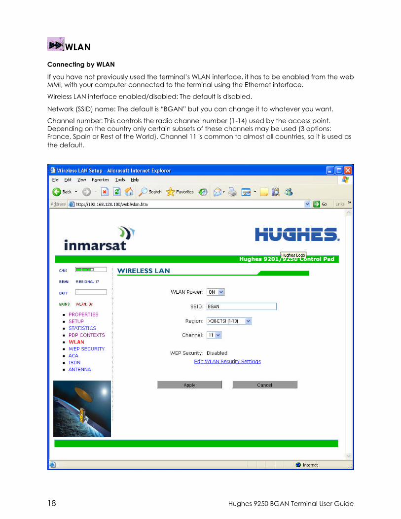
Connecting by WLAN
If you have not previously used the terminal’s WLAN interface, it has to be enabled from the webMMI, with your computer connected to the terminal using the Ethernet interface.
Wireless LAN interface enabled/disabled: The default is disabled.
Network (SSID) name: The default is “BGAN” but you can change it to whatever you want.
Channel number: This controls the radio channel number (1-14) used by the access point.Depending on the country only certain subsets of these channels may be used (3 options:France, Spain or Rest of the World). Channel 11 is common to almost all countries, so it is used asthe default.
Hughes 9250 BGAN Terminal User Guide 19
WEP SECURITY
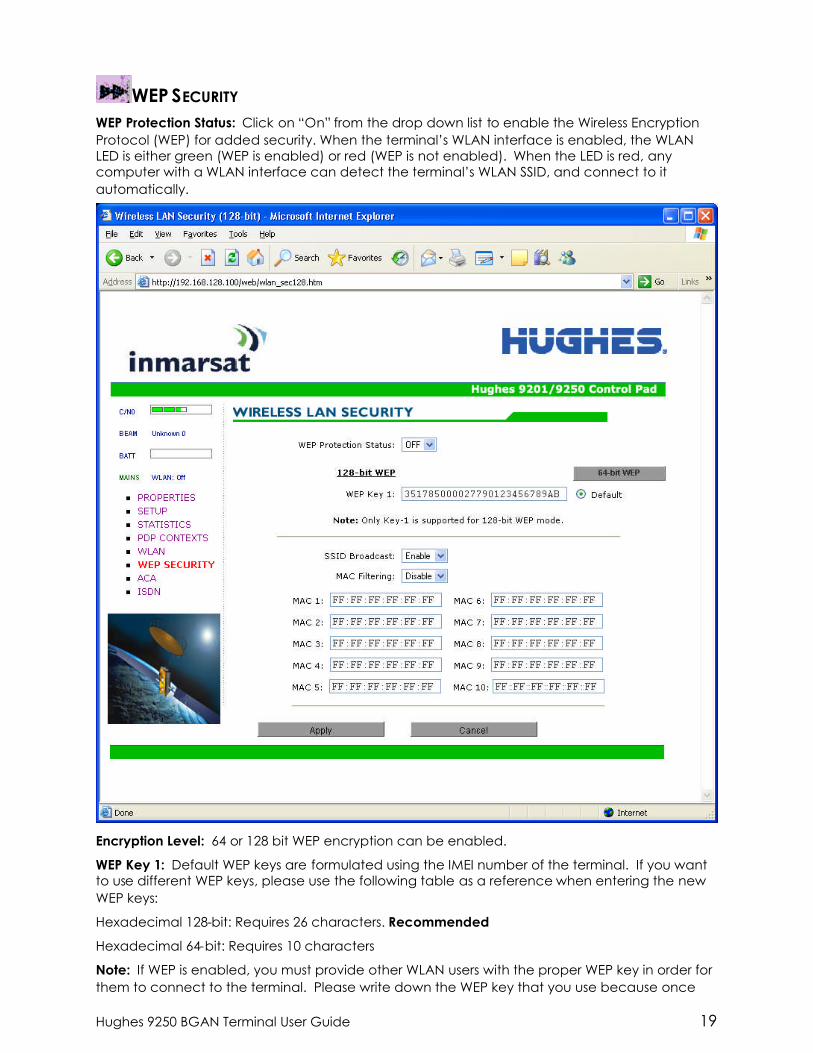
WEP Protection Status: Click on “On” from the drop down list to enable the Wireless EncryptionProtocol (WEP) for added security. When the terminal’s WLAN interface is enabled, the WLANLED is either green (WEP is enabled) or red (WEP is not enabled). When the LED is red, anycomputer with a WLAN interface can detect the terminal’s WLAN SSID, and connect to itautomatically.
Encryption Level: 64 or 128 bit WEP encryption can be enabled.
WEP Key 1: Default WEP keys are formulated using the IMEI number of the terminal. If you wantto use different WEP keys, please use the following table as a reference when entering the newWEP keys:
Hexadecimal 128-bit: Requires 26 characters. Recommended
Hexadecimal 64-bit: Requires 10 characters
Note: If WEP is enabled, you must provide other WLAN users with the proper WEP key in order forthem to connect to the terminal. Please write down the WEP key that you use because once

20 Hughes 9250 BGAN Terminal User Guide
entered, there is no way to view this key again. You will have to disable WEP, reboot theterminal and set it back up again if the WEP key is forgotten.
SSID Broadcast: For added security you can choose not to broadcast your SSID.
MAC Filtering: For added security, click on ENABLE from the drop down list and then you canchoose up to 10 selected MAC addresses that are allowed to connect to your WLAN. Note: Tofind out what the MAC address of a any TE is, go to a DoS prompt and type ipconfig /all.

Hughes 9250 BGAN Terminal User Guide 21
ACAThis web page allows you to use Automatic Context Activation (ACA) in two different ways;using static IP addresses in the TE device you can establish an automatic PDP context withany QoS that is offered by the network (upper half of the web page)or using DHCP from theUT, you can establish an automatic background PDP context for any TE that connects to theUT (lower part of the web page).
ACA settings for TEs with Static IP address:
Previously the static IP addresses used for ACA used specific blocks of IP addresses for thevarious QoS types. Now you can setup your own range of static IP addresses for setting upan automatic PDP context with any of the QoS’s offered by the network.
To turn on a particular range of addresses, select the “On” radio button and choose a rangeof addresses, low and high to use (e.g. 192.168.128.1 to 192.168.128.10).
Next select the desired QoS for that range of IP addresses (32K streaming). The APN listed isthe default APN read from the USIM card (bgan.inmarsat.com). If your USIM is provisionedfor more than one APN, then you can type a secondary APN in this field.
Next, if your Service Provider requires a UN and PW, enter it in the next two fields.

22 Hughes 9250 BGAN Terminal User Guide
If you want to setup additional ranges of addresses, please follow the same instructions asabove. Note: You cannot overlap the IP address ranges. If you do, an error will pop-uptelling you that you have an overlap region. Check all of the ranges for overlaps and tryagain.
When you are finished, click on “Apply” and you should see a message saying “OperationSuccessful” as shown below.
ACA settings for TEs using DHCP assigned IP address: This option allows you to set up the UTfor dynamic background ACA. This means that any device connected to the UT, willautomatically receive a background PDP context.
To activate this feature, select the “On” radio button under ACA settings for TEs using DHCPassigned IP address and click on “Apply”.

Hughes 9250 BGAN Terminal User Guide 23

24 Hughes 9250 BGAN Terminal User Guide
To see if the context has been setup properly, click on PDP Contexts page and this will showyou all contexts that have been setup (active or inactive). See screen shot below.

Hughes 9250 BGAN Terminal User Guide 25
ISDNYou can establish ISDN data communication by connecting your ISDN equipment directly to theBGAN Terminal’s ISDN port with the supplied ISDN cable (which is the same as the Ethernetcable). This web page allows you to activate 40V power sourcing on the ISDN interface, and setMSN numbering options.
1. ISDN Power Sourcing: To turn on the ISDN power sourcing click on the “On” radio button.The ISDN device should receive 40V power immediately via the ISDN cable. This field shouldbe on unless you never use ISDN or are using an ISDN device that has its own power source.
2. MSN Speech: By default, MSN 1 is entered into the MSN Speech number text box. To receiveincoming calls, you must program the same MSN into your ISDN handset connected to theISDN port.
3. MSN 3.1 KHz audio: By default, MSN 2 is entered into the MSN 3.1 KHz Audio number text box.To receive incoming calls, you must program the same MSN into your ISDN fax machineconnected to the ISDN port.
4. MSN UDI (Unrestricted Digital Information): By default, MSN 3 is entered into the MSN UDI textbox. UDI is a 64 Kbps service that is a European standard ISDN.

26 Hughes 9250 BGAN Terminal User Guide
5. MSN RDI (Restricted Digital Information): By default, MSN 3 is entered into the MSN RDI textbox. RDI is a 56 Kbps service that is normally found in the USA.
6. Trigger for Mobile-Originated call type (Bearer): This box controls the mechanism used bythe terminal to select the bearer type for mobile originated calls. By default, “Bearercapability” is set as the trigger in this text box. There is also an option under the drop downarrow to set the trigger to use the MSN rather than the bearer. Most ISDN devices correctlysignal the call type (speech, 3.1KHz audio, UDI, RDI) via the bearer capability. If there is aproblem, this field can be changed to use the MSN number instead.
Once all changes have been made, click on “Apply”. Any changes to this screen require a re-boot of the terminal to save the new configuration. Use the power button on the UT or the“Restart Terminal” button to gracefully power down and power back up the UT.
Note: You can use different MSNs for any of the ISDN call types above, but your ISDN equipmentmust be programmed with the same MSN to accept incoming calls, and you must use differentnumbers for speech, audio and UDI/RDI calls.
Hughes 9250 BGAN Terminal User Guide 27
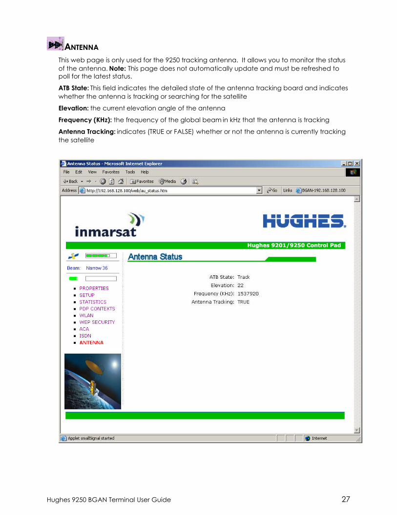
ANTENNA
This web page is only used for the 9250 tracking antenna. It allows you to monitor the statusof the antenna. Note: This page does not automatically update and must be refreshed topoll for the latest status.
ATB State: This field indicates the detailed state of the antenna tracking board and indicateswhether the antenna is tracking or searching for the satellite
Elevation: the current elevation angle of the antenna
Frequency (KHz): the frequency of the global beam in kHz that the antenna is tracking
Antenna Tracking: indicates (TRUE or FALSE) whether or not the antenna is currently trackingthe satellite

28 Hughes 9250 BGAN Terminal User Guide
Additional Information on the various antenna parameters (ATB states) are shown below:
# State name State Description0 INIT_ST Initial state1 IDLE_ST Wait on a frequency from the TU2 AZ_SEEK1_ST Determine min/max signal levels in a full sky scan3 AZ_SEEK2_ST Find azimuth direction4 AZ_SEEK_ELEVATION_ST Determine min/max signal levels on a single elevation5 TR_TUNE_EL_ST Track and tune elevation state6 TR_TUNE_PLL_ST Track and tune PLL state7 TRACK_ST Track state8 BLOCK_ST Blocked state9 FREEZE_ST Antenna has stopped all motors10 (0x0A) TEST_ST Test state
The field at the bottom of the page is true/false indicating whether the antenna is tracking, i.e. instates 5, 6 or 7.
The frequency is the frequency of the global beam. Possible values are the primary andsecondary frequencies of the 3 satellites.
Satellite ID Satellite Primary AlternateLongitude Freq kHz Freq kHz
I4-F1 IOR 64.0 E 1537485 1540825 Old position
I4-F1 APAC 143.5 E 1537485 1540825 New position
I4-F2 AOR 53.0 W 1537920 1541115 Old position
I4-F2 EMEA 25.0 E 1537920 1541115 New position
I4-F3 AMER 98.0W 1537070 1540730
Hughes 9250 BGAN Terminal User Guide 29
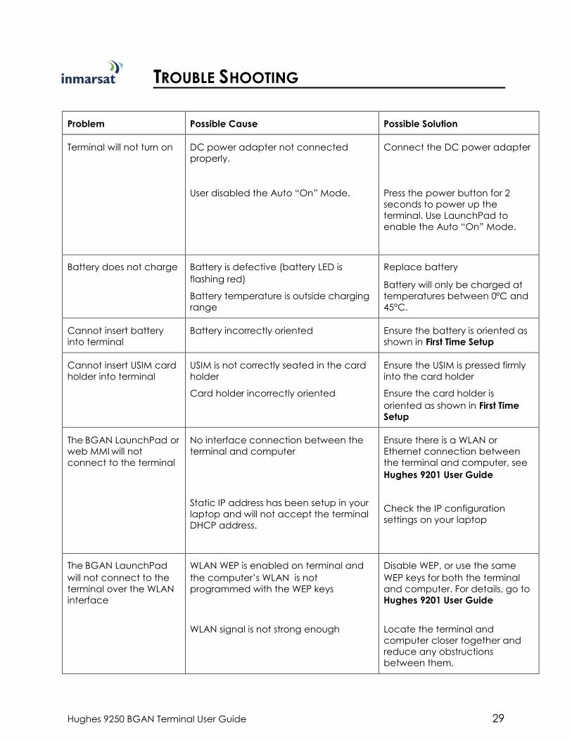
TROUBLE SHOOTING
Problem Possible Cause Possible Solution
Terminal will not turn on DC power adapter not connectedproperly.
User disabled the Auto “On” Mode.
Connect the DC power adapter
Press the power button for 2seconds to power up theterminal. Use LaunchPad toenable the Auto “On” Mode.
Battery does not charge Battery is defective (battery LED isflashing red)
Battery temperature is outside chargingrange
Replace battery
Battery will only be charged attemperatures between 0°C and45°C.
Cannot insert batteryinto terminal
Battery incorrectly oriented Ensure the battery is oriented asshown in First Time Setup
Cannot insert USIM cardholder into terminal
USIM is not correctly seated in the cardholder
Card holder incorrectly oriented
Ensure the USIM is pressed firmlyinto the card holder
Ensure the card holder isoriented as shown in First TimeSetup
The BGAN LaunchPad orweb MMI will notconnect to the terminal
No interface connection between theterminal and computer
Static IP address has been setup in yourlaptop and will not accept the terminalDHCP address.
Ensure there is a WLAN orEthernet connection betweenthe terminal and computer, seeHughes 9201 User Guide
Check the IP configurationsettings on your laptop
The BGAN LaunchPadwill not connect to theterminal over the WLANinterface
WLAN WEP is enabled on terminal andthe computer’s WLAN is notprogrammed with the WEP keys
WLAN signal is not strong enough
Disable WEP, or use the sameWEP keys for both the terminaland computer. For details, go toHughes 9201 User Guide
Locate the terminal andcomputer closer together andreduce any obstructionsbetween them.

30 Hughes 9250 BGAN Terminal User Guide
Problem Possible Cause Possible Solution
Terminal will not acceptincoming ISDN calls
The MSN programmed into the ISDNdevice does not match the MSNprogrammed into the terminal
Ensure the appropriate MSN isprogrammed into the ISDNdevice, see Hughes 9201 UserGuide
Ensure the appropriate MSN isprogrammed into the terminal,see Hughes 9201 User Guide
Terminal will not makeoutgoing ISDN calls
ISDN power sourcing is turned off
Terminal is still in antenna pointing mode
Enable the ISDN power sourcingfrom the BGAN LaunchPad orISDN web MMI page (unless theISDN device has a separatepower source).
Exit antenna pointing
Terminal is connected tothe BGAN network, butcannot obtain therequested Quality ofService
Network temporarily not available
User tried to set up a 256 Kbps streamingconnection.
Retry again. If problem persists,contact your service provider.
The Inmarsat Network onlysupports 256 Kbps streamingconnections from UT’s that havean elevation angle greater thanor equal to 45 degrees.
Terminal does not obtaina GPS fix
Terminal’s location limits visibility of 4 ormore GPS satellites.
Move the vehicle / terminal to alocation where there are fewobstructions such as trees or tallbuildings, so that as much aspossible of the sky is visible.
You hear a continuousbeep from the terminalwhen you connect anISDN device to the ISDNport
The ISDN device is trying to draw toomuch power from the satellite terminal’sISDN interface
The device you are connecting is not anISDN device. It might be an Ethernetdevice that you are accidentallyconnecting to the ISDN port.
Only connect an ISDN devicethat draws less than 70mA ofcurrent at 40V (equivalentpower 2.8W)
Make sure you connect onlyISDN devices to the ISDN port
None of the abovesolutions resolve theproblem
Terminal may have a hardware orsoftware fault, and needs to be re-booted.
Remove both the DC poweradapter and battery. Wait 30seconds. Reconnect the DCpower adapter or the battery,and turn on the terminal.
As the terminal powers up,check the status of the LEDs, seeSatellite Terminal Boot Behaviorin the Hughes 9201 User Guide

Hughes 9250 BGAN Terminal User Guide 31
TECHNOLOGY OVERVIEW
GPSThe Global Positioning System (GPS) uses 24 orbital satellites to determine the position of theTerminal anywhere on the globe.
OBTAINING A GPS FIX
In normal operation, a GPS receiver, such as that built in to the Tracking Antenna, needs to beable to receive signals from at least four satellites so that it can then calculate a latitude, alongitude and an altitude – this position fix is referred to as a 3-dimensional or 3-D fix. If only threeGPS satellites can be seen by the GPS receiver, then the last available altitude measurement isassumed and the GPS receiver calculates a position fix based on latitude and longitude only.This simpler position fix is referred to as a 2-dimensional or 2-D fix and is quicker and easier toobtain than a 3-D fix, but may be less accurate.
The GPS receiver may take between a few seconds and 20 minutes to obtain a GPS fix,depending on how frequently the GPS receiver is being used. The frequency of use determinesthe how quickly the GPS Terminal is able to start.
Hot startif the GPS receiver is being used frequently, (that is, in the last two hours), it is regularlyupdated with data from the GPS satellites, and so only takes a few seconds to obtain a GPS fixafter being switched on.
Warm start if a GPS receiver has not been used for more than two hours, then it will take up to45 seconds to obtain a GPS fix.
Cold startif the GPS receiver has not been used for some time or is 300 km or more from whereit was last used, it can take as long as 15 minutes to obtain a valid position fix.
The time taken to obtain a valid GPS fix can also be affected by the visibility that the GPSreceiver has of the GPS satellites. The GPS system is relatively tolerant of atmospheric conditionssuch as heavy cloud or rainfall. However, physical blockages, such as tall buildings or terrain cansignificantly degrade the ability of the GPS receiver to obtain a fix. For this reason, ensure thatthe GPS receiver has a clear view of as much open sky as possible.
GPS AND BGAN REGISTRATION
BGAN uses the accurate position and timing information obtained from GPS to help ensureefficient registration of a BGAN Terminal with the BGAN network.
Following successful registration and providing the Terminal is left switched on and remainsstationary, the GPS is no longer needed. Periodically, the BGAN Terminal contacts the BGANnetwork to inform the network that it is still switched on. In addition, the BGAN networkperiodically checks each Terminal for activity, and if the Terminal has not automaticallycontacted the BGAN network as described above, then the Terminal will be de-registered fromthe network.
32 Hughes 9250 BGAN Terminal User Guide
ISDNThe Satellite Terminal provides an ISDN (Integrated Services Digital Network) interface to connectdevices for Circuit Switched voice and data services. It is a Basic Rate (also known as 2B+D)interface and uses the Euro ISDN protocol. Note that the Satellite Terminal can only provideservice for one 64Kbps B-channel at a time.
DIALING AND NUMBERING
DIALING
As the ISDN numbering system follows the same pattern as the normal telephone system, dialingis carried out in exactly the same manner as making a normal telephone call. The subscribernumber is used with the same international and area codes as any other telephone network.
MULTI-SUBSCRIBER NUMBERING (MSN)
ISDN supports Multi-Subscriber Numbering (MSN). MSN is a facility whereby more than onetelephone number can be allocated to an ISDN line. The BGAN Satellite Terminal assignsdifferent MSNs for Voice, 3.1KHz Audio, UDI and RDI devices. Each incoming call will be directedto the appropriate MSN depending on the type of call. This allows proper routing of incomingcalls to the correct ISDN device (e.g. ISDN phone, data card or Fax).
PDP CONTEXT
A Packet Data Protocol (PDP) Context defines connection aspects such as routing, Quality ofService (QoS), security and billing between a mobile user terminal, such as the BGAN Terminal,and a data network. PDP Contexts are essential to the General Packet Radio Service (GPRS)system, which is used by GSM and UMTS-based 3G networks worldwide for transmitting data.
In order for a user to be able to transfer data across a network, a PDP Context must beactivated in the Terminal and associated Core Network. The procedure for this is as follows:
1. After registration with the network, the user activates a PDP Context using an application onthe computer or Terminal, and requests sufficient radio resources (that is, power andbandwidth) to support the context activation procedure.
2. Once the resources are allocated, the Terminal sends the Activate PDP Context request tothe Core Network. This request includes key information about the mobile user's PDP address(for example an IP address), PDP type (that is, static or dynamic address) the QoS requestedfor this context, the APN of the external network to which connectivity is requested, the user'sidentity (IMSI) and any necessary IP configuration parameters (for example, security settings).
3. On receiving the Activate PDP Context message, the Core Network checks the user'ssubscription record to establish whether the request is valid. If the request is valid, a virtualconnection is established between the Terminal and the Core Network, and data transfercan then take place between the Terminal and the external data network, within the scopeof the current PDP Context. The PDP Context is stored in both the Terminal and the CoreNetwork.
A single Terminal may have multiple PDP Contexts each with different QoS profiles. The primaryPDP Context is a PDP Context with default QoS profile attributes and is always activated first. Allother PDP Contexts with the same PDP Address are secondary PDP Contexts. Secondary PDPContexts share the same PDP Address and connect to the same APN but may have differentQoS profiles.

Hughes 9250 BGAN Terminal User Guide 33
WLANWireless Local Area Networking (WLAN) enables two or more computers equipped with wirelessadapter cards to share resources.
A wireless network comprises of two or more computers each equipped with wireless adaptercards forming a network. When the computers are within range of each other each computerhas access only to the resources of the other computer but not to any central server or otherresource. This type of basic configuration is known as an ad hoc network.
A more common and efficient use of a wireless network is one in which two or more computersequipped with wireless adapter cards are linked to a WLAN Access Point. The Access Pointallows each computer to have access to shared resources, such as a broadband Internetconnection, as well as to other computers on the network. Such a configuration is known asInfrastructure Mode. This is the default configuration for WLAN in the UT.
PERFORMANCE
The performance of a WLAN network will be influenced by several factors including the numberof users on the network, the location of the antenna, the distance from the antenna and thedegree of blocking from buildings and other infrastructure. Typical operating ranges are 200-300meters outdoors and 30-60 meters indoors, the performance degrades gradually as the signalstrength decreases.
SSID
A wireless network is identified by a Service Set Identifier or SSID. An SSID is also referred to as aNetwork Name because it is a name that identifies a wireless network. Wireless devices that wishto communicate with each other must be configured with the same SSID. Several Access Pointscan be set up using the same SSID so that users can roam from one Access Point to the otherwithout losing network access. The SSID is broadcast so that any wireless device in range canread the SSID and ask permission to associate with it. The SSID is not intended as a securitymeasureit is used only to identify different networks.

34 Hughes 9250 BGAN Terminal User Guide
TECHNICAL SPECIFICATIONS
Terminal Antenna
Weight 2.8 Kg (terminal with battery) 5.5 Kg
Dimensions 27.5 cm x 34.5 cm x 5.0 cm Ø47.7 cm x 15.3 cm
Humidity 95% RH at +40 C̊ 95% RH at +40° C
Temperature -25 C̊ to +60 C̊ operating
-25 C̊ to +80 C̊ storage
-25° C to +55° C operating
-25° C to +80° C survival
Water & Dust IP-55 standard IP-56 standard
Wind N/A 125 mph (200 km/h)
Exception for Magnetic Mount:
100 mph (160 km/h)
ICE N/A 25 mm non-operational
Vehicle Motions N/A Turning Rate: 40°/s
Turning acceleration 50°/s^2
Power (terminalplus antenna)
Idle: 20 W
Max: 100 W (when transmitting)

Hughes 9250 BGAN Terminal User Guide 35
DECLARATION OF CONFORMITYHughes Network Systems, LLC, of 9605 Scranton Road, San Diego, CA, 92121, USA, declaresunder our sole responsibility that the product Hughes 9250 Satellite IP Terminal to which thisdeclaration relates, is in conformity with the following standards and/or other normativedocuments:
ETSI EN 301 444 , ETSI EN 300 328, ETSI EN 301 489-1, ETSI EN 301 489-17, ETSI EN 301 489-20, EN60950-1, Council Recommendation 1999/519/EC.
We hereby declare that all essential radio test suites have been carried out and that the abovenamed product is in conformity to all the essential requirements of R&TTE Directive 1999/5/EC.
The conformity assessment procedure referred to in Article 10 and detailed in Annex [III] or [IV] ofDirective 1999/5/EC has been followed with the involvement of the following Notified Body(ies):
Washington Laboratories, LTD, 7560 Lindbergh Drive, Gaithersburg, MD 20879, USA
Identification mark: 1317 (Notified Body number).
The technical documentation relevant to the above equipment will be held at:
Hughes Network Systems, LLC, 9605 Scranton Road, San Diego, CA, 92121, USA
Signed by Juerg Widmer (Senior Technical Director, January, 2007) and Bill Lindsay (Senior ProgramManager, January, 2005).
Note
The Ethernet cable used with the Hughes 9250 shall not be longer than 3 meters tocomply with ETSI emissions requirements.
FCC COMPLIANCE
This device conforms to the FCC rules. Any changes or modifications to Hughes Network Systems’equipment, not expressly approved by Hughes Network Systems, could void the user's authority tooperate the equipment.
To comply with FCC RF exposure requirements, this device must be operated with a minimum separationdistance of 20 cm or more from a person's body. Other operating configurations should be avoided.
This device complies with Part 15 of the FCC Rules. Operation is subject to the following two conditions;(1) this device may not cause harmful interference, and (2) this device must accept any interferencereceived, including interference that may cause undesired operation.
36 Hughes 9250 BGAN Terminal User Guide
EU WEEE (WASTE ELECTRICAL AND ELECTRONIC EQUIPMENT) DIRECTIVES
The European Union (EU) directive on waste electrical and electronic equipment mandatesrecycling of electrical and electronic equipment throughout the EU by August 13, 2005.
Unless otherwise noted, all products, assemblies, and sub-assemblies manufactured by Hughesand its sub-contractors will be compliant with this directive and any subsequent revisions oramendments. This product carries the WEEE label below to demonstrate compliance.
For addition information, contact Hughes Network Systems at: www.hughes.com.
Hughes 9250 BGAN Terminal User Guide 37
GLOSSARY
APN: An Access Point Name (APN) provides access to an external network. By default, the SIMCard in your terminal is configured with the APN of your Service Provider. You may want toconfigure further APN’s if you have arranged with your Service Provider to use more than oneSIM Card.
BGAN Satellite Terminal: Referenced throughout this document as the Satellite Terminal, “TheTerminal,” or UT. This device implements and manages BGAN satellite communicationsbetween your computer and Service Provider’s network.
Quality of Service: Quality of Service (QoS) assigns a level of priority to certain types of datatraffic, in particular high bandwidth applications such as video and multimedia. QoSattempts to maintain a guaranteed throughput level, and minimize error rates and end toend latency, so providing a higher level of service than "best effort" protocols.
DNS Server: The Domain Name System (DNS) is an Internet service that is required because theInternet does not recognize the text-based Web address or email address that you type intoyour Web browser or email application. All or part of a Web address or an email address is adomain name, and DNS translates this domain name into an IP address that is recognized bythe Internet.
A DNS Server holds a database of domain names and IP addresses, so that when you entera Web address or email address, you are directed to the correct IP address over the Internet.
Dynamic DNS Server: If you are using dynamic IP addressing, Inmarsat recommends that youuse a dynamic DNS server. A dynamic DNS server updates the IP address information inthe DNS database each time your IP address changes. A dynamic DNS server alsoenables a computer using a dynamic IP address to use network applications thatnormally require a static IP address, for example FTP servers. This service requiressubscription with a Dynamic DNS provider.
Static DNS Server: If you are using static IP addressing, Inmarsat recommends that you use astatic DNS server. If you select this option, you must enter the IP address of the PrimaryDNS Server. This is supplied by your Internet Service Provider. Optionally, you can enterthe IP address of a Secondary DNS Server, also supplied by your ISP. This is used in theevent of failure of the Primary DNS Server.
Error correction: Error correction ensures that very little data is lost during transfer by asking fordropped packets to be resent. However, because it holds subsequent data whilst thepacket is being resent, you may notice some jitter or delay in the received data. This isnormal for most data types.
For real-time applications, such as Voice over IP (VoIP) or video, it is recommended that youremove error correction. Removing error correction minimizes delay and jitter..
Ethernet: Ethernet is a local area networking method used widely throughout the computerindustry. It is one of the three communications interfaces supported by the Satellite Terminal.
Fault Code: A number which uniquely references an error in a hardware or software system. Inthe Satellite Terminal, if there is a fault detected, the fault code and a description aredisplayed in suitable LaunchPad windows.
GPS: Global Positioning System. The GPS receiver in the Satellite Terminal receives signals fromthe constellation of GPS satellites. It uses these signals to determine the Terminal’s location onearth. That location is used during registration to gain access to the BGAN system.
Header Compression: A header is the component of a data packet that precedes the data thatyou are sending. The header contains information such as source and destination address,error checking and other administrative details. In most data types this does not noticeably

38 Hughes 9250 BGAN Terminal User Guide
affect the data transmission rates. However in multimedia applications such as voice andvideo, the header can significantly affect performance.
Inmarsat recommends that you switch on header compression for multimedia applications,such as video.
IP Address: An Internet Protocol address, or IP address, is a number that uniquely identifies thecomputer accessible over a TCP/IP-based LAN or the Internet that is sending or receivinginformation. An IP address is a 32-bit numeric address written as four numbers, separated byperiods and each number is between 0 and 255. For example, 207.115.79.4 is an IP address.In the BGAN system, IP addresses for the Network and the TE can be dynamic or static.
Network Dynamic IP Address: A network dynamic IP address is a temporary address that isassigned by your BGAN Service Provider when you connect to the BGAN Network. If youdo not need a permanent Static IP address, most Service Providers use a dynamic IPaddress. Some Service Providers provide a private Network IP address not routablewithin the Internet) and others provide a routable public IP address.
Static IP Address: A static IP address is assigned by Service Providers to BGAN Users when theUSIM is provisioned. This static IP address is used every time you connect to the BGANnetwork and is associated with a specific Username and Password.
DHCP Address: Local IP address that is assigned by the UT DHCP server to the TE onceconnected to the UT. This is a private IP address that is not routable within the Internet.
Terminal Local IP Address: IP address of the UT to access the web MMI and talk to the UT viaTelnet. This address is configurable by the User.
Standard Connection: A standard connection is charged by volume of data sent. Thebandwidth you are allocated depends on terminal type and network availability, but isalways ‘best effort’, that is, you are allocated bandwidth depending on your requirementsand the requirements of other users of the BGAN network, or BGAN Terminal. This connectionclass is suitable for most data types, other than multimedia.
Streaming: A streaming connection is charged by time. You are charged for the amount of timethe connection is active. Streaming enables multimedia data, such as video, to be sent in acontinuous data stream and converted into sound and pictures. The bandwidth required fora streaming connection is difficult to predict, and depends on factors such as length ofconnection and number of receivers.
Symmetrical Rate: The rate at which streaming data is transmitted, in kilobits per second (Kbps).This rate applies to transmitted (uplink) and received (downlink) data.
Desired Symmetrical Rate: From the drop-down list, choose the desired data rate for yourStreaming connection. This can be 32 Kbps, 64 Kbps, 128 Kbps or 256 Kbps. This figure isguaranteed, unless the connection cannot meet this requirement because of bandwidthrestrictions. In this case the rate defaults to the minimum symmetrical rate.
Minimum Symmetrical Rate: From the drop-down list, choose the minimum data rate thatyou are prepared to accept for your Streaming connection. This can be 32 Kbps, 64Kbps, 128 Kbps or 256 Kbps. This rate must be lower than the Desired Symmetrical Rate. Ifthe connection cannot meet this requirement, an error message displays.
TE (Terminal Equipment): Terminal equipment refers to the piece of equipment that isconnected to the BGAN UT (e.g. laptop, video equipment, phone, etc.)
Traffic Flow Template: A Traffic Flow Template, also called an Application Template, is a series ofdata filters such as QoS (Quality of Service), PDP Context and security settings, that allow theCore Network to classify packets received from an external network into the correct PDPContext. When incoming data arrives at an access point in the core network, a packetclassifier will make a PDP Context selection based on the Traffic Flow Template, and map theincoming data packets into the PDP Context with the correct QoS attributes. The use of aTraffic Flow Template allows multiple PDP Contexts to be associated with the same PDPaddress.

Hughes 9250 BGAN Terminal User Guide 39
UT (User Terminal): The User terminal is the BGAN modem device (e.g. Hughes 9201, Hughes9250,etc.).
USIM Card: Your BGAN Service Provider supplies you with a Universal Mobile TelecommunicationsSystem Subscriber SIM (USIM) Card.
The USIM card is similar to the SIM Card that is commonly used in a GSM phone. The cardholds a microchip that stores information and encrypts voice and data transmissions, makingit extremely difficult to listen in on calls. The USIM Card also stores data that identifies thecaller to the BGAN Service Provider.
Virtual Private Network: A Virtual Private Network (VPN) enables remote offices or users to gainsecure access to their organization's network over the public telecommunications network.This provides the benefits of remote access without the expense of dedicated leased orowned lines. VPNs work by using tunneling protocols, such as L2TP, to encrypt data at thesending end, and decrypt the data at the receiving end. This "tunnel" cannot be accessedby data that is not properly encrypted.