1.28 ACCESSORY DRIVE - ddcsn.com 1-419a J 45533 Accessory Drive Seal Remover ... On current design...
32
SERIES 60 SERVICE MANUAL 1.28 ACCESSORY DRIVE The accessory drive assembly is mounted to the front of the gear case cover and utilizes a two-groove pulley to drive the alternator. See Figure 1-413, and see Figure 1-414. 1. Locknut 8. Drive Gear 2. Mounting Bolts (5) 9. O-ring 3. Drive Housing 10. Gear Case Cover 4. Snap Ring (Small) 11. Bearing Inner Race 5. Ball Bearing 12. Needle Bearing 6. Snap Ring (Large) 13. Oil Seal 7. Drive Shaft 14. Pulley Figure 1-413 Accessory Drive Assembly Related Parts (Former Design) All information subject to change without notice. 6SE483 0204 Copyright © 2002 DETROIT DIESEL CORPORATION From Bulletin 2-60-02 1-519
Transcript of 1.28 ACCESSORY DRIVE - ddcsn.com 1-419a J 45533 Accessory Drive Seal Remover ... On current design...

SERIES 60 SERVICE MANUAL
1.28 ACCESSORY DRIVE
The accessory drive assembly is mounted to the front of the gear case cover and utilizes atwo-groove pulley to drive the alternator. See Figure 1-413, and see Figure 1-414.
1. Locknut 8. Drive Gear
2. Mounting Bolts (5) 9. O-ring
3. Drive Housing 10. Gear Case Cover
4. Snap Ring (Small) 11. Bearing Inner Race
5. Ball Bearing 12. Needle Bearing
6. Snap Ring (Large) 13. Oil Seal
7. Drive Shaft 14. Pulley
Figure 1-413 Accessory Drive Assembly Related Parts (Former Design)
All information subject to change without notice.6SE483 0204 Copyright © 2002 DETROIT DIESEL CORPORATION From Bulletin 2-60-02 1-519

1.28 ACCESSORY DRIVE
1. Locknut 8. Drive Gear
2. Mounting Bolts (5) 9. O-Ring
3. Drive Housing 10. Gear Case Cover
4. Snap Ring (Small) 11. Needle Bearing
5. Ball Bearing 12. Oil Seal
6. Snap Ring (Large) 13. Pulley
7. Drive Shaft
Figure 1-414 Accessory Drive Assembly Related Parts (Current Design)
All information subject to change without notice.1-520 From Bulletin 2-60-02 6SE483 0204 Copyright © 2002 DETROIT DIESEL CORPORATION

SERIES 60 SERVICE MANUAL
The accessory drive assembly is splash fed oil through two holes in the casting of the accessorydrive housing. The oil returns to the crankcase via the gear case.
The accessory drive is driven by a drive gear which is pressed onto the drive shaft. The drive gearmeshes with the bull gear and is driven at 2.41 times engine speed.
The drive shaft is supported by a ball bearing at the drive end and a needle bearing at the pulleyend.
NOTE:A design change has been made to the accessory drive assembly. The needlebearing inner race is now incorporated into the drive shaft. See Figure 1-413, andsee Figure 1-414.
An O-ring is used to seal the accessory drive housing to the gear case cover.
All information subject to change without notice.6SE483 0204 Copyright © 2002 DETROIT DIESEL CORPORATION From Bulletin 2-60-02 1-521
1.28 ACCESSORY DRIVE
1.28.1 Repair and Replacement of the Accessory Drive
To determine if repair is possible or replacement is necessary, perform the following procedures.See Figure 1-415.
Figure 1-415 Flowchart for Repair or Replacement of Accessory Drive
All information subject to change without notice.1-522 From Bulletin 2-60-02 6SE483 0204 Copyright © 2002 DETROIT DIESEL CORPORATION
SERIES 60 SERVICE MANUAL
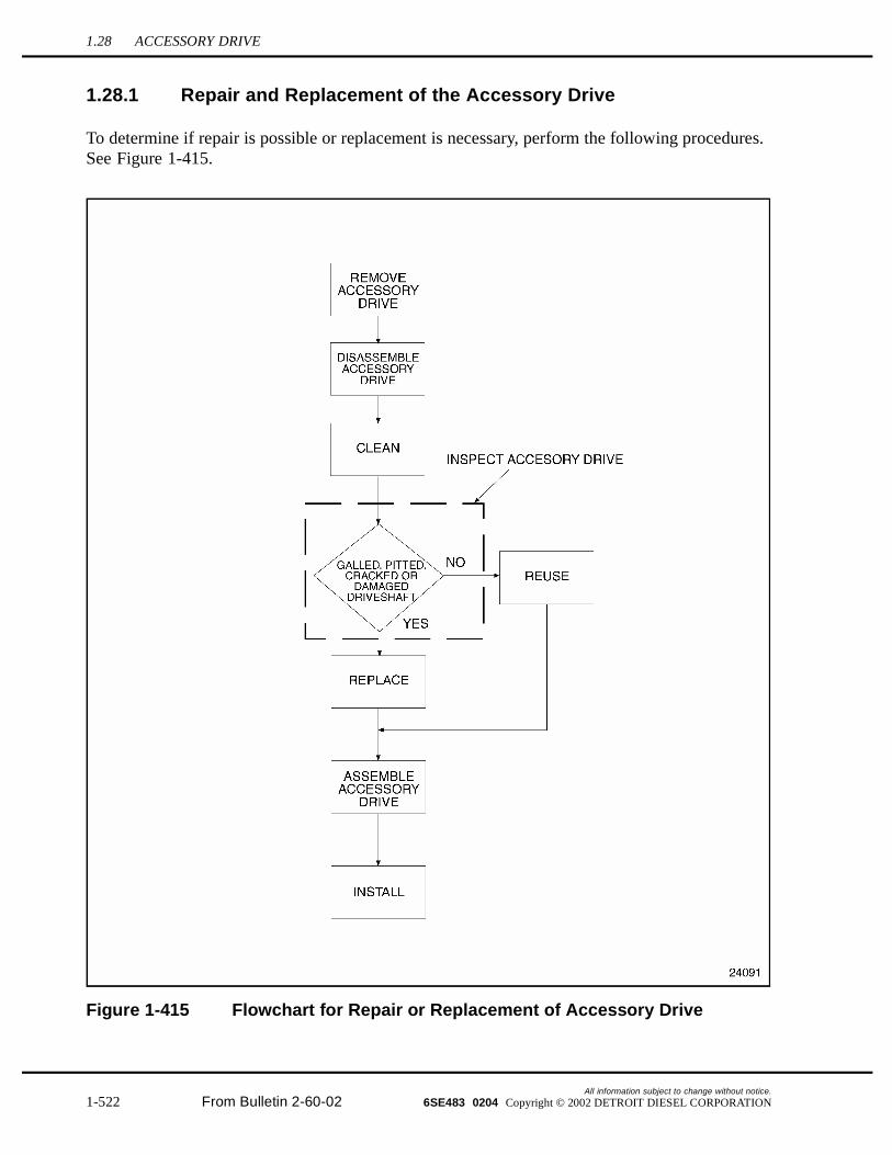
1.28.2 Removal and Cleaning of the Accessory Drive
Precleaning is not necessary.
Remove the accessory drive as follows:
1. Loosen the alternator mounting bolts and the adjusting rod nuts to get slack in thealternator drive belts. Remove the alternator drive belts. Refer to section 13.13.10.
2. Remove the five bolts that secure the accessory drive assembly to the gear case cover.
3. Remove the accessory drive assembly by pulling it straight out of the gear case cover toavoid damaging the rubber O-ring. See Figure 1-416.
Figure 1-416 Accessory Drive Assembly Removal
All information subject to change without notice.6SE483 0204 Copyright © 2002 DETROIT DIESEL CORPORATION From Bulletin 2-60-02 1-523

1.28 ACCESSORY DRIVE
1.28.3 Disassembly of the Accessory Drive
Disassemble the accessory drive as follows:
NOTE:For disassembly and assembly of the accessory drive use toolsetJ 36024–D. See Figure 1-417.
NOTE:Effective with engine serial number 6R631428, for accessory drive seal removal andinstallation use the following tools, J 45533 seal remover, J 45833 seal installer andJ 45877 seal runout gauge adapter to verify proper installation of seal in accessorydrive.These tools are part of toolset J 36024–D. See Figure 1-417.
Figure 1-417 Accessory Drive Service Tool Set J 36024–D
All information subject to change without notice.1-524 From Bulletin 2-60-02 6SE483 0204 Copyright © 2002 DETROIT DIESEL CORPORATION

SERIES 60 SERVICE MANUAL
1. Attach the accessory drive gear to the holding fixture, J 36024-3 (part of toolset J 36024–D) ,using the three bolts provided. See Figure 1-418.
Figure 1-418 Holding Fixture
All information subject to change without notice.6SE483 0204 Copyright © 2002 DETROIT DIESEL CORPORATION From Bulletin 2-60-02 1-525
1.28 ACCESSORY DRIVE
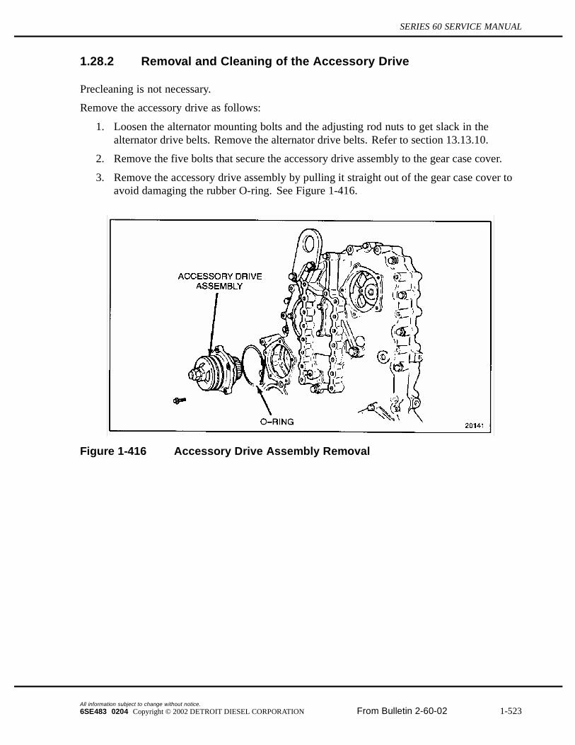
2. Place the accessory drive assembly holding fixture into a vise. See Figure 1-419.
Figure 1-419 Accessory Drive Pulley Locknut Removal
3. Remove the accessory drive pulley locknut. See Figure 1-419.
4. Remove the accessory drive pulley by tapping it with a rubber hammer or fiber mallet. Ifthe pulley does not come off easily, use a puller to remove it.
All information subject to change without notice.1-526 From Bulletin 2-60-02 6SE483 0204 Copyright © 2002 DETROIT DIESEL CORPORATION
SERIES 60 SERVICE MANUAL
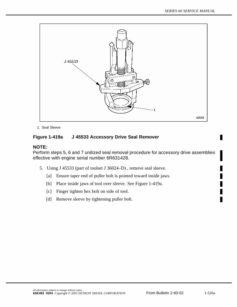
1. Seal Sleeve
Figure 1-419a J 45533 Accessory Drive Seal Remover
NOTE:Perform steps 5, 6 and 7 unitized seal removal procedure for accessory drive assemblieseffective with engine serial number 6R631428.
5. Using J 45533 (part of toolset J 36024–D) , remove seal sleeve.
[a] Ensure taper end of puller bolt is pointed toward inside jaws.
[b] Place inside jaws of tool over sleeve. See Figure 1-419a.
[c] Finger tighten hex bolt on side of tool.
[d] Remove sleeve by tightening puller bolt.
All information subject to change without notice.6SE483 0204 Copyright © 2002 DETROIT DIESEL CORPORATION From Bulletin 2-60-02 1-526a

1.28 ACCESSORY DRIVE
6. Removal of seal.
[a] Invert puller bolt. See Figure 1-419b.
Figure 1-419b J 45533 Invert Puller Bolt
[b] Loosen hex bolt on side of tool.
[c] Using a rubber mallet, gently drive outside jaws between seal and shaft through therubber membrane of seal until tool bottoms out.
[d] Finger tighten hex bolt on side of tool.
[e] Remove seal by tightening puller bolt.
7. Clean accessory drive housing at seal location.
All information subject to change without notice.1-526b From Bulletin 2-60-02 6SE483 0204 Copyright © 2002 DETROIT DIESEL CORPORATION

SERIES 60 SERVICE MANUAL
8. Position the accessory drive assembly on a press bed with the holding fixture supported.See Figure 1-420.
Figure 1-420 Accessory Drive Gear Removal
9. Using a press, apply pressure through the access hole in the holding fixtureJ 36024-3 (part of toolset J 36024–D), and press the drive shaft out of the gear.See Figure 1-420.
All information subject to change without notice.6SE483 0204 Copyright © 2002 DETROIT DIESEL CORPORATION From Bulletin 2-60-02 1-527

1.28 ACCESSORY DRIVE
10. Remove the snap ring from the accessory drive housing. See Figure 1-421.
Figure 1-421 Snap Ring Removal
11. Turn the housing over and support the accessory drive housing on the machined surfaceusing V-blocks.
12. Using a press, apply pressure to the pulley end of the shaft and remove the shaft andbearing assembly.
13. Turn the accessory drive housing over, and support it on the attaching bolt bosses usingV-blocks.
NOTE:On current design, the shaft serves as the inner race for the needle bearing.
All information subject to change without notice.1-528 From Bulletin 2-60-02 6SE483 0204 Copyright © 2002 DETROIT DIESEL CORPORATION
SERIES 60 SERVICE MANUAL
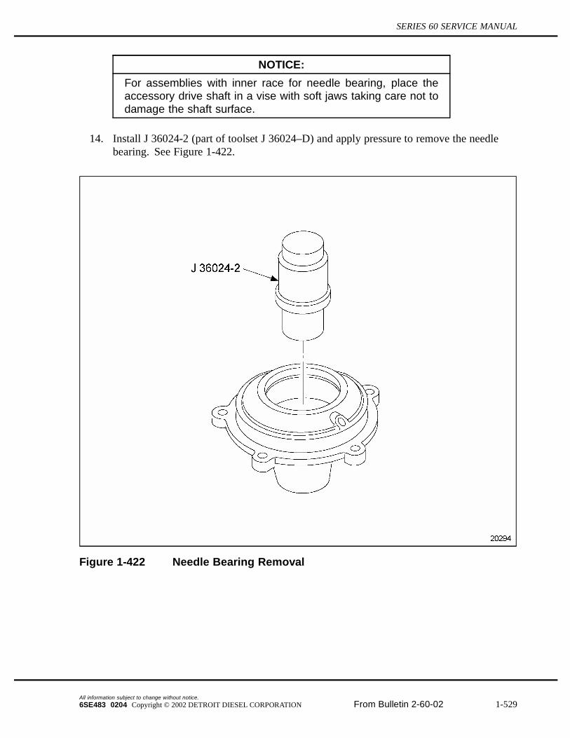
NOTICE:For assemblies with inner race for needle bearing, place theaccessory drive shaft in a vise with soft jaws taking care not todamage the shaft surface.
14. Install J 36024-2 (part of toolset J 36024–D) and apply pressure to remove the needlebearing. See Figure 1-422.
Figure 1-422 Needle Bearing Removal
All information subject to change without notice.6SE483 0204 Copyright © 2002 DETROIT DIESEL CORPORATION From Bulletin 2-60-02 1-529
1.28 ACCESSORY DRIVE
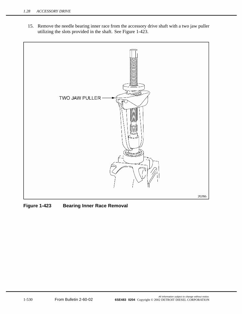
15. Remove the needle bearing inner race from the accessory drive shaft with a two jaw pullerutilizing the slots provided in the shaft. See Figure 1-423.
Figure 1-423 Bearing Inner Race Removal
All information subject to change without notice.1-530 From Bulletin 2-60-02 6SE483 0204 Copyright © 2002 DETROIT DIESEL CORPORATION
SERIES 60 SERVICE MANUAL
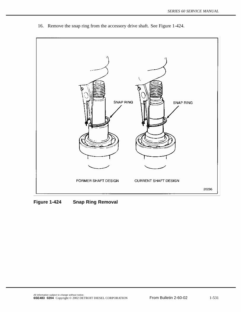
16. Remove the snap ring from the accessory drive shaft. See Figure 1-424.
Figure 1-424 Snap Ring Removal
All information subject to change without notice.6SE483 0204 Copyright © 2002 DETROIT DIESEL CORPORATION From Bulletin 2-60-02 1-531

1.28 ACCESSORY DRIVE
17. Position two steel press plates under the ball bearing outer race. See Figure 1-425.
Figure 1-425 Position of the Steel Press Plates
NOTE:Whenever the needle or ball bearing is removed from the shaft, they MUST be replacedwith new bearing assemblies.
18. Use a press to apply pressure to the top of the shaft and remove the ball bearing fromthe shaft.
All information subject to change without notice.1-532 From Bulletin 2-60-02 6SE483 0204 Copyright © 2002 DETROIT DIESEL CORPORATION
SERIES 60 SERVICE MANUAL
1.28.3.1 Inspection of the Accessory Drive
Clean the accessory drive prior to inspection as follows:
1. Clean all of the parts with clean fuel oil.
To avoid injury from flying debris when using compressedair, wear adequate eye protection (face shield or safetygoggles) and do not exceed 40 psi (276 kPa) air pressure.
2. Dry parts with compressed air.
Inspect the accessory drive as follows:
1. Visually examine the drive shaft for damage check the drive shaft for galling, pitting,cracks, or other damage.
[a] If any damage is detected, replace with a new part.
[b] If no damage is found, reuse the part.
All information subject to change without notice.6SE483 0204 Copyright © 2002 DETROIT DIESEL CORPORATION From Bulletin 2-60-02 1-533

1.28 ACCESSORY DRIVE
1.28.4 Assembly of the Accessory Drive
Assemble the accessory drive as follows:
1. Place a new ball bearing on the accessory drive shaft. Use toolJ 36024-1A (part of toolset J 36024–D) and a press to install the bearing onto the shaftuntil it bottoms out against the shoulder of the drive shaft. See Figure 1-426.
Figure 1-426 Bearing Installation
All information subject to change without notice.1-534 From Bulletin 2-60-02 6SE483 0204 Copyright © 2002 DETROIT DIESEL CORPORATION

SERIES 60 SERVICE MANUAL
2. Install the snap ring to the accessory drive shaft making sure it is fully seated in thegroove a full 360 degrees See Figure 1-427.
Figure 1-427 Snap Ring Installation
All information subject to change without notice.6SE483 0204 Copyright © 2002 DETROIT DIESEL CORPORATION From Bulletin 2-60-02 1-535
1.28 ACCESSORY DRIVE
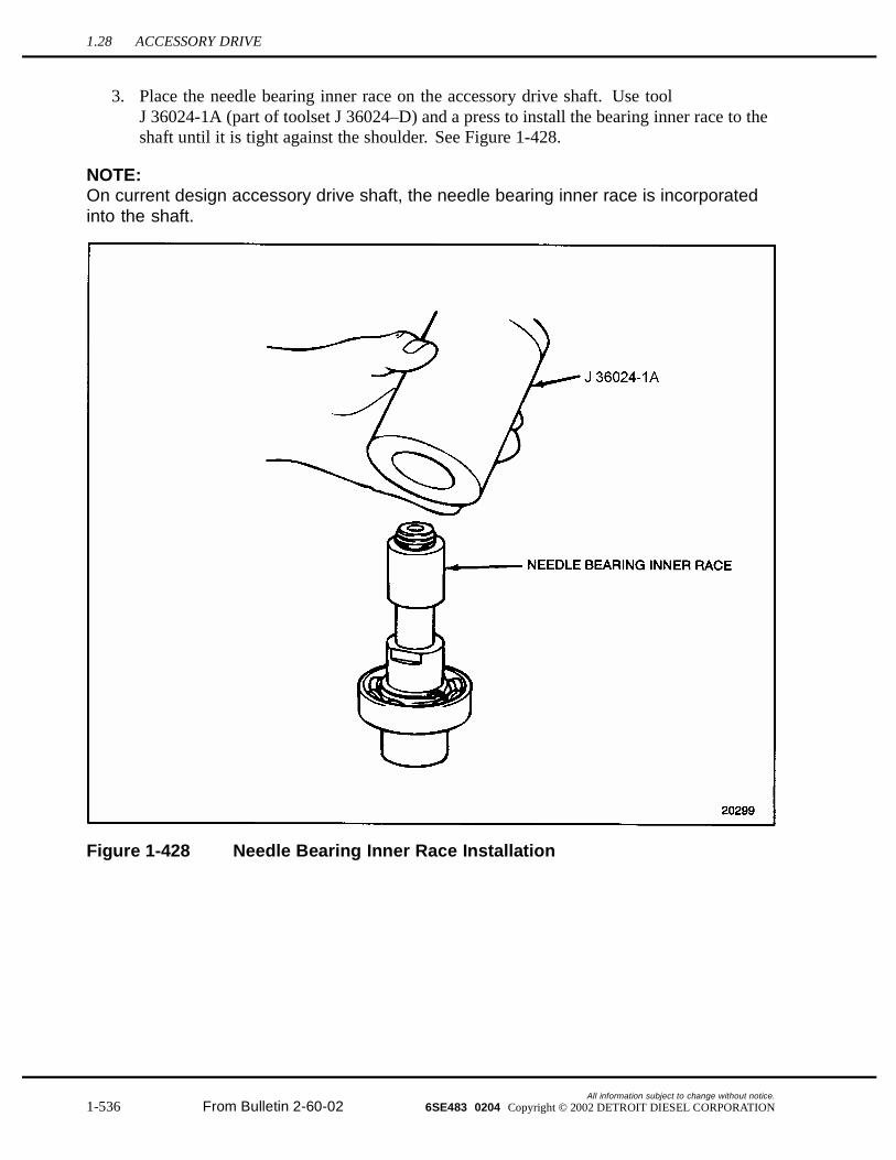
3. Place the needle bearing inner race on the accessory drive shaft. Use toolJ 36024-1A (part of toolset J 36024–D) and a press to install the bearing inner race to theshaft until it is tight against the shoulder. See Figure 1-428.
NOTE:On current design accessory drive shaft, the needle bearing inner race is incorporatedinto the shaft.
Figure 1-428 Needle Bearing Inner Race Installation
All information subject to change without notice.1-536 From Bulletin 2-60-02 6SE483 0204 Copyright © 2002 DETROIT DIESEL CORPORATION

SERIES 60 SERVICE MANUAL
4. Install the needle bearing to the accessory drive housing using toolJ 36024-2 (part of toolset J 36024–D). See Figure 1-429.
Figure 1-429 Needle Bearing Installation
NOTE:The end of the bearing with the identification numbers must be against the installer.
NOTE:The word INSTALL and an arrow are etched into the tool,J 36024-2 (part of toolset J 36024–D), to facilitate correct bearing installation.
All information subject to change without notice.6SE483 0204 Copyright © 2002 DETROIT DIESEL CORPORATION From Bulletin 2-60-02 1-537

1.28 ACCESSORY DRIVE
5. Lubricate the oil seal contact area of the accessory drive housing with a thin film ofengine oil.
6. Install the accessory drive oil seal to the accessory drive housing using the seal installer,J 36024-4 (part of toolset J 36024–D), and a plastic hammer or fiber mallet. The oilseal must be installed flush to 0.25 mm (0.010 in.) below the face of the housing.See Figure 1-430.
Figure 1-430 Accessory Drive Oil Seal Installation
7. Lubricate the oil seal with a thin film of engine oil.
8. Support the holding fixture, J 36024-3 (part of toolset J 36024–D) on two steel plates andposition the accessory drive housing into the hole in the fixture. See Figure 1-421.
All information subject to change without notice.1-538 From Bulletin 2-60-02 6SE483 0204 Copyright © 2002 DETROIT DIESEL CORPORATION

SERIES 60 SERVICE MANUAL
9. Install the drive shaft to the housing. See Figure 1-431.
Figure 1-431 Drive Shaft Installation
10. Press the drive shaft into the housing by placing tool,J 36024-1A (part of toolset J 36024–D) , on the bearing outer race.
All information subject to change without notice.6SE483 0204 Copyright © 2002 DETROIT DIESEL CORPORATION From Bulletin 2-60-02 1-539

1.28 ACCESSORY DRIVE
11. Press the bearing into the housing until the bearing is seated against the shoulder ofthe housing. See Figure 1-432.
Figure 1-432 Bearing Installation
All information subject to change without notice.1-540 From Bulletin 2-60-02 6SE483 0204 Copyright © 2002 DETROIT DIESEL CORPORATION

SERIES 60 SERVICE MANUAL
12. Install the snap ring to the accessory drive housing making sure the snap ring is fullyseated in the groove a full 360 degrees See Figure 1-433.
Figure 1-433 Snap Ring Installation
13. Lubricate the contact surfaces of the bearing with clean engine lubricating oil.
All information subject to change without notice.6SE483 0204 Copyright © 2002 DETROIT DIESEL CORPORATION From Bulletin 2-60-02 1-541
1.28 ACCESSORY DRIVE
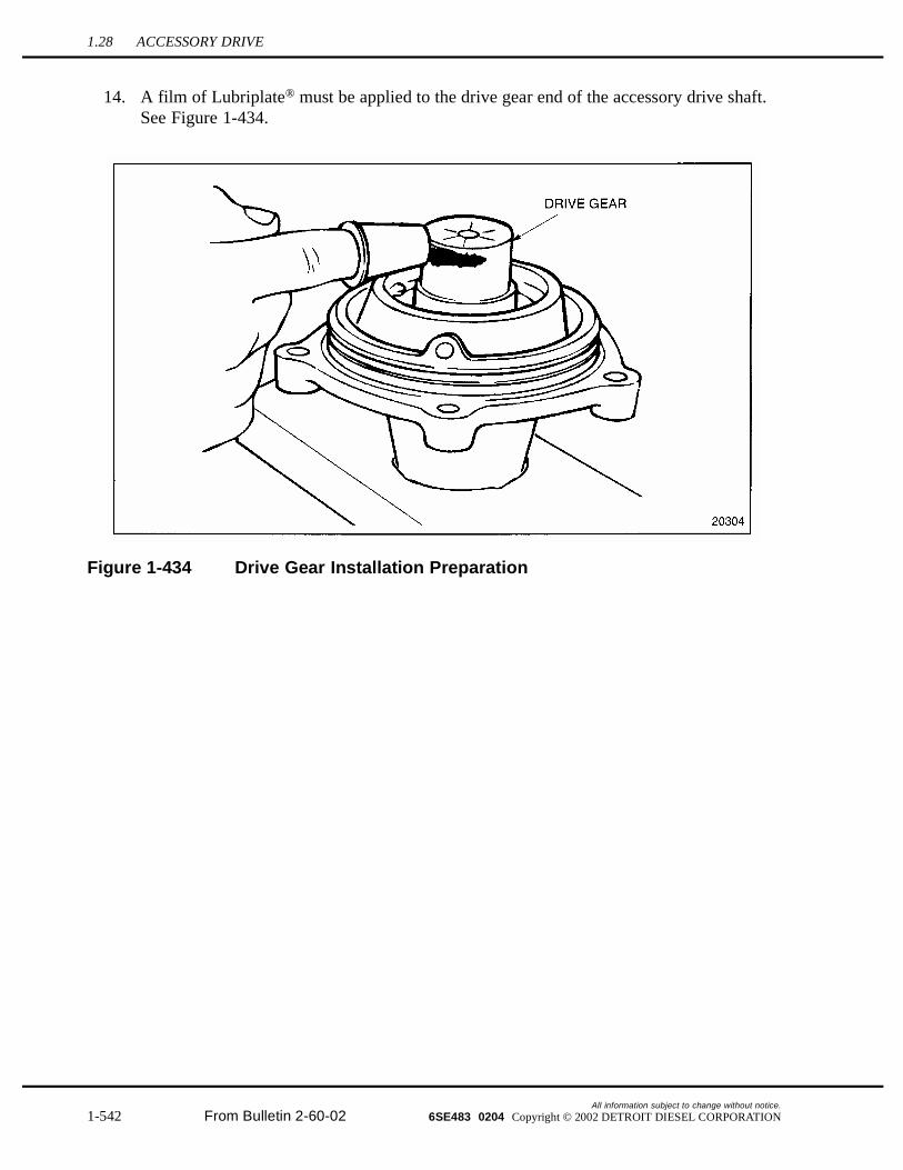
14. A film of Lubriplate® must be applied to the drive gear end of the accessory drive shaft.See Figure 1-434.
Figure 1-434 Drive Gear Installation Preparation
All information subject to change without notice.1-542 From Bulletin 2-60-02 6SE483 0204 Copyright © 2002 DETROIT DIESEL CORPORATION

SERIES 60 SERVICE MANUAL
15. Use a press to install the drive gear on the accessory drive shaft until it is flush with thedrive shaft end. Make sure the three threaded holes are facing up. See Figure 1-435.
NOTE:Support the opposite end of the drive shaft on the press bed when pressing the gear onthe shaft. A minimum press load of 17.8 kN (4000 lb) must be obtained when pressingthe gear on the shaft.
Figure 1-435 Accessory Drive Gear Installation
All information subject to change without notice.6SE483 0204 Copyright © 2002 DETROIT DIESEL CORPORATION From Bulletin 2-60-02 1-543

1.28 ACCESSORY DRIVE
NOTE:For accessory drive assemblies effective with engine serial number 6R631428 performthe procedures in steps 16 and 17.
16. Install seal using J 45833 (part of toolset J 36024–D) by tightening installer nut until apositive stop is obtained. See Figure 1-435a.
1. Vise
Figure 1-435a J 45833 Accessory Drive Seal Installer
All information subject to change without notice.1-543a From Bulletin 2-60-02 6SE483 0204 Copyright © 2002 DETROIT DIESEL CORPORATION

SERIES 60 SERVICE MANUAL
17. Measure sleeve and seal run out using J 45877 (part of toolset J 36024–D) and a dialindicator. Total indicator deflection should not exceed 0.0762 mm (0.003 in.) forthe sleeve and 0.1778 mm (0.007 in.) for the seal. If the run out is greater for eithermeasurement, install a new seal. See Figure 1-435b.
1. Dial Indicator 2. Seal Sleeve
Figure 1-435b J 45877 Seal Run Out Gauge Adaptor
18. Install the accessory drive pulley to the shaft.
NOTE:If necessary, use tool J 36024-1A (part of toolset J 36024–D) to seat the pulley on theshaft. If pressing is necessary, the opposite (gear) end of the shaft must be supportedduring the pressing operation.
19. Attach J 36024-3 (part of toolset J 36024–D), to the drive gear. See Figure 1-418.
20. Place the accessory drive assembly holding fixture into a vise. See Figure 1-436.
All information subject to change without notice.6SE483 0204 Copyright © 2002 DETROIT DIESEL CORPORATION From Bulletin 2-60-02 1-543b

1.28 ACCESSORY DRIVE
21. Install and torque the accessory drive pulley locknut to 360-400 N·m (266-295 lb·ft).See Figure 1-436.
Figure 1-436 Accessory Drive Pulley Locknut Tightening
All information subject to change without notice.1-544 From Bulletin 2-60-02 6SE483 0204 Copyright © 2002 DETROIT DIESEL CORPORATION

SERIES 60 SERVICE MANUAL
22. Support the accessory drive assembly. See Figure 1-437.
Figure 1-437 Accessory Drive Gear TIR Measurement
23. Assemble a dial indicator and magnetic base, so that the indicator stem rests on the face ofthe accessory drive gear just inboard of the drive gear teeth. See Figure 1-437.
24. Zero the dial indicator.
25. Rotate the drive gear two full rotations. See Figure 1-437. As the gear is rotated, the dialindicator needle may register both to the left and right of zero.
26. The total amount the dial indicator needle moves to the left and right of zero, addedtogether, gives the total indicated run-out (TIR). The specified TIR is 0.04 mm (0.0015 in.).
All information subject to change without notice.6SE483 0204 Copyright © 2002 DETROIT DIESEL CORPORATION From Bulletin 2-60-02 1-545

1.28 ACCESSORY DRIVE
1.28.5 Installation of the Accessory Drive
Install the accessory drive as follows:
1. Install the O-ring seal in the groove on the drive housing.
2. Lubricate the O-ring with petroleum jelly.
3. Install the accessory drive housing to its original position in the gear case cover.
NOTE:The word "UP" is cast into the drive housing.
4. Install the bolts that secure the accessory drive housing to the gear case cover and torqueto 30-38 N·m (22-28 lb·ft) using the pattern shown. See Figure 1-438.
Figure 1-438 Accessory Drive Housing Bolt Torque Sequence
5. Check the bull gear-to-accessory drive gear backlash. Refer to section 1.21.2.1.
6. Adjust the alternator belts. Refer to section 13.13.10.
7. Tighten the alternator mounting bolts.
8. Install any other components removed for this procedure.
9. Refer to section 11.3 for verification of proper accessory drive installation.
All information subject to change without notice.1-546 From Bulletin 2-60-02 6SE483 0204 Copyright © 2002 DETROIT DIESEL CORPORATION