128-9020 2011 Jeep Grand Cherokee SL Active … an Anti-theft radio, the radio code must be written...
14
JEEP / GRAND CHEROKEE / 2011 ADVENT HEADREST VIDEO © 2011 Advent All rights reserved. Page 1 of 14 128-9020 Document 128-9020 Created 11/21/11 Kit Contents: Item # Qty. Component Description 1 2 Headrest Assembly 2 2 Cables # 3 3 1 Power Cord # 9 4 1 FM Antenna 5 1 Control Box 6 2 IR Headphones 7 2 Remote Control 8 8 AAA Batteries 9 1 Owners Manual 10 1 Wire Puller 11 1 Hardware Bag 12 4 Post Covers Hardware Bag Contents: Item # Qty. Component Description 1 2 Red T-Taps 2 1 4” X 8” Foam Tape 3 12 6” Wire Ties 4 2 11” Wire Ties 5 4 Cable Clamps 6 1 6ft 3.5mm Audio Cable Additional Items Required For Installation: Item # Qty. Component Description 1 Masking Tape 2 Electrical Tape Recommended Tools: Safety Tools Seat/ Floor Covers Blankets Special Tools None Installation Tools NRT (Nylon Removal Tool) Pliers Wire Cutters Pencil Pick Tool Ratchet Special Chemicals None Color Applicability/ Trim Level: Vehicle Trim Color Trim Level Laredo Limited Overland Medium Graystone X Black X X X Light frost Beige X Dark Frost Beige X Saddle X General Applicability: Jeep Grand Cherokee Active LEGEND: STOP: Damage to the vehicle may occur. Do not proceed until process has been complied with. OPERATOR SAFETY: Use caution to avoid risk of injury. CRITICAL PROCESS: Proceed with caution to ensure a quality installation. These points will be audited on a completed vehicle installation. TOOLS & EQUIPMENT: This calls out the specific tools and equipment required for this process. REVISION MARK: This mark highlights a change in installation with respect to previous issue. INSTRUCTION/ INSTALLATION NOTES: After Safety mandated preparatory steps have been taken, the installation sequence is the suggested method for completing the accessory installation. When prying panels, use masking tape on all surfaces that a tool may come in contact with to prevent marring. After a wire tie is fully fastened, cleanly cut excess wire tie length with a pair of wire cutters. The wiring information is on an “as is” basis without any representation or warranty. It is the installer’s responsibility to verify any circuit before interfacing with it using a digital multimeter. Manufacturer’s service documents can be used for any vehicle disassembly that may be depicted differently from what the instruction states. Use Wiring Diagram on last page of document to clarify cable or component names. If technical support is required, please contact Advent Technical Support at 1-800-323-4815.
Transcript of 128-9020 2011 Jeep Grand Cherokee SL Active … an Anti-theft radio, the radio code must be written...

JEEP / GRAND CHEROKEE / 2011 ADVENT HEADREST VIDEO
© 2011 Advent All rights reserved. Page 1 of 14 128-9020
Document 128-9020 Created 11/21/11
Kit Contents: Item # Qty. Component Description
1 2 Headrest Assembly 2 2 Cables # 3 3 1 Power Cord # 9 4 1 FM Antenna 5 1 Control Box 6 2 IR Headphones 7 2 Remote Control 8 8 AAA Batteries 9 1 Owners Manual 10 1 Wire Puller 11 1 Hardware Bag 12 4 Post Covers
Hardware Bag Contents:
Item # Qty. Component Description 1 2 Red T-Taps 2 1 4” X 8” Foam Tape 3 12 6” Wire Ties 4 2 11” Wire Ties 5 4 Cable Clamps 6 1 6ft 3.5mm Audio Cable
Additional Items Required For Installation:
Item # Qty. Component Description 1 Masking Tape 2 Electrical Tape
Recommended Tools:
Safety Tools Seat/ Floor Covers Blankets Special Tools None Installation Tools NRT (Nylon Removal Tool) Pliers Wire Cutters Pencil Pick Tool Ratchet Special Chemicals None
Color Applicability/ Trim Level:
Vehicle Trim Color
Trim
Level
Laredo
Limite
d
Overland
Medium Graystone X Black X X X Light frost Beige X Dark Frost Beige X Saddle X
General Applicability: Jeep Grand Cherokee Active
LEGEND:
STOP: Damage to the vehicle may occur. Do not proceed until process has been complied with.
OPERATOR SAFETY: Use caution to avoid risk of injury.
CRITICAL PROCESS: Proceed with caution to ensure a quality installation. These points will be audited on a completed vehicle installation. TOOLS & EQUIPMENT: This calls out the specific tools and equipment required for this process.
REVISION MARK: This mark highlights a change in installation with respect to previous issue.
INSTRUCTION/ INSTALLATION NOTES: After Safety mandated preparatory steps have been taken,
the installation sequence is the suggested method for completing the accessory installation.
When prying panels, use masking tape on all surfaces that a tool may come in contact with to prevent marring.
After a wire tie is fully fastened, cleanly cut excess wire tie length with a pair of wire cutters.
The wiring information is on an “as is” basis without any representation or warranty. It is the installer’s responsibility to verify any circuit before interfacing with it using a digital multimeter.
Manufacturer’s service documents can be used for any vehicle disassembly that may be depicted differently from what the instruction states.
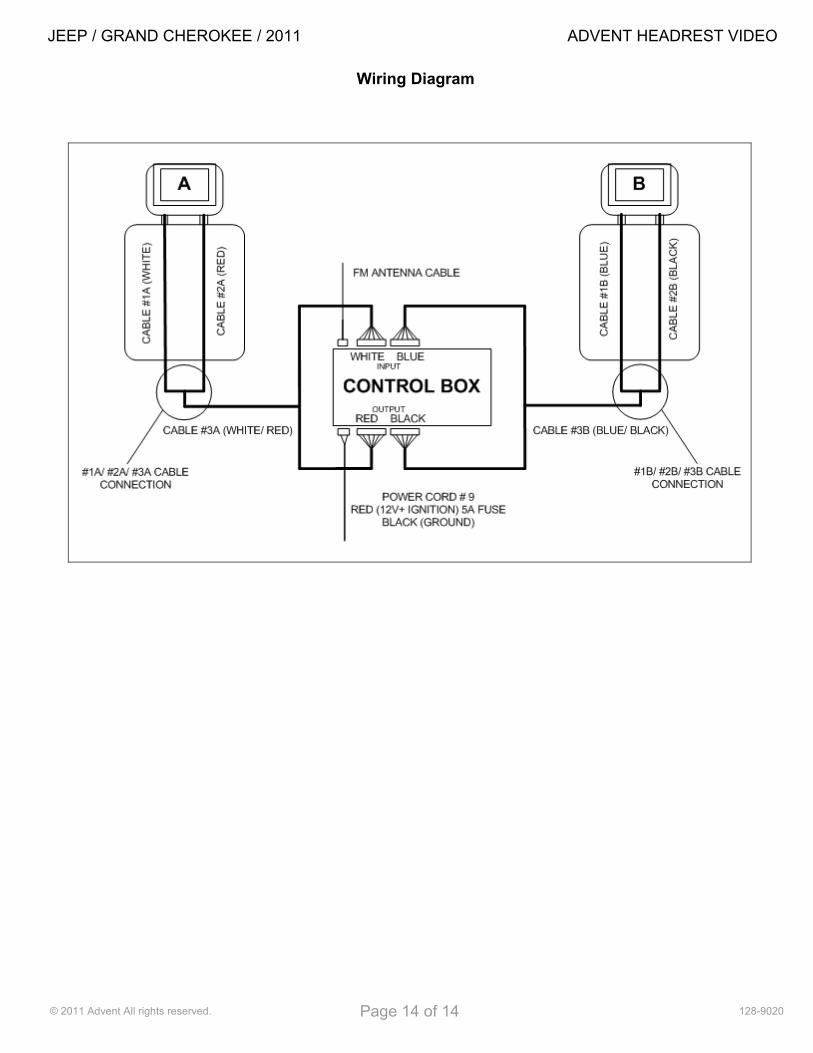
Use Wiring Diagram on last page of document to clarify cable or component names.
If technical support is required, please contact Advent Technical Support at 1-800-323-4815.
JEEP / GRAND CHEROKEE / 2011 ADVENT HEADREST VIDEO
© 2011 Advent All rights reserved. Page 2 of 14 128-9020
A. Pre-Installation Precaution
1. Use Seat and Floor protectors to avoid damage
to surfaces.
Disconnecting the battery prior to any ground or harness removal/ tapping to prevent possible vehicle damage is recommended. The battery may be temporarily reconnected and disconnected throughout the installation process to perform various tasks. However prior to doing so all connectors and harnesses must be reassembled and reconnected. Once tasks are completed disconnect battery until installation is complete and DVD system is ready to be tested. After testing, the vehicles interior may be re-assembled. If the vehicle is equipped with an Anti-theft radio, the code must be written down prior to disconnecting the battery cable. The code must be re-entered when the negative battery cable is re-installed. Disconnecting the battery may cause certain vehicle settings to be lost. Manufacturer’s recommendations for the battery removal should be followed.
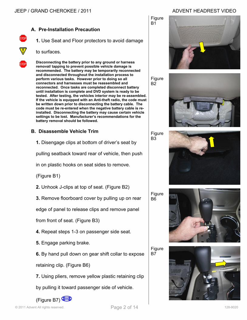
B. Disassemble Vehicle Trim
1. Disengage clips at bottom of driver’s seat by
pulling seatback toward rear of vehicle, then push
in on plastic hooks on seat sides to remove.
(Figure B1)
2. Unhook J-clips at top of seat. (Figure B2)
3. Remove floorboard cover by pulling up on rear
edge of panel to release clips and remove panel
from front of seat. (Figure B3)
4. Repeat steps 1-3 on passenger side seat.
5. Engage parking brake.
6. By hand pull down on gear shift collar to expose
retaining clip. (Figure B6)
7. Using pliers, remove yellow plastic retaining clip
by pulling it toward passenger side of vehicle.
(Figure B7)
Figure B1 Figure B2 Figure B3 Figure B6 Figure B7

JEEP / GRAND CHEROKEE / 2011 ADVENT HEADREST VIDEO
© 2011 Advent All rights reserved. Page 3 of 14 128-9020
8. Remove gear selector by pulling up. (Figure B8)
9. Open both center console and front console
compartments.
10. Pull up on center console trim from rear and
work forward. (Figure B10)
11. Disconnect electrical connector. (Figure B11)
12. Remove radio/ climate control trim bezel by
pulling toward rear of vehicle. (Figure B12)
13. Disconnect electrical connectors. (Figure B13)
Figure B8 Figure B10 Figure B11 Figure B12 Figure B13
JEEP / GRAND CHEROKEE / 2011 ADVENT HEADREST VIDEO
© 2011 Advent All rights reserved. Page 4 of 14 128-9020
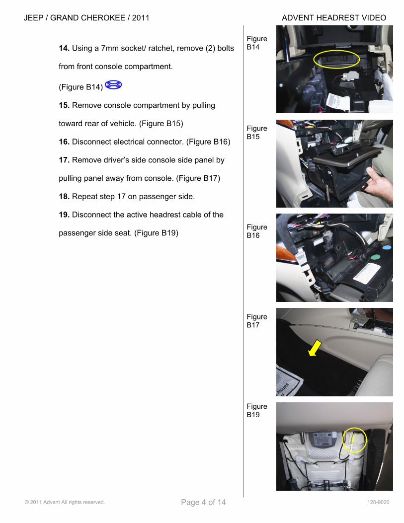
14. Using a 7mm socket/ ratchet, remove (2) bolts
from front console compartment.
(Figure B14)
15. Remove console compartment by pulling
toward rear of vehicle. (Figure B15)
16. Disconnect electrical connector. (Figure B16)
17. Remove driver’s side console side panel by
pulling panel away from console. (Figure B17)
18. Repeat step 17 on passenger side.
19. Disconnect the active headrest cable of the
passenger side seat. (Figure B19)
Figure B14 Figure B15 Figure B16 Figure B17 Figure B19
JEEP / GRAND CHEROKEE / 2011 ADVENT HEADREST VIDEO
© 2011 Advent All rights reserved. Page 5 of 14 128-9020
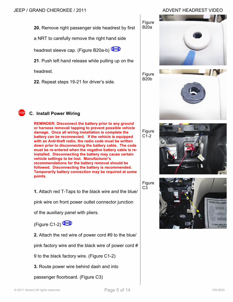
20. Remove right passenger side headrest by first
a NRT to carefully remove the right hand side
headrest sleeve cap. (Figure B20a-b)
21. Push left hand release while pulling up on the
headrest.
22. Repeat steps 19-21 for driver’s side.
C. Install Power Wiring
REMINDER: Disconnect the battery prior to any ground or harness removal/ tapping to prevent possible vehicle damage. Once all wiring installation is complete the battery can be reconnected. If the vehicle is equipped with an Anti-theft radio, the radio code must be written down prior to disconnecting the battery cable. The code must be re-entered when the negative battery cable is re-installed. Disconnecting the battery may cause certain vehicle settings to be lost. Manufacturer’s recommendations for the battery removal should be followed. Disconnecting the battery is recommended. Temporarily battery connection may be required at some points.
1. Attach red T-Taps to the black wire and the blue/
pink wire on front power outlet connector junction
of the auxiliary panel with pliers.
(Figure C1-2)
2. Attach the red wire of power cord #9 to the blue/
pink factory wire and the black wire of power cord #
9 to the black factory wire. (Figure C1-2)
3. Route power wire behind dash and into
passenger floorboard. (Figure C3)
Figure B20a Figure B20b Figure C1-2 Figure C3

JEEP / GRAND CHEROKEE / 2011 ADVENT HEADREST VIDEO
© 2011 Advent All rights reserved. Page 6 of 14 128-9020
D. Mount Control Box
1. Make all connections to the control box using
color coded connections including antenna and
power cord # 9. (Figure D1)
2. Wrap control box in foam tape. (Figure D2)
3. Route cable #3A (red and white) from passenger
floorboard through console and into driver
floorboard area. (Figure D3a-b)
Figure D1 Figure D2 Figure D3a Figure D3b

JEEP / GRAND CHEROKEE / 2011 ADVENT HEADREST VIDEO
© 2011 Advent All rights reserved. Page 7 of 14 128-9020
4. Once cables #3A are fully pulled to driver’s side,
wedge control box from passenger side below front
console compartment area. (Figure D4a-b)
5. Secure excess power cord and fuse holder to
factory wiring with (1) 6” wire tie and tuck into dash
cavity. (Figure D5)
E. Route Headrest Cables
1. Route cable #3A toward slit in carpet below
driver’s side seat. Tuck cable into carpet.
(Figure E1)
2. Continue to tuck cables under carpet at slit area.
(Figure E2)
3. Pull cable through to under side of seat.
4. Repeat steps 1-3 with cables #3B (blue and
black) on passenger side.
Figure D4a Figure D4b Figure D5 Figure E1 Figure E2
JEEP / GRAND CHEROKEE / 2011 ADVENT HEADREST VIDEO
© 2011 Advent All rights reserved. Page 8 of 14 128-9020
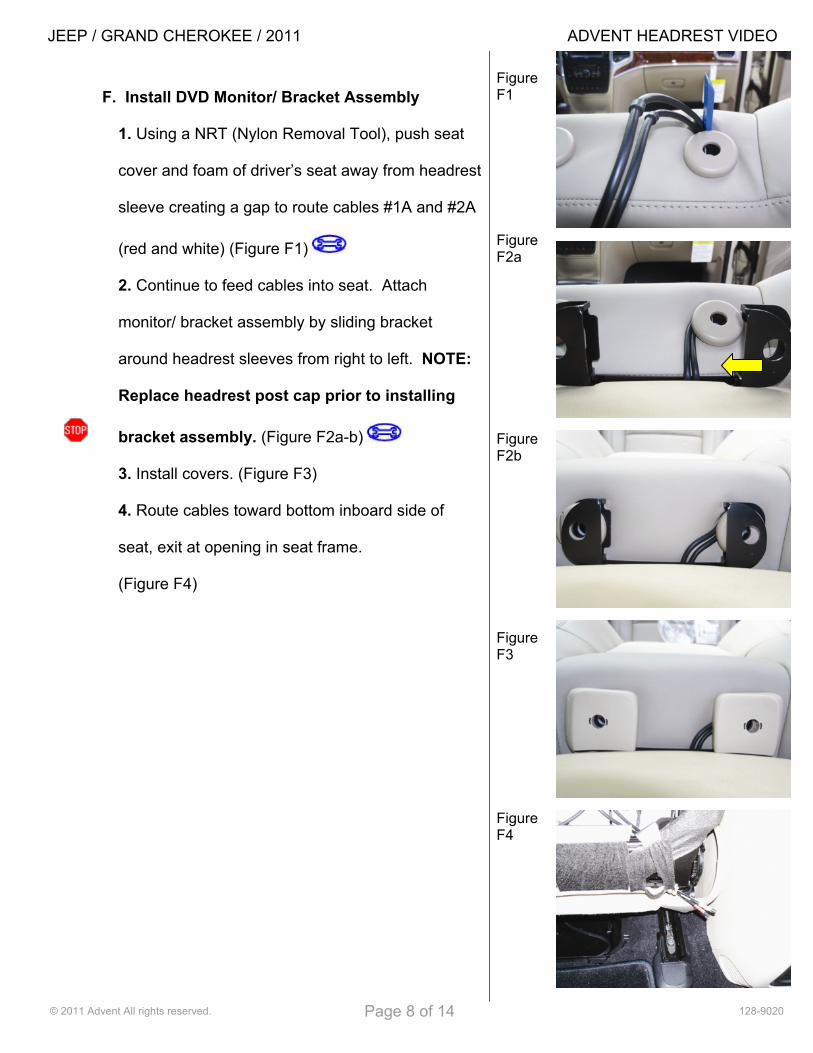
F. Install DVD Monitor/ Bracket Assembly
1. Using a NRT (Nylon Removal Tool), push seat
cover and foam of driver’s seat away from headrest
sleeve creating a gap to route cables #1A and #2A
(red and white) (Figure F1)
2. Continue to feed cables into seat. Attach
monitor/ bracket assembly by sliding bracket
around headrest sleeves from right to left. NOTE:
Replace headrest post cap prior to installing
bracket assembly. (Figure F2a-b)
3. Install covers. (Figure F3)
4. Route cables toward bottom inboard side of
seat, exit at opening in seat frame.
(Figure F4)
Figure F1 Figure F2a Figure F2b Figure F3 Figure F4

JEEP / GRAND CHEROKEE / 2011 ADVENT HEADREST VIDEO
© 2011 Advent All rights reserved. Page 9 of 14 128-9020
5. Continue to route cables to bottom side of seat
behind molding. (Figure F5)
6. Connect cables # 1A and # 2A to cable # 3A.
(Figure F6)
7. Snap security clamp around each connection
point between cables #1A and #2A to cable #3A,
add wire tie to strain relief, and apply foam tape.
(Figure F7)
8. Secure cables under seat using (3) 6” wire ties
to the factory wiring on each side of cable clamps.
(Figure F8)
9. Secure cables in back of seat with (1) 6” wire tie.
(Figure F9)
10. Verify motion of seat travel. Check that cables
are not near seat tracks and that they move freely
with the seat without any stress.
11. Repeat steps 1-10 with cables # 1B, # 2B, and
# 3B on the passenger side seat.
Figure F5 Figure F6 Figure F7 Figure F8 Figure F9
JEEP / GRAND CHEROKEE / 2011 ADVENT HEADREST VIDEO
© 2011 Advent All rights reserved. Page 10 of 14 128-9020
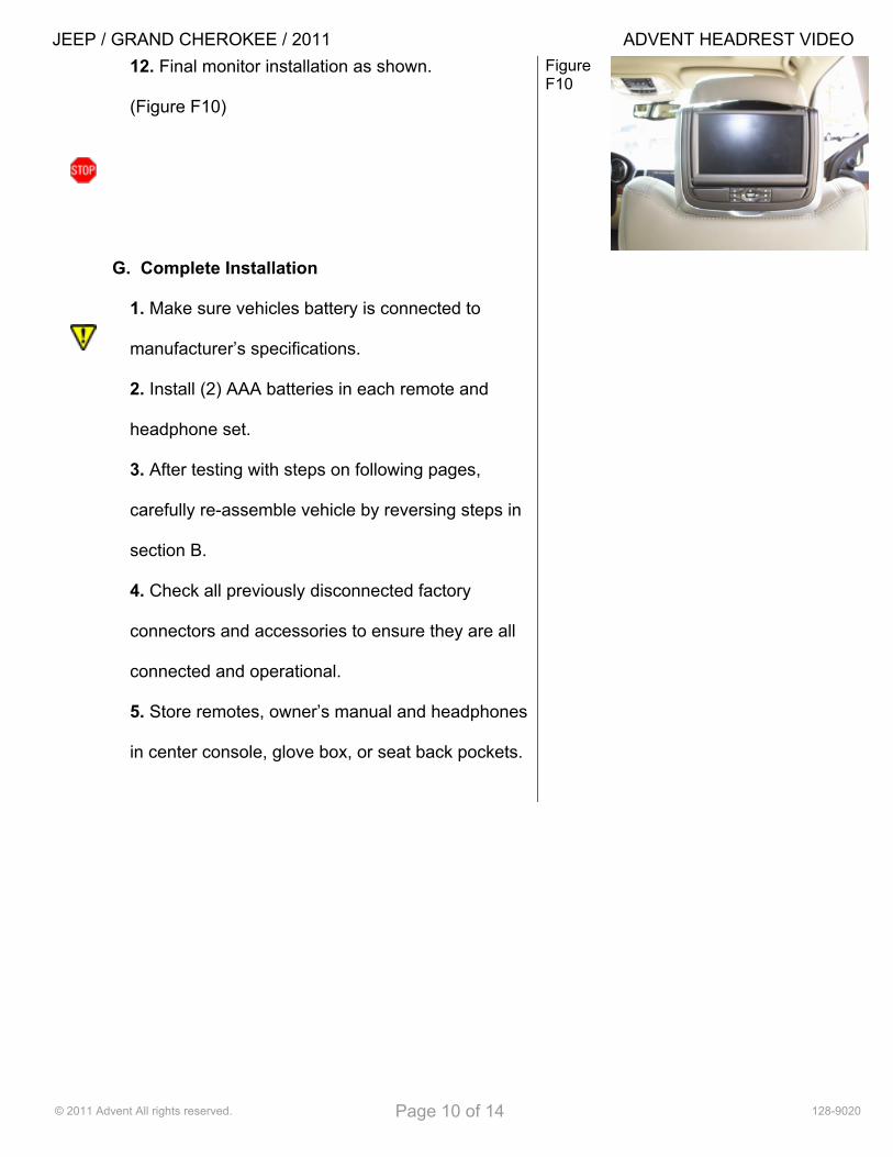
12. Final monitor installation as shown.
(Figure F10)
G. Complete Installation
1. Make sure vehicles battery is connected to
manufacturer’s specifications.
2. Install (2) AAA batteries in each remote and
headphone set.
3. After testing with steps on following pages,
carefully re-assemble vehicle by reversing steps in
section B.
4. Check all previously disconnected factory
connectors and accessories to ensure they are all
connected and operational.
5. Store remotes, owner’s manual and headphones
in center console, glove box, or seat back pockets.
Figure F10
JEEP / GRAND CHEROKEE / 2011 ADVENT HEADREST VIDEO
© 2011 Advent All rights reserved. Page 11 of 14 128-9020
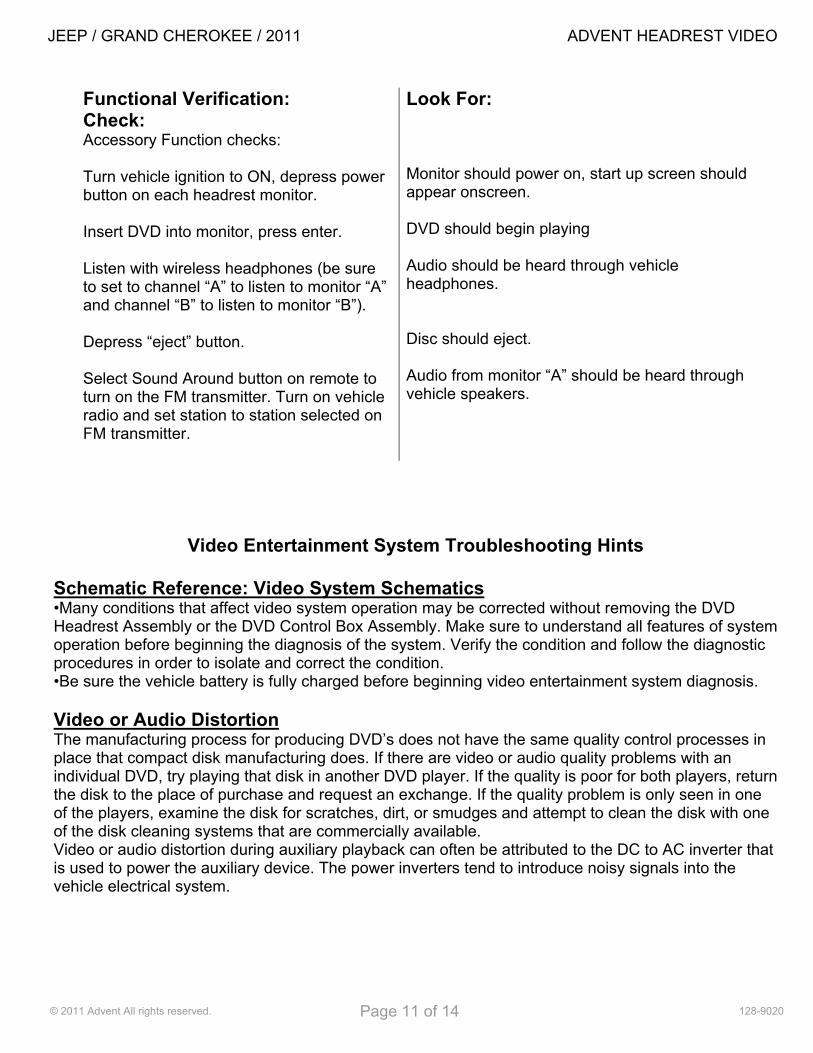
Functional Verification: Check: Accessory Function checks: Turn vehicle ignition to ON, depress power button on each headrest monitor. Insert DVD into monitor, press enter. Listen with wireless headphones (be sure to set to channel “A” to listen to monitor “A” and channel “B” to listen to monitor “B”). Depress “eject” button. Select Sound Around button on remote to turn on the FM transmitter. Turn on vehicle radio and set station to station selected on FM transmitter.
Look For: Monitor should power on, start up screen should appear onscreen. DVD should begin playing Audio should be heard through vehicle headphones. Disc should eject. Audio from monitor “A” should be heard through vehicle speakers.
Video Entertainment System Troubleshooting Hints
Schematic Reference: Video System Schematics •Many conditions that affect video system operation may be corrected without removing the DVD Headrest Assembly or the DVD Control Box Assembly. Make sure to understand all features of system operation before beginning the diagnosis of the system. Verify the condition and follow the diagnostic procedures in order to isolate and correct the condition. •Be sure the vehicle battery is fully charged before beginning video entertainment system diagnosis. Video or Audio Distortion The manufacturing process for producing DVD’s does not have the same quality control processes in place that compact disk manufacturing does. If there are video or audio quality problems with an individual DVD, try playing that disk in another DVD player. If the quality is poor for both players, return the disk to the place of purchase and request an exchange. If the quality problem is only seen in one of the players, examine the disk for scratches, dirt, or smudges and attempt to clean the disk with one of the disk cleaning systems that are commercially available. Video or audio distortion during auxiliary playback can often be attributed to the DC to AC inverter that is used to power the auxiliary device. The power inverters tend to introduce noisy signals into the vehicle electrical system.
JEEP / GRAND CHEROKEE / 2011 ADVENT HEADREST VIDEO
© 2011 Advent All rights reserved. Page 12 of 14 128-9020
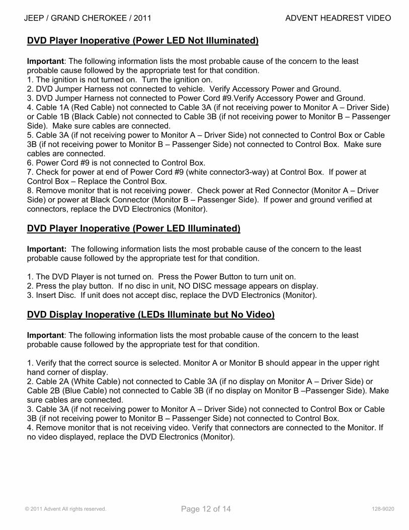
DVD Player Inoperative (Power LED Not Illuminated) Important: The following information lists the most probable cause of the concern to the least probable cause followed by the appropriate test for that condition. 1. The ignition is not turned on. Turn the ignition on. 2. DVD Jumper Harness not connected to vehicle. Verify Accessory Power and Ground. 3. DVD Jumper Harness not connected to Power Cord #9.Verify Accessory Power and Ground. 4. Cable 1A (Red Cable) not connected to Cable 3A (if not receiving power to Monitor A – Driver Side) or Cable 1B (Black Cable) not connected to Cable 3B (if not receiving power to Monitor B – Passenger Side). Make sure cables are connected. 5. Cable 3A (if not receiving power to Monitor A – Driver Side) not connected to Control Box or Cable 3B (if not receiving power to Monitor B – Passenger Side) not connected to Control Box. Make sure cables are connected. 6. Power Cord #9 is not connected to Control Box. 7. Check for power at end of Power Cord #9 (white connector3-way) at Control Box. If power at Control Box – Replace the Control Box. 8. Remove monitor that is not receiving power. Check power at Red Connector (Monitor A – Driver Side) or power at Black Connector (Monitor B – Passenger Side). If power and ground verified at connectors, replace the DVD Electronics (Monitor). DVD Player Inoperative (Power LED Illuminated) Important: The following information lists the most probable cause of the concern to the least probable cause followed by the appropriate test for that condition. 1. The DVD Player is not turned on. Press the Power Button to turn unit on. 2. Press the play button. If no disc in unit, NO DISC message appears on display. 3. Insert Disc. If unit does not accept disc, replace the DVD Electronics (Monitor). DVD Display Inoperative (LEDs Illuminate but No Video) Important: The following information lists the most probable cause of the concern to the least probable cause followed by the appropriate test for that condition. 1. Verify that the correct source is selected. Monitor A or Monitor B should appear in the upper right hand corner of display. 2. Cable 2A (White Cable) not connected to Cable 3A (if no display on Monitor A – Driver Side) or Cable 2B (Blue Cable) not connected to Cable 3B (if no display on Monitor B –Passenger Side). Make sure cables are connected. 3. Cable 3A (if not receiving power to Monitor A – Driver Side) not connected to Control Box or Cable 3B (if not receiving power to Monitor B – Passenger Side) not connected to Control Box. 4. Remove monitor that is not receiving video. Verify that connectors are connected to the Monitor. If no video displayed, replace the DVD Electronics (Monitor).

JEEP / GRAND CHEROKEE / 2011 ADVENT HEADREST VIDEO
© 2011 Advent All rights reserved. Page 13 of 14 128-9020
Cannot Hear Audio Through Vehicle Speakers(FM Transmitter Inoperative) Important: The following information lists the most probable cause of the concern to the least probable cause followed by the appropriate test for that condition. 1. FM Transmitter not turned on. Turn on FM Transmitter using the Remote Control. Press the DVD Button (A) on the Remote Control to control Monitor A – Driver Side Headrest. Press the Sound Around On/Off Button. “CH On” should appear on Monitor A display. 2. Radio and DVD Unit are not set to the same FM Frequency. Press the Sound Around Select button to select a frequency (88.3 MHz, 88.7 MHz, 89.1 MHz, 89.5 MHz, 89.9 MHz, or90.3 MHz). The frequency should appear on Monitor A display in upper right hand corner. Tune the Radio to the frequency selected. If no DVD audio over speakers, verify audio by selecting another radio frequency. Replace the DVD Control Box. Video Entertainment System Wireless Headphone Inoperative Important: The following information lists the most probable cause of the concern to the least probable cause followed by the appropriate test for that condition. 1. Volume control on the wireless headphone set is turned all the way down. Adjust the volume control on the headphones. 2. Incorrect Channel Selected. To hear audio from Monitor A– Driver Side select Channel A. To hear audio from Monitor B – Passenger Side select Channel B. 3. Dead batteries or batteries placed incorrectly in the wireless headphone set. Turn on power to the headphone set. If the headset indicator does not turn on; place batteries in correctly or replace the batteries in the headset as needed. 4. Make sure headphone is in line of sight and no obstructions of the Monitor being listened from. 5. Faulty headphone set. Test the operation of the system using a known good headphone set. If operation is OK, replace the faulty headphone set. 6. Inoperative infrared transmitter in the (DVD) Monitor (s)--Replace the DVD Electronics. Video Entertainment System Remote Control Inoperative The buttons on the video remote control do not operate the videodisc player but the buttons on the DVD Headrest Monitor Control Panel operate normally. Important: The following information lists the most probable cause of the concern to the least probable cause followed by the appropriate test for that condition. 1. Press DVD A button to control Monitor A or press DVD B button to control Monitor B. 2. Dead batteries or batteries placed incorrectly in the video remote control. Place batteries in correctly or replace the dead batteries as needed. 3. Faulty remote control. Test the operation of the system using a known good remote control. If operation is OK, replace the faulty remote control. 4. Inoperative infrared transmitter in the (DVD) Monitor (s)--Replace the DVD Electronics.
JEEP / GRAND CHEROKEE / 2011 ADVENT HEADREST VIDEO
© 2011 Advent All rights reserved. Page 14 of 14 128-9020
Wiring Diagram