1275. Effect of grinding wheel on the dynamic performance ...
11
1698 © JVE INTERNATIONAL LTD. JOURNAL OF VIBROENGINEERING. JUNE 2014. VOLUME 16, ISSUE 4. ISSN 1392-8716 1275. Effect of grinding wheel on the dynamic performance of high-speed spindle system with an improved FE model Zhouping Wu 1 , Beizhi Li 2 , Jianguo Yang 3 , Steven Liang 4 1, 2, 3 Advanced Manufacturing Center of Donghua University, Shanghai, China 4 Georgia Institute of Technology, Atlanta, USA 2 Corresponding author E-mail: 1 [email protected], 2 [email protected], 3 [email protected], 4 [email protected] (Received 29 October 2013; received in revised form 12 February 2014; accepted 5 March 2014) Abstract. The grinding wheel is a key factor which should be considered in the process of predicting the dynamic performance of the high-speed spindle system. Currently, most research is mainly focuses on shaft and bearing using Timoshenko’s beam and Jones’ bearing model. In this research, considering the effect of grinding wheel on the dynamic behavior of the high-speed motorized spindle system, a dynamic model of spindle system has been established by utilizing the finite element method (FEM). The model is improved by optimizing the relevant parameters of spindle system and validated by measuring FRF using impact hammer test. The reported results are well matched (maximum error is 5 %). Using the improved model, the effect of grinding wheel on the critical speeds, mode shapes, centrifugal force and gyroscopic effects of spindle system are analyzed. In addition, the impact of different diameters, materials and fixed methods of grinding wheel on the dynamic property of spindle system are also carried out. The result shows the affect of grinding wheel and design guideline of the spindle and grinding wheel. Keywords: grinding wheel, dynamic performance, high-speed spindle system, improved FE model. 1. Introduction High-speed machining (HSM) technology has been widely used in aerospace, automotive, electronics and many other industries to increase efficiency and reduce production costs. This technology is mainly limited by the dynamic performance of the spindle system, which has a great influence on the machining accuracy [1]. So it is important to accurately obtain the dynamic performance of the high-speed spindle system. Early spindle research mainly studied the dynamic characteristic of bearing-shaft system through different theory and FEM methods [2-4]. Ruhl [5] was one of the earliest researchers who use the finite element method (FEM) to model rotor systems for predicting the stability and unbalanced response. His model included translational inertia and bending stiffness, but neglected rotational inertia, gyroscopic moments, shear deformation and axial load. Nelson [6] employed the Timoshenko beam theory to establish the system matrices for analyzing the dynamics of rotor systems with the effects of rotary inertia, gyroscopic moments, shear deformation, and axial load. The bearings are modeled as linear springs. Chen et al. [7] presented a model which contains the spindle and the bearings to determine the response of a spindle system at high speeds by applying an analytical method. Current research is expanded to model the spindle system to gain the dynamic property of the spindle system by combining simulation with experiment [8-10]. The general models outlined by Yusuf Altintas [11] and Shuyun Jiang [12], which consist of spindle shaft, angular contact ball bearings and housing, have been experimentally verified. But these studies neglected the dynamic affect of the machine tool. Yuzhong Cao [13] presented a integrated model of the spindle-bearing and machine tool system to predict mode shapes, frequency response function (FRF), static and dynamic deflections along the cutter and spindle shaft. A dynamic high-speed spindle system model, which includes the drilling head, is elaborated by F. Forestier [14] on the basis of rotor dynamics predictions and validated by comparing the numerical FRF
Transcript of 1275. Effect of grinding wheel on the dynamic performance ...
1698 © JVE INTERNATIONAL LTD. JOURNAL OF VIBROENGINEERING. JUNE 2014. VOLUME 16, ISSUE 4. ISSN 1392-8716
1275. Effect of grinding wheel on the dynamic
performance of high-speed spindle system with an
improved FE model
Zhouping Wu1, Beizhi Li2, Jianguo Yang3, Steven Liang4 1, 2, 3Advanced Manufacturing Center of Donghua University, Shanghai, China 4Georgia Institute of Technology, Atlanta, USA 2Corresponding author
E-mail: [email protected], [email protected], [email protected], [email protected]
(Received 29 October 2013; received in revised form 12 February 2014; accepted 5 March 2014)
Abstract. The grinding wheel is a key factor which should be considered in the process of
predicting the dynamic performance of the high-speed spindle system. Currently, most research is
mainly focuses on shaft and bearing using Timoshenko’s beam and Jones’ bearing model. In this
research, considering the effect of grinding wheel on the dynamic behavior of the high-speed
motorized spindle system, a dynamic model of spindle system has been established by utilizing
the finite element method (FEM). The model is improved by optimizing the relevant parameters
of spindle system and validated by measuring FRF using impact hammer test. The reported results
are well matched (maximum error is 5 %). Using the improved model, the effect of grinding wheel
on the critical speeds, mode shapes, centrifugal force and gyroscopic effects of spindle system are
analyzed. In addition, the impact of different diameters, materials and fixed methods of grinding
wheel on the dynamic property of spindle system are also carried out. The result shows the affect
of grinding wheel and design guideline of the spindle and grinding wheel.
Keywords: grinding wheel, dynamic performance, high-speed spindle system, improved FE
model.
1. Introduction
High-speed machining (HSM) technology has been widely used in aerospace, automotive,
electronics and many other industries to increase efficiency and reduce production costs. This
technology is mainly limited by the dynamic performance of the spindle system, which has a great
influence on the machining accuracy [1]. So it is important to accurately obtain the dynamic
performance of the high-speed spindle system.
Early spindle research mainly studied the dynamic characteristic of bearing-shaft system
through different theory and FEM methods [2-4]. Ruhl [5] was one of the earliest researchers who
use the finite element method (FEM) to model rotor systems for predicting the stability and
unbalanced response. His model included translational inertia and bending stiffness, but neglected
rotational inertia, gyroscopic moments, shear deformation and axial load. Nelson [6] employed
the Timoshenko beam theory to establish the system matrices for analyzing the dynamics of rotor
systems with the effects of rotary inertia, gyroscopic moments, shear deformation, and axial load.
The bearings are modeled as linear springs. Chen et al. [7] presented a model which contains the
spindle and the bearings to determine the response of a spindle system at high speeds by applying
an analytical method. Current research is expanded to model the spindle system to gain the
dynamic property of the spindle system by combining simulation with experiment [8-10]. The
general models outlined by Yusuf Altintas [11] and Shuyun Jiang [12], which consist of spindle
shaft, angular contact ball bearings and housing, have been experimentally verified. But these
studies neglected the dynamic affect of the machine tool. Yuzhong Cao [13] presented a integrated
model of the spindle-bearing and machine tool system to predict mode shapes, frequency response
function (FRF), static and dynamic deflections along the cutter and spindle shaft. A dynamic
high-speed spindle system model, which includes the drilling head, is elaborated by F. Forestier
[14] on the basis of rotor dynamics predictions and validated by comparing the numerical FRF

1275. EFFECT OF GRINDING WHEEL ON THE DYNAMIC PERFORMANCE OF HIGH-SPEED SPINDLE SYSTEM WITH AN IMPROVED FE MODEL.
ZHOUPING WU, BEIZHI LI, JIANGUO YANG, STEVEN LIANG
© JVE INTERNATIONAL LTD. JOURNAL OF VIBROENGINEERING. JUNE 2014. VOLUME 16, ISSUE 4. ISSN 1392-8716 1699
with experimental results.
However, the research about the effect of grinding wheel which plays an important role in the
dynamic performance of high-speed spindle system is rarely studied. This study sets up an
improved finite element model of spindle system which contains the shaft, bearings, rotor and
grinding wheel to analyze the effect of grinding wheel. The shaft and rotor are modeled as
Timoshenko’s beam by including the centrifugal force and gyroscopic effects. The bearing is
modeled as Jones’ bearing model that includes the centrifugal force and gyroscopic effects from
the rolling elements of bearings. The grinding wheel is modeled as a rigid disk which is fitted on
the shaft by bolts. The finite element model was validated and improved by measuring FRF using
impact hammer test. The reported results show that the accuracy of improved model increase by
10 % compared with the initial one. Through the improved model, the dynamic performance of
the spindle system is studied. The effect of grinding wheel on the critical speeds, mode shapes,
centrifugal force and gyroscopic effects of spindle system are analyzed. And, the effect of different
diameter, material and fixed method of grinding wheel on the dynamic property of spindle system
were also carried out. The result shows the affect of parameter and fixed method of grinding wheel
and design guideline of the spindle and grinding wheel.
2. Spindle model
2.1. Structure of the high-speed spindle system
The high-speed spindle system with a maximum rotating speed of 11000 rpm experimentally,
is shown as Fig. 1. It is mainly composed of spindle (include shaft, rotor, bearings) and grinding
wheel and other major component parts with rated power 41.5 kW. The material of the shaft is
42 CrMo; ceramic, silicon sheet and 45 steel are respectively used for bearings, rotor and other
parts. The CBN type grinding wheel, whose basal body is made of 45 steel, is fitted on the shaft
by 12 bolts in circumferential array. The shaft is supported by the preloaded bearings, i.e. two
pairs of parallel front bearings and one pair of parallel rear bearings. Here, the type of front
bearings is HCB71924-E-P4S and the rear bearings’ type is HCB71913-E-T-P4S. The preload of
the front bearings is 212 N, while 55 N for the rear bearings.
Fig. 1. Structure of the high-speed spindle system
2.2. Equations of motion of spindle and grinding wheel
Due to the size of the rotor portion of spindle (include shaft and rotor), shear deformations
must be taken into account. The Timoshenko beam theory which includes the shear deformations
(�� in Fig. 2) and rotational inertia effects is used to model the rotor portion, making it suitable
for describing the behavior of shaft and rotor. Dynamic equations were obtained by using
Lagrange formulation associated with a numerical finite element method.
The motion of each FE node is described by three translational (��,��,��) and two rotational

1275. EFFECT OF GRINDING WHEEL ON THE DYNAMIC PERFORMANCE OF HIGH-SPEED SPINDLE SYSTEM WITH AN IMPROVED FE MODEL.
ZHOUPING WU, BEIZHI LI, JIANGUO YANG, STEVEN LIANG
1700 © JVE INTERNATIONAL LTD. JOURNAL OF VIBROENGINEERING. JUNE 2014. VOLUME 16, ISSUE 4. ISSN 1392-8716
(��, ��) degrees of freedom:
� � ���, ��,��, ��, ���. (1)
Fig. 2. Timoshenko beam degrees of freedom
Considering the centrifugal and gyroscopic effects, the equations of motion of the rotor portion
can be attained in matrix forms by using Lagrange’s equations associated with the FE method [11]:
������� � ������� � ����� � �������� � � �!�� � �"� , (2)
where ���� and ���� are the stiffness and mass matrices of rotor portion, ���� is the
skew-symmetric gyroscopic matrix, ���� is the mass matrix for computing the centrifugal force, ٠is the rotating speed, � �!�� and �"� are the external exciting force vector (e.g. cutting force)
and constant load force (e.g. gravity force).
The grinding wheel mounted on the front of shaft is modeled as a rigid disk, and the equation
of motion is:
���#��� � ���#��� � � �!�# � �"#, (3)
where ���# is the mass matrix of grinding wheel, ���# is the gyroscopic matrix, � �!�# and
�"# are the external exciting force vector and constant load force.
2.3. Rolling bearing model
The spindle shaft is supported by six ball angular contact bearings. The Jones’ bearing model
[15], which considers both centrifugal and gyroscopic effects on the balls, is used. When the
high-speed spindle system operating at high speed, equation of deformation of the bearing under
the load from the rotor can be expressed as:
$%&%'
� � �����(%)%* �
+,,,,-./0/0 ./0/1 ./0/2 ./030 ./031./1/0 ./1/1 ./1/2 ./130 ./131./2/0 ./2/1 ./2/2 ./230 ./231.30/0 .30/1 .30/2 .3030 .3031.31/0 .31/1 .31/2 .3130 .3131 45
5556
∙$%&%'
���������� (%)%* , or � ��, (4)
where : is force vector on the bearing from rotor, ; and � are stiffness and deformation matrix of
bearing. Here the stiffness of bearing in �� and �� free degrees are not considered for their
minimal impact. The stiffness of bearing in ��, �� and �� free degrees are obtained by derivative
in corresponding deformation.
By assembling equations of the grinding wheel, rotor portion and bearing, the following
1275. EFFECT OF GRINDING WHEEL ON THE DYNAMIC PERFORMANCE OF HIGH-SPEED SPINDLE SYSTEM WITH AN IMPROVED FE MODEL.
ZHOUPING WU, BEIZHI LI, JIANGUO YANG, STEVEN LIANG
© JVE INTERNATIONAL LTD. JOURNAL OF VIBROENGINEERING. JUNE 2014. VOLUME 16, ISSUE 4. ISSN 1392-8716 1701
general nonlinear dynamic equations of the spindle system can be obtained:
������ � �<���� � ����� � � �!�, ��� = ���� + ���#, �<� = −Ω=���� + ���#> + �<?�, ��� = ���� − Ω����� + �, { (!)} = { (!)}� + { (!)}# + {"},
(5)
where �<?� is the structural damping which should be obtained from experimental modal analysis.
The motion of spindle system is considered as the superposition of rigid and elastic body
displacements. The dynamic spindle system model is built up by coupling the rotor portion,
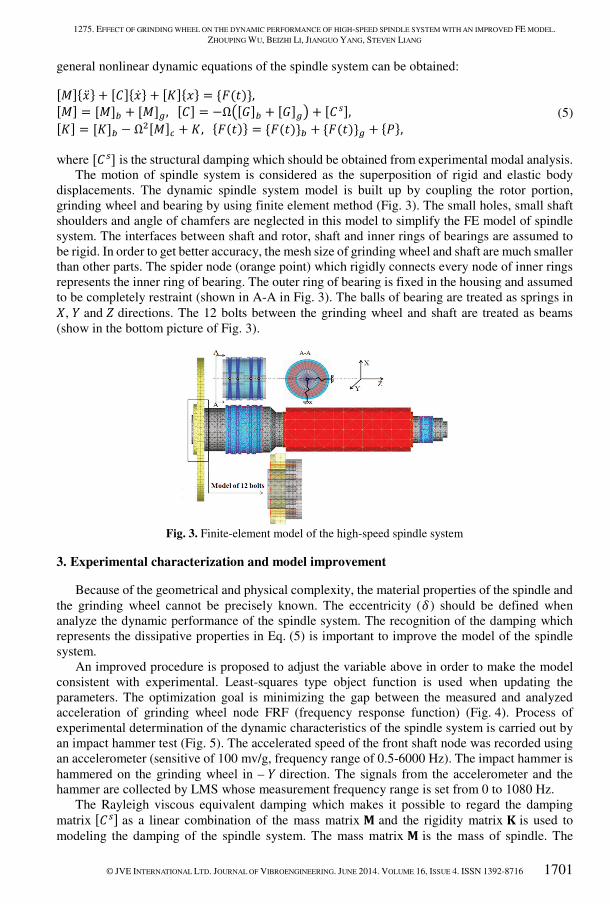
grinding wheel and bearing by using finite element method (Fig. 3). The small holes, small shaft
shoulders and angle of chamfers are neglected in this model to simplify the FE model of spindle
system. The interfaces between shaft and rotor, shaft and inner rings of bearings are assumed to
be rigid. In order to get better accuracy, the mesh size of grinding wheel and shaft are much smaller
than other parts. The spider node (orange point) which rigidly connects every node of inner rings
represents the inner ring of bearing. The outer ring of bearing is fixed in the housing and assumed
to be completely restraint (shown in A-A in Fig. 3). The balls of bearing are treated as springs in
@, A and B directions. The 12 bolts between the grinding wheel and shaft are treated as beams
(show in the bottom picture of Fig. 3).
Fig. 3. Finite-element model of the high-speed spindle system
3. Experimental characterization and model improvement
Because of the geometrical and physical complexity, the material properties of the spindle and
the grinding wheel cannot be precisely known. The eccentricity (�) should be defined when
analyze the dynamic performance of the spindle system. The recognition of the damping which
represents the dissipative properties in Eq. (5) is important to improve the model of the spindle
system.
An improved procedure is proposed to adjust the variable above in order to make the model
consistent with experimental. Least-squares type object function is used when updating the
parameters. The optimization goal is minimizing the gap between the measured and analyzed
acceleration of grinding wheel node FRF (frequency response function) (Fig. 4). Process of
experimental determination of the dynamic characteristics of the spindle system is carried out by
an impact hammer test (Fig. 5). The accelerated speed of the front shaft node was recorded using
an accelerometer (sensitive of 100 mv/g, frequency range of 0.5-6000 Hz). The impact hammer is
hammered on the grinding wheel in – A direction. The signals from the accelerometer and the
hammer are collected by LMS whose measurement frequency range is set from 0 to 1080 Hz.
The Rayleigh viscous equivalent damping which makes it possible to regard the damping
matrix �<?� as a linear combination of the mass matrix C and the rigidity matrix ; is used to
modeling the damping of the spindle system. The mass matrix C is the mass of spindle. The

1275. EFFECT OF GRINDING WHEEL ON THE DYNAMIC PERFORMANCE OF HIGH-SPEED SPINDLE SYSTEM WITH AN IMPROVED FE MODEL.
ZHOUPING WU, BEIZHI LI, JIANGUO YANG, STEVEN LIANG
1702 © JVE INTERNATIONAL LTD. JOURNAL OF VIBROENGINEERING. JUNE 2014. VOLUME 16, ISSUE 4. ISSN 1392-8716
rigidity matrix ; contains the spindle rigidity matrix ; of spindle and the rolling bearing rigidity
matrix ; of bearing.
Fig. 4. Procedure of numeric model update
Fig. 5. Experimental set up
Initial and updated value of the parameters above is show in Table 1. For the rotor portion, the
updated D is larger and E is smaller because the numeric model is simplified by ignoring holes,
small shoulder.
Table 1. Initial and updated parameters of spindle system
Parameters D (kg/m3� E (Pa) � (μm) F G �
Initial Value Shaft 7850 2.11E1011
0.4 0.5 0.2 0.2 Grinding Wheel 7850 2.11E1011
Updated Value Shaft 8023 1.97E1011
1 0.673 0.109 0.073 Grinding Wheel 7802 2.02E1011
Fig. 6. Experimental, initial and updated FRF of front shaft node

1275. EFFECT OF GRINDING WHEEL ON THE DYNAMIC PERFORMANCE OF HIGH-SPEED SPINDLE SYSTEM WITH AN IMPROVED FE MODEL.
ZHOUPING WU, BEIZHI LI, JIANGUO YANG, STEVEN LIANG
© JVE INTERNATIONAL LTD. JOURNAL OF VIBROENGINEERING. JUNE 2014. VOLUME 16, ISSUE 4. ISSN 1392-8716 1703
For the grinding wheel, the updated D and E are both smaller because the material of whole
part of grinding wheel is regarded as steel in initial model. The initial � is eccentricity without
grinding wheel from direction of spindle. The improved � is measured by SBS. The initial value
of F, G, � are defined by experience and improved by LMS. The front shaft node FRF from the
numeric model and experiment are show in Fig. 6. The improved analysis result generates a good
correspondence in a bandwidth of 200-900 Hz. The maximum error of the improved model is
about 5 %, while it is about 15 % for the initial model.
4. Dynamic analysis
Based on the updated model above, the FEMAP with Nastran is used to analyze the dynamic
performance of the High-speed grinding motorized spindle system. The parameters of the
high-speed motorized spindle are listed in Table 2.
Table 2. Parameters of the spindle system
Length of the spindle 715 mm
Front bearing HCB71924
Axial preload of front bearing 212 N
Rear bearing HCB71913
Axial preload of rear bearing 55 N
Diameter of the grinding wheel 400 mm
Maximum rotating speed of the spindle 10000 rpm
4.1. Dynamic performance analysis
For a rotor system, when the system rotates at the speeds equal to its synchronous whirl
frequencies, it will resonate due to the amount of residual unbalance which could not be avoided
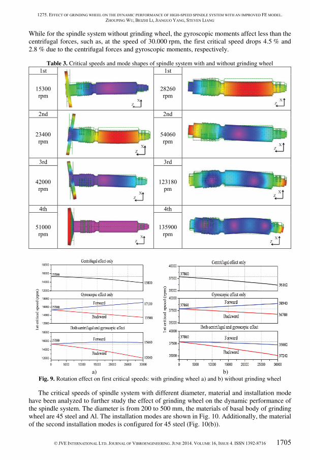
in manufacturing and assembling; these speeds are defined as critical speeds. In this study, the
first four critical speeds are 15300, 23400, 42000 and 51000 rpm, respectively; and corresponding
mode shapes are given in Table 3. It is shown in Table 3 that the first mode shape is located at the
front of shaft and grinding wheel, which will greatly affect the accuracy of machining; the second
is mainly the twisted mode of the grinding wheel around A axis and bending mode of the rotor;
the third is twisted mode of the grinding wheel around @ axis; and the fourth is the bending mode
of the grinding wheel. So the grinding wheel is a sensitive part to impact the dynamic behavior of
the spindle system.
The simulated dynamic stiffness from the FE model at the front shaft node of different
rotational speeds is shown in Fig. 7. It shows that the dynamic stiffness of the spindle system
decreases with the increase of rotation speed because of the rise of centrifugal force and
gyroscopic moment. When the spindle rotates at the maximum working speed (10000 rpm), the
dynamic stiffness is about 93 % of the static stiffness.
Fig. 7. Simulated dynamic stiffness at the spindle nose

1275. EFFECT OF GRINDING WHEEL ON THE DYNAMIC PERFORMANCE OF HIGH-SPEED SPINDLE SYSTEM WITH AN IMPROVED FE MODEL.
ZHOUPING WU, BEIZHI LI, JIANGUO YANG, STEVEN LIANG
1704 © JVE INTERNATIONAL LTD. JOURNAL OF VIBROENGINEERING. JUNE 2014. VOLUME 16, ISSUE 4. ISSN 1392-8716
Fig. 8 shows an impact force which is applied on the front shaft node in the radial direction.
The impact force which is 100 N changes as sine function and lasts 0.005 s (shown in Fig. 8(a)).
The radial displacement time response histories of the different parts of spindle system are shown
in Fig. 8(b). The grinding wheel node has the largest amplitude which is 8.5×10⁻⁷ m. After
0.0225 s, the amplitude decreases to less than 0.5×10⁻⁷ m. The amplitude of middle shaft node is
2×10⁻⁷ m and reduces to less than 0.5×10⁻⁷ m after 0.0113 s. The rear shaft node has the smallest
amplitude which is 0.7×10⁻⁷ m, and the amplitude only needs 0.0075 s to reach less than
0.5×10⁻⁷ m. From the analysis above it can be seen that the grinding wheel is the most sensitive
part of the high-speed spindle system for impact force.
a)
b)
Fig. 8. Impact response in the radial direction at different part of the spindle system:
200 Hz sine function a) and b) radial displacement time response histories
4.2. Comparison and discussion
To obtain the effect of grinding wheel on the dynamic performance of the spindle system, a
comparative study has been done between the spindle system with and without grinding wheel.
The first four critical speeds and their corresponding mode shapes of spindle system with and
without grinding wheel are listed in Table 3. It can be seen that the first critical speed of spindle
system without grinding wheel is 28260 rpm. It is much higher than the critical speed of spindle
system with grinding wheel, which is only 15300 rpm. The second to fourth critical speeds of
spindle system without grinding wheel is 54060, 123180 and 135900 rpm, respectively. These
critical speeds are also much higher than the corresponding speeds of spindle system with grinding
wheel.
The first mode shape of the spindle system without grinding wheel is mainly located at the
rotor which is in the middle of the spindle system. Compared with the spindle system with grinding
wheel, this model shape will not affect the accuracy of machining directly. The second mode shape
is the bending mode of the shaft in the front of the spindle system. The third is the bending mode
of both the front and rear part of the shaft and the fourth is the bending mode for the front, rear
and middle part of the shaft. These critical speeds and mode shapes are quite different to the
spindle system with grinding wheel. In summary, the grinding wheel has great influence on the
critical speeds and mode shapes.
In order to check the influence of centrifugal force and the gyroscopic moment of the spindle
system on critical speeds, a comparative analysis has be done between the spindle system with
and without grinding wheel. Fig. 9 shows the rotation effects from the spindle system with and
without grinding wheel on critical speeds. Both the centrifugal forces and gyroscopic moments
have a greater influence on the first critical speed of the spindle system with grinding wheel than
without grinding wheel. For the spindle system with grinding wheel, the gyroscopic moments
affect more than the centrifugal forces, for example, at the speed of 30.000 rpm, the first critical
speed drops 9.8 % and 11.8 % due to the centrifugal forces and gyroscopic moments, respectively.
1275. EFFECT OF GRINDING WHEEL ON THE DYNAMIC PERFORMANCE OF HIGH-SPEED SPINDLE SYSTEM WITH AN IMPROVED FE MODEL.
ZHOUPING WU, BEIZHI LI, JIANGUO YANG, STEVEN LIANG
© JVE INTERNATIONAL LTD. JOURNAL OF VIBROENGINEERING. JUNE 2014. VOLUME 16, ISSUE 4. ISSN 1392-8716 1705
While for the spindle system without grinding wheel, the gyroscopic moments affect less than the
centrifugal forces, such as, at the speed of 30.000 rpm, the first critical speed drops 4.5 % and
2.8 % due to the centrifugal forces and gyroscopic moments, respectively.
Table 3. Critical speeds and mode shapes of spindle system with and without grinding wheel
1st
1st
15300
rpm
28260
rpm
2nd
2nd
23400
rpm
54060
rpm
3rd
3rd
42000
rpm
123180
pm
4th
4th
51000
rpm
135900
rpm
a)
b)
Fig. 9. Rotation effect on first critical speeds: with grinding wheel a) and b) without grinding wheel
The critical speeds of spindle system with different diameter, material and installation mode
have been analyzed to further study the effect of grinding wheel on the dynamic performance of
the spindle system. The diameter is from 200 to 500 mm, the materials of basal body of grinding
wheel are 45 steel and Al. The installation modes are shown in Fig. 10. Additionally, the material
of the second installation modes is configured for 45 steel (Fig. 10(b)).

1275. EFFECT OF GRINDING WHEEL ON THE DYNAMIC PERFORMANCE OF HIGH-SPEED SPINDLE SYSTEM WITH AN IMPROVED FE MODEL.
ZHOUPING WU, BEIZHI LI, JIANGUO YANG, STEVEN LIANG
1706 © JVE INTERNATIONAL LTD. JOURNAL OF VIBROENGINEERING. JUNE 2014. VOLUME 16, ISSUE 4. ISSN 1392-8716
a)
b)
Fig. 10. Different installation modes of grinding wheel: without flange a) and b) with flange
Fig. 11 shows the first four critical speeds of the spindle system with different diameter,
material and installation modes of the grinding wheel. The horizontal axis is the diameter of the
grinding wheel. The vertical axis is the critical speeds of the spindle system. The black line stands
for the critical speed of spindle system with steel basal body grinding wheel. The red line expresses
the critical speed of spindle system with Al basal body grinding wheel. The blue line is the critical
speed of spindle system with the second installation mode. For the 1st critical speed (Fig. 11(a)),
all the three lines decrease as the diameters of the grinding wheel increase. The black and red line
fall slowly within 375 mm and go down quickly without 375 mm. Besides, the red line is always
above the black line. The blue line falls down sharply between 275 mm and 450 mm.
a)
b)
c)
d)
Fig. 11. First four critical speeds of the spindle system: a) 1st critical speed, b) 2nd critical speed, c) 3rd
critical speed and d) 4th critical speed

1275. EFFECT OF GRINDING WHEEL ON THE DYNAMIC PERFORMANCE OF HIGH-SPEED SPINDLE SYSTEM WITH AN IMPROVED FE MODEL.
ZHOUPING WU, BEIZHI LI, JIANGUO YANG, STEVEN LIANG
© JVE INTERNATIONAL LTD. JOURNAL OF VIBROENGINEERING. JUNE 2014. VOLUME 16, ISSUE 4. ISSN 1392-8716 1707
For the 2nd, 3rd and 4th critical speeds, the decrease of red lines are accordant with the 1st
critical speed. The black line in Fig. 11(b) falls down quickly within 300 mm and beyond 400 mm,
while between 300 mm and 400 mm it falls smoothly. The black lines in Fig. 11(c) and Fig. 11(d)
have the same trend as the Fig. 11(a). The changing trend of the two blue lines in Fig. 11(b) and
Fig. 11(a) are accordant. The blue lines in Fig. 11(c) and Fig. 11(d) are also nearly the same.
In summary, these four critical speeds of spindle system decrease as the increase of the
diameters of the grinding wheel. The four critical speeds of the spindle system with Al basal body
grinding wheel is always higher than the spindle system with steel basal body grinding wheel. For
the second installation mode of grinding wheel, the dynamic performance is better than the first
installation mode in some range, because the effect from flange changes as the diameters of
grinding wheel increase. When the diameter is small, the mode shape is mainly located at the
middle of shaft. The installation of flange increases the stiffness of the spindle system. So the
second installation has better dynamic performance in this case. While as the diameter rises up,
the mode shape transfers to the grinding wheel. The dynamic performance of the spindle system
without flange is better because of the larger stiffness of the connection. When the grinding wheel
is larger than 500 mm, it will be very flexible. In this situation, the flange will increase the stiffness
because of larger connect surface. For this spindle system whose grinding wheel fitted on the shaft
directly without flange, its dynamic performance is better when the diameter of grinding wheel is
400 mm.
5. Conclusion
In this paper, an integrated finite element model (FEM) of high-speed motorized spindle
system which contains the grinding wheel is developed. The FEM is verified and updated
experimentally to characterize the dynamic behavior of the spindle system. With the updated
model, the dynamic performance of spindle system and the effect of grinding wheel on the
dynamic performance of spindle system are analyzed. The results showed that:
1. The dynamic stiffness of the spindle system decreases as the rotation speed increases
because of the centrifugal force and gyroscopic moment. The grinding wheel node is the most
sensitive part to the exciting force.
2. The grinding wheel has a great effect on the critical speeds and their corresponding mode
shapes of the spindle system. The grinding wheel should be taken in to account when analyzing
the critical speeds and their corresponding mode shapes of the high-speed spindle system.
3. The spindle system with grinding wheel has larger centrifugal force and gyroscopic moment
than without grinding wheel. For the spindle system with grinding wheel, the gyroscopic moments
affect more than the centrifugal forces. For the spindle system with grinding wheel, it is opposite.
4. The spindle system with Al basal body grinding wheel has higher critical speed than the
spindle system with steel basal body grinding wheel when the diameter of grinding wheel is same.
In the diameter range of 300 mm to 400 mm, the installation mode without the flange has better
performance.
Acknowledgement
This paper is supported by Major National Science and Technology Project
(2011ZX04016-041-DH01).
References
[1] Zhouping Wu, Beizhi Li, Jianguo Yang, Xia Sheng A thermodynamics coupled modeling approach
for analysis and improvement of high-speed motorized spindle system. Journal of Vibroengineering,
Vol. 15, Issue 3, 2013.

1275. EFFECT OF GRINDING WHEEL ON THE DYNAMIC PERFORMANCE OF HIGH-SPEED SPINDLE SYSTEM WITH AN IMPROVED FE MODEL.
ZHOUPING WU, BEIZHI LI, JIANGUO YANG, STEVEN LIANG
1708 © JVE INTERNATIONAL LTD. JOURNAL OF VIBROENGINEERING. JUNE 2014. VOLUME 16, ISSUE 4. ISSN 1392-8716
[2] Harkany The determination of the optimum bearing distance with regard to bearing stiffness in the
case of shafts with constant and variable cross sections, respectively. Machine Tool Industry Research
Association Translation, Vol. 33, 1961, p. 103-117.
[3] Opitz H., Gunther D., Kalkert W., Kunkel H. The study of the deflection of rolling bearing for
machine tool spindles. Proceeding of the 6th MTDR Conference, Vol. 34, 1965, p. 257-269.
[4] Vincent Gagnol, Thien-PhuLe, Pascal Ray Modal identification of spindle-tool unit in high-speed
machining. Mechanical Systems and Signal Processing, Vol. 25, 2011, p. 2388-2398.
[5] Ruhl R. L., Booker J. F. A finite element model for distributed parameter turbo rotor systems. ASME
Journal of Engineering for Industry, 1972, p. 128-139.
[6] Nelson H. D. A finite rotating shaft element using Timoshenko beam theory. ASME Journal of
Mechanical Design, Vol. 102, Issue 4, 1980, p. 793-803.
[7] Chen C. H., Wang K. W., Shin Y. C. An integrated approach toward the dynamic analysis of
high-speed spindles, Part I: system model; Part II: dynamics under moving end load. International
Journal of Vibration and Acoustics, Vol. 116, Issue 4, 1994, p. 506-522.
[8] Gagnol V., Bouzgarroua B. C., Raya P., Barra C. Model-based chatter stability prediction for
high-speed spindles. International Journal of Machine Tools and Manufacture, Vol. 47, 2007,
p. 1176-1186.
[9] Hongrui Cao, BingLi, Zhengjia He Chatter stability of milling with speed-varying dynamics of
spindles. International Journal of Machine Tools and Manufacture, Vol. 52, 2012, p. 50-58.
[10] Sun-Min Kim, Jae-Hoon Ha, Sung-Ho Jeong, Sun-Kyu Lee Effect of joint conditions on the
dynamic behavior of a grinding wheel spindle. International Journal of Machine Tools and
Manufacture, Vol. 41, 2001, p. 1749-1761.
[11] Yuzhong Cao, Yusuf Altintas A general method for the modeling of spindle-bearing systems. Journal
of Mechanical Design, 2004, p. 26-134.
[12] Shuyun Jiang, ShufeiZheng A modeling approach for analysis and improvement of spindle-drawbar-
bearing assembly dynamics. International Journal of Machine Tools and Manufacture, Vol. 50, 2010,
p. 131-142.
[13] Yuzhong Cao, Altintas Y. Modeling of spindle-bearing and machine tool systems for virtual
simulation of milling operations. International Journal of Machine Tools and Manufacture, Vol. 47,
2007, p. 1342-1350.
[14] Forestier F., Gagnol V., Ray P., Paris H. Model-based operating recommendations for high-speed
spindles equipped with a self-vibratory drilling head. Mechanism and Machine Theory, Vol. 46, 2011,
p. 1610-1622.
[15] Jones A. B. A general theory for elastically constrained ball and radial roller bearings under arbitrary
load and speed conditions. ASME J. Basic Eng., p. 309-320.