
1270 IEEE TRANSACTIONS ON SMART GRID, VOL. 5,...
12
1270 IEEE TRANSACTIONS ON SMART GRID, VOL. 5, NO. 3, MAY 2014 Coordinated V-f and P-Q Control of Solar Photovoltaic Generators With MPPT and Battery Storage in Microgrids Sarina Adhikari, Student Member, IEEE, and Fangxing Li, Senior Member, IEEE Abstract—The microgrid concept allows small distributed en- ergy resources (DERs) to act in a coordinated manner to provide a necessary amount of active power and ancillary service when re- quired. This paper proposes an approach of coordinated and in- tegrated control of solar PV generators with the maximum power point tracking (MPPT) control and battery storage control to pro- vide voltage and frequency (V-f) support to an islanded microgrid. Also, active and nonactive/reactive power (P-Q) control with solar PV, MPPT and battery storage is proposed for the grid connected mode. The control strategies show effective coordination between inverter V-f (or P-Q) control, MPPT control, and energy storage charging and discharging control. The paper also shows an effec- tive coordination among participating microresources while con- sidering the case of changing irradiance and battery state of charge (SOC) constraint. The simulation studies are carried out with the IEEE 13-bus feeder test system in grid connected and islanded mi- crogrid modes. The results clearly verify the effectiveness of pro- posed control methods. The simulations are carried out in Matlab and Simpowersystems. Index Terms—Active and reactive power control, distributed energy resource (DER), distributed generation (DG), maximum power point tracking (MPPT), voltage and frequency control, solar photovoltaic (PV). I. NOMENCLATURE Instantaneous PCC voltage Average PCC voltage Instantaneous inverter output voltage Average inverter output voltage Coupling inductor Inverter average active power Inverter average reactive power Inverter average apparent power Manuscript received December 22, 2012; revised June 10, 2013, October 07, 2013; accepted January 02, 2014. Date of publication February 28, 2014; date of current version April 17, 2014. This work was supported in part by Oak Ridge National Laboratory. This work also made use of the Shared Facilities and was supported by the Industry Partnership Program of CURENT, an Engineering Research Center (ERC) Program of the U.S. National Science Foundation and Department of Energy. Paper no. TSG-00880-2012. The authors are with the Department of Electrical Engineering and Com- puter Science, The University of Tennessee, Knoxville, TN 37996 USA (e-mail: fl[email protected]). Digital Object Identifier 10.1109/TSG.2014.2301157 Duty cycle of DC/DC booster Reference maximum power PV active power output Phase shift between and Reference microgrid frequency Measured microgrid frequency AC side total average active power DC side average active power Reference battery active power Actual injected battery active power Average reactive power reference (Reactive load) Actual generated reactive power Average active power reference (Active load) Actual generated active power II. INTRODUCTION T HE microgrid is a collection of distributed generators or microresources, energy storage devices, and loads which operate as a single and independent controllable system capable of providing both power and heat to the area of service [1]. The microresources that are incorporated in a microgrid are com- prised of small units, less than 100 kW, provided with power electronics (PE) interface. Most common resources are Solar Photovoltaic (PV), Fuel Cell (FC), or microturbines connected at the distribution voltage level. In a microgrid, the microsources and storage devices are con- nected to the feeders through the microsource controllers (MCs) and the coordination among the microsources is carried out by the central controller (CC) [2]. The microgrid is connected to the medium voltage level utility grid at the point of common coupling (PCC) through the circuit breakers. When a microgrid is connected to the grid, the operational control of voltage and frequency is done entirely by the grid; however, a microgrid still supplies the critical loads at PCC, thus, acting as a PQ bus. In islanded condition, a microgrid has to operate on its own, inde- pendent of the grid, to control the voltage and frequency of the microgrid and hence, acts like a PV (power-voltage) bus. The 1949-3053 © 2014 IEEE. Personal use is permitted, but republication/redistribution requires IEEE permission. See http://www.ieee.org/publications_standards/publications/rights/index.html for more information.
Transcript of 1270 IEEE TRANSACTIONS ON SMART GRID, VOL. 5,...

1270 IEEE TRANSACTIONS ON SMART GRID, VOL. 5, NO. 3, MAY 2014
Coordinated V-f and P-Q Control of SolarPhotovoltaic Generators With MPPT and Battery
Storage in MicrogridsSarina Adhikari, Student Member, IEEE, and Fangxing Li, Senior Member, IEEE
Abstract—The microgrid concept allows small distributed en-ergy resources (DERs) to act in a coordinated manner to providea necessary amount of active power and ancillary service when re-quired. This paper proposes an approach of coordinated and in-tegrated control of solar PV generators with the maximum powerpoint tracking (MPPT) control and battery storage control to pro-vide voltage and frequency (V-f) support to an islanded microgrid.Also, active and nonactive/reactive power (P-Q) control with solarPV, MPPT and battery storage is proposed for the grid connectedmode. The control strategies show effective coordination betweeninverter V-f (or P-Q) control, MPPT control, and energy storagecharging and discharging control. The paper also shows an effec-tive coordination among participating microresources while con-sidering the case of changing irradiance and battery state of charge(SOC) constraint. The simulation studies are carried out with theIEEE 13-bus feeder test system in grid connected and islanded mi-crogrid modes. The results clearly verify the effectiveness of pro-posed control methods. The simulations are carried out in Matlaband Simpowersystems.
Index Terms—Active and reactive power control, distributedenergy resource (DER), distributed generation (DG), maximumpower point tracking (MPPT), voltage and frequency control,solar photovoltaic (PV).
I. NOMENCLATURE
Instantaneous PCC voltage
Average PCC voltage
Instantaneous inverter output voltage
Average inverter output voltage
Coupling inductor
Inverter average active power
Inverter average reactive power
Inverter average apparent power
Manuscript received December 22, 2012; revised June 10, 2013, October 07,2013; accepted January 02, 2014. Date of publication February 28, 2014; date ofcurrent version April 17, 2014. This work was supported in part by Oak RidgeNational Laboratory. This work also made use of the Shared Facilities and wassupported by the Industry Partnership Program of CURENT, an EngineeringResearch Center (ERC) Program of the U.S. National Science Foundation andDepartment of Energy. Paper no. TSG-00880-2012.The authors are with the Department of Electrical Engineering and Com-
puter Science, The University of Tennessee, Knoxville, TN 37996 USA (e-mail:[email protected]).Digital Object Identifier 10.1109/TSG.2014.2301157
Duty cycle of DC/DC booster
Reference maximum power
PV active power output
Phase shift between and
Reference microgrid frequency
Measured microgrid frequency
AC side total average active power
DC side average active power
Reference battery active power
Actual injected battery active power
Average reactive power reference (Reactiveload)
Actual generated reactive power
Average active power reference (Activeload)
Actual generated active power
II. INTRODUCTION
T HE microgrid is a collection of distributed generators ormicroresources, energy storage devices, and loads which
operate as a single and independent controllable system capableof providing both power and heat to the area of service [1]. Themicroresources that are incorporated in a microgrid are com-prised of small units, less than 100 kW, provided with powerelectronics (PE) interface. Most common resources are SolarPhotovoltaic (PV), Fuel Cell (FC), or microturbines connectedat the distribution voltage level.In a microgrid, the microsources and storage devices are con-
nected to the feeders through the microsource controllers (MCs)and the coordination among the microsources is carried out bythe central controller (CC) [2]. The microgrid is connected tothe medium voltage level utility grid at the point of commoncoupling (PCC) through the circuit breakers. When a microgridis connected to the grid, the operational control of voltage andfrequency is done entirely by the grid; however, a microgrid stillsupplies the critical loads at PCC, thus, acting as a PQ bus. Inislanded condition, a microgrid has to operate on its own, inde-pendent of the grid, to control the voltage and frequency of themicrogrid and hence, acts like a PV (power-voltage) bus. The
1949-3053 © 2014 IEEE. Personal use is permitted, but republication/redistribution requires IEEE permission.See http://www.ieee.org/publications_standards/publications/rights/index.html for more information.

ADHIKARI AND LI: COORDINATED V-F AND P-Q CONTROL 1271
operation and management in both the modes is controlled andcoordinated with the help of microsource controllers (MCs) atthe local level and central controller (CCs) at the global level.Similar to the traditional synchronous generator frequency
control [3], the microgrid voltage and frequency control can alsobe performed using droop control methods [4]–[8]. The presentwork provides fast response characteristics for voltage and fre-quency control as compared to the secondary control consid-ered in [8]. The analogy between inverter control and the syn-chronous generator control in an islanded microgrid is studiedin detail in [9]. In the islanded mode, there is the necessity ofhaving a reference voltage and frequency signals in the micro-grid inverter control [10].The operation and control of the inverter interface of re-
newable-based distributed energy resources (DERs), like SolarPhotovoltaic (PV) in a microgrid, is a real challenge, especiallywhen it comes to maintaining both microgrid voltage and fre-quency within an acceptable range. A voltage control methodbased on traditional droop control for voltage sag mitigationalong with voltage ride through capability is proposed in [11].A dynamic voltage regulation based on adaptive control isproposed in [12], [13]. However, there are not many researchworks performed on V-f or P-Q control using solar PV in-cluding MPPT control and battery storage in microgrids. In[14], frequency regulation with PV in microgrids is studied;however, this work does not consider the voltage controlobjective and lacks battery storage in the microgrid.In [15], a small scale PV is considered in a grid-connected
mode to control the active and reactive power of the system.Here, the control methods consider abc-dq0 transformation andvice versa which is avoided in the present paper. In [16], powermodulation of solar PV generators with an electric double layercapacitor as energy storage is considered for frequency control.In [17], load frequency control is implemented inmicrogrid withPV and storage; however, this work also lacks the considerationof a voltage control objective. The voltage and frequency con-trol with solar PV and battery in microgrid with an inductionmachine is investigated in [18]; however, this work does not ex-plain the transfer mechanism of controls to consider the batterySOC constraint. In summary, the previous works in this topiceither lack the incorporation of an energy storage componentor the voltage control objective along with frequency controlor the incorporation of control transition in different scenarios.The present work fulfills these gaps by considering all of theseobjectives.This paper proposes several control algorithms through
which the capability of PV generators for voltage and fre-quency (V-f) control and active and nonactive/reactive power(P-Q) control in islanded and grid connected microgrids couldbe harnessed. Detailed models of PV, battery, inverter and con-verter are considered for the study. The major contribution andnovelty of the proposed control methods lie in the coordinationamong individual proposed control methods: MPPT controlat the PV side, battery control, and V-f/P-Q control algorithmat the inverter side. These three control algorithms at threestages are jointly linked through a power balance objectiveat the DC and AC side of the inverter so that the DC sidevoltage is indirectly controlled at the desired value in order
Fig. 1. One diode equivalent circuit of Solar PV.
to maintain the AC side voltage at the utility desired voltage.Also, the proposed control methods have the capability ofhandling battery state of charge (SOC) constraints through thecoordination of controls between participating microresourcesin the microgrid. This is a very important contribution from thiswork as compared to other literatures in this area. At the sametime, the controls can seamlessly transform from one modee.g., inverter P-Q control in grid connected mode to V-f controlin islanded mode. The proposed control methods are validatedwith satisfactory results. The controls are developed in abcreference frames using the RMS/average values of voltagesand active and reactive power. Hence, it is easy and efficientto implement, and avoids the transformation to and from otherreference frames which greatly simplifies the control strategies.The chosen control parameters in the proposed methodologiesare, however, dependent on the PV, battery, and external powergrid conditions. These parameters can be adaptively achievedwith the changing system conditions which could be a verypromising future direction of this work.The rest of the paper is organized as follows: Section III
briefly presents the analytical modeling of Solar PV with modelvalidation results. Section IV shows the PV system configu-ration, describes the modeling of the battery storage, and pro-vides information about the structure of IEEE 13-bus distribu-tion feeder under study. Section V describes the proposed coor-dinated V-f and P-Q control algorithms while incorporating PVMPPT control and battery storage control. Section VI presentsconvincing results to prove the effectiveness of the proposedcontrol algorithms. Finally, Section VII summarizes the majorcontributions of the paper.
III. SOLAR PV MODELING AND VALIDATION
The commonly accepted solar cell model is a one diodemodel[19]. This work uses the single diode model of the solar cell tomodel the Kyocera KC200GT solar array, which is shown inFig. 1.The I-V characteristics of a solar array, as shown in Fig. 2,
are represented by (1).
(1)
where and are the photo current and the diode satura-tion currents, respectively; is the thermalvoltage of the array, being the cells connected in se-ries for greater output voltage, is the Boltzmann constant( J/K), (Kelvin) is the temperature ofthe p-n junction of the diode, and ( C)is the electron charge; and are the equivalent seriesand shunt resistances of the array, respectively; and is the

1272 IEEE TRANSACTIONS ON SMART GRID, VOL. 5, NO. 3, MAY 2014
Fig. 2. The - characteristics of Kyocera KC200GT from simulation with (a) varying irradiance at a cell temperature of 25 C and; (b) varying cell temperatureat 1000W/m .
TABLE IPV PANEL PARAMETERS AT 1000 W/M AND 25 C
ideality factor usually chosen in the range . Hereis taken as 1.The photocurrent of the PV array depends linearly on the
solar irradiance and the cell temperature, as shown by (2) [19].
(2)
where is the photocurrent at the standard test condition(STC, 25 C and 1000 W/m is the short circuit current/temperature coefficient; is the dtifference between the ac-tual and nominal temperature in Kelvin; is the irradiation onthe device surface; and is the nominal radiation, both inW/m .
can be calculated based on (3)
(3)
Using these fundamental equations and parameters fromthe data sheet, the PV model is developed and verified withthe panel datasheet. The I-V characteristics of KC200GT fordifferent irradiance levels at the cell temperature of 25 C andvarying cell temperature for a constant irradiance level of 1000W/m as obtained from the simulation are shown in Figs. 2(a)and (b), respectively. The similarities of the I-V curves fordifferent conditions with the corresponding curves in theKC200GT panel datasheet prove the validity of the developedsolar panel model. The parameters of the PV panel under studyare shown in Table I.
The PV system under study for the proposed V-f and P-Qcontrol has 125 strings with each string having 4 series con-nected panels. The Maximum Power Point (MPP) for a singlepanel of KC200GT at 1000 W/m and 25 C (STC) is 200 W.Hence, the maximum power of the PV generator at STC is
kW. The MPP varies according to thechange in irradiance level and cell temperature.
IV. PV SYSTEM CONFIGURATION AND SYSTEM DESCRIPTION
A. PV System Configuration
Fig. 3 shows the PV system configuration for V-f and P-Qcontrol with PV operating at MPP including the battery storagebackup. It is a two-stage configuration where a DC-DC boostconverter is used for MPPT control. The system also considersa battery back-up in case of emergencies while maintaining thevoltage and frequency of the microgrid or while trying to supplythe critical loads.A battery is connected in parallel to the PV to inject or absorb
active power through a bidirectional DC-DC converter. Whenthe battery is absorbing power, the converter operates in thebuck mode and when battery is injecting power to the grid, itoperates in the boost mode. The operation mode is maintainedthrough the control signal provided to the converter switches.The PV system is connected to the grid through a coupling
inductor . The coupling inductor filters out the ripples in thePV output current. The connection point is called the point ofcommon coupling (PCC) and the PCC voltage is denoted as
. The rest of the system in Fig. 3 denotes the IEEE 13-busdistribution feeder which is simplified as a substation with thefeeder equivalent impedance, . The details of theIEEE-13 bus system will be described in the next section. ThePV source is connected to the DC link of the inverter with acapacitor . The PV is the active power source, and the ca-pacitor is the reactive power source of the PV system.According to the instantaneous power definitions, for a bal-
anced three-phase system, if and denote the instanta-neous PCC voltage and the inverter output voltage (harmonics

ADHIKARI AND LI: COORDINATED V-F AND P-Q CONTROL 1273
Fig. 3. System configuration of V-f control with solar PV generator operatingat MPPT with a battery storage system.
neglected), respectively, then the average power of the PV de-noted as , the apparent power and the average reactivepower of the PV are as given below [20]
(4)
(5)
(6)
Here, is the phase angle of relative to the PCC voltage.and in (4) and (6) can be approximated by the first
terms of the Taylor series if the angle is small, as shown in (7)and (8):
(7)
(8)
B. Battery Modeling
In this paper, the battery model is taken from the MATLABSimPowerSystems library with appropriate parameters whichwill be used for the proposed V-f and P-Q controls. The detaileddescription about the battery model is given in [21]. Due to the
intermittent and uncertain nature of solar power output and alsothe highly fluctuating load demands, deep cycle lead acid bat-teries are the most common type of battery storage in micro-grid applications because the maximum capacity of the batterycan be utilized. Hence, in this paper, a battery is modeled as alead acid battery with appropriate choice of parameters for deepcycle application. It is assumed that the lead acid battery can bedischarged up to SOC of 20% and can be charged up to SOC of80%.The battery model in [21] is an analytical model with two
equations representing the battery discharge and charge models.The battery discharge and charge model for a lead acid batteryis given by (9) and (10), respectively
(9)
(10)
where is the battery voltage (V), is the battery constantvoltage (V), is polarisation constant (V/Ah) or polarisationresistance is battery capacity (Ah),battery charge (Ah), is exponential zone amplitude (V),is exponential zone time constant inverse (Ah ), is the in-ternal resistance is battery current (A), and is filteredcurrent (A).In this model, the term for polarisation voltage and polarisa-
tion resistance is considered to model the Open Circuit Voltage(OCV) of the battery more accurately. The term inside the firstsquare bracket in (10) represents the polarisation resistance andthe second square bracket represents the polarisation voltage.The size of the battery is selected to provide a maximum
backup power to compensate for the PV generation in the caseof a very small or no irradiance level. In this work, the MPP ofPV generator at STC is 100 kW. Hence, the battery is chosento provide this amount of power for a maximum of 1 hour withan energy content of 100 kWh. The battery backup is consid-ered for short duration applications like frequency control andsupplying power to critical loads in the event of emergency sit-uations. One hour of battery backup is considered to be enoughfor other backup generators to take over the controls in the mi-crogrid emergency situations.
C. Description of IEEE 13-Bus Distribution Feeder
The diagram of the IEEE 13-bus distribution test system isshown in Fig. 4. It consists of a substation, 13 buses or nodes,11 line sections, and 8 loads. The loads comprise of a combi-nation of constant impedance, constant current, and constantpower (ZIP) loads but most of them are constant power loads.The substation is at 115 kV and it is stepped down to 4.16 kV bya distribution transformer (T1). There is one more transformer(T2) which steps down 4.16 kV to 480 V.In the grid connected mode, the substation located at Bus 650
at 115 kV level is considered as a source. In an islanded micro-grid case, a diesel generator connected at the same bus suppliesthe microgrid with a fixed amount of active power as referencedby the central controller (CC) of the microgrid.

1274 IEEE TRANSACTIONS ON SMART GRID, VOL. 5, NO. 3, MAY 2014
Fig. 4. IEEE-13 bus distribution feeder.
Fig. 5. Integrated Solar PV MPPT and V-f control diagram.
V. MPPT AND BATTERY INTEGRATED V-F AND P-Q CONTROLMETHODS
A. MPPT and Battery Integrated V-f Control Method
The MPPT and battery integrated V-f control diagrams areshown in Figs. 5 and 6, respectively. The control comprisesof one loop for MPPT control, two different loops for V-fcontrol at the inverter side and another loop for battery powermanagement.
Fig. 6. Battery power control diagram.
The loop 1 in Fig. 5 is a MPPT control at the PV arrayside which uses the reference MPP, from the look uptable of irradiance versus MPP. Then, it compares the actualPV power output, with this reference and feeds this errorto a PI controller, which outputs the duty cycle forthe DC-DC booster so that the array always operates at thereferenced point. The equation for this control loop is givenby (11). Here, and are the controller proportional andintegral gains respectively
(11)
Another feedback PI controller is used for voltage controlat AC side. As shown in the control diagram in Fig. 5 (loop2), the PCC voltage is measured and the rms value of iscalculated. Then, the rms value is compared to a voltagereference which could be a voltage specified by the utility,and the error is fed to a PI controller. The inverter output voltage
is controlled so that it is in phase with the PCC voltage,and the magnitude of the inverter output voltage is controlledso that the PCC voltage is regulated at a given level . Thecontrol scheme can be specifically expressed as (12).
(12)
where and are the controller gains for this loop.In (12), 1 has been added to the right-hand side such that
when there is no injection from the PV generator, the PV outputvoltage is exactly the same as the terminal voltage.The frequency control is carried out by controlling the active
power output at the inverter side as shown in the outermost loop3. The referenced microgrid frequency of 60 Hz is comparedwith the measured value and this error is fed to the PI controller
that provides the phase shift contribution which shiftsthe voltage waveform in timescale such that the active power

ADHIKARI AND LI: COORDINATED V-F AND P-Q CONTROL 1275
injected will be enough to maintain the frequency at 60 Hz nom-inal value. The equation for this control is given by (13)
(13)
There is another controller used in the same loop 3. Thiscontroller maintains active power balance between the AC andDC sides of the inverter. The reference signal for is obtainedfrom the dynamically changing active power injection from theinverter at the AC side as determined by the output of . Themeasured AC side active power, is multiplied by afactor of 1.02 considering the efficiency of inverter as 98% suchthat the DC side active power is 102% of the AC side activepower. The DC side active power is compared with this valueof AC side power and the error is fed to to obtain the phaseshift contribution from this loop as . The equation for thiscontrol is given by (14)
(14)
The phase shift contributions from DC and AC sides, andare then averaged as given by (15) to obtain the final phase
shift, of the voltage waveform, which, then, generatesthe voltage reference signal for the inverter PWM
(15)
Here, the reason behind considering phase shift contributionsfrom both DC and AC side active power is to control the DCside voltage and achieve the desired value. By making andclose in range through the controller gains, it can be as-
sured that the active power at the DC and AC sides is balanced.This, coupled with the voltage control loop, assures that the DCside voltage is maintained at the value desired by the AC sidevoltage.The controls shown in the diagram of Fig. 5 and described
above are also integrated with the battery power control shownin Fig. 6. The battery is incorporated in the PV system config-uration in order to supply or absorb active power and supportthe frequency control objective with the PV generator. If thereis abundant solar power and the active power required for fre-quency control is less than PV MPP, then the battery will becharged. If there is not enough solar power available and if theactive power required for frequency control is more than PVMPP, then the battery will supply the deficit power in order tomaintain the microgrid frequency at 60 Hz. Hence, the controlmethod for the battery charge/discharge that depends on this re-quirement is developed as shown in Fig. 6. It also shows theselection of charge and discharge modes which handle the bat-tery SOC constraint and will be described later in the Part B ofthis section.In Fig. 6, the reference power to the battery, is gen-
erated dynamically by subtracting the inverter active power in-jection, from the power generated by . Thecontroller comprised of a PI controller, which receives theerror signal obtained after subtracting the actual battery power,
from the battery reference, . The signal obtained
from is then compared with a triangular waveform of unitymagnitude to generate the signal, . This is similar to commonPulse Width Modulation (PWM) in inverter controls. and
are the proportional and integral gains respectively. Theequation for this control is given by (16)
(16)One more step is considered to differentiate the charging and
discharging mode of the battery. This is undertaken by com-paring with . If , the battery isin charging mode, hence, the signal obtained from the PWM,and the result of this comparison is passed through a log-
ical AND to generate a switching signal which activates theBuck mode of the DC-DC converter. If the condition
is false, (i.e., ), the opposite of thissignal and is passed through a logical AND to generate aswitching signal which activates the Boost mode of the DC-DCconverter. Hence, with this control logic, the converter is ca-pable of operating in both directions and therefore, effectivelycharging and discharging the battery whenever required. Thiswill be verified through the results presented in Section VI ofthis paper.
B. Modification of V-F Control With Battery SOC Constraint
When there is abundant solar irradiance available and theactive power required for the microgrid frequency control isless than active power produced by the PV generator at MPPi.e., and at the same time the batterySOC is 80%, then, the battery cannot be charged beyond thisupper limit of SOC. In such case, decreasing the output powerof PV generator would lead to underutilization of the solar re-source. Hence, a global control mechanism is required in a mi-crogrid which can transition the PV control from frequency con-trol mode to constant power mode with power to be generatedat . Meanwhile, there should be a mechanism to allowany other generator of the microgrid to handle the frequencycontrol problem. In the microgrid system under consideration,there is a diesel generator which can decrease its generation inorder to match the PV generation increase. Hence, the powerbalance of the system will be maintained in order to control themicrogrid frequency.Similarly, when the irradiance is low such that the maximum
power from PV generator is not enough to maintain the micro-grid frequency i.e., and at the same time,the battery SOC is 20%, then the battery will not be able to backup the PV generator. In such case, the frequency control func-tion needs to be transferred to other available generator if pos-sible, in this case, a diesel generator. Again, a global controlmechanism becomes an absolute necessity for allowing the tran-sition of PV generator control from frequency control mode toconstant MPP mode and the diesel generator control from con-stant active power mode to frequency control mode such thatthe frequency stability of the microgrid can be achieved.Figs. 6, 7, and 8 show the modifications of controls at dif-
ferent stages in the microgrid in order to handle the above situa-tions. Fig. 7 shows the transition of the diesel generator controlfrom constant active power control to frequency control. Insteadof considering the error between the reference electrical power

1276 IEEE TRANSACTIONS ON SMART GRID, VOL. 5, NO. 3, MAY 2014
Fig. 7. Diesel generator control transition.
Fig. 8. Modification of PV inverter frequency control loop.
and the measured electrical power to generate the mechanicalpower reference, the frequency error is considered in the con-trols. Fig. 8 shows the modification in frequency control loopof the PV inverter which includes the transition to another con-stant active power control loop. During the simulation process,the transition time is heuristically selected as 8 sec so that thesmoothness in the transfer of controls can be observed.The slight modification required in the battery control for
taking care of the battery SOC is also shown in Fig. 6. It includesincorporation of a signal for selecting the charge or dischargemode of the battery. When the SOC % or SOC %, then,both the charge and dischargemode are given the value of 0 suchthat the output is always zero for these two cases. In other cases,the charge mode would take a value of 1 and the discharge modewould take a value of 0 if the battery is charging, and vice versaif the battery is discharging.With these modifications in the existing control structure,
the IEEE 13-bus system acting as a microgrid can handlethe problem of under frequency and voltage during islandingthrough the proper coordination of the participating generatorseven without the battery. This can be observed from the resultsto be presented later in Section VI-B.
C. MPPT and Battery Integrated P-Q Control Method
This sub-section presents the proposed coordinated activeand nonactive/reactive (P-Q) power control integrated withPV MPPT and battery controls. Either in grid connected orislanded mode, the microresources may be required to supplycritical loads like hospitals, industries, etc. The proposed
Fig. 9. Integrated Solar PV MPPT and PQ control diagram.
control strategy is applicable particularly for such cases. TheMPPT control part for generating the duty cycle of a propercontrol for the DC-DC boost converter is the same as describedin Section V-A above and hence, will not be explained here.Thus, Fig. 9 shows the P-Q control blocks only, leaving behindthe MPPT control block which is also present in the entireintegrated control system. The P-Q control initially proposedin [22] and implemented in a larger system in [23] is convertedto a more robust control with the integration of MPPT controland battery storage control in the present work.The inverter side P-Q control is slightly modified version of
inverter V-f control. It is entirely based on the relationship of ac-tive and reactive power at PCC with inverter output phase andvoltage magnitude as given by the (7) and (8), respectively. InFig. 9 (loop 2), the measured reactive power injection at PCCis compared with the referenced reactive load and this errorsignal is passed to the PI controller, . Then, the term ob-tained is multiplied by the terminal voltage to obtain the ref-erence voltage which is in phase with . The control loop3 in Fig. 9 handles active power control through the controller,
to generate the phase shift contribution and at the sametime insure the active power balance between AC and DC sidesthrough the controller, . This is already explained in detail inSection V-A for V-f control. Thus, the equations for P-Q controlare given by (17)–(20)
(17)
(18)
(19)
(20)
Equation (17) represents the reactive power control loop, (18)represents the active power control loop, and (19) ensures theactive power balance between the DC and AC sides of the in-verter. Equation (20) averages the phase shift contribution ob-tained from the active power control at the AC and DC sides

ADHIKARI AND LI: COORDINATED V-F AND P-Q CONTROL 1277
TABLE IICONTROLLER GAIN PARAMETERS FOR V-F CONTROL (CASE 1)
such that the active power control at AC side and power bal-ance objectives are taken into account.The battery control integrated into the P-Q control is the same
as the one described in the Section V-A.
VI. SIMULATION RESULTS AND DISCUSSIONS
This section presents the simulation results obtained with ap-plications of the proposed control methods to the IEEE 13-busdistribution feeder presented in Section IV-C. First, the resultsobtained from the coordinated V-f control are presented whichis followed by the results from the coordinated P-Q control. Ingrid connected mode, the distribution feeder is considered to besupplied by a central generator with a substation at Bus 650 at115 kV level and a PV generator at Bus 632. Hence, in an is-landed case, the distribution feeder is supplied by a diesel gen-erator and a PV connected at Buses 650 and 632, respectively.
A. Test of V-F Control in Microgrid Mode
For the demonstration of the V-f control algorithm,two different irradiance cases are considered: Case 1 with
W/m and Case 2 withW/m . The PI controller gain parameters for Case 1 are givenin Table II. The controller gains should be adjusted slightly forthe change in irradiance.While moving from the grid connected to microgrid mode,
the diesel generator is controlled to generate a fixed amount ofactive power according to the command from the central con-troller. The diesel generator produces a fixed amount of 1.25MW throughout the simulation period as shown in Fig. 10(a). Italso shows the reactive power generated from the diesel gener-ator.In the islandedmode, the active power generated by the diesel
generator is not enough to fulfill the power demand of themicro-grid. Fig. 10(b) shows the microgrid frequency which initiallydips to a value of 57.8 Hz due to the load-generation imbalance.The frequency control from the PV generator starts at 2.2 secwhich quickly regulates the frequency back to 60 Hz in 2 sec.Fig. 10(c) shows the plot of the PCC voltage in p.u. It can beobserved that voltage is also quickly regulated at 1 p.u. after thecontrol is started.Fig. 10(d) shows the active and reactive power injection from
the PV inverter which regulates the frequency and voltage of themicrogrid. The active power injection from the inverter, whichis required to maintain the frequency at 60 Hz in both cases,is around 80 kW. However, there is a difference in the share
Fig. 10. Results of coordinated V-f control with solar PV includingMPPT con-trol and battery control.
of the PV generator and the battery energy storage while pro-viding the required 80 kW to the microgrid. This is evident fromFig. 10(e) which shows the active power from the PV, the bat-tery, and the inverter, respectively, for both cases. In Case 1,solar irradiance is abundant at 1000 W/m and hence, the PVgenerates the maximum power of 100 kW which is more thanis required to maintain the microgrid frequency. The surplus 20kW is used to charge the battery. The negative sign in batterypower means that it is a charging phase, i.e., the battery absorbspower. In Case 2, PV generates only around 75 kW at MPP dueto decreased irradiance. This is not sufficient to maintain the mi-crogrid frequency at 60 Hz. Hence, the deficit power of around5 kW is supplied by the battery as shown by the 4th (PBatt Case2) curve in Fig. 10(e). Here, the positive sign of battery powermeans that it injects active power into the microgrid.

1278 IEEE TRANSACTIONS ON SMART GRID, VOL. 5, NO. 3, MAY 2014
Fig. 11. Results for V-f control of microgrid with diesel generator.
Fig. 10(f) shows the state of charge (SOC) of the lead acidbattery considered for this study. The gray curve represents theSOC for Case 1 which shows that it gradually increases as theexcess power is fed to charge the battery. The decreasing blackcurve for Case 2 in Fig. 10(f) shows that the power is beingextracted from the battery.Fig. 10(g) shows the DC voltage for both cases. It can be
seen that the voltages are stably maintained at around 850 Vand 550 V respectively for the two cases. Fig. 10(h) shows theactive power at the DC and AC sides of the inverter for bothcases. It is clear that DC active power is slightly higher thanthe AC side three phase average power. This accounts to somepercentage (taken as 2% in the present work) of power lossesbetween the DC and AC sides but the overall active power isbalanced through controls. This power balance coupled withthe AC side voltage control maintains the DC side voltage toa stable value which is the uniqueness of the proposed coordi-nated MPPT and inverter control.Fig. 11(a) through (d) show the results obtained when the
diesel generator is involved in the voltage and frequency reg-ulation of the microgrid and the solar PV is controlled to dis-patch constant active and reactive power. The V-f control of thediesel generator also starts at 2.2 sec just as in the case of the V-fcontrol with PV generator and battery. Fig. 11(a) shows the fre-quency of the microgrid which shoots up in the beginning andthen, gradually decreases and stays at 60 Hz in around 8 sec.It is clear from this figure that the diesel generator takes muchlonger time to recover the frequency than the PV and batterycombination as discussed above. Fig. 11(b) shows the voltageplot of the microgrid. It is also clear that it takes around 10 secfor the voltage to settle down to 1 pu.Fig. 11(c) shows the power generated from the diesel gener-
ator and Fig. 11(d) shows the active and reactive power injectionfrom the PV inverter which is operated at constant PQ mode. Ittakes about 10 sec for all the injections to stably reach the de-sired values. It is worth noting that the injection from the PVinverter is also affected by the oscillations in diesel generatoroutput for the first few seconds before reaching the steady state.Hence, it is clearly verified that solar PV and battery without in-
Fig. 12. Results of V-f control showing grid to microgrid transition.
ertia can perform the V-f control for microgrid much faster thanthe diesel generator with inertial effect.
B. Test of V-F Control Showing Transition From GridConnected to Islanded Microgrid Mode
A separate case study is carried out to show the dynamic char-acteristics of the proposed V-f and P-Q control algorithms whiletransitioning from the grid connected to microgrid structure. Forthis study, Case 1 of Section VI-A is considered in which theirradiance is at 1000 W/m . The bus 650 is connected to thesubstation in the grid connected mode and in the islanded case,the tie switch is opened at sec. The microgrid is then fedonly by the diesel generator located at the same bus 650, and thePV generator and battery at bus 632. Fig. 12(a) shows the fre-quency of the system and voltage at PCC both in grid connectedand islanded cases. It can be observed that the islanded micro-grid frequency is quickly revived back to 60 Hz in less than 1.5sec after the islanding occurs at 7 sec. A similar response can beobserved in the voltage profile at PCC as shown in Fig. 12(b).This is due to the faster control characteristics of PV and batteryintegrated system involved in V-f control in islanded case.Fig. 12(c) shows the active and reactive power injection from
the PV inverter. The PV is controlled to a constant active powerof around 50 kW and constant reactive power of around 20 kVarin a grid connected mode. Both active and reactive power in-jections from PV increase as the microgrid transitions to theislanded case in which PV is responsible for maintaining themicrogrid frequency and voltage at PCC. Fig. 12(d) shows thepower injection at Bus 650 of the IEEE 13-bus system. The in-jection is from the substation in the grid connected mode. Incontrast, in islanded mode, the injection comes from the dieselgenerator which is maintained at a constant value of 1.25 MW.The results presented here clearly show the effectiveness of theV-f and P-Q control algorithms even when the microgrid tran-sitions from the grid connected to the islanded mode.
C. Test of V-F Control With Battery SOC Constraint
In the present work, SOC of the lead acid battery used inthe microgrid is considered to be in the range of 20%–80%.
ADHIKARI AND LI: COORDINATED V-F AND P-Q CONTROL 1279
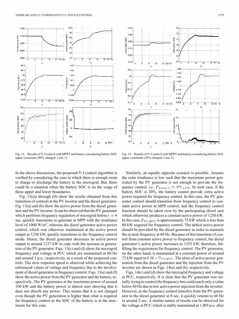
Fig. 13. Results of V-f control withMPPT and battery considering battery SOCupper constraint (80% charged: Case 1).
In the above discussions, the proposed V-f control algorithm isverified by considering the case in which there is enough roomto charge or discharge the battery in the microgrid. But, therecould be a situation when the battery SOC is on the verge ofthese upper and lower boundaries.Fig. 13((a) through (f)) show the results obtained from this
transition of controls at the PV inverter and the diesel generator.Fig. 13(a) and (b) show the active power from the diesel gener-ator and the PV inverter. It can be observed that the PV generatorwhich performs frequency regulation of microgrid beforesec, quickly transitions to generate at MPP with the irradiancelevel of 1000 W/m , whereas the diesel generator active powercontrol, which was otherwise maintained at the active poweroutput at 1250 kW, quickly transitions to the frequency controlmode. Hence, the diesel generator decreases its active poweroutput to around 1237 kW to cope with the increase in genera-tion of the PV generator. Figs. 13(c) and (d) show the microgridfrequency and voltage at PCC which are maintained at 60 Hzand around 1 p.u., respectively, as a result of the proposed con-trols. The slow response speed is observed while achieving thereferenced values of voltage and frequency due to the involve-ment of diesel generator in frequency control. Figs. 13(e) and (f)show the active power from the PV generator and the battery, re-spectively. The PV generates at the maximum power of around100 kW and the battery power is almost zero showing that itdoes not absorb any power. This means that it is not chargedeven though the PV generation is higher than what is requiredfor frequency control as the SOC of the battery is at the max-imum for this case.
Fig. 14. Results of V-f control withMPPT and battery considering battery SOCupper constraint (20% charged: Case 2).
Similarly, an equally opposite scenario is possible. Assumethe solar irradiance is low such that the maximum power gen-erated by the PV generator is not enough to provide the fre-quency control, i.e., . In such case, if thebattery SOC is 20%, the battery cannot provide extra activepower required for frequency control. In this case, the PV gen-erator control should transition from frequency control to con-stant active power at MPP control, and the frequency controlfunction should be taken over by the participating diesel unitwhich otherwise produces a constant active power of 1250 kW.In this case, is approximately 75 kWwhich is less than80 kW required for frequency control. The deficit active powershould be provided by the diesel generator in order to maintainthe system frequency at 60 Hz. Because of this transition of con-trol from constant active power to frequency control, the dieselgenerator’s active power increases to 1255 kW, therefore, ful-filling the requirement for frequency control. The PV generator,on the other hand, is maintained at a constant power of around72 kW equal to . The plots of active power gen-eration from the diesel generator and the injection from the PVinverter are shown in Figs. 14(a) and (b), respectively.Figs. 14(c) and (d) show the microgrid frequency and voltage
at PCC, respectively. It is clear that the PV generator was ini-tially trying to control the frequency but could reach only a valuebelow 60Hz due to low active power injection from the inverter.However, as the frequency control transfers from the PV gener-ator to the diesel generator at 8 sec, it quickly returns to 60 Hzin around 2 sec. A similar nature of results can be observed forthe voltage at PCC which is stably maintained at 1.005 p.u. after

1280 IEEE TRANSACTIONS ON SMART GRID, VOL. 5, NO. 3, MAY 2014
TABLE IIICONTROLLER GAIN PARAMETERS FOR P-Q CONTROL (CASE 3)
the transition of controls. Figs. 14(e) and (f) show active poweroutput of the PV generator and the battery. The PV generatesthe MPP power of 75 kW and the battery power is close to zeroshowing that the battery is not able to inject any power in thiscase as SOC is at its minimum limit.
D. Test of P-Q Control
The results of P-Q control with integrated MPPT and batterycontrol is presented in Fig. 15 (a)–(f). Like V-f control, two dif-ferent cases, namely Case 3 and Case 4, are considered for sim-ulation validation of this control as well. Cases 3 and 4 are sim-ilar to Cases 1 and 2 with slight differences which are elaboratedin the following paragraph. The controller gain parameters forCase 3 are given in Table III. The parameters need to be read-justed slightly for Case 4.Here, in Case 3, the critical active power load of amicrogrid is
less than themaximumavailable PVpower (i.e., ,and in Case 4, . Hence, the disturbance for thispart is the load changes which are very common in real opera-tion. Moreover, since coordinated P-Q control method is to bevalidated, the load change is the most representative scenario tostudy the effectiveness of the proposed control. Hence, the solarirradiance is considered constant at 1000 W/m for both cases.Fig. 15(a) shows the active and reactive power from the diesel
generator. The diesel genset produces a constant active powerof 1250 kW throughout the simulation period for both caseswith a slight change in reactive power between the two cases.Fig. 15(b) shows the reference and actual active and reactivepower of the PV inverter. The reference values of active powerrepresent the critical loads of the microgrid as previously men-tioned. The references of the active power for Cases 3 and 4are 50 kW and 120 kW, respectively. Similarly, the referencesof the reactive power for Cases 3 and 4 are 20 kVAR and 70kVAR, respectively. The references are chosen to demonstrateboth charging and discharging processes of the backup batteryenergy storage system. It can be observed from Fig. 15(b) thatthe proposed coordinated controls are capable of serving thecritical loads in as little as 2 seconds.Fig. 15(c) shows the plot of active power from the PV gener-
ator, the inverter injection, and the active power to and from thebattery. In both cases, the power from PV is maintained constantat the MPP power of 100 kW through MPPT controls as shownby the overlapping black and gray solid curves. The active powerinjection from the inverter is maintained at the reference values
Fig. 15. Results of coordinated P-Q control with solar PV including MPPTcontrol and battery control.
of 50 kW and 120 kW in Cases 3 and 4, respectively. These ref-erence values are demanded by the critical loads. The generationfrom PV in Case 3 is more than the critical load by 50 kW. Thus,this surplus power is sent to charge the lead acid battery which isshown by the 5th (Pbatt Case3) curve in Fig. 15(c). The negativesign of power from the battery shows that it is being charged.ForCase 4, the critical load is greater than the PVgeneration at
MPP and the deficit power of 20 kW is supplied by the battery asshown by the 6th (Pbatt Case4) curve in Fig. 15(c). As explainedearlier, the positive sign of power from the battery shows thatit is being discharged. Therefore, for Case 3, the power injec-tion from the inverter comes only from the solar PV generator.However, in Case 4, the injection comes from PV and battery.Fig. 15(d) shows the SOC of the battery. It is clear that the
SOC increases in Case 3 and decreases in Case 4 as expectedbecause of the respective charging and discharging scenarios. Italso validates the effectiveness of the battery control algorithmadopted in controlling the bidirectional power flow to and fromthe battery.Fig. 15(e) shows the DC side voltage at the inverter input. It
is stably maintained at around 1012 V and 740 V for Cases 3and 4, respectively. It validates the indirect control of the DCside voltage through the power balance between AC and DCsides of the inverter. Similarly, Fig. 15(f) shows the active powermeasured at the DC and AC sides of the inverter. Clearly, theDC side active power is slightly greater than the AC side powerwhich means that the control algorithm also takes care of the ef-ficiency of the inverter in the model. Hence, the effectiveness ofthe proposed coordinated P-Q control algorithm in microgridsis clearly demonstrated from the presented results.

ADHIKARI AND LI: COORDINATED V-F AND P-Q CONTROL 1281
VII. CONCLUSION
The contribution of this paper can be summarized as follows:• This paper proposes and presents coordinated strategies ofV-f control and P-Q control, respectively, for microgridswith PV generator and battery storage.
• In the control strategies, the PV generator is operatedat MPP, and the battery storage acts as a buffer in orderto inject and absorb deficit or surplus power by usingthe charge/discharge cycle of the battery. The papercontributes in demonstrating the control strategies witheffective coordination between inverter V-f (or P-Q) con-trol, MPPT control, and energy storage control.
• The proposed control strategy also provides a smooth tran-sition of PV side PQ control in grid connected mode to V-fcontrol in islanded mode. This is the most essential featurerequired in the modern microgrid controllers.
• The proposed control algorithms are also capable of han-dling the battery SOC constraint. An effective seamlesstransformation of controls from V-f to constant activepower and voltage control at the PV side and from con-stant active power control to frequency control at thediesel generator is validated with satisfactory results.This feature helps the controller to adapt to the changingirradiance levels while considering the battery availability.
• The proposed V-f control method shows a very satisfac-tory performance in reviving highly reduced voltage andfrequency back to the nominal values in a matter of only2 seconds. It is much faster than the diesel generator con-trol which takes around 10 seconds to settle down. Hence,PV and battery installations might be applied effectively inrestoring the microgrid frequency and the voltage at PCCafter disturbances.
• Similarly, the proposed integrated and coordinated P-Qcontrol algorithm can be effectively used in supplying somecritical loads of a microgrid with solar PV and battery.
In the present methods, the control parameters are dependentupon the PV, battery, and external grid conditions and must bere-tuned with the changing conditions. This can be overcome byusinganadaptivemethod toobtain theseparametersdynamicallybased on the system conditions. The adaptive control methodscouldbeaveryuseful andpromising futuredirectionof thiswork.
REFERENCES[1] R. H. Lasseter, “MicroGrids,” in Proc. IEEE Power Engineering So-
ciety Winter Meeting, 2002, vol. 1, pp. 305–308.[2] S. Chowdhury, S. P. Chowdhury, and P. Crossley, “Microgrids and Ac-
tiveDistributionNetworks,” 2009, IETRenewable Energy Series 6.[3] H. Saadat, Power System Analysis, 2nd ed. NewYork, NY, USA:Mc-
Graw Hill, 2002.[4] J. A. P. Lopes, C. L. Moreira, and A. G. Madureira, “Defining con-
trol strategies for MicroGrids islanded operation,” IEEE Trans. PowerSyst., vol. 21, pp. 916–924, 2006.
[5] B. Awad, J. Wu, and N. Jenkins, “Control of distributed generation,”Electrotechn. Info. (2008), vol. 125/12, pp. 409–414.
[6] J. C. Vasquez, J. M. Guerrero, E. Gregorio, P. Rodriguez, R. Teodor-escu, and F. Blaabjerg, “Adaptive droop control applied to distributedgeneration inverters connected to the grid,” in Proc. 2008 IEEE ISIE,pp. 2420–2425.
[7] H. Bevrani and S. Shokoohi, “An intelligent droop control for simulta-neous voltage and frequency regulation in islanded microgrids,” IEEETrans. Smart Grid, vol. 4, no. 3, pp. 1505–1513, Sep. 2013.
[8] J. C. Vasquez, J. M. Guerrero, M. Savaghebi, and R. Teodorescu,“Modelling, analysis and design of stationary reference frame droopcontrolled parallel three-phase voltage source inverters,” in Proc. 2011IEEE 8th ICPE & ECCE, pp. 272–279.
[9] T. L. Vandoorn, B. Meersman, J. D. M. De Kooning, and L. Vande-velde, “Analogy between conventional grid contro and islanded mi-crogrid control based on a global DC-link voltage droop,” IEEE Trans.Power Delivery, vol. 27, no. 3, pp. 1405–1414, Jul. 2012.
[10] H. Laaksonen, P. Saari, and R. Komulainen, “Voltage and frequencycontrol of inverter based weak LV network microgrid,” presented atthe Int. Conf. Future Power Syst., Amsterdam, The Netherlands, Nov.18, 2005.
[11] J. C. Vasquez, R. A. Mastromauro, J. M. Guerrero, and M. Liserre,“Voltage support provided by a droop-controlled multifunctional in-verter,” IEEE Trans. Ind. Electron., vol. 56, pp. 4510–4519, 2009.
[12] H. Li, F. Li, Y. Xu, D. T. Rizy, and J. D. Kueck, “Adaptive voltagecontrol with distributed energy resources: Algorithm, theoretical anal-ysis, simulation and field test verification,” IEEE Trans. Power Syst.,vol. 25, pp. 1638–1647, Aug. 2010.
[13] H. Li, F. Li, Y. Xu, D. T. Rizy, and S. Adhikari, “Autonomous andadaptive voltage control using multiple distributed energy resources,”IEEE Trans. Power Syst., vol. 28, no. 2, pp. 718–730, May 2013.
[14] L. D. Watson and J. W. Kimball, “Frequency regulation of a microgridusing solar power,” in Proc. 2011 IEEE APEC, pp. 321–326.
[15] M. G. Molina and P. E. Mercado, “Modeling and control of grid-con-nected photovoltaic energy conversion system used as a dispersed gen-erator,” in Proc. 2008 IEEE/PES Transm. Distrib. Conf. Expo.: LatinAmerica, pp. 1–8.
[16] N. Kakimoto, S. Takayama, H. Satoh, and K. Nakamura, “Powermodulation of photovoltaic generator for frequency control of powersystem,” IEEE Trans. Energy Conv., vol. 24, pp. 943–949, 2009.
[17] T. Ota, K. Mizuno, K. Yukita, H. Nakano, Y. Goto, and K.Ichiyanagi, “Study of load frequency control for a microgrid,” inProc. 2007AUPEC Power Eng. Conf., pp. 1–6.
[18] L. Xu, Z. Miao, and L. Fan, “Coordinated control of a solar batterysystem in amicrogrid,” inProc. 2012 IEEE/PES Transm. Distrib. Conf.Expo. (T&D), pp. 1–7.
[19] M. G. Villalva, J. R. Gazoli, and E. R. Filho, “Comprehensive ap-proach to modeling and simulation of photovoltaic arrays,” IEEETrans. Power Electron., vol. 24, no. 5, pp. 1198–1208, 2009.
[20] Y. Xu, H. Li, D. T. Rizy, F. Li, and J. D. Kueck, “Instantaneous activeand nonactive power control of distributed energy resources with a cur-rent limiter,” inProc. IEEEEnergy Conversion Congr. Expo., 2010, pp.3855–3861.
[21] O. Tremblay and L. A. Dessaint, “Experimental validation of a batterydynamic model for EV applications,”World Electric Vehicle J., vol. 3,2009.
[22] Y. Xu, F. Li, D. T. Rizy, and J. D. Kueck, “Active and nonactive powercontrol with distributed energy resources,” in Proc. 2008 40th NorthAmerican Power Symp. NAPS’08, pp. 1–7.
[23] S. Adhikari et al., “Utility-side voltage and PQ control with inverter-based photovoltaic systems,” in Proc. 18th World Congr. IFAC, Milan,Italy, Aug. 28–Sep. 2 2011, pp. 6110–6116.
Sarina Adhikari (S’08) received the B.E. degree inelectrical engineering from Institute of Engineering,Pulchowk Campus, Pulchowk, Lalitpur, Nepal, in2002 and the M.E. degree in electrical power systemsmanagement from Asian Institute of Technology,Pathumthani, Thailand, in 2005. She is currentlypursuing the Ph.D. degree in electrical engineering atThe University of Tennessee, Knoxville, TN, USA.Her research interests are voltage stability,
distributed energy resources and integration andcontrols of renewable energy in distribution systems.
Fangxing (Fran) Li (M’01–SM’05) received thePh.D. degree from Virginia Tech, Blacksburg, VA,USA, in 2001.He is presently an Associate Professor at The Uni-
versity of Tennessee at Knoxville and the Directorof the Education Program of the CURENT researchcenter. He was a principal consulting R&D engineerat ABB Consulting prior to joining UT. His area ofinterests include distributed energy resources, micro-grids, renewable energy integration, power marketsand power system computing.
Prof. Li is a registered Professional Engineer in North Carolina, an Editor ofIEEE Transactions on Sustainable Energy, and a Fellow of IET.
![dg;g k'j{tof/L sfo{{ of]hgf, @)&^ alb{ofdrrportal.gov.np/uploads/document/1548.pdfalb{of /fli6«o lgs'~h tyf dWojtL{ If]q 1,08,500 53.58 % /fli6«o jg If]q -emf8L j' ofg ;d]t _ 21,700](https://static.fdocuments.in/doc/165x107/5ecbf21fcd8cec33b0694b46/dgg-kjtofl-sfo-ofhgf-alb-albof-fli6o-lgsh-tyf-dwojtl-ifq.jpg)


![fli6«o ljsf; ;d:of ;dfwfg ;ldltsf] pGgfO;f}+ a}7s · PDF file#= /fli6«o ljsf; ;d:of ;dfwfg ;ldltsf] ljut a}7saf6 ... 6 3,98,95 1,16,76 1,02,39 6,18,10 ... hgfx?sf] k|ult l:ylt b]xfo](https://static.fdocuments.in/doc/165x107/5aa137c97f8b9ada698b52ba/fli6o-ljsf-dof-dfwfg-ldltsf-pggfof-a7s-fli6o-ljsf-dof-dfwfg-ldltsf.jpg)

![!( 2014 i7 ^ bnx¿n] ‘Joj;foL s/ · 2014 k[i7 ^ d"No ¿= %.– AdArshA sAmAj NAtioNAl dAily / fli6«o b} lgs / fli6«o æsÆ ju{ Study in Poland Apace international institute P.](https://static.fdocuments.in/doc/165x107/5f55c0099ea6200f80412ce5/-2014-i7-bnxn-ajojfol-s-2014-ki7-dno-a-adarsha-samaj.jpg)

![fli6«o Ifo/f]u sfo{qmd National Tuberculosis Center National Tuberculosis Programme Nepal Dr. Rajendra Pant Director.](https://static.fdocuments.in/doc/165x107/56649e045503460f94af0d5f/fli6o-ifofu-sfoqmd-national-tuberculosis-center-national-tuberculosis.jpg)


![u|] f ljjflbt ljifodf wf/ · x/]s rf8kj{ Pjd\ ;f+: s[ lts k/ Dk/ fx? b] zsf / fli6«o klxrfg u'Dg' xf]. / fli6«o klxrfgsf] hu] gf{ sf nflu klg rf8kj{Pjd\ ;f+: s[ lt k/ Dk/ fsf]](https://static.fdocuments.in/doc/165x107/5f5e904667a3be752327b802/u-f-ljjflbt-ljifodf-wf-xs-rf8kj-pjd-f-s-lts-k-dk-fx-b-zsf-fli6o.jpg)

