(127) MODEL SF20110 SAND FILTER PUMP ENGLISH 7.5” X …
27
(127) MODEL SF20110 SAND FILTER PUMP ENGLISH 7.5” X 10.3” PANTONE 295U 06/26/2012 127 English Sand Filter Pump Model SF20110 IMPORTANT SAFETY RULES Read, understand, and follow all instructions carefully before installing and using this product. Don’t forget to try these other fine Intex products: Pools, Pool Accessories, Inflatable Pools and In-Home Toys, Airbeds and Boats available at fine retailers or visit our website. Due to a policy of continuous product improvement, Intex reserves the right to change specifications and appearance, which may result in updates to the instruction manual, without notice. OWNER’S MANUAL IMPORTANT! DO NOT RETURN PRODUCT TO STORE To purchase parts and accessories or to obtain non-technical assistance, Visit www.intexcorp.com For technical assistance and missing parts call us toll-free (for U.S. and Canadian Residents): 1-800-234-6839 Monday through Friday, 8:30am to 5:00pm Pacific Time 127-***-R0-1306 For illustrative purposes only.
Transcript of (127) MODEL SF20110 SAND FILTER PUMP ENGLISH 7.5” X …

(127) MODEL SF20110 SAND FILTER PUMP ENGLISH 7.5” X 10.3” PANTONE 295U 06/26/2012
127English
Sand Filter PumpModel SF20110
IMPORTANT SAFETY RULESRead, understand, and follow
all instructions carefully before installing and using this product.
Don’t forget to try these other fine Intex products: Pools, Pool Accessories, Inflatable Pools and In-Home Toys, Airbeds and Boats available at fine retailers or visit our website.Due to a policy of continuous product improvement, Intex reserves the right to change specifications and appearance, which may result in updates to the instruction manual, without notice.
OWNE
R’S
MAN
UAL
IMPORTANT!DO NOT RETURN PRODUCT TO STORE
To purchase parts and accessories or to obtain non-technical assistance,
Visit www.intexcorp.comFor technical assistance and missing parts call us toll-free (for U.S. and Canadian Residents):
1-800-234-6839Monday through Friday, 8:30am to 5:00pm Pacific Time
127-***-R0-1306
For illustrative purposes only.

(127) MODEL SF20110 SAND FILTER PUMP ENGLISH 7.5” X 10.3” PANTONE 295U 06/26/2012
127
SAVE THESE INSTRUCTIONS Page 2
English
TA
BLE
OF
CO
NT
EN
TS
Warnings.......................................................................... 3
Parts List & References.................................................. 4-8
Setup Instructions ......................................................... 9-16
Product Specifications................................................... 11
Operating Instructions ................................................... 17-19
Intex Pools Operating Time Table.................................. 20
Non-Intex Pools Operating Time Table.......................... 21
Maintenance.................................................................... 22
Long Term Storage.......................................................... 23
Troubleshooting Guide................................................... 24
Common Pool Problems................................................. 25
General Aquatic Safety................................................... 26
Limited Warranty............................................................. 27

(127) MODEL SF20110 SAND FILTER PUMP ENGLISH 7.5” X 10.3” PANTONE 295U 06/26/2012
127
SAVE THESE INSTRUCTIONS Page 3
English
SA
FET
Y R
ULE
SIMPORTANT SAFETY RULESRead, Understand and Follow All Instructions Carefully Before Installing and Using this Product.
READ AND FOLLOW ALL INSTRUCTIONSWARNING
• To reduce the risk of injury, do not permit children to use this product. Always supervise children and those with disabilities.• Children must stay away from this product and electrical cord(s).• Assembly and disassembly by adults only.• Risk of electric shock. Connect only to a grounding type receptacle, this product is provided with a ground-fault circuit interrupter. If replacement of the plug or cord is needed, use only identical replacement parts.• Always unplug this product from the electrical outlet before removing, cleaning, servicing or making any adjustment to the product.•Theunitisprovidedwithaground-faultcircuitinterrupter(GFCI).TotesttheGFCI, push the test button. TheGFCIshouldinterruptpower.Push the reset button, powershouldberestored.IftheGFCIfailstooperateinthismanner.TheGFCIis defective.IftheGFCIinterruptspowertothepumpwithoutthetestbuttonbeing pushed, a ground current is flowing, indicating the possibility of an electric shock. Do not use this pump. Disconnect the pump and have the problem corrected by a qualified service representative before using.• Do not bury the electrical cord. Locate the cord where it will not be damaged by lawn mowers, hedge trimmers and other equipment.• To reduce the risk of electric shock, replace damaged cord immediately. Use a qualified electrician to replace the cord.• To reduce the risk of electric shock, do not use extension cords, timers, plug adaptors or converter plugs to connect unit to electric supply; provide a properly located outlet.• Do not attempt to plug in or unplug this product while standing in water or when your hands are wet.• Donotuseanapplianceleakagecurrentinterrupter(ALCI)inplaceofaGFCI since the ALCI will not protect people.•Positionthisproductawayfrompool,soastopreventchildrenfromclimbingonit and access the pool.• Do not operate this product when pool is occupied.• To reduce the risk of entrapment hazard, never enter the pool if suction strainer component is loose, broken, cracked, damaged or missing. Replace loose, broken, damaged, cracked or missing suction strainer components immediately.•Neverplayorswimnearsuctionfittings.Yourbodyorhairmaybetrappedcausing permanent injury or drowning.•Topreventequipmentdamageandriskofinjury,alwaysturnpumpoffbefore changing the filter control valve position.•Neveroperatethisproductabovethemaximumworkingpressurestatedonthe filter tank.•HazardousPressure.Impropertankvalvecoverassemblycouldcausethevalve cover to blow off and cause serious injury, property damage or death.•Thisproductisintendedtobeusedonlyforthepurposesdescribedinthemanual!
FAILURE TO FOLLOW THESE WARNINGS MAY RESULT IN PROPERTY DAMAGE, ELECTRIC SHOCK, ENTANGLEMENT OR OTHER SERIOUS INJURY OR DEATH.
This product is for use with storable pools only. Do not use with permanently-installed pools. A storable pool is constructed so that it is capable of being readily disassembled for storage and reassembled to its original integrity. A permanently-installed pool is constructed in or on the ground or in a building such that it cannot be readily disassembled for storage.
These product warnings, instructions and safety rules provided with the product represent some common risks of water recreation devices and do not cover all instances of risk and danger. Please use common sense and good judgement when enjoying any water activity.
CAUTION

(127) MODEL SF20110 SAND FILTER PUMP ENGLISH 7.5” X 10.3” PANTONE 295U 06/26/2012
127
SAVE THESE INSTRUCTIONS Page 4
PA
RT
S L
IST
NOTE:Drawingsforillustrationpurposeonly.Actualproductmayvary.Nottoscale.
English
PARTS LIST
7
1
9
4 5
2
6
3
8
10 11 12
13 14 15
16 17 18
20 2119

(127) MODEL SF20110 SAND FILTER PUMP ENGLISH 7.5” X 10.3” PANTONE 295U 06/26/2012
127
SAVE THESE INSTRUCTIONS Page 5
English
PARTS LIST (continued)
PA
RT
S L
IST
NOTE:Drawingsforillustrationpurposeonly.Actualproductmayvary.Nottoscale.
23
25
22 24
26 27
28 29 30
31 32 33
34
Optional Optional
Optional
35 36
37 38

(127) MODEL SF20110 SAND FILTER PUMP ENGLISH 7.5” X 10.3” PANTONE 295U 06/26/2012
127
SAVE THESE INSTRUCTIONS Page 6
English
PA
RT
S R
EFE
RE
NC
EPARTS REFERENCEBefore assembling your product, please take a few minutes to check the contents
and become familiar with all the parts.
NOTE:Drawingsforillustrationpurposeonly.Actualproductmayvary.Nottoscale.
Operation is subject to the following two conditions: (1) this device may not cause interference, and (2) this device must accept any interference, including interference that may cause undesired operation of the device.
Changes or modifications not expressly approved by the party responsible for compliance could void the user’s authority to operate the equipment.
This equipment has been tested and found to comply with the limits for Class B digital device, pursuant to part 15 of the FCC Rules. These limits are designed to provide reasonable protection against harmful interference in a residential installation. This equipment generates, uses and can radiate radio frequency energy and, if not installed and used in accordance with the instructions, may cause harmful interference to radio or television reception, which can be determined by turning the equipment off and on, the user is encouraged to try to correct the interference by one or more of the following measures:• Reorient or relocate the receiving antenna.• Increase the separation between the equipment and the receiver. • Connect the equipment into an outlet on a circuit different from that to which the receiver is connected.• Consult the dealer or an experienced radio/TV technician for help.
1
5
9
11
2
13
35
20
32
3334
19
3
6
7
4
12
15
16
17
11
18
810
14
39
41
40

(127) MODEL SF20110 SAND FILTER PUMP ENGLISH 7.5” X 10.3” PANTONE 295U 06/26/2012
127
SAVE THESE INSTRUCTIONS Page 7
English
PA
RT
S R
EFE
RE
NC
EPARTS REFERENCE (continued)Before assembling your product, please take a few minutes to check the contents
and become familiar with all the parts.
NOTE:Drawingsforillustrationpurposeonly.Actualproductmayvary.Nottoscale.
21
22
23 28 29 30
21
22
23 28 29 31
21
22
23 24 25 26
21
22
23 24 25 26 27
36
37
37
37
37

(127) MODEL SF20110 SAND FILTER PUMP ENGLISH 7.5” X 10.3” PANTONE 295U 06/26/2012
127
SAVE THESE INSTRUCTIONS Page 8
English
When ordering parts, be sure to quote the model number and part numbers.
PARTS REFERENCE (continued)Before assembling your product, please take a few minutes to check the contents
and become familiar with all the parts.
PA
RT
S R
EFE
RE
NC
E
REF. NO. DESCRIPTION QTY. SPARE PART NO.
1 PRESSUREGAUGE 1 112242 6-WAYVALVE 1 114963 DRAINOUTLETCOVER 1 111314 CLAMP 1 113805 TANKO-RING 1 113796 SANDSHIELD 1 113827 CENTERPIPEHUB 1 114958 LATERAL 10 113849 DRAINVALVECAP 1 11456
10 DRAINVALVEO-RING 1 1138511 L-SHAPEO-RING 4 1122812 HOSEWITHNUTS 2 1100913 SANDFILTERINTERCONNECTINGHOSE 1 1153514 LEAFTRAPNUT 1 1147915 LEAFTRAPO-RING 1 1123216 BASKET 1 1126017 FILTERHOUSINGNUT 1 1126118 L-SHAPEO-RING 1 1141219 SEDIMENTRELEASEVALVE 1 1046020 VALVEO-RING 1 1026421 PLUNGERVALVE(HOSEO-RING&STEPWASHERINCLUDED) 2 10747E22 HOSEO-RING 2 1026223 STEPWASHER 2 1074524 STRAINERNUT 2 1025625 FLATSTRAINERRUBBERWASHER 2 1025526 THREADEDSTRAINERCONNECTOR 2 1074427 ADJUSTABLEPOOLINLETNOZZLE 1 1107428 ADAPTOR B 2 1072229 STRAINERCONNECTOR 2 1107030 POOLINLETNOZZLE 1 1107131 STRAINERGRID 1 1107232 SCREW 2 1138133 PUMPMOTOR&CONTROL 1 11322EG34 PRE-FILTERASSEMBLY 1 1137135 LEAF TRAP COVER 1 1148036 STRAINERGRID 1 1025337 VACUUM RELEASE VALVE 2 1143738 VACUUM RELEASE VALVE CAP 2 1157639 SANDFILTERPUMPMOTORINLET O-RING 2 11457 40 16”SANDFILTERPUMPANDCOMBOTANK 1 1149741 16”SANDFILTERPUMPTANKBASE 1 11514

(127) MODEL SF20110 SAND FILTER PUMP ENGLISH 7.5” X 10.3” PANTONE 295U 06/26/2012
127
SAVE THESE INSTRUCTIONS Page 9
English
SE
TU
P I
NS
TR
UC
TIO
NS
The strainer grid prevents large objects from jamming and/or damaging the filter pump. If your pool has an inflatable top ring, install the strainer, nozzle and plunger valve before inflating the pool liner top ring. The part numbers here onward refer to the parts depicted in the Parts List section of this manual. To install, do the following:
1. In a counter-clockwise motion unscrew plunger valve union from the threaded strainer connector (26) (see drawing 1). Be careful not to lose the step rubber washer (23). Place the plunger valve on the ground in a safe place.2. In a counter-clockwise motion unscrew the strainer nut (24) from the threaded connector (26). Leave the flat washer (25) on the connector (26).3. Install the strainer and plunger valve at the lower position of pool outlet (marked "+"). From the inside of the pool liner insert the connector (26) into one of the pre-cut holes with the washer remaining on the connector to be placed against the inside of the liner wall.4. Before assembly, lubricate the threads with a petroleum jelly. With the flat side of the strainer nut (24) facing the outside wall of the liner in a clockwise motion screw the strainer nut (24) back onto the threaded connector (26) (see drawing 2). 5. Finger tighten the strainer nut (24) onto the threaded connector (26).6. Grasptheplungervalveassembly.Make sure the step washer (23) is in place.7. In a clockwise motion screw the plunger valve union back onto the threaded connector (26) (see drawing 3).8. In a clockwise motion turn the plunger valve handle to close position. Ensure the plunger valve is securely closed. This will prevent water from flowing out during filling of the pool (see drawing 4.1).9. NOTE: Nevercoverthevacuumrelease valve (37) unless it is damaged or leaking. Replace the vacuum release valve immediately.
POOL OUTLET - STRAINER & PLUNGER VALVE SETUP
1
2
3
25 26
INSIDE LINER WALL
24
4.2
2
1
1
2
4.1
INSIDE LINER WALL
23
36
WATER FLOW
POOL
37

(127) MODEL SF20110 SAND FILTER PUMP ENGLISH 7.5” X 10.3” PANTONE 295U 06/26/2012
127
SAVE THESE INSTRUCTIONS Page 10
English
SE
TU
P I
NS
TR
UC
TIO
NSPOOL INLET - NOZZLE & PLUNGER VALVE SETUP
1. In a counter-clockwise motion unscrew plunger valve union from the threaded strainer connector (26) (see drawing 5). Be careful not to lose the step rubber washer (23). Place the plunger valve on the ground in a safe place.2. In a counter-clockwise motion unscrew the strainer nut (24) from the threaded connector (26). Leave the flat washer (25) on the connector (26).3. Install the nozzle and plunger valve at the upper position of pool inlet. From the inside of the pool liner insert the connector (26) into one of the pre-cut holes with the washer remaining on the connector to be placed against the inside of the liner wall.4. Before assembly, lubricate the threads with a petroleum jelly. With the flat side of the strainer nut (24) facing the outside wall of the liner in a clockwise motion screw the strainer nut (24) back onto the threaded connector (26) (see drawing 6). 5. Finger tighten the adjustable pool inlet nozzle (27) and the strainer nut (24) onto the threaded connector (26).6. Grasptheplungervalveassembly.Make sure the step washer (23) is in place.7. In a clockwise motion screw the plunger valve union back onto the threaded connector (26) (see drawing 7).8. In a clockwise motion turn the plunger valve handle to close position. Ensure the plunger valve is securely closed. This will prevent water from flowing out during filling of the pool (see drawing 8).9. NOTE: Nevercoverthevacuumrelease valve (37) unless it is damaged or leaking. Replace the vacuum release valve immediately.10. Adjust the direction of the nozzle head pointing away from the pool outlet for a better circulation result (see drawing 9). 11. The pool liner is now ready to be filled with water. Consult the above-ground-pool owner’s manual for the filling instructions.
POOL
9
52
1
7
1
2
8
INSIDE LINER WALL
6
25 26 27
INSIDE LINER WALL
24
WATER FLOW
37

(127) MODEL SF20110 SAND FILTER PUMP ENGLISH 7.5” X 10.3” PANTONE 295U 06/26/2012
127
SAVE THESE INSTRUCTIONS Page 11
English
PROD
UCT
SPEC
S &
SETU
P IN
STRU
CTIO
NSPRODUCT SPECIFICATIONS
SETUP INSTRUCTIONS
Power: 110-120 Volt ACAmperage: 6.0 AMaximum working pressure: 3.5 bar (50 psi)Effective filtering area: 0.13 m2 (1.44 ft2)Maximum Flow Rate: 10030 liters/hour (2650 gallons/hour)Recommended filtering media: No.20silicasandorglasssand.Particlesize(Notincluded) range 0.45 to 0.85 mm (0.018 to 0.033 inches). Uniformity Coefficient less than 1.75.Recommended filtering media quantity: No.20silicasand45Kg(100Lbs)or glass sand 32Kg(70Lbs).Limited Warranty: see “Limited Warranty”
NOTE: NOTSUITABLEFORUSEWITHKCP-LOW-SALTAUTOMATICSALTWATERSYSTEM(MODEL6110/6220)
The sand filter removes suspended particles but does not sanitize your pool. Pool chemistry is a specialized area and you should consult your local pool service specialist for details.
TOOLS REQUIRED: One (1) Phillips screwdriverPump location and mounting:• Thesystemmustbeinstalledonasolidlevelandvibration-freebase.• Providealocationprotectedfromtheweather,moisture,floodingand freezing temperature.• Provideadequateaccess,spaceandlightingforroutinemaintenance.• Pumpmotorrequiresfreecirculationofairforcooling.Donotinstall the pump in a damp or non-ventilated location.
A team of 2 or more people is recommended for setting up this product.
Motor pre-filtering assembly setup:1. Remove the sand filter and its accessories from the packaging carefully and inspect for any visible damage. If parts are damaged contact your local service center listed at the back of this owner’s manual.2. In a counter-clockwise motion unscrew the leaf trap cover (14) from the pre-filter housing. Take out the basket (16) and filter housing nut (17) (see drawing 10). 3. Connect the pre-filter housing to the motor waterinlet.Note: Align the connector in the pre-filter housing with the water inlet on the motor (see drawing 11).
10
11
35
17
16
14

(127) MODEL SF20110 SAND FILTER PUMP ENGLISH 7.5” X 10.3” PANTONE 295U 06/26/2012
127
SAVE THESE INSTRUCTIONS Page 12
English
4. In a clockwise motion screw filter housing nut (17) onto the motor water inlet (See drawings 12.1 & 12.2).
5. Replace the basket (16) and leaf trap cover (14) back to the pre-filter housing (See drawings 13.1 & 13.2).
SETUP INSTRUCTIONS (continued)
SE
TU
P I
NS
TR
UC
TIO
NS
Sand tank installation:1. Place the tank support base on the selected location.2. Place the tank on the tank support base (See drawing 14.1).3. Connect the motor pre-filtering assembly unit to the tank support base (See drawing 14.2). NOTE: Ensure the pre-filter housing water inlet hose connection is facing towards the pool. IMPORTANT: Some countries, especially in the European community, require the product to be secured to the ground or to a base in a permanent upright position. Check your local authorities to determine if there is a regulation in your area regarding above-the-ground swimming pool filter-pumps. If yes, then the product can be mounted to a platform using the two holes located in the base. See drawing 14.3. The product can be mounted on a cement base or onto a wooden plat form to prevent accidental falling over. • Themountingholesare6.4mmindiameterandspaced(177.4mm) apart. • Usetwoboltsandlocknutswithamaximumof6.4mmindiameter.
12.212.1
13.1 13.2
14.1 14.2
6.98in(177.4m
m)
14.3
17 17
14
1635

(127) MODEL SF20110 SAND FILTER PUMP ENGLISH 7.5” X 10.3” PANTONE 295U 06/26/2012
127
SAVE THESE INSTRUCTIONS Page 13
English
SETUP INSTRUCTIONS (continued)
SE
TU
P I
NS
TR
UC
TIO
NS
Sand loading: IMPORTANT: Use No. 20 silica sand or glass sand with particle size range 0.45 to 0.85 mm (0.018 to 0.033 inches) and a Uniformity Coefficient less than 1.75.
NOTE: Before loading the tank with sand, ensure the center pipe hub assembly is securely in place at the bottom of the tank, and vertically centered inside the tank.
1. Place the sand shield (6) over the top of the center pipe. Pour the sand into the tank at a slow rate. (see drawing 15).2. Fill the tank approximately half way, remove the sand shield (6) from the top. (see drawing 16).
3. Evenly distribute the sand inside the tank, then fill the tank with some water to provide a cushioning effect when the remaining sand is poured in. This prevents the center pipe hub (7) from excessive shock (see drawing 17). Place the sand shield (6) back and continue to pour the sand into the tank.4. Sandshallbefilledbetweenthe“MAX”and“MIN”markedgaugeonthecenter pipe. Evenly spread and level out the sand by hand (see drawings 17 & 18).
5. Remove the sand shield (6).6. Wash away all sand around the top edge of the tank.
15 16
66
MAX
MIN
17
MAX
MIN
MAX
MIN
187
7

(127) MODEL SF20110 SAND FILTER PUMP ENGLISH 7.5” X 10.3” PANTONE 295U 06/26/2012
127
SAVE THESE INSTRUCTIONS Page 14
English
6-way valve installation:1. Lower the 6-way valve over the tank slowly, and ensure the bypass pipe protruding underneath the 6-way valve fits securely into the center pipe hub (7) top opening (see drawing 19).
IMPORTANT: There are three hose connection ports on the 6-way valve, ensure the outlet connection (from filter to the pool) on the valve is facing towards the pool, and the inlet connection (from motor to valve) is aligned with the motor outlet (see drawing 20).
SE
TU
P I
NS
TR
UC
TIO
NSSETUP INSTRUCTIONS (continued)
WARNINGImproper tank valve and clamp assembly could cause the valve and clamp to blow off and cause serious injury, property damage or death.
20WATER INLET
WATER OUTLET
2. Place an L-shape o-ring (11) on the 6-way valve inlet connection and on the pump motor outlet. In a clockwise motion connect the sand filter interconnecting hose (13) between the pump motor outlet and the 6-way valve inlet connection (see drawing 21).3. Remove the clamp bolt, and install the clamp around the tank and 6-way valve flanges, then replace the clamp bolt and use a phillips screwdriver (not included) to tighten it (see drawings 22).
19
21 22
7
13 4

(127) MODEL SF20110 SAND FILTER PUMP ENGLISH 7.5” X 10.3” PANTONE 295U 06/26/2012
127
SAVE THESE INSTRUCTIONS Page 15
English
SE
TU
P I
NS
TR
UC
TIO
NSSAND FILTER PUMP HOSE CONNECTION SETUP
The 6-way valve has three hose connection ports.1. Connect one hose (12) end to the pre-filter inlet and the other end of the hose to the lower plunger valve with the strainer. Ensure the hose nuts are securely tightened.2. Connect the second hose (12) between the 6-way valve water outlet and the upper plunger valve with the inlet-nozzle. Ensure the hose nuts are securely tighten.3. The third hose connection port (drain/waste outlet) on the 6-way valve shall be directed to a proper draining receptacle using a hose or pipe (not provided). Remove the drain cap before attaching the drain/waste hose or pipe. 4. The sand filter pump is now ready to filter the pool.
WARNING• Positionthisproductawayfromthepool,soastopreventchildrenfrom climbing on it and accessing the pool.
(ILLUSTRATION NOT TO SCALE)
6-WAY VALVE
WATER INLET
WATER OUTLET
MOTOR MOTOR WATEROUTLET
PRE-FILTER
WATER INLET
WATER LEVEL
ADJUSTABLE POOL INLET
NOZZLE
STRAINER GRID
OUTSIDE LINER WALL
PLUNGER VALVE
POWER CORD
L-SHAPE O-RING
L-SHAPE O-RING
TO DRAIN

(127) MODEL SF20110 SAND FILTER PUMP ENGLISH 7.5” X 10.3” PANTONE 295U 06/26/2012
127
SAVE THESE INSTRUCTIONS Page 16
English
SE
TU
P I
NS
TR
UC
TIO
NSSAND FILTER PUMP HOSE CONNECTION SETUP (continued)
For INTEX pool size 16' and below:1. In a counter-clockwise motion unscrew plunger valve union from the threaded strainer connector (26). Be careful not to lose the step rubber washer (23).2. Grasptheplungervalveassembly.Makesurethestepwasher(23) is in place. Connect adaptor B (28) to plunger valve union.3. Remove wall plug and then insert the strainer (29 & 31) into the lower position of protruding hose connection, and the nozzle (29 & 30) into the upper position of protruding hose connection. Adaptor B (28) fits over the strainer connection (29) inserted into the connection. Tighten securely.4. Remove the drain cap (3) before attaching the drain/waste hose or pipe.
For NON-INTEX pool:Connect the hose (12) to the pool inlet/outlet connection with a large hose clamp. Tighten securely. Remove the drain cap (3) before attaching the drain/waste hose or pipe.
POOL
LARGE HOSE CLAMP
POOL
12
3
29 & 30
29 & 31
3

(127) MODEL SF20110 SAND FILTER PUMP ENGLISH 7.5” X 10.3” PANTONE 295U 06/26/2012
127
SAVE THESE INSTRUCTIONS Page 17
English
OP
ERAT
ING
INST
RUCT
IONSOPERATING INSTRUCTIONS
• Riskofelectricshock.Connectthisproductonlytoagroundingtype receptacle protected by a ground-fault circuit interrupter (GFCI) or residual current device (RCD). Contact a qualified electrician if you cannot verify that the receptacle is protected by a GFCI/RCD. Use a qualified electrician to install the GFCI/RCD, which has a maximum rate of 30mA. Do not use a portable residual current device (PRCD). • To reduce the risk of electric shock, do not use extension cords, timers, plug adaptors or converter plugs to connect unit to electric supply; provide a properly located outlet. • Do not attempt to plug in or unplug this product while standing in water or when your hands are wet. • Neveroperatethisproductabovethemaximumworkingpressurestated on the filter tank. • Alwaysswitchoffpumpbeforechangingthe6-wayvalveposition. • Operatingthisproductwithoutwaterflowingthroughthesystemcan cause a build up of hazardous pressure which can result in an explosive situation, serious injury, property damage or death. • Nevertestthispumpwithcompressedair.Neveroperatethesystemwith water temperature above 35° C (95° F).
Valve Position Function Water Flow DirectionFILTER
(see drawing 23)Normalfiltrationandregular vacuuming of pool
From pump through filter media to pool
BACKWASH(see drawing 24)
Reverses water flow to clean filter media
From pump through filter media to valve waste/drain outlet
RINSE(see drawing 25)
For initial startup cleaning of the sand, and leveling the sand bed after backwashing
From pump through filter media to valve waste/drain outlet
WASTE(see drawing 26)
For vacuuming directly to waste, lowering pool level or to drain the pool
From pump to valve waste/drain outlet bypassing the filter media
RECIRCULATE(see drawing 27)
For circulating water back to pool without going through the filter media
From pump through valve to pool bypassing the filter media
CLOSED(see drawing 28)
Shuts off all flow to filter and pool “Do not use this setting with pump running”
6-way valve positions and function:
WARNINGRETLI F
ESNI R
ETAL
UCRI
CER
ESOLC
ETSA
W
ESNI R
ETAL
UCRI
CER
HSAW
KCAB
ESOLC
ETSA
W
RETLI FES
NI R
ETAL
UCRI
CER
HSAW
KCAB
ETSA
W
RETLI FES
NI R
ER
HSAW
KCAB
ESOLC
ETSA
W
RETLI FES
NI R
ETAL
UCRI
CER
HSAW
KCAB
ESOLC
RETLI F
ETAL
UCRI
CER
HSAW
KCAB ESOLC
ETSA
W
B
23
RETLI FES
NI R
ETAL
UCRI
CER
ESOLC
ETSA
W
ESNI R
ETAL
UCRI
CER
HSAW
KCAB
ESOLC
ETSA
W
RETLI FES
NI R
ETAL
UCRI
CER
HSAW
KCAB
ETSA
W
RETLI FES
NI R
ER
HSAW
KCAB
ESOLC
ETSA
W
RETLI FES
NI R
ETAL
UCRI
CER
HSAW
KCAB
ESOLC
RETLI F
ETAL
UCRI
CER
HSAW
KCAB ESOLC
ETSA
W
B
24
RETLI FES
NI R
ETAL
UCRI
CER
ESOLC
ETSA
W
ESNI R
ETAL
UCRI
CER
HSAW
KCAB
ESOLC
ETSA
W
RETLI FES
NI R
ETAL
UCRI
CER
HSAW
KCAB
ETSA
W
RETLI FES
NI R
ER
HSAW
KCAB
ESOLC
ETSA
W
RETLI FES
NI R
ETAL
UCRI
CER
HSAW
KCAB
ESOLC
RETLI F
ETAL
UCRI
CER
HSAW
KCAB ESOLC
ETSA
W
B
25

(127) MODEL SF20110 SAND FILTER PUMP ENGLISH 7.5” X 10.3” PANTONE 295U 06/26/2012
127
SAVE THESE INSTRUCTIONS Page 18
English
Initial startup and operation:Before operating, be sure that: • Allthehoseshavebeenconnectedandtightenedsecurely,andcorrectamount of filter sand have been loaded. • Theentiresystemisconnectedtoagroundingtypereceptacleprotectedbya ground-faultcircuitinterrupter(GFCI)orresidualcurrentdevice(RCD).
OP
ERAT
ING
INST
RUCT
IONSOPERATING INSTRUCTIONS (continued)
CAUTIONThe filter control valve has a closed position. The pump should never be on when the valve is in the closed position. If the pump is operated with the valve closed, explosive situation could exist.
1. Turn both plunger valve handles fully counter-clockwise until they stop. This opens the valves to allow water to flow into the sand filter pump. NOTE: The plunger valve is equipped with a vacuum release valve that will automatically activate to minimize the suction at the pool outlet if the outlet is blocked. This is an additional safety feature to prevent suction entrapment. The vacuum release valve will reset once the blockage is removed and the pump is switched off. To restart the system the air must be removed from the filter pump per previous step.2. Ensure the drain/waste outlet on the 6-way valve is not covered and directed to a proper draining receptacle.3. Ensure the pump is off, depress the 6-way valve and turn it to the “BACKWASH” position (see drawings 24 & 29). IMPORTANT: To prevent damage to the 6-way valve, always depress the valve handle before turning. Always switch off pump before changing the 6-way valve position. 4. Switch on the pump (see drawing 30). Water is circulating backward through the sand media and to waste/drain outlet. Backwash until a clear flow of water is observed in the waste/drain outlet or through the drain sediment window. NOTE: The initial backwash of the filter is recommended to remove any impurities or fine sand particles in the sand media.
RETLI FES
NI R
ETAL
UCRI
CER
ESOLC
ETSA
W
ESNI R
ETAL
UCRI
CER
HSAW
KCAB
ESOLC
ETSA
W
RETLI FES
NI R
ETAL
UCRI
CER
HSAW
KCAB
ETSA
W
RETLI FES
NI R
ER
HSAW
KCAB
ESOLC
ETSA
W
RETLI FES
NI R
ETAL
UCRI
CER
HSAW
KCAB
ESOLC
RETLI F
ETAL
UCRI
CER
HSAW
KCAB ESOLC
ETSA
W
B
26
RETLI FES
NI R
ETAL
UCRI
CER
ESOLC
ETSA
W
ESNI R
ETAL
UCRI
CER
HSAW
KCAB
ESOLC
ETSA
W
RETLI FES
NI R
ETAL
UCRI
CER
HSAW
KCAB
ETSA
W
RETLI FES
NI R
ER
HSAW
KCAB
ESOLC
ETSA
W
RETLI FES
NI R
ETAL
UCRI
CER
HSAW
KCAB
ESOLC
RETLI F
ETAL
UCRI
CER
HSAW
KCAB ESOLC
ETSA
W
B
27
RETLI FES
NI R
ETAL
UCRI
CER
ESOLC
ETSA
W
ESNI R
ETAL
UCRI
CER
HSAW
KCAB
ESOLC
ETSA
W
RETLI FES
NI R
ETAL
UCRI
CER
HSAW
KCAB
ETSA
W
RETLI FES
NI R
ER
HSAW
KCAB
ESOLC
ETSA
W
RETLI FES
NI R
ETAL
UCRI
CER
HSAW
KCAB
ESOLC
RETLI F
ETAL
UCRI
CER
HSAW
KCAB ESOLC
ETSA
W
B
28
29
12
30
TIMER OFF ON

(127) MODEL SF20110 SAND FILTER PUMP ENGLISH 7.5” X 10.3” PANTONE 295U 06/26/2012
127
SAVE THESE INSTRUCTIONS Page 19
OP
ERAT
ING
INST
RUCT
IONSOPERATING INSTRUCTIONS (continued)
English
5. Switchoffthepump,changethe6-wayvalveto“RINSE”position(see drawing 25).6. Switch on the pump and run the pump for about one minute to level out the sand bed after backwashing the sand media.7. Switch off the pump, change the 6-way valve to “FILTER” position (see drawing 23).8. Switch on the pump. The system is now operating in the normal filtering mode. Run the pump until the desired pool water clearance is obtained and no more than 12 hours per day.9. Record the initial pressure gauge reading when the filter media is clean. NOTE: During initial setup of the system, it may be necessary to backwash frequently due to unusual heavy dirt present in the water and sand. After that, as the filter removes dirt and impurities from the pool water, the accumulated dirt in the sand media will cause the pressure to rise and the flow to diminish. If there is no vacuuming device attached to the system and the pressure gauge reading is in the yellow zone it is time to backwash the sand media, see “BACKWASH”under“initialstartupandoperation”section. Vacuuming device (i.e. Intex auto pool cleaner) attached to the system may also cause the flow to diminish and the pressure to rise. Remove any vacuuming device from the system and check if the pressure gauge reading has dropped from the yellow zone to the green zone.
Operating the system under “TIMER” mode or manually: To operate the sand filter pump in “FILTER” mode under “TIMER” control: A. Set the timer dial to the desired operating hours. See operation time table (see drawing 31). B. Turn on the pump by pressing the switch to “ ” position, the sand filter pump is now filtering the water and will stop after the operating hours are completed. The built-in timer will now operate for the number of hours selected at the same time each day. C. Operating hours can be re-adjusted if necessary. Follow step A – B. To operate the sand filter pump manually (without the “TIMER” mode): A. Turn on the pump by pressing the switch to “-” position, the sand filter pump is now filtering the water. B. To turn off the pump, press the switch to “O” position.
31
TIMER OFF ON
TIMER DIAL(HOURS)
(127) MODEL SF20110 SAND FILTER PUMP ENGLISH 7.5” X 10.3” PANTONE 295U 06/26/2012
127
SAVE THESE INSTRUCTIONS Page 20
English
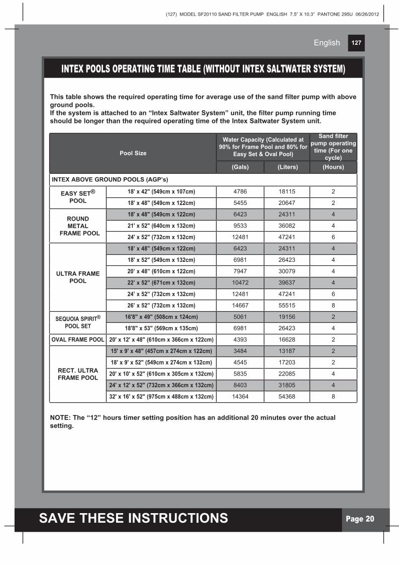
INTEX POOLS OPERATING TIME TABLE (WITHOUT INTEX SALTWATER SYSTEM)
This table shows the required operating time for average use of the sand filter pump with above ground pools.If the system is attached to an “Intex Saltwater System” unit, the filter pump running time should be longer than the required operating time of the Intex Saltwater System unit.
Pool Size
Water Capacity (Calculated at 90% for Frame Pool and 80% for
Easy Set & Oval Pool)
Sand filter pump operating
time (For one cycle)
(Gals) (Liters) (Hours)
INTEX ABOVE GROUND POOLS (AGP’s)
EASY SET® POOL
18' x 42" (549cm x 107cm) 4786 18115 2
18' x 48" (549cm x 122cm) 5455 20647 2
ROUNDMETAL
FRAME POOL
18' x 48" (549cm x 122cm) 6423 24311 4
21' x 52" (640cm x 132cm) 9533 36082 4
24' x 52" (732cm x 132cm) 12481 47241 6
ULTRA FRAMEPOOL
18’ x 48” (549cm x 122cm) 6423 24311 4
18' x 52" (549cm x 132cm) 6981 26423 4
20’ x 48” (610cm x 122cm) 7947 30079 4
22’ x 52” (671cm x 132cm) 10472 39637 4
24’ x 52” (732cm x 132cm) 12481 47241 6
26’ x 52” (732cm x 132cm) 14667 55515 8
SEQUOIA SPIRIT® POOL SET
16'8" x 49" (508cm x 124cm) 5061 19156 2
18'8" x 53" (569cm x 135cm) 6981 26423 4
OVAL FRAME POOL 20' x 12' x 48" (610cm x 366cm x 122cm) 4393 16628 2
RECT. ULTRAFRAME POOL
15' x 9' x 48" (457cm x 274cm x 122cm) 3484 13187 2
18' x 9' x 52" (549cm x 274cm x 132cm) 4545 17203 2
20' x 10' x 52" (610cm x 305cm x 132cm) 5835 22085 4
24' x 12' x 52" (732cm x 366cm x 132cm) 8403 31805 4
32' x 16' x 52" (975cm x 488cm x 132cm) 14364 54368 8
NOTE: The “12” hours timer setting position has an additional 20 minutes over the actual setting.

(127) MODEL SF20110 SAND FILTER PUMP ENGLISH 7.5” X 10.3” PANTONE 295U 06/26/2012
127
SAVE THESE INSTRUCTIONS Page 21
English
NON-INTEX POOLS OPERATING TIME TABLE
This table shows the required operating time for average use of the sand filter pump with above ground pools.
Water Capacity Sand filter pump operating time (For one cycle)
(Gals) (Liters) (Hours)
2
2
2
4
4
4
4
6
6
6
6
6
8
8
8
8
12
12
12
12
12
12
12
12
4000
4440
5000
6000
7000
8000
9000
10000
11000
12000
13000
14000
15000
16000
17000
18000
19000
20000
21000
22000
23000
24000
25000
26000
15140
16805
18925
22710
26495
30280
34065
37850
41635
45420
49205
52990
56775
60560
64345
68130
71915
75700
79485
83270
87055
90840
94625
98410

(127) MODEL SF20110 SAND FILTER PUMP ENGLISH 7.5” X 10.3” PANTONE 295U 06/26/2012
127
SAVE THESE INSTRUCTIONS Page 22
English
MA
INT
EN
AN
CEMOTOR PRE-FILTER CLEANING AND MAINTENANCE
1. Make sure the filter pump is switched off, then disconnect the power cord from the electrical outlet.
2. Turn both plunger valve handles fully clockwise until they stop. This closes the valve, prevents the water from flowing out of the pool.
3. Release the pressure first by opening the sediment release valve (19) located on the lower side of the pre-filter housing (see drawing 32).
4. In a counter-clockwise motion unscrew the leaf trap cover (14), then remove the basket (16) and leaf trap o-ring (15) from the pre-filter housing (see drawing 33).
5. Empty and flush the basket using a garden hose, may use a plastic brush to remove deposits from the basket. Do not use metal brush.6. Clean and rinse the inside of the pre-filter housing and the leaf trap O-ring with a garden hose.7. Reinstall the leaf trap O-ring, basket and leaf trap cover to the pre-filter housing.8. Close the sediment release valve (19) back.
12
32
33
19
14
15
16
35

(127) MODEL SF20110 SAND FILTER PUMP ENGLISH 7.5” X 10.3” PANTONE 295U 06/26/2012
127
SAVE THESE INSTRUCTIONS Page 23
English
MA
INT
EN
AN
CE
1. Before emptying your pool for long term storage, or relocation, be sure the water is directed towards an acceptable drain water receptacle away from the house. Check local regulations for specific directions regarding disposal of swimming pool water.2. Switch off the unit, and disconnect power cord from electrical outlet.3. When the pool is empty, disconnect all hoses from pump and plunger valves and remove the strainers/plunger valves from the pool wall.4. In a counter clockwise motion unscrew the drain valve cap (9) from the drain valve to thoroughly drain the tank. The drain valve is located at the bottom of the filter tank. 5. Disassemble the pump motor from the tank base.6. Leave sand filter pump pieces and hoses outside to thoroughly air dry.7. Coat the following o-rings and washers with petroleum jelly for long term storage: • L-shapeo-ring(11). • o-ringA(18). • PumphoseO-rings(22). • Strainervalveassemblystepwashers(23). • Flatstrainerrubberwashers(25).8. Depress the 6-way valve handle and rotate so as to set the pointer on the valve top “N”position.Thisallowsthewatertodrainfromthevalve.Leavethe6-wayvalveinthis inactive position.9. It is best to place all dry pieces and pump motor in the original packaging for storage. To avoid condensation or corrosion problem, do not cover or wrap pump motor with plastic bags.10. Store the pump motor and accessories in a dry place. The storage's temperature should be controlled, between 0 degrees Celsius (32 degrees Fahrenheit) and 40 degrees Celsius (104 degrees Fahrenheit).
POOL CARE & CHEMICALS • Allpoolsrequirecaretokeepthewaterclearandhygienicallyclean.Withproper chemical control, your filter will help attain this objective. Consult your pool supply dealer for instructions regarding the proper use of chlorine, algaecide and other chemical agents required for sparkling clear water.• Keeppoolchemicalsawayfromchildren.• Donotreplenishchemicalsinpoolwhilepoolisoccupied.Skinoreyeirritationscould occur.• DailypHcheckingandchemicaltreatmentofthewaterisveryimportantandcannotbe overemphasized.Chlorine,algaecideandmaintenanceofproperpHlevelsarerequired when filling the pool as well as during the season. Consult your local swimming pool supply store for instructions.• Theseason'sfirstfillingofthepoolmayhavebrackishwaterrequiringextrawater additivesandextrafilteringtime.DonotallowswimminginpooluntilthepHlevelis balanced. Consult your local swimming pool supply store for instructions.• Chlorinatedwatermaydamagelawns,gardensorshrubberyaschildrenplayinthepool and splash water outside the pool. Lawn areas underneath the pool liner will be destroyed.Notethatsometypesofgrassmaygrowthroughtheliner.• Filterruntimedependsonpoolsize,weatherandusagelevel.Experimentwithvarious run times so as to produce clean clear water.
LONG TERM STORAGE & WINTERIZATION
CAUTIONConcentrated chlorine solutions may damage the pool liner. Always follow the chemical manufacturer’s directions, and the health and hazard warnings.
CAUTIONAllowing the water to freeze will damage the sand filter and void the warranty. If anti-freeze solution is needed, use only propylene glycol. Propylene glycol is non-toxic and will not damage plastic system components; other anti-freezes are highly toxic and may damage plastic components in the system.

(127) MODEL SF20110 SAND FILTER PUMP ENGLISH 7.5” X 10.3” PANTONE 295U 06/26/2012
127
SAVE THESE INSTRUCTIONS Page 24
TROUBLESHOOTING GUIDE
TROU
BLES
HOOT
ING
GUID
E
• Linecordmustbepluggedintoa3wire outletthatisprotectedbyaClassAGround Fault Circuit Interrupter, or RCD.• Resetcircuitbreaker.Ifcircuitbreakertrips repeatedly, your electrical system may have a defect. Turn off circuit breaker and call an electrician to correct the problem.• Letthemotorcooldownandrestartagain.
• AdjustthechlorineandpHlevel.Consultyourlocal swimming pool supply stores.• Loadwithfiltersand,see“sandloadinginstructions”.• Setvalveto“FILTER”position.• Operatethefilterforlongerperiods.• Cleanthestrainerscreenattheinlet.
• Clearanyobstructionsintheintakehosebydischargingit inside pool wall.• Tightenhosenuts,checkhosesfordamage,checkpoolwater level.• Cleanthepre-filteringbasketmoreoften.• Backwashfilter.• Installthenozzleattheupperpositionofthepoolinlet,andthe strainer at the lower position of the pool outlet.• Removeabout1”ofsandifnecessary.• Removeanypoolvacuumingdeviceattachedtothesystem line.• Turnoffpump,clearanydebrisorobstructionintheoutlet, remove all air from the filter pump and turn pump on again.• Turnoffpump,ifwaterleakingfromthevacuumreleasevalve, then release valve needs to be replaced. Contact Intex Service Centerimmediatelytoorderreplacement.Youmaycover release valve with the cap temporarily if you ensure that the strainer cover / strainer grid is installed and you Do Not run the pump while pool is occupied.
• Fillpooltocorrectwaterlevel.• Cleanstrainerscreensatpoolinlet.• Tightenhosenuts,checkhosefordamage.• ContactIntexservicecenter.
• Remove 6-way valve cover and ensure the o-ring is in place.• Clean sand tank o-ring with garden hose water.• Tighten the clamp with wrench supplied.• Contact Intex service center.
• Tighten/reinstallhosenut.• Ensureo-ring/L-shapeo-ringisinplace and not damaged.
• Turnoffthepumpandrestart5minuteslater.• Re-setthetimer.• ContactIntexservicecenter.
• Clearanyobstructionsintheintakeby unscrewing it from the 6-way valve.• ContactIntexservicecenter.
• UseonlyNo.20silicasandwithparticle size range 0.45 to 0.85 mm (0.018 to 0.033 inches) and a Uniformity Coefficient less than 1.75.• Changesand.
FILTER MOTOR FAILS TO START
FILTERDOESN’TCLEANPOOL
FILTERDOESN’TPUMP WATER OR FLOWISVERYSLOW
PUMPDOESN’TWORK
6-WAYVALVE/COVERLEAKING
HOSELEAKING
TIMER IS INACCURATEORTIMERCAN'TBESET
PRESSUREGAUGEDOESN’TWORK
SANDISFLOWINGBACKINTOTHEPOOL
• Themotorisnotpluggedin.• Thefuseboxneedschecking.• TheGFCI/RCDcircuitbreaker is tripped.• Motortoohotandoverload protection is shut off.
• ImproperchlorineorpHlevels.• Nofilteringmediaintank.• Wrong6-wayvalvesettingposition.• Excessivelydirtypool.• Thestrainerscreenis restricting the water flow.
• Cloggedinletordischarge.• Anairleakontheintakeline.• Excessivelydirtypool.• Sandmediacloggedwithdirt.• Nozzleandstrainerconnectionsare reversed.• Crustingorcakingonthefiltering sand surface. • Poolvacuumingdeviceattachedto the system.• Thevacuumreleasevalveonthe plunger valve is activated.• Thevacuumreleasevalveonthe plunger valve is leaking.
• Lowwaterlevel.• Strainerscreencloggedup.• Anairleakontheintakehose.• Faultymotorortheimpellerisjammed.
• Sandtanko-ringmissing.• Sandtanko-ringdirty.• Flangeclampnottight.• 6-wayvalvedamage.
• Hosenutnotsecurelytight.• Hoseconnectionfitting o-ring/L-shape o-ring missing.
• Possibleinnertimer defective.
• Cloggedinletofthepressure gauge.• Pressuregaugedamage.
• Sandistoosmall.• Sandbediscalcified.
TROUBLE CAUSE SOLUTION
English

(127) MODEL SF20110 SAND FILTER PUMP ENGLISH 7.5” X 10.3” PANTONE 295U 06/26/2012
127
SAVE THESE INSTRUCTIONS Page 25
COMMON POOL PROBLEMS
COM
MON
PRO
BLEM
S
English
PROBLEM DESCRIPTION CAUSE SOLUTION
ALGAE
COLORED WATER
FLOATINGMATTERINWATER
CHRONICLOW WATER LEVEL
SEDIMENTONPOOLBOTTOM
SURFACE DEBRIS
•ChlorineandpHlevels need adjustment.
•Copper,ironor maganese in water being oxidized by the added chlorine. This is Common.
•"Hardwater"caused byatoohighpHlevel.•Chlorinecontentislow.•Foreignmatterin water.
•Riporholeinpool liner or hoses. •Thedrainvalvesare loose.
•Heavyuse,gettingin and out of pool.
•Pooltoocloseto trees.
• Superchlorinatewithshock treatment.CorrectpHtoyour pool store's recommended level.• Vacuumpoolbottom.•Maintainproperchlorine level.
• AdjustpHleveltothe recommended level.• Runfilteruntilwaterisclear.
• CorrectthepHlevel.Check with your pool dealer for advice.• Adjustthechlorinelevel.
• Repairwithapatchkit.• Fingertightenallcaps.
• UseIntexpoolvacuumto clean bottom of pool.
• UseIntexpoolskimmer.
•Greenishwater.•Greenorblack spots on pool liner.•Poollineris slippery and/or has a bad odor.
•Waterturnsblue, brown, or black when first treated with chlorine.
•Wateriscloudyor milky.
•Levelislowerthan on previous day.
•Dirtorsandon pool floor.
•Leaves,insects etc.
IMPORTANTIf you continue to experience difficulty, please contact our Consumer Service Department for assistance. See separate “Authorized Service Centers” sheet.

(127) MODEL SF20110 SAND FILTER PUMP ENGLISH 7.5” X 10.3” PANTONE 295U 06/26/2012
127
SAVE THESE INSTRUCTIONS Page 26
SA
FET
Y G
UID
ELI
NE
SGENERAL AQUATIC SAFETY
Water recreation is both fun and therapeutic. However, it involves inherent risks of injury and death. To reduce your risk of injury, read and follow all product, package and package insert warnings and instructions. Remember, however, that product warnings, instructions and safety guidelines cover some common risks of water recreation, but do not cover all risks and dangers.
For additional safeguards, also familiarize yourself with the following general guidelines as well as guidelines provided by nationally recognized Safety Organizations:•Demandconstantsupervision.Acompetentadultshouldbeappointedas a “lifeguard” or water watcher, especially when children are in and around the pool.•Learntoswim.•TakethetimetolearnCPRandfirstaid.• Instructanyonewhoissupervisingpoolusersaboutpotentialpool hazards and about the use of protective devices such as locked doors, barriers, etc. • Instructallpoolusers,includingchildrenwhattodoincaseofan emergency.•Alwaysusecommonsenseandgoodjudgementwhenenjoyingany water activity.•Supervise,supervise,supervise.
For additional information on safety, please visit•TheAssociationofPoolandSpaProfessionals:TheSensibleWay to Enjoy Your Aboveground/Onground Swimming Pool www.nspi.org•AmericanAcademyofPediatrics:PoolSafetyforChildren www.aap.org•RedCrosswww.redcross.org•SafeKidswww.safekids.org•HomeSafetyCouncil:SafetyGuidewww.homesafetycouncil.org•ToyIndustryAssociation:ToySafetywww.toy-tia.org
English

(127) MODEL SF20110 SAND FILTER PUMP ENGLISH 7.5” X 10.3” PANTONE 295U 06/26/2012
127
SAVE THESE INSTRUCTIONS Page 27
English
LIMITED WARRANTYYourSandFilterPumphasbeenmanufacturedusingthehighestqualitymaterialsandworkmanship. All Intex products have been inspected and found free of defects prior to leaving the factory. This Limited Warranty applies only to the Sand Filter Pump and accessories listed below.
The provisions of this Limited Warranty apply only to the original purchaser and is not transferable. This Limited Warranty is valid for the period noted below from the date of the initialretailpurchase.Keepyouroriginalsalesreceiptwiththismanual,asproofofpurchasewill be required and must accompany warranty claims or the Limited Warranty is invalid.
SandFilterPumpWarranty–2YearsHoses,PlungerValves&FittingsWarranty–180days
If a manufacturing defect is found within the periods noted above, please contact the appropriate Intex Service Center listed in the separate “Authorized Service Centers” sheet. The Service Center will determine the validity of the claim. If the Service Center directs you to return the product, please carefully package the product and send with shipping and insurance prepaid to the Service Center. Upon receipt of the returned product, the Intex Service Center will inspect the item and determine the validity of the claim. If the provisions of this warranty cover the item, the item will be repaired or replaced at no charge.
Any and all disputes regarding the provisions of this Limited Warranty shall be brought before an informal dispute settlement board and unless and until the provisions of these paragraphs are carried forth, no civil action may be instituted. The methods and procedures of this settlement board shall be subject to the rules and regulations set forth by the Federal Trade Commission(F.T.C.).IMPLIEDWARRANTIESARELIMITEDTOTHETERMSOFTHISWARRANTYANDINNOEVENTSHALLINTEX,THEIRAUTHORIZEDAGENTSOREMPLOYEESBELIABLETOTHEBUYERORANYOTHERPARTYFORDIRECTORCONSEQUENTIALDAMAGESORLIABILITIES.Somestates,orjurisdictionsdonotallowthe exclusion or limitation of incidental or consequential damages, so the above limitation or exclusion may not apply to you.
This Limited Warranty does not apply if the products are subject to negligence, abnormal use or operation, accident, improper operation, improper voltage or current contrary to operating instructions, or to damage by circumstances beyond Intex’s control, including but not limited to, ordinary wear and tear and damage caused by exposure to fire, flood, freezing, rain, or other external environmental forces. This Limited Warranty applies only to those parts and components sold by Intex. The Limited Warranty does not cover unauthorized alterations, repairs or disassembly by anyone other than Intex Service Center personnel.
DO NOT GO BACK TO THE PLACE OF PURCHASE FOR RETURN OR REPLACEMENT. IF YOU ARE MISSING PARTS OR NEED ASSISTANCE, PLEASE CALL US TOLL-FREE (FOR U.S. AND CANADIAN RESIDENTS): 1-800-234-6839 OR VISIT OUR WEBSITE: WWW.INTEXSTORE.COM. Proof of Purchase must accompany all returns or the warranty claim will be invalid.