1265 BR Moduleswitches 2017 HELLA EN print · CIRCUITS SWITCHING STEPS SYMBOL LIGHTING FUNCTION...
56
ROCKER SWITCHES For more information see www.hella.com/switch
Transcript of 1265 BR Moduleswitches 2017 HELLA EN print · CIRCUITS SWITCHING STEPS SYMBOL LIGHTING FUNCTION...

ROCKER SWITCHES
For more information see www.hella.com/switch
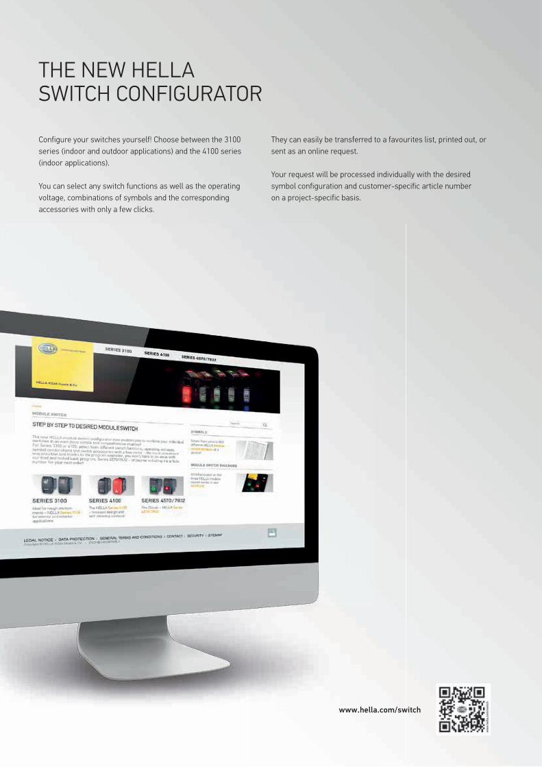
THE NEW HELLA SWITCH CONFIGURATOR
Configure your switches yourself! Choose between the 3100 series (indoor and outdoor applications) and the 4100 series (indoor applications).
You can select any switch functions as well as the operating voltage, combinations of symbols and the corresponding accessories with only a few clicks.
They can easily be transferred to a favourites list, printed out, or sent as an online request.
Your request will be processed individually with the desired symbol configuration and customer-specific article number on a project-specific basis.
www.hella.com/switch

Everything we do revolves around our customers.
In order to ensure that business runs smoothly, HELLA supports wholesalers as your daily business is already complicated enough. That's why we see it as our job to make this as simple as possible for you.
For the aftermarket, we offer outstanding availability of goods using sophisticated logistics and first-class data management as well as targeted sales support. This speeds up and simplifies the wholesale business – for greater efficiency.
We support workshops throughout the entire repair process. We search proactively for new solutions to help independent workshops successfully master the growing complexity of the different models so that customer cars can "hit the road" that much faster. This is how we make your daily business run faster and more profitable.
BUSINESS. SIMPLIFIED.

CONTENT
Series overview 02
3100 series 04
4100 series 10
4570/7832 series 20
Accessories 36
Icon overview 38
| 1

3100 - 4100 - 4570 - / 7832 -
� Waterproof and dustproof module switch series � High level of reliability under extreme conditions � Ideal for use in harsh environments � Individual application due to abrasion-resistant lasered symbols � Wide range of standard and customer-specific symbols
� Self-cleaning contacts � Safe switching of small currents without contaminating the contacts
� Individual application due to abrasion-resistant laser symbols � Wide range of standard and customer-specific symbols � Classic design
� Basic range � Proven over more than 20 years � Individual application due to snap-in lasered symbols � Replacement and retrofitting through standardised mounting hole and mounting frame
Mounting hole, without installation frame [mm] 37,0 x 21,1 41,8 x 19,8 44,1 x 22,1Mounting hole, with installation frame [mm] 51.3 x 48.3 (for two units) 44.1 x 22.1 (for one unit) 51.3 x 48.1 (for two units)Dashboard thickness for direct installation [mm] 1,6...6,3 2 (+/- 0,3) 1…2,5Dashboard thickness with installation frame [mm] 2,5…6,5 3…4 1…2,5
Switch function
Normally open contactChangeover contact
Normally open contact with lockChangeover contact with lockHazard warning flashingWarning light
Normally open contactChangeover contact
Changeover contact with lockHazard warning flashingWarning light
Normally open contactChangeover contactCombination switchNormally open contact with lockChangeover contact with lockHazard warning flashingWarning light
Switch principle Bridge switch Microswitch with self-cleaning contacts Bridge switch
Actuation mode PushbuttonToggle
PushbuttonToggle
PushbuttonToggle
Circuits Max. 2 Max. 2 Max. 2Switching steps 0-1, 0-1-2, 1-0-2 0-1, 0-1-2, 1-0-2 0-1, 0-1-2, 1-0-2Protection class IP 68, connector side: IP 66 IP 52 IP6Rated switching current, resistive load, 12 V [A] 20 10 16Rated switching current, resistive load, 24 V [A] 15 10 8Electrical service life, resistive load, 12 V 50,000 switching cycles, 20 A 50,000 switching cycles, 10 A 20,000 switching cycles, 16 AElectrical service life, resistive load, 24 V 50,000 switching cycles, 15 A 50,000 switching cycles, 10 A 20,000 switching cycles, 8 AMechanical design life 150,000 switching cycles 450,000 switching cycles 250,000 switching cyclesBlade terminal [mm] 6,3 x 0,8 2,8 x 0,8 6,3 x 0,8Operating temperature [°C] -40…+85 -40…+85 -35…+65Housing material PBT PA PA6Rocker switch material PC transparent, painted PC transparent, painted PA6Function check Yes, partially Yes, partially Yes, partiallyLocation lighting Yes Yes YesLight source LED LED LED / BulbType of symbols lasered Lasered Symbol plate, colouredConfigurable online? Yes (www.hella.com/switch) Yes (www.hella.com/switch) No
SERIES OVERVIEW

3100 - 4100 - 4570 - / 7832 -
� Waterproof and dustproof module switch series � High level of reliability under extreme conditions � Ideal for use in harsh environments � Individual application due to abrasion-resistant lasered symbols � Wide range of standard and customer-specific symbols
� Self-cleaning contacts � Safe switching of small currents without contaminating the contacts
� Individual application due to abrasion-resistant laser symbols � Wide range of standard and customer-specific symbols � Classic design
� Basic range � Proven over more than 20 years � Individual application due to snap-in lasered symbols � Replacement and retrofitting through standardised mounting hole and mounting frame
Mounting hole, without installation frame [mm] 37,0 x 21,1 41,8 x 19,8 44,1 x 22,1Mounting hole, with installation frame [mm] 51.3 x 48.3 (for two units) 44.1 x 22.1 (for one unit) 51.3 x 48.1 (for two units)Dashboard thickness for direct installation [mm] 1,6...6,3 2 (+/- 0,3) 1…2,5Dashboard thickness with installation frame [mm] 2,5…6,5 3…4 1…2,5
Switch function
Normally open contactChangeover contact
Normally open contact with lockChangeover contact with lockHazard warning flashingWarning light
Normally open contactChangeover contact
Changeover contact with lockHazard warning flashingWarning light
Normally open contactChangeover contactCombination switchNormally open contact with lockChangeover contact with lockHazard warning flashingWarning light
Switch principle Bridge switch Microswitch with self-cleaning contacts Bridge switch
Actuation mode PushbuttonToggle
PushbuttonToggle
PushbuttonToggle
Circuits Max. 2 Max. 2 Max. 2Switching steps 0-1, 0-1-2, 1-0-2 0-1, 0-1-2, 1-0-2 0-1, 0-1-2, 1-0-2Protection class IP 68, connector side: IP 66 IP 52 IP6Rated switching current, resistive load, 12 V [A] 20 10 16Rated switching current, resistive load, 24 V [A] 15 10 8Electrical service life, resistive load, 12 V 50,000 switching cycles, 20 A 50,000 switching cycles, 10 A 20,000 switching cycles, 16 AElectrical service life, resistive load, 24 V 50,000 switching cycles, 15 A 50,000 switching cycles, 10 A 20,000 switching cycles, 8 AMechanical design life 150,000 switching cycles 450,000 switching cycles 250,000 switching cyclesBlade terminal [mm] 6,3 x 0,8 2,8 x 0,8 6,3 x 0,8Operating temperature [°C] -40…+85 -40…+85 -35…+65Housing material PBT PA PA6Rocker switch material PC transparent, painted PC transparent, painted PA6Function check Yes, partially Yes, partially Yes, partiallyLocation lighting Yes Yes YesLight source LED LED LED / BulbType of symbols lasered Lasered Symbol plate, colouredConfigurable online? Yes (www.hella.com/switch) Yes (www.hella.com/switch) No
| 32

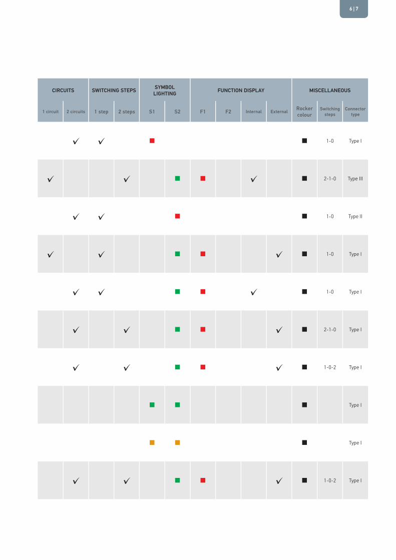
FUNCTION CIRCUIT DIAGRAM DESIGN ACTUATION MODE OPERATING VOLTAGE CIRCUITS SWITCHING STEPS SYMBOL
LIGHTING FUNCTION DISPLAY MISCELLANEOUS
Warning light Switches Switch
with lockHazard light
switch Toggle Pushbutton Volt 1 circuit 2 circuits 1 step 2 steps S1 S2 F1 F2 Internal External Rocker colour
Switching steps
Connector type
00
3-7
+8
0
D2
R2D1
R1
+2
✓ ✓ 12 V / 24 V ✓ ✓ ✓ 1-0 Type I
01
3-7
0
D2
R2
+2
✓ ✓ 12 V / 24 V ✓ ✓ 1-0 Type I
02
3 6-7
+8
D2
R2D1
R1
0
+2 5
✓ ✓ 12 V / 24 V ✓ ✓ ✓ 2-1-0 Type I
03
3 1 6-7
+8
0
D2
R2D1
R1
+2 5
4
✓ ✓ 12 V / 24 V ✓ ✓ ✓ 1-0 Type I
04
3 1 6-7
0
D2
R2
+2 5
4
✓ ✓ 12 V / 24 V ✓ ✓ 1-0 Type I
05
3 1 6-7
+8
0
D2
R2D1
R1
+2 5
4
✓ ✓ 12 V / 24 V ✓ ✓ ✓ 1-0 Type I

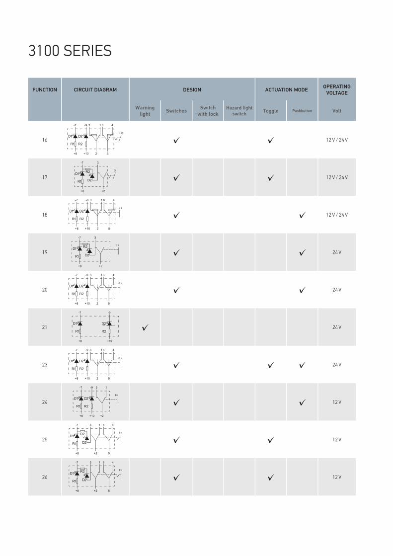
3100 SERIES
The waterproof module switch 3100 series for electrical systems meets the requirements of the protection class IP 68. The lasered symbols are illuminated by integrated LEDs. The series is ideal for use in agricultural and construction vehicles due to its high reliability under extreme conditions. It is also simple to install either directly in the mounting hole or using a modular mounting frame.
FUNCTION CIRCUIT DIAGRAM DESIGN ACTUATION MODE OPERATING VOLTAGE CIRCUITS SWITCHING STEPS SYMBOL
LIGHTING FUNCTION DISPLAY MISCELLANEOUS
Warning light Switches Switch
with lockHazard light
switch Toggle Pushbutton Volt 1 circuit 2 circuits 1 step 2 steps S1 S2 F1 F2 Internal External Rocker colour
Switching steps
Connector type
00
3-7
+8
0
D2
R2D1
R1
+2
✓ ✓ 12 V / 24 V ✓ ✓ ✓ 1-0 Type I
01
3-7
0
D2
R2
+2
✓ ✓ 12 V / 24 V ✓ ✓ 1-0 Type I
02
3 6-7
+8
D2
R2D1
R1
0
+2 5
✓ ✓ 12 V / 24 V ✓ ✓ ✓ 2-1-0 Type I
03
3 1 6-7
+8
0
D2
R2D1
R1
+2 5
4
✓ ✓ 12 V / 24 V ✓ ✓ ✓ 1-0 Type I
04
3 1 6-7
0
D2
R2
+2 5
4
✓ ✓ 12 V / 24 V ✓ ✓ 1-0 Type I
05
3 1 6-7
+8
0
D2
R2D1
R1
+2 5
4
✓ ✓ 12 V / 24 V ✓ ✓ ✓ 1-0 Type I
| 54

3100 SERIES
FUNCTION CIRCUIT DIAGRAM DESIGN ACTUATION MODE OPERATING VOLTAGE CIRCUITS SWITCHING STEPS SYMBOL
LIGHTING FUNCTION DISPLAY MISCELLANEOUS
Warning light Switches Switch
with lockHazard light
switch Toggle Pushbutton Volt 1 circuit 2 circuits 1 step 2 steps S1 S2 F1 F2 Internal External Rocker colour
Switching steps
Connector type
06
3 1 6-7
0
D2
R2
+2 5
4
✓ ✓ 12 V / 24 V ✓ ✓ 1-0 Type I
07
3 +14 11-9
+10
0
D2
R2D1
R1
13
✓ ✓ 12 V / 24 V ✓ ✓ ✓ 2-1-0 Type III
08
317 18 1-10
+8
0D1
R1
+5 2
R1A ✓ ✓ 12 V / 24 V ✓ ✓ 1-0 Type II
09
3 1
0
D2
R2
D1
R1
+2
-7
+8
-9
+10
✓ ✓ 12 V / 24 V ✓ ✓ ✓ 1-0 Type I
10
3 6-7
+8
0
D2
R2D1
R1
+2 5
✓ ✓ 12 V / 24 V ✓ ✓ ✓ 1-0 Type I
11
3 1 6 4
0
D2
R2
D1
R1
-7
+8
-9
+10 2 5
✓ ✓ ✓ 12 V / 24 V ✓ ✓ ✓ 2-1-0 Type I
12
3 1 6 4
0
D2
R2
D1
R1
-7
+8
-9
+10 2 5
✓ ✓ 12 V / 24 V ✓ ✓ ✓ 1-0-2 Type I
13D1
R1
-7
+8
D2
R2
-9
+10
✓ 12 V / 24 V Type I
14D1
R1
-7
+8
D2
R2
-9
+10
✓ 12 V / 24 V Type I
15
3 1 6 4
0
D2
R2
D1
R1
-7
+8
-9
+10 2 5
✓ ✓ 12 V / 24 V ✓ ✓ ✓ 1-0-2 Type I
| 76
FUNCTION CIRCUIT DIAGRAM DESIGN ACTUATION MODE OPERATING VOLTAGE CIRCUITS SWITCHING STEPS SYMBOL
LIGHTING FUNCTION DISPLAY MISCELLANEOUS
Warning light Switches Switch
with lockHazard light
switch Toggle Pushbutton Volt 1 circuit 2 circuits 1 step 2 steps S1 S2 F1 F2 Internal External Rocker colour
Switching steps
Connector type
16
3 1 6 4
0
D2
R2
D1
R1
-7
+8
-9
+10 2 5
✓ ✓ 12 V / 24 V ✓ ✓ ✓ 2-1-0 Type I
17
3-7
+8
0
D2
R2D1
R1
+2
✓ ✓ 12 V / 24 V ✓ ✓ ✓ 1-0 Type I
18
3 1 6 4
0
D2
R2
D1
R1
-7
+8
-9
+10 2 5
✓ ✓ 12 V / 24 V ✓ ✓ ✓ 1-0-2 Type I
19
3-7
+8
0
D2
R2D1
R1
+2
✓ ✓ 24 V ✓ ✓ ✓ 1-0 Type I
20
3 1 6 4
0
D2
R2
D1
R1
-7
+8
-9
+10 2 5
✓ ✓ 24 V ✓ ✓ ✓ 1-0-2 Type I
21D1
R1
-7
+8
D2
R2
-9
+10
✓ 24 V Type I
23
3 1 6 4
0
D2
R2
D1
R1
-7
+8
-9
+10 2 5
✓ ✓ ✓ 24 V ✓ ✓ ✓ 1-0-2 Type I
24
3 1
0
D2
R2
D1
R1
+2
-7
+8
-9
+10
✓ ✓ 12 V ✓ ✓ ✓ 1-0 Type I
25
3 1 6-7
+8
0
D2
R2D1
R1
+2 5
4
✓ ✓ 12 V ✓ ✓ ✓ 1-0 Type I
26
3 1 6-7
+8
0
D2
R2D1
R1
+2 5
4
✓ ✓ 12 V ✓ ✓ ✓ 1-0 Type I
3100 SERIES

FUNCTION CIRCUIT DIAGRAM DESIGN ACTUATION MODE OPERATING VOLTAGE CIRCUITS SWITCHING STEPS SYMBOL
LIGHTING FUNCTION DISPLAY MISCELLANEOUS
Warning light Switches Switch
with lockHazard light
switch Toggle Pushbutton Volt 1 circuit 2 circuits 1 step 2 steps S1 S2 F1 F2 Internal External Rocker colour
Switching steps
Connector type
16
3 1 6 4
0
D2
R2
D1
R1
-7
+8
-9
+10 2 5
✓ ✓ 12 V / 24 V ✓ ✓ ✓ 2-1-0 Type I
17
3-7
+8
0
D2
R2D1
R1
+2
✓ ✓ 12 V / 24 V ✓ ✓ ✓ 1-0 Type I
18
3 1 6 4
0
D2
R2
D1
R1
-7
+8
-9
+10 2 5
✓ ✓ 12 V / 24 V ✓ ✓ ✓ 1-0-2 Type I
19
3-7
+8
0
D2
R2D1
R1
+2
✓ ✓ 24 V ✓ ✓ ✓ 1-0 Type I
20
3 1 6 4
0
D2
R2
D1
R1
-7
+8
-9
+10 2 5
✓ ✓ 24 V ✓ ✓ ✓ 1-0-2 Type I
21D1
R1
-7
+8
D2
R2
-9
+10
✓ 24 V Type I
23
3 1 6 4
0
D2
R2
D1
R1
-7
+8
-9
+10 2 5
✓ ✓ ✓ 24 V ✓ ✓ ✓ 1-0-2 Type I
24
3 1
0
D2
R2
D1
R1
+2
-7
+8
-9
+10
✓ ✓ 12 V ✓ ✓ ✓ 1-0 Type I
25
3 1 6-7
+8
0
D2
R2D1
R1
+2 5
4
✓ ✓ 12 V ✓ ✓ ✓ 1-0 Type I
26
3 1 6-7
+8
0
D2
R2D1
R1
+2 5
4
✓ ✓ 12 V ✓ ✓ ✓ 1-0 Type I
| 98

FUNCTION CIRCUIT DIAGRAM DESIGN ACTUATION MODE OPERATING VOLTAGE CIRCUITS SWITCHING STEPS SYMBOL
LIGHTING FUNCTION DISPLAY MISCELLANEOUS
Warning light Switches Switch
with lockHazard light
switch Toggle Pushbutton Volt 1 circuit 2 circuits 1 step 2 steps S1 S2 F1 F2 Internal External Rocker colour Switching steps
00
5 3 1
7 10
SB0
✓ ✓ 12 V / 24 V ✓ ✓ 0-1
01
5 3 1
7 10
SB0
FA
✓ ✓ 12 V / 24 V ✓ ✓ ✓ 0-1
02
5 3 1
7 10
SB0
FA
✓ ✓ 12 V / 24 V ✓ ✓ ✓ 0-1
03
5 3 6 18
7 10
SB0
4
✓ ✓ 12 V / 24 V ✓ ✓ 0-1
04
5 3 6 18
7 10
SB0
4FA
✓ ✓ 12 V / 24 V ✓ ✓ ✓ 0-1
05
5 3 1
7 10
SB0
FA
68
4
✓ ✓ 12 V / 24 V ✓ ✓ ✓ 0-1

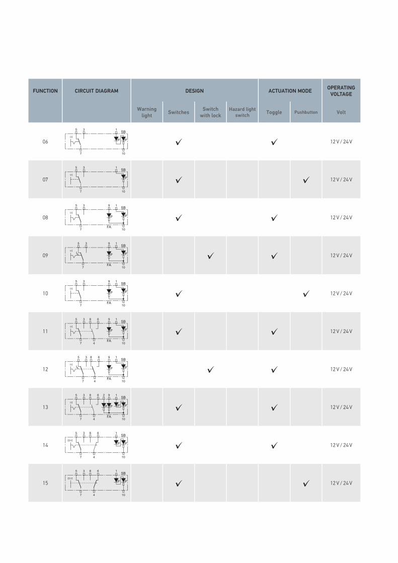
4100 SERIES
The modular switch series with a self-cleaning microswitch is suitable for modern electrical and electronic systems. This also ensures reliable switching of small currents without contaminating the contacts. The series features a timeless design, with lasered symbols illuminated by integrated LEDs.
FUNCTION CIRCUIT DIAGRAM DESIGN ACTUATION MODE OPERATING VOLTAGE CIRCUITS SWITCHING STEPS SYMBOL
LIGHTING FUNCTION DISPLAY MISCELLANEOUS
Warning light Switches Switch
with lockHazard light
switch Toggle Pushbutton Volt 1 circuit 2 circuits 1 step 2 steps S1 S2 F1 F2 Internal External Rocker colour Switching steps
00
5 3 1
7 10
SB0
✓ ✓ 12 V / 24 V ✓ ✓ 0-1
01
5 3 1
7 10
SB0
FA
✓ ✓ 12 V / 24 V ✓ ✓ ✓ 0-1
02
5 3 1
7 10
SB0
FA
✓ ✓ 12 V / 24 V ✓ ✓ ✓ 0-1
03
5 3 6 18
7 10
SB0
4
✓ ✓ 12 V / 24 V ✓ ✓ 0-1
04
5 3 6 18
7 10
SB0
4FA
✓ ✓ 12 V / 24 V ✓ ✓ ✓ 0-1
05
5 3 1
7 10
SB0
FA
68
4
✓ ✓ 12 V / 24 V ✓ ✓ ✓ 0-1
| 1110
FUNCTION CIRCUIT DIAGRAM DESIGN ACTUATION MODE OPERATING VOLTAGE CIRCUITS SWITCHING STEPS SYMBOL
LIGHTING FUNCTION DISPLAY MISCELLANEOUS
Warning light Switches Switch
with lockHazard light
switch Toggle Pushbutton Volt 1 circuit 2 circuits 1 step 2 steps S1 S2 F1 F2 Internal External Rocker colour Switching steps
06
5 3 1
7 10
SB0
✓ ✓ 12 V / 24 V ✓ ✓ 0-1
07
5 3 1
7 10
SB0
✓ ✓ 12 V / 24 V ✓ ✓ 0-1
08
5 3 19
7 10
SB0
FA
✓ ✓ 12 V / 24 V ✓ ✓ ✓ 0-1
09
1
10
SB95 3
7
0
FA
✓ ✓ 12 V / 24 V ✓ ✓ ✓ 0-1
10
5 3 19
7 10
SB0
FA
✓ ✓ 12 V / 24 V ✓ ✓ ✓ 0-1
11
5 3 6 18
7 10
SB0
4FA
9
✓ ✓ 12 V / 24 V ✓ ✓ ✓ 0-1
12
5 3 1
7 10
SB0
FA
68
4
9
✓ ✓ 12 V / 24 V ✓ ✓ ✓ 0-1
13
5 3 6 18
7 10
SB0
4FA
92
✓ ✓ 12 V / 24 V ✓ ✓ ✓ 0-1
14
5 3 6 18
7 10
SB0
4
✓ ✓ 12 V / 24 V ✓ ✓ 2-0-1
15
5 3 6 18
7 10
SB0
4
✓ ✓ 12 V / 24 V ✓ ✓ 2-0-1
| 1312

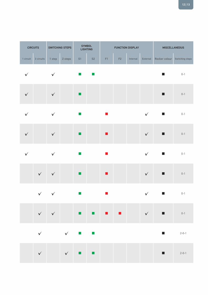
FUNCTION CIRCUIT DIAGRAM DESIGN ACTUATION MODE OPERATING VOLTAGE CIRCUITS SWITCHING STEPS SYMBOL
LIGHTING FUNCTION DISPLAY MISCELLANEOUS
Warning light Switches Switch
with lockHazard light
switch Toggle Pushbutton Volt 1 circuit 2 circuits 1 step 2 steps S1 S2 F1 F2 Internal External Rocker colour Switching steps
16
5 3 6 18
7 10
SB0
4
✓ ✓ 12 V / 24 V ✓ ✓ ✓ 2-0-1
17
5 3 6 18
7 10
SB0
4FA
9
✓ ✓ 12 V / 24 V ✓ ✓ ✓ 2-0-1
18
5 3 6 18
7 10
SB0
4FA
✓ ✓ 12 V / 24 V ✓ ✓ ✓ 2-0-1
19
5 3 6 18
7 10
SB0
4
✓ ✓ 12 V / 24 V ✓ ✓ 2-0-1
20
5 3 6 18
7 10
SB0
4FA
9
✓ ✓ ✓ 12 V / 24 V ✓ ✓ ✓ 2-0-1
21
5 3 6 18
7 10
SB
4FA
92
0
✓ ✓ 12 V / 24 V ✓ ✓ ✓ 2-0-1
22
5 3 6 18
7 10
SB
4FA
92
0
✓ ✓ 12 V / 24 V ✓ ✓ ✓ 2-0-1
23
5 3 6 18
7 10
SB
4FA
9
0
✓ ✓ 12 V / 24 V ✓ ✓ ✓ 2-0-1
24
3 1
7 10
SB0
6
4
✓ ✓ 12 V / 24 V ✓ ✓ 0-1-2
25
1
10
SB3
7 4
0
FA
✓ ✓ 12 V / 24 V ✓ ✓ ✓ 0-1
| 1514
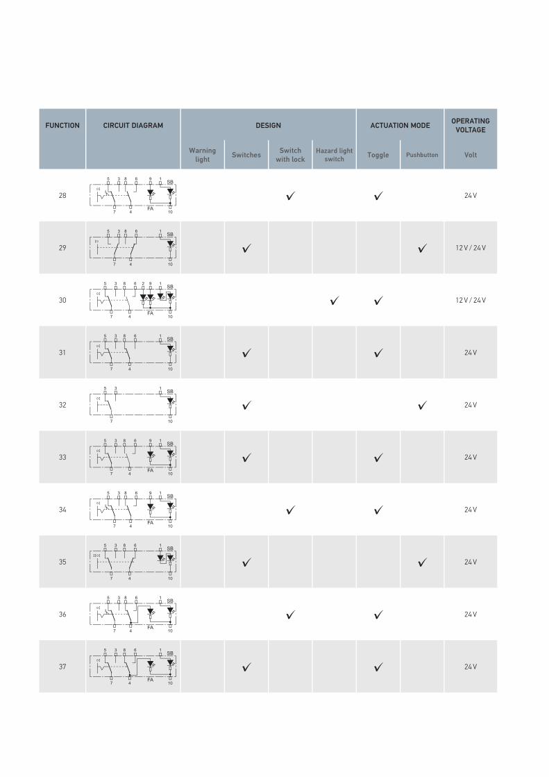
FUNCTION CIRCUIT DIAGRAM DESIGN ACTUATION MODE OPERATING VOLTAGE CIRCUITS SWITCHING STEPS SYMBOL
LIGHTING FUNCTION DISPLAY MISCELLANEOUS
Warning light Switches Switch
with lockHazard light
switch Toggle Pushbutton Volt 1 circuit 2 circuits 1 step 2 steps S1 S2 F1 F2 Internal External Rocker colour Switching steps
28
5 3 1
7 10
SB0
FA
68
4
9
✓ ✓ 24 V ✓ ✓ ✓ 0-1
29
5 3 1
7 10
SB0
68
4
✓ ✓ 12 V / 24 V ✓ ✓ 0-1
30
5 3 6 18
7 10
SB0
4FA
92
✓ ✓ 12 V / 24 V ✓ ✓ ✓ 0-1
31
5 3 6 18
7 10
SB0
4
✓ ✓ 24 V ✓ ✓ 0-1
32
5 3 1
7 10
SB0
✓ ✓ 24 V ✓ ✓ 0-1
33
5 3 6 18
7 10
SB0
4FA
9
✓ ✓ 24 V ✓ ✓ ✓ 0-1
34
5 3 1
7 10
SB0
FA
68
4
9
✓ ✓ 24 V ✓ ✓ ✓ 0-1
35
5 3 6 18
7 10
SB0
4
✓ ✓ 24 V ✓ ✓ 2-0-1
36
5 3 1
7 10
SB0
FA
68
4
✓ ✓ 24 V ✓ ✓ ✓ 0-1
37
5 3 6 18
7 10
SB0
4FA
✓ ✓ 24 V ✓ ✓ ✓ 0-1
| 1716
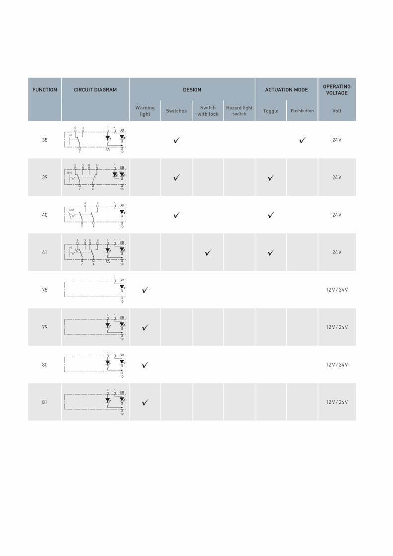
FUNCTION CIRCUIT DIAGRAM DESIGN ACTUATION MODE OPERATING VOLTAGE CIRCUITS SWITCHING STEPS SYMBOL
LIGHTING FUNCTION DISPLAY MISCELLANEOUS
Warning light Switches Switch
with lockHazard light
switch Toggle Pushbutton Volt 1 circuit 2 circuits 1 step 2 steps S1 S2 F1 F2 Internal External Rocker colour Switching steps
38
5 3 19
7 10
SB0
FA
✓ ✓ 24 V ✓ ✓ ✓ 0-1
39
5 3 6 18
7 10
SB0
4
✓ ✓ 24 V ✓ ✓ 2-0-1
40
3 1
7 10
SB0
6
4
✓ ✓ 24 V ✓ ✓ 0-1-2
41
5 3 1
7 10
SB0
FA
68
4
9
✓ ✓ 24 V ✓ ✓ ✓ 0-1
78
1
10
SB
✓ 12 V / 24 V
79
1
10
SB4
✓ 12 V / 24 V
80
1
10
SB4
✓ 12 V / 24 V
81
1
10
SB4
✓ 12 V / 24 V
| 1918

CIRCUIT DIAGRAM SERIES PART NO. DESIGN ACTUATION MODE OPERATING VOLTAGE CIRCUITS SWITCHING STEPS LIGHTING TYPE MISCELLANEOUS
4570 7832 Switches Switch with lock
Hazard light switch Toggle Pushbutton Volt 1 circuit 2 circuits 1 step 2 steps Without
lightingLocation lighting
With pilot lighting and function lighting
Rocker colour
Switching steps
gold-plated connections
✓ 6EH 004 570-001 ✓ ✓ 12-32 V ✓ ✓ ✓ I-0
✓ 6EH 007 832-001 ✓ ✓ 12-32 V ✓ ✓ ✓ I-0
✓ 6FH 004 570-101 ✓ ✓ 12-32 V ✓ ✓ ✓ I-0
✓ 6FH 007 832-051 ✓ ✓ 12-32 V ✓ ✓ ✓ I-0
✓ 6EH 004 570-011 ✓ ✓ 12-32 V ✓ ✓ ✓ I-0
✓ 6EH 007 832-011 ✓ ✓ 12-32 V ✓ ✓ ✓ I-0
✓ 6FH 004 570-111 ✓ ✓ 12-32 V ✓ ✓ ✓ I-0
✓ 6FH 007 832-061 ✓ ✓ 12-32 V ✓ ✓ ✓ I-0
✓ 6EH 004 570-021 ✓ ✓ 12-32 V ✓ ✓ ✓ I-0
✓ 6EH 004 570-027 ✓ ✓ 12-32 V ✓ ✓ ✓ I-0
✓ 6EH 007 832-021 ✓ ✓ 12-32 V ✓ ✓ ✓ I-0
✓ 6FH 004 570-777 ✓ ✓ 12-32 V ✓ ✓ ✓ I-0 ✓✓ 6FH 004 570-121 ✓ ✓ 12-32 V ✓ ✓ ✓ I-0
✓ 6FH 004 570-127 ✓ ✓ 12-32 V ✓ ✓ ✓ I-0
✓ 6FH 007 832-081 ✓ ✓ 12-32 V ✓ ✓ ✓ I-0

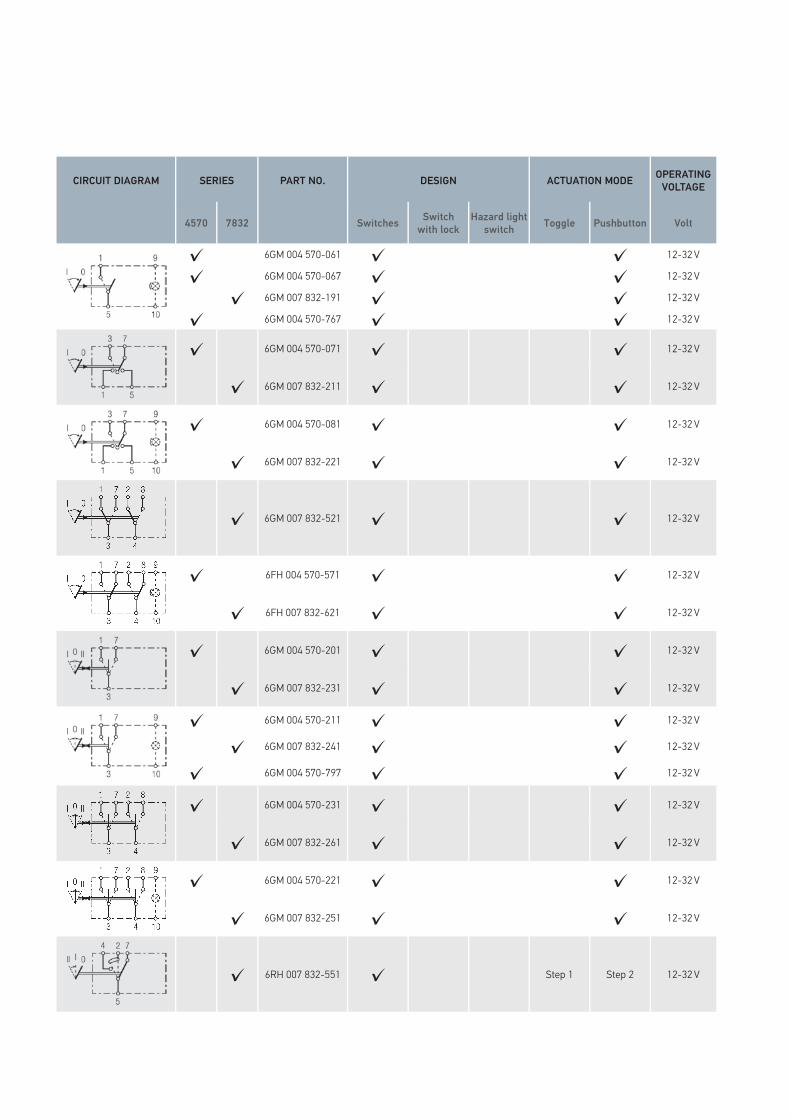
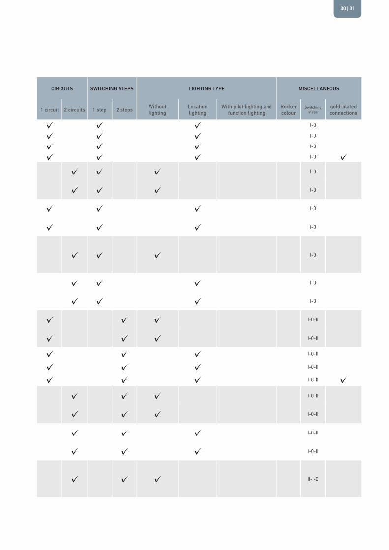
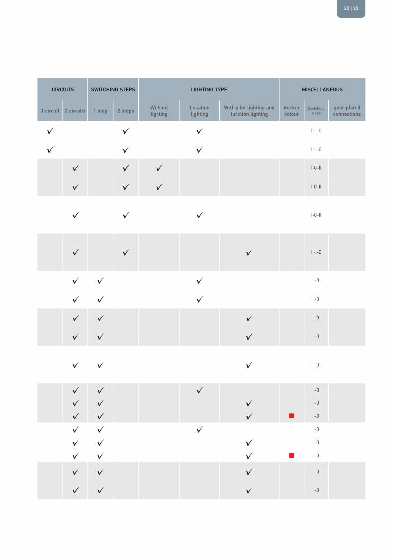
4570/7832 SERIES
The basic program for simple electrical systems that has proven itself over more than 20 years. The symbol cards are available to DIN standard or in the customer’s choice of colours. The symbols are lit by incandescent bulbs or LEDs, which can be ordered as accessories.
CIRCUIT DIAGRAM SERIES PART NO. DESIGN ACTUATION MODE OPERATING VOLTAGE CIRCUITS SWITCHING STEPS LIGHTING TYPE MISCELLANEOUS
4570 7832 Switches Switch with lock
Hazard light switch Toggle Pushbutton Volt 1 circuit 2 circuits 1 step 2 steps Without
lightingLocation lighting
With pilot lighting and function lighting
Rocker colour
Switching steps
gold-plated connections
✓ 6EH 004 570-001 ✓ ✓ 12-32 V ✓ ✓ ✓ I-0
✓ 6EH 007 832-001 ✓ ✓ 12-32 V ✓ ✓ ✓ I-0
✓ 6FH 004 570-101 ✓ ✓ 12-32 V ✓ ✓ ✓ I-0
✓ 6FH 007 832-051 ✓ ✓ 12-32 V ✓ ✓ ✓ I-0
✓ 6EH 004 570-011 ✓ ✓ 12-32 V ✓ ✓ ✓ I-0
✓ 6EH 007 832-011 ✓ ✓ 12-32 V ✓ ✓ ✓ I-0
✓ 6FH 004 570-111 ✓ ✓ 12-32 V ✓ ✓ ✓ I-0
✓ 6FH 007 832-061 ✓ ✓ 12-32 V ✓ ✓ ✓ I-0
✓ 6EH 004 570-021 ✓ ✓ 12-32 V ✓ ✓ ✓ I-0
✓ 6EH 004 570-027 ✓ ✓ 12-32 V ✓ ✓ ✓ I-0
✓ 6EH 007 832-021 ✓ ✓ 12-32 V ✓ ✓ ✓ I-0
✓ 6FH 004 570-777 ✓ ✓ 12-32 V ✓ ✓ ✓ I-0 ✓✓ 6FH 004 570-121 ✓ ✓ 12-32 V ✓ ✓ ✓ I-0
✓ 6FH 004 570-127 ✓ ✓ 12-32 V ✓ ✓ ✓ I-0
✓ 6FH 007 832-081 ✓ ✓ 12-32 V ✓ ✓ ✓ I-0
| 2120

CIRCUIT DIAGRAM SERIES PART NO. DESIGN ACTUATION MODE OPERATING VOLTAGE CIRCUITS SWITCHING STEPS LIGHTING TYPE MISCELLANEOUS
4570 7832 Switches Switch with lock
Hazard light switch Toggle Pushbutton Volt 1 circuit 2 circuits 1 step 2 steps Without
lightingLocation lighting
With pilot lighting and function lighting
Rocker colour
Switching steps
gold-plated connections
✓ 6EH 004 570-621 ✓ ✓ 12-32 V ✓ ✓ ✓ I-0
✓ 6EH 007 832-041 ✓ ✓ 12-32 V ✓ ✓ ✓ I-0
✓ 6EH 004 570-681 ✓ ✓ 12-32 V ✓ ✓ ✓ I-0
✓ 6EH 007 832-611 ✓ ✓ 12-32 V ✓ ✓ ✓ I-0
✓ 6FH 004 570-501 ✓ ✓ 12-32 V ✓ ✓ ✓ I-0
✓ 6FH 007 832-121 ✓ ✓ 12-32 V ✓ ✓ ✓ I-0
✓ 6EH 007 832-601 ✓(2) ✓ 12-32 V ✓ ✓ ✓ I-0
✓ 6FH 004 570-341 ✓ ✓ 12-32 V ✓ ✓ ✓ I-0
✓ 6EH 004 570-641 ✓(2) ✓ 12-32 V ✓ ✓ ✓ I-0
✓ 6EH 007 832-751 ✓(2) ✓ 12-32 V ✓ ✓ ✓ I-0
✓ 6FH 004 570-131 ✓ ✓ 12-32 V ✓ ✓ ✓ I-0
✓ 6FH 004 570-137 ✓ ✓ 12-32 V ✓ ✓ ✓ I-0
✓ 6FH 007 832-101 ✓ ✓ 12-32 V ✓ ✓ ✓ I-0
✓ 6RH 008 948-012 ✓ ✓ 12-32 V ✓ ✓ ✓ I-0
✓ 6RH 008 910-011 ✓ ✓ 12-32 V ✓ ✓ ✓ I-0 ✓
✓ 6EH 007 832-491 ✓ ✓ 12-32 V ✓ ✓ ✓ I-0
| 2322

CIRCUIT DIAGRAM SERIES PART NO. DESIGN ACTUATION MODE OPERATING VOLTAGE CIRCUITS SWITCHING STEPS LIGHTING TYPE MISCELLANEOUS
4570 7832 Switches Switch with lock
Hazard light switch Toggle Pushbutton Volt 1 circuit 2 circuits 1 step 2 steps Without
lightingLocation lighting
With pilot lighting and function lighting
Rocker colour
Switching steps
gold-plated connections
✓ 6EH 007 832-671 ✓(2) ✓ 12-32 V ✓ ✓ ✓ I-0
✓ 6FH 004 570-511 ✓ ✓ 12-32 V ✓ ✓ ✓ II-0-I
✓ 6FH 004 570-517 ✓ ✓ 12-32 V ✓ ✓ ✓ II-0-I
✓ 6FH 007 832-131 ✓ ✓ 12-32 V ✓ ✓ ✓ II-0-I
✓ 6RH 004 570-151 ✓ ✓ 12-32 V ✓ ✓ ✓ II-I-0
✓ 6RH 007 832-331 ✓ ✓ 12-32 V ✓ ✓ ✓ II-I-0
✓ 6RH 004 570-161 ✓ ✓ 12-32 V ✓ ✓ ✓ II-I-0
✓ 6RH 007 832-341 ✓ ✓ 12-32 V ✓ ✓ ✓ II-I-0
✓ 6RH 004 570-171 ✓ ✓ 12-32 V ✓ ✓ ✓ II-I-0
✓ 6RH 004 570-177 ✓ ✓ 12-32 V ✓ ✓ ✓ II-I-0
✓ 6RH 007 832-351 ✓ ✓ 12-32 V ✓ ✓ ✓ II-I-0
✓ 6RH 004 570-351 ✓ ✓ 12-32 V ✓ ✓ ✓ II-I-0
✓ 6RH 007 832-431 ✓ ✓ 12-32 V ✓ ✓ ✓ II-I-0
✓ 6RH 004 570-311 ✓ Step 1 Step 2 12-32 V ✓ ✓ ✓ II-I-0
✓ 6RH 007 832-411 ✓ Step 1 Step 2 12-32 V ✓ ✓ ✓ II-I-0
✓ 6RH 004 570-361 ✓ ✓ 12-32 V ✓ ✓ ✓ II-I-0
✓ 6RH 007 832-441 ✓ ✓ 12-32 V ✓ ✓ ✓ II-I-0
✓ 6RH 004 570-261 ✓ ✓ 12-32 V ✓ ✓ ✓ II-I-0
✓ 6RH 004 570-267 ✓ ✓ 12-32 V ✓ ✓ ✓ II-I-0
✓ 6RH 007 832-391 ✓ ✓ 12-32 V ✓ ✓ ✓ II-I-0
✓ 6FH 007 832-511 ✓ ✓ 12-32 V ✓ ✓ ✓ II-I-0
| 2524

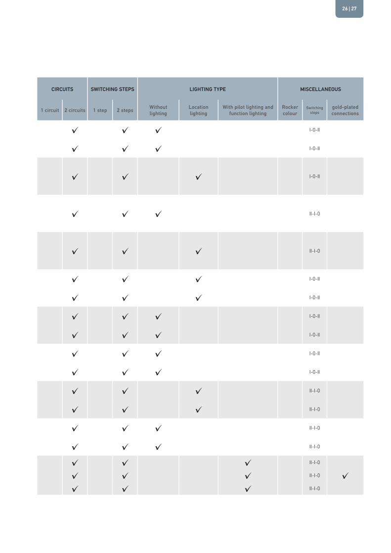
CIRCUIT DIAGRAM SERIES PART NO. DESIGN ACTUATION MODE OPERATING VOLTAGE CIRCUITS SWITCHING STEPS LIGHTING TYPE MISCELLANEOUS
4570 7832 Switches Switch with lock
Hazard light switch Toggle Pushbutton Volt 1 circuit 2 circuits 1 step 2 steps Without
lightingLocation lighting
With pilot lighting and function lighting
Rocker colour
Switching steps
gold-plated connections
✓ 6FH 004 570-531 ✓ ✓ 12-32 V ✓ ✓ ✓ I-0-II
✓ 6FH 007 832-161 ✓ ✓ 12-32 V ✓ ✓ ✓ I-0-II
✓ 6RH 008 948-022 ✓ Step 2 Step 1 12-32 V ✓ ✓ ✓ I-0-II
✓ 6RH 007 832-761 ✓ ✓ 12-32 V ✓ ✓ ✓ II-I-0
✓ 6RH 007 832-681 ✓ ✓ 12-32 V ✓ ✓ ✓ II-I-0
✓ 6FH 004 570-521 ✓ ✓ 12-32 V ✓ ✓ ✓ I-0-II
✓ 6FH 007 832-151 ✓ ✓ 12-32 V ✓ ✓ ✓ I-0-II
✓ 6RH 004 570-751 ✓ ✓ 12-32 V ✓ ✓ ✓ I-0-II
✓ 6RH 007 832-481 ✓ ✓ 12-32 V ✓ ✓ ✓ I-0-II
✓ 6FH 004 570-541 ✓ Step 2 Step 1 12-32 V ✓ ✓ ✓ I-0-II
✓ 6FH 007 832-171 ✓ Step 2 Step 1 12-32 V ✓ ✓ ✓ I-0-II
✓ 6RH 004 570-371 ✓ ✓ 12-32 V ✓ ✓ ✓ II-I-0
✓ 6RH 007 832-701 ✓ ✓ 12-32 V ✓ ✓ ✓ II-I-0
✓ 6RH 004 570-401 ✓ ✓ 12-32 V ✓ ✓ ✓ II-I-0
✓ 6RH 007 832-451 ✓ ✓ 12-32 V ✓ ✓ ✓ II-I-0
✓ 6RH 004 570-187 ✓ ✓ 12-32 V ✓ ✓ ✓ II-I-0
✓ 6RH 004 570-787 ✓ ✓ 12-32 V ✓ ✓ ✓ II-I-0 ✓✓ 6RH 007 832-377 ✓ ✓ 12-32 V ✓ ✓ ✓ II-I-0
| 2726

CIRCUIT DIAGRAM SERIES PART NO. DESIGN ACTUATION MODE OPERATING VOLTAGE CIRCUITS SWITCHING STEPS LIGHTING TYPE MISCELLANEOUS
4570 7832 Switches Switch with lock
Hazard light switch Toggle Pushbutton Volt 1 circuit 2 circuits 1 step 2 steps Without
lightingLocation lighting
With pilot lighting and function lighting
Rocker colour
Switching steps
gold-plated connections
✓ 6RH 004 570-411 ✓ ✓ 12-32 V ✓ ✓ ✓ II-I-0
✓ 6RH 004 570-417 ✓ ✓ 12-32 V ✓ ✓ ✓ II-I-0
✓ 6RH 007 832-461 ✓ ✓ 12-32 V ✓ ✓ ✓ II-I-0
✓ 6RH 004 570-191 ✓ ✓ 12-32 V ✓ ✓ ✓ II-I-0
✓ 6RH 007 832-381 ✓ ✓ 12-32 V ✓ ✓ ✓ II-I-0
✓ 6RH 004 570-321 ✓ ✓ 12-32 V ✓ ✓ ✓ II-I-0
✓ 6RH 007 832-731 ✓ ✓ 12-32 V ✓ ✓ ✓ II-I-0
✓ 6RH 008 910-022 ✓ ✓ 12-32 V ✓ ✓ ✓ II-I-0
✓ 6RH 004 570-671 ✓ ✓ 12-32 V ✓ ✓ ✓ II-I-0
✓ 6RH 004 570-041 ✓ ✓ 12-32 V ✓ ✓ ✓ II-I-0
✓ 6RH 007 832-741 ✓ ✓ 12-32 V ✓ ✓ ✓ II-I-0
✓ 6RH 008 910-032 ✓ ✓ 12-32 V ✓ ✓ ✓ II-I-0
✓ 6RH 007 832-797 ✓ ✓ 12-32 V ✓ ✓ ✓ II-I-0
✓ 6GM 004 570-051 ✓ ✓ 12-32 V ✓ ✓ ✓ I-0
✓ 6GM 007 832-181 ✓ ✓ 12-32 V ✓ ✓ ✓ I-0
✓ 6GM 004 570-691 ✓ ✓ ✓ 12-32 V ✓ ✓ ✓ I-0
✓ 6GM 007 832-271 ✓ ✓ 12-32 V ✓ ✓ ✓ I-0
| 2928
CIRCUIT DIAGRAM SERIES PART NO. DESIGN ACTUATION MODE OPERATING VOLTAGE CIRCUITS SWITCHING STEPS LIGHTING TYPE MISCELLANEOUS
4570 7832 Switches Switch with lock
Hazard light switch Toggle Pushbutton Volt 1 circuit 2 circuits 1 step 2 steps Without
lightingLocation lighting
With pilot lighting and function lighting
Rocker colour
Switching steps
gold-plated connections
✓ 6GM 004 570-061 ✓ ✓ 12-32 V ✓ ✓ ✓ I-0
✓ 6GM 004 570-067 ✓ ✓ 12-32 V ✓ ✓ ✓ I-0
✓ 6GM 007 832-191 ✓ ✓ 12-32 V ✓ ✓ ✓ I-0
✓ 6GM 004 570-767 ✓ ✓ 12-32 V ✓ ✓ ✓ I-0 ✓✓ 6GM 004 570-071 ✓ ✓ 12-32 V ✓ ✓ ✓ I-0
✓ 6GM 007 832-211 ✓ ✓ 12-32 V ✓ ✓ ✓ I-0
✓ 6GM 004 570-081 ✓ ✓ 12-32 V ✓ ✓ ✓ I-0
✓ 6GM 007 832-221 ✓ ✓ 12-32 V ✓ ✓ ✓ I-0
✓ 6GM 007 832-521 ✓ ✓ 12-32 V ✓ ✓ ✓ I-0
✓ 6FH 004 570-571 ✓ ✓ 12-32 V ✓ ✓ ✓ I-0
✓ 6FH 007 832-621 ✓ ✓ 12-32 V ✓ ✓ ✓ I-0
✓ 6GM 004 570-201 ✓ ✓ 12-32 V ✓ ✓ ✓ I-0-II
✓ 6GM 007 832-231 ✓ ✓ 12-32 V ✓ ✓ ✓ I-0-II
✓ 6GM 004 570-211 ✓ ✓ 12-32 V ✓ ✓ ✓ I-0-II
✓ 6GM 007 832-241 ✓ ✓ 12-32 V ✓ ✓ ✓ I-0-II
✓ 6GM 004 570-797 ✓ ✓ 12-32 V ✓ ✓ ✓ I-0-II ✓
✓ 6GM 004 570-231 ✓ ✓ 12-32 V ✓ ✓ ✓ I-0-II
✓ 6GM 007 832-261 ✓ ✓ 12-32 V ✓ ✓ ✓ I-0-II
✓ 6GM 004 570-221 ✓ ✓ 12-32 V ✓ ✓ ✓ I-0-II
✓ 6GM 007 832-251 ✓ ✓ 12-32 V ✓ ✓ ✓ I-0-II
✓ 6RH 007 832-551 ✓ Step 1 Step 2 12-32 V ✓ ✓ ✓ II-I-0
| 3130

CIRCUIT DIAGRAM SERIES PART NO. DESIGN ACTUATION MODE OPERATING VOLTAGE CIRCUITS SWITCHING STEPS LIGHTING TYPE MISCELLANEOUS
4570 7832 Switches Switch with lock
Hazard light switch Toggle Pushbutton Volt 1 circuit 2 circuits 1 step 2 steps Without
lightingLocation lighting
With pilot lighting and function lighting
Rocker colour
Switching steps
gold-plated connections
✓ 6RH 004 570-331 ✓ Step 1 Step 2 12-32 V ✓ ✓ ✓ II-I-0
✓ 6RH 007 832-421 ✓ Step 1 Step 2 12-32 V ✓ ✓ ✓ II-I-0
✓ 6GM 004 570-271 ✓ ✓ 12-32 V ✓ ✓ ✓ I-0-II
✓ 6GM 007 832-631 ✓ ✓ 12-32 V ✓ ✓ ✓ I-0-II
✓ 6FH 004 570-241 ✓ Step 2 Step 1 12-32 V ✓ ✓ ✓ I-0-II
✓ 6RH 007 832-651 ✓(2) Step 1 Step 2 12-32 V ✓ ✓ ✓ II-I-0
✓ 6HH 004 570-431 ✓ ✓ LED 12-32 V ✓ ✓ ✓ I-0
✓ 6HH 007 832-711 ✓ ✓ LED 12-32 V ✓ ✓ ✓ I-0
✓ 6HH 004 570-481 ✓ ✓ 24 V ✓ ✓ ✓ I-0
✓ 6HH 007 832-301 ✓ ✓ 24 V ✓ ✓ ✓ I-0
✓ 6HH 007 832-721 ✓ ✓ LED 12-32 V ✓ ✓ ✓ I-0
✓ 6HH 004 570-491 ✓ ✓ 12 V ✓ ✓ ✓ I-0
✓ 6HH 007 832-321 ✓ ✓ 12 V ✓ ✓ ✓ I-0
✓ 6HH 007 832-807 ✓ ✓ 12 V ✓ ✓ ✓ I-0
✓ 6HH 004 570-451 ✓ ✓ 12 V ✓ ✓ ✓ I-0
✓ 6HH 007 832-281 ✓ ✓ 12 V ✓ ✓ ✓ I-0
✓ 6HH 007 832-661 ✓ ✓ 12 V ✓ ✓ ✓ I-0
✓ 6HH 004 570-477 ✓ ✓ 24 V ✓ ✓ ✓ I-0
✓ 6HH 007 832-297 ✓ ✓ 24 V ✓ ✓ ✓ I-0
| 3332

CIRCUIT DIAGRAM SERIES PART NO. DESIGN ACTUATION MODE OPERATING VOLTAGE CIRCUITS SWITCHING STEPS LIGHTING TYPE MISCELLANEOUS
4570 7832 Switches Switch with lock
Hazard light switch Toggle Pushbutton Volt 1 circuit 2 circuits 1 step 2 steps Without
lightingLocation lighting
With pilot lighting and function lighting
Rocker colour
Switching steps
gold-plated connections
✓ 6HH 004 570-591 ✓ ✓ 24 V ✓ ✓ ✓ I-0
✓ 6HH 007 832-641 ✓ ✓ 24 V ✓ ✓ ✓ I-0
✓ 6HH 007 832-771 ✓ ✓ 12 V ✓ ✓ ✓ I-0
✓ 6HH 007 832-591 ✓ ✓ 24 V ✓ ✓ ✓ I-0
| 3534

VPE = Packaging unit
ACCESSORIES
3100¡ 4100¡ 4570¡ / 7832¡
Part No. VPE Part No. VPE Part No. VPE
MOUNTING STRIPFor 6 switches 8HG 713 626-001 12For 3 switches 8HG 714 504-001 24
INSTALLATION FRAME INSERTION SYSTEM
Single frame 9AR 168 396-0029AR 168 396-007
10200
End piece 8HG 716 734-0018HG 716 734-007
10200
End piece, left 9AR 169 209-1029AR 169 209-107
10100
9AR 169 209-0029AR 169 209-007
10100
Intermediate piece 9AR 169 208-1029AR 169 208-107
10200
9AR 169 208-0029AR 169 208-007
10200
End piece, right 9AR 169 209-1029AR 169 209-107
10100
9AR 169 210-0029AR 169 210-007
10200
DUMMY COVER 9HB 172 229-1019HB 172 229-107
110
9HB 172 229-0029HB 172 229-007
1052 9HB 713 629-001 10
FEMALE CONNECTOR HOUSING
8-pole 8JA 713 631-0018JA 713 631-007
101000
2-pole 8JA 715 600-001 10
10-pin 8JD 010 076-0028JD 010 076-007
10440
10-pin, type 1 8JD 010 076-1028JD 010 076-107
1050
10-pin, type 2 8JD 010 076-1128JD 010 076-117
1050
10-pin, type 3 8JD 010 076-1228JD 010 076-127
1050
FLAT RECEPTACLE CUSN/SN / JUNIOR POWER TIMERFor cable cross-section 0.5 mm² – 1.0 mm² 8KW 744 882-003 100 8KW 863 934-003 50
For cable cross-section 1.0 – 2.5 mm² 8KW 744 825-003 100 8KW 863 934-0238KW 863 934-003
501000
DISASSEMBLY 8PE 197 631-001 1
VPE = Packaging unit
3100¡ 4100¡ 4570¡ / 7832¡
Part No. VPE Part No. VPE Part No. VPE
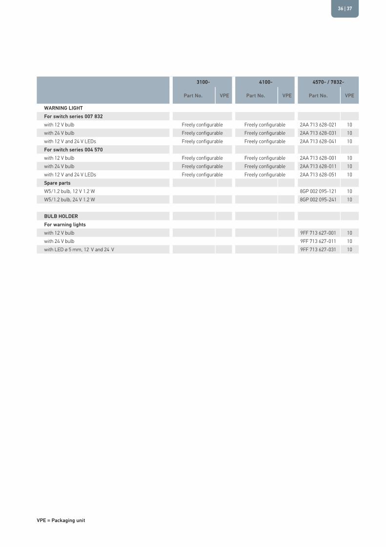
WARNING LIGHTFor switch series 007 832with 12 V bulb Freely configurable Freely configurable 2AA 713 628-021 10with 24 V bulb Freely configurable Freely configurable 2AA 713 628-031 10with 12 V and 24 V LEDs Freely configurable Freely configurable 2AA 713 628-041 10For switch series 004 570with 12 V bulb Freely configurable Freely configurable 2AA 713 628-001 10with 24 V bulb Freely configurable Freely configurable 2AA 713 628-011 10with 12 V and 24 V LEDs Freely configurable Freely configurable 2AA 713 628-051 10Spare partsW5/1.2 bulb, 12 V 1.2 W 8GP 002 095-121 10W5/1.2 bulb, 24 V 1.2 W 8GP 002 095-241 10
BULB HOLDERFor warning lightswith 12 V bulb 9FF 713 627-001 10with 24 V bulb 9FF 713 627-011 10with LED ø 5 mm, 12 V and 24 V 9FF 713 627-031 10
| 3736

ICON OVERVIEWN
o.
Sym
bol
Axle
Driv
e, W
heel
s,
Stee
ring
& Su
spen
sion
Brak
e Sy
stem
& C
ompr
esse
d-Ai
r Sy
stem
Engi
ne, T
rans
mis
sion
& C
lutc
h
Heat
ing,
Ven
tilat
ion
& Ai
r-Co
nditi
o-ni
ng S
yste
mCo
mfo
rt F
eatu
res
& In
terio
r Eq
uipm
ent
Glaz
ing,
Mirr
or &
W
inds
hiel
d Cl
eani
ng A
gent
Body
& L
ocki
ng S
yste
m
Secu
rity
Syst
ems
Inte
rior &
Ex
terio
r Lig
htin
g
Spec
ial A
pplic
atio
ns
0001 ✓0002 ✓0003 ✓0004 ✓0005 ✓0006 ✓0007 ✓0009 ✓0010 ✓0011 ✓0012 ✓0014 ✓0015 ✓ ✓0016 ✓ ✓0017 ✓ ✓0018 ✓0019 ✓0020 ✓0021 ✓0022 ✓0023 ✓0024 ✓0025 ✓0026 ✓
No.
Sym
bol
Axle
Driv
e, W
heel
s,
Stee
ring
& Su
spen
sion
Brak
e Sy
stem
& C
ompr
esse
d-Ai
r Sy
stem
Engi
ne, T
rans
mis
sion
& C
lutc
h
Heat
ing,
Ven
tilat
ion
& Ai
r-Co
nditi
o-ni
ng S
yste
mCo
mfo
rt F
eatu
res
& In
terio
r Eq
uipm
ent
Glaz
ing,
Mirr
or &
W
inds
hiel
d Cl
eani
ng A
gent
Body
& L
ocki
ng S
yste
m
Secu
rity
Syst
ems
Inte
rior &
Ex
terio
r Lig
htin
g
Spec
ial A
pplic
atio
ns
0027 ✓0028 ✓0029 ✓0030 ✓0031 ✓0032 ✓0033 ✓0034 ✓0035 ✓0036 ✓0037 ✓ ✓0038 ✓ ✓0039 ✓0040 ✓0041 ✓0042 ✓0043 ✓0044 ✓0045 ✓0046 ✓0047 ✓0048 ✓ ✓0049 ✓ ✓0050 ✓
No.
Sym
bol
Axle
Driv
e, W
heel
s,
Stee
ring
& Su
spen
sion
Brak
e Sy
stem
& C
ompr
esse
d-Ai
r Sy
stem
Engi
ne, T
rans
mis
sion
& C
lutc
h
Heat
ing,
Ven
tilat
ion
& Ai
r-Co
nditi
o-ni
ng S
yste
mCo
mfo
rt F
eatu
res
& In
terio
r Eq
uipm
ent
Glaz
ing,
Mirr
or &
W
inds
hiel
d Cl
eani
ng A
gent
Body
& L
ocki
ng S
yste
m
Secu
rity
Syst
ems
Inte
rior &
Ex
terio
r Lig
htin
g
Spec
ial A
pplic
atio
ns
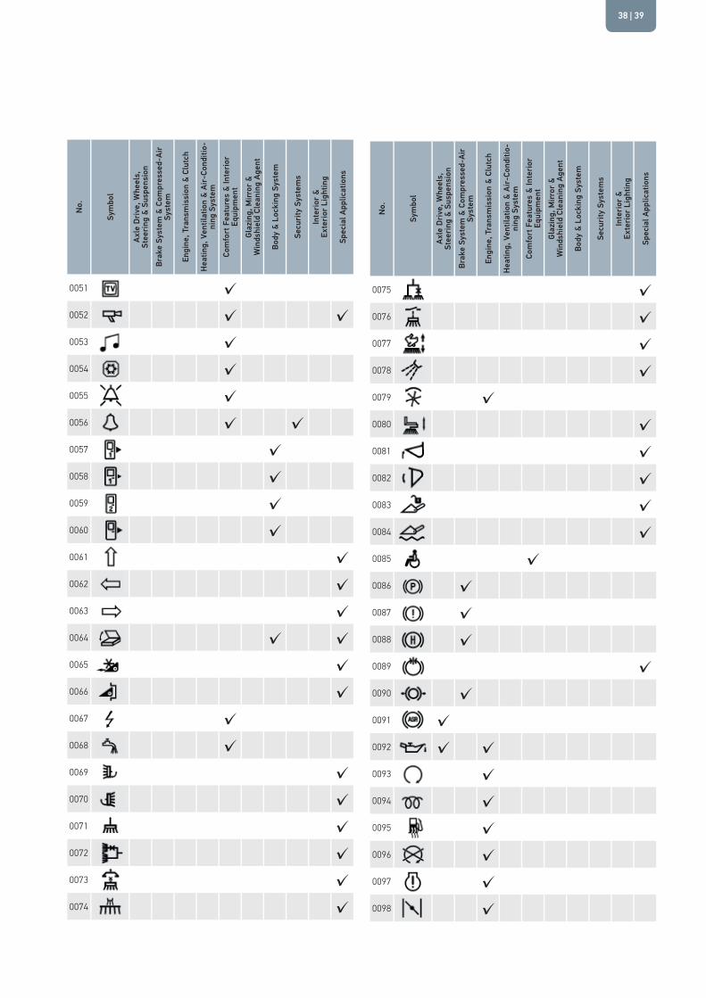
0051 ✓0052 ✓ ✓0053 ✓0054 ✓0055 ✓0056 ✓ ✓0057 ✓0058 ✓0059 ✓0060 ✓0061 ✓0062 ✓0063 ✓0064 ✓ ✓0065 ✓0066 ✓0067 ✓0068 ✓0069 ✓0070 ✓0071 ✓0072 ✓0073 ✓0074 ✓
No.
Sym
bol
Axle
Driv
e, W
heel
s,
Stee
ring
& Su
spen
sion
Brak
e Sy
stem
& C
ompr
esse
d-Ai
r Sy
stem
Engi
ne, T
rans
mis
sion
& C
lutc
h
Heat
ing,
Ven
tilat
ion
& Ai
r-Co
nditi
o-ni
ng S
yste
mCo
mfo
rt F
eatu
res
& In
terio
r Eq
uipm
ent
Glaz
ing,
Mirr
or &
W
inds
hiel
d Cl
eani
ng A
gent
Body
& L
ocki
ng S
yste
m
Secu
rity
Syst
ems
Inte
rior &
Ex
terio
r Lig
htin
g
Spec
ial A
pplic
atio
ns
0075 ✓0076 ✓0077 ✓0078 ✓0079 ✓0080 ✓0081 ✓0082 ✓0083 ✓0084 ✓0085 ✓0086 ✓0087 ✓0088 ✓0089 ✓0090 ✓0091 ✓0092 ✓ ✓0093 ✓0094 ✓0095 ✓0096 ✓0097 ✓0098 ✓
| 3938
ICON OVERVIEWN
o.
Sym
bol
Axle
Driv
e, W
heel
s,
Stee
ring
& Su
spen
sion
Brak
e Sy
stem
& C
ompr
esse
d-Ai
r Sy
stem
Engi
ne, T
rans
mis
sion
& C
lutc
h
Heat
ing,
Ven
tilat
ion
& Ai
r-Co
nditi
o-ni
ng S
yste
mCo
mfo
rt F
eatu
res
& In
terio
r Eq
uipm
ent
Glaz
ing,
Mirr
or &
W
inds
hiel
d Cl
eani
ng A
gent
Body
& L
ocki
ng S
yste
m
Secu
rity
Syst
ems
Inte
rior &
Ex
terio
r Lig
htin
g
Spec
ial A
pplic
atio
ns
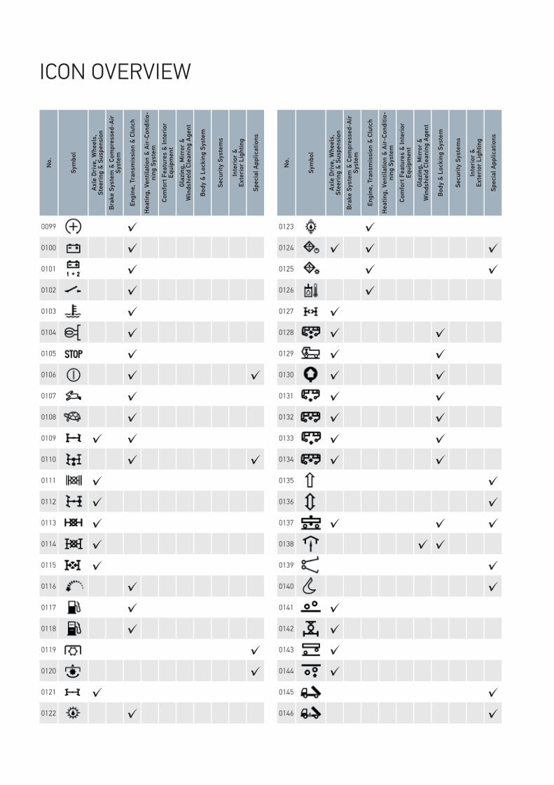
0099 ✓0100 ✓0101 ✓0102 ✓0103 ✓0104 ✓0105 ✓0106 ✓ ✓0107 ✓0108 ✓0109 ✓ ✓0110 ✓ ✓0111 ✓0112 ✓0113 ✓0114 ✓0115 ✓0116
✓0117 ✓0118 ✓0119 ✓0120 ✓0121 ✓0122 ✓
No.
Sym
bol
Axle
Driv
e, W
heel
s,
Stee
ring
& Su
spen
sion
Brak
e Sy
stem
& C
ompr
esse
d-Ai
r Sy
stem
Engi
ne, T
rans
mis
sion
& C
lutc
h
Heat
ing,
Ven
tilat
ion
& Ai
r-Co
nditi
o-ni
ng S
yste
mCo
mfo
rt F
eatu
res
& In
terio
r Eq
uipm
ent
Glaz
ing,
Mirr
or &
W
inds
hiel
d Cl
eani
ng A
gent
Body
& L
ocki
ng S
yste
m
Secu
rity
Syst
ems
Inte
rior &
Ex
terio
r Lig
htin
g
Spec
ial A
pplic
atio
ns
0123 ✓0124 ✓ ✓ ✓0125 ✓ ✓0126 ✓0127 ✓0128 ✓ ✓0129 ✓ ✓0130 ✓ ✓0131 ✓ ✓0132 ✓ ✓0133 ✓ ✓0134 ✓ ✓0135 ✓0136 ✓0137 ✓ ✓ ✓0138 ✓ ✓0139 ✓0140 ✓0141 ✓0142 ✓0143 ✓0144 ✓0145 ✓0146 ✓

No.
Sym
bol
Axle
Driv
e, W
heel
s,
Stee
ring
& Su
spen
sion
Brak
e Sy
stem
& C
ompr
esse
d-Ai
r Sy
stem
Engi
ne, T
rans
mis
sion
& C
lutc
h
Heat
ing,
Ven
tilat
ion
& Ai
r-Co
nditi
o-ni
ng S
yste
mCo
mfo
rt F
eatu
res
& In
terio
r Eq
uipm
ent
Glaz
ing,
Mirr
or &
W
inds
hiel
d Cl
eani
ng A
gent
Body
& L
ocki
ng S
yste
m
Secu
rity
Syst
ems
Inte
rior &
Ex
terio
r Lig
htin
g
Spec
ial A
pplic
atio
ns
0147 ✓0148 ✓0149 ✓ ✓0150 ✓ ✓0151 ✓ ✓0152 ✓ ✓0153 ✓ ✓0154 ✓0155 ✓0156 ✓0157 ✓0158 ✓0159 ✓0160 ✓0161 ✓0162 ✓0163 ✓ ✓0164 ✓0165 ✓0166 ✓0167 ✓0168 ✓ ✓0169 ✓ ✓0170 ✓ ✓
No.
Sym
bol
Axle
Driv
e, W
heel
s,
Stee
ring
& Su
spen
sion
Brak
e Sy
stem
& C
ompr
esse
d-Ai
r Sy
stem
Engi
ne, T
rans
mis
sion
& C
lutc
h
Heat
ing,
Ven
tilat
ion
& Ai
r-Co
nditi
o-ni
ng S
yste
mCo
mfo
rt F
eatu
res
& In
terio
r Eq
uipm
ent
Glaz
ing,
Mirr
or &
W
inds
hiel
d Cl
eani
ng A
gent
Body
& L
ocki
ng S
yste
m
Secu
rity
Syst
ems
Inte
rior &
Ex
terio
r Lig
htin
g
Spec
ial A
pplic
atio
ns
0194 ✓0195 ✓0205 ✓ ✓0206 ✓0207 ✓0208 ✓ ✓0209 ✓ ✓0210 ✓ ✓0211 ✓0212 ✓ ✓0213 ✓ ✓0214 ✓ ✓0215 ✓ ✓0216 ✓ ✓0217 ✓ ✓0218 ✓ ✓0219 ✓ ✓0220 ✓ ✓0221 ✓ ✓0222 ✓0223 ✓ ✓0224 ✓0225 ✓0226 ✓ ✓
| 4140

ICON OVERVIEWN
o.
Sym
bol
Axle
Driv
e, W
heel
s,
Stee
ring
& Su
spen
sion
Brak
e Sy
stem
& C
ompr
esse
d-Ai
r Sy
stem
Engi
ne, T
rans
mis
sion
& C
lutc
h
Heat
ing,
Ven
tilat
ion
& Ai
r-Co
nditi
o-ni
ng S
yste
mCo
mfo
rt F
eatu
res
& In
terio
r Eq
uipm
ent
Glaz
ing,
Mirr
or &
W
inds
hiel
d Cl
eani
ng A
gent
Body
& L
ocki
ng S
yste
m
Secu
rity
Syst
ems
Inte
rior &
Ex
terio
r Lig
htin
g
Spec
ial A
pplic
atio
ns
0227 ✓0228 ✓ ✓0229 ✓0230 ✓ ✓ ✓0231 ✓0232 ✓0234 ✓0235 ✓0236 ✓ ✓0237 ✓ ✓0238 ✓0239 ✓0240 ✓ ✓0241 ✓ ✓0242 ✓0243 ✓0244 ✓ ✓0245 ✓0246 ✓0247 ✓0248 ✓0249 ✓ ✓0250 ✓ ✓0251 ✓ ✓
No.
Sym
bol
Axle
Driv
e, W
heel
s,
Stee
ring
& Su
spen
sion
Brak
e Sy
stem
& C
ompr
esse
d-Ai
r Sy
stem
Engi
ne, T
rans
mis
sion
& C
lutc
h
Heat
ing,
Ven
tilat
ion
& Ai
r-Co
nditi
o-ni
ng S
yste
mCo
mfo
rt F
eatu
res
& In
terio
r Eq
uipm
ent
Glaz
ing,
Mirr
or &
W
inds
hiel
d Cl
eani
ng A
gent
Body
& L
ocki
ng S
yste
m
Secu
rity
Syst
ems
Inte
rior &
Ex
terio
r Lig
htin
g
Spec
ial A
pplic
atio
ns
0252 ✓ ✓0253 ✓0254 ✓0255 ✓ ✓0256 ✓ ✓0257 ✓ ✓0258 ✓ ✓0259 ✓ ✓0260 ✓0261 ✓0262 ✓0263 ✓ ✓0264 ✓0265 ✓0266 ✓0267 ✓0268 ✓ ✓0269 ✓0270 ✓0271 ✓0272 ✓ ✓0273 ✓0274 ✓ ✓0275 ✓

No.
Sym
bol
Axle
Driv
e, W
heel
s,
Stee
ring
& Su
spen
sion
Brak
e Sy
stem
& C
ompr
esse
d-Ai
r Sy
stem
Engi
ne, T
rans
mis
sion
& C
lutc
h
Heat
ing,
Ven
tilat
ion
& Ai
r-Co
nditi
o-ni
ng S
yste
mCo
mfo
rt F
eatu
res
& In
terio
r Eq
uipm
ent
Glaz
ing,
Mirr
or &
W
inds
hiel
d Cl
eani
ng A
gent
Body
& L
ocki
ng S
yste
m
Secu
rity
Syst
ems
Inte
rior &
Ex
terio
r Lig
htin
g
Spec
ial A
pplic
atio
ns
0276 ✓ ✓0277 ✓0278 ✓ ✓ ✓0279 ✓0280 ✓0281 ✓0282 ✓0283 ✓0284 ✓0285 ✓ ✓0286 ✓ ✓0287 ✓0288 ✓0289 ✓0290 ✓0291 ✓0292 ✓0293 ✓0294 ✓ ✓0295 ✓0296 ✓0297 ✓0298 ✓0299 ✓
No.
Sym
bol
Axle
Driv
e, W
heel
s,
Stee
ring
& Su
spen
sion
Brak
e Sy
stem
& C
ompr
esse
d-Ai
r Sy
stem
Engi
ne, T
rans
mis
sion
& C
lutc
h
Heat
ing,
Ven
tilat
ion
& Ai
r-Co
nditi
o-ni
ng S
yste
mCo
mfo
rt F
eatu
res
& In
terio
r Eq
uipm
ent
Glaz
ing,
Mirr
or &
W
inds
hiel
d Cl
eani
ng A
gent
Body
& L
ocki
ng S
yste
m
Secu
rity
Syst
ems
Inte
rior &
Ex
terio
r Lig
htin
g
Spec
ial A
pplic
atio
ns
0305 ✓0306 ✓0307 ✓ ✓0308 ✓ ✓0309 ✓0310 ✓0311 ✓0312 ✓ ✓0313 ✓0314 ✓ ✓0315 ✓0316 ✓0317 ✓ ✓0318 ✓ ✓0319 ✓0320 ✓0321 ✓0322 ✓0323 ✓0324 ✓ ✓0325 ✓ ✓0326 ✓ ✓ ✓0327 ✓0328 ✓
| 4342
ICON OVERVIEWN
o.
Sym
bol
Axle
Driv
e, W
heel
s,
Stee
ring
& Su
spen
sion
Brak
e Sy
stem
& C
ompr
esse
d-Ai
r Sy
stem
Engi
ne, T
rans
mis
sion
& C
lutc
h
Heat
ing,
Ven
tilat
ion
& Ai
r-Co
nditi
o-ni
ng S
yste
mCo
mfo
rt F
eatu
res
& In
terio
r Eq
uipm
ent
Glaz
ing,
Mirr
or &
W
inds
hiel
d Cl
eani
ng A
gent
Body
& L
ocki
ng S
yste
m
Secu
rity
Syst
ems
Inte
rior &
Ex
terio
r Lig
htin
g
Spec
ial A
pplic
atio
ns
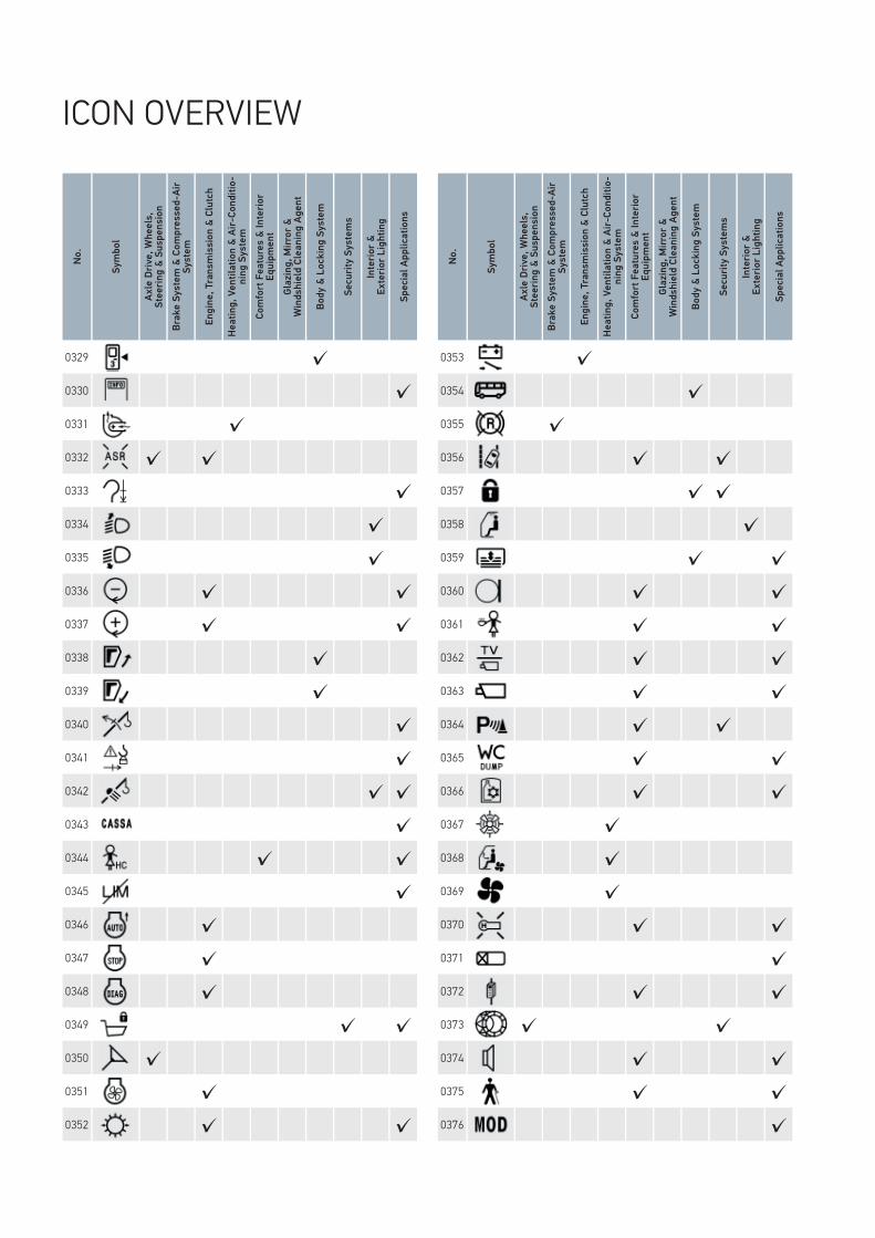
0329 ✓0330 ✓0331 ✓0332 ✓ ✓0333 ✓0334 ✓0335 ✓0336 ✓ ✓0337 ✓ ✓0338 ✓0339 ✓0340 ✓0341 ✓0342 ✓ ✓0343 ✓0344 ✓ ✓0345 ✓0346 ✓0347 ✓0348 ✓0349 ✓ ✓0350 ✓0351 ✓0352 ✓ ✓
No.
Sym
bol
Axle
Driv
e, W
heel
s,
Stee
ring
& Su
spen
sion
Brak
e Sy
stem
& C
ompr
esse
d-Ai
r Sy
stem
Engi
ne, T
rans
mis
sion
& C
lutc
h
Heat
ing,
Ven
tilat
ion
& Ai
r-Co
nditi
o-ni
ng S
yste
mCo
mfo
rt F
eatu
res
& In
terio
r Eq
uipm
ent
Glaz
ing,
Mirr
or &
W
inds
hiel
d Cl
eani
ng A
gent
Body
& L
ocki
ng S
yste
m
Secu
rity
Syst
ems
Inte
rior &
Ex
terio
r Lig
htin
g
Spec
ial A
pplic
atio
ns
0353 ✓0354 ✓0355 ✓0356 ✓ ✓0357 ✓ ✓0358 ✓0359 ✓ ✓0360 ✓ ✓0361 ✓ ✓0362 ✓ ✓0363 ✓ ✓0364 ✓ ✓0365 ✓ ✓0366 ✓ ✓0367 ✓0368 ✓0369 ✓0370 ✓ ✓0371 ✓0372 ✓ ✓0373 ✓ ✓0374 ✓ ✓0375 ✓ ✓0376 ✓
No.
Sym
bol
Axle
Driv
e, W
heel
s,
Stee
ring
& Su
spen
sion
Brak
e Sy
stem
& C
ompr
esse
d-Ai
r Sy
stem
Engi
ne, T
rans
mis
sion
& C
lutc
h
Heat
ing,
Ven
tilat
ion
& Ai
r-Co
nditi
o-ni
ng S
yste
mCo
mfo
rt F
eatu
res
& In
terio
r Eq
uipm
ent
Glaz
ing,
Mirr
or &
W
inds
hiel
d Cl
eani
ng A
gent
Body
& L
ocki
ng S
yste
m
Secu
rity
Syst
ems
Inte
rior &
Ex
terio
r Lig
htin
g
Spec
ial A
pplic
atio
ns
0377 ✓0378 ✓0379 ✓0380 ✓ ✓0381 ✓ ✓0382 ✓0383 ✓0384 ✓ ✓0385 ✓ ✓0386 ✓0387 ✓0388 ✓0389 ✓ ✓0390 ✓ ✓0391 ✓ ✓0392 ✓0393 ✓0394 ✓0395 ✓0396 ✓0397 ✓ ✓0398 ✓ ✓ ✓0399 ✓ ✓0400 ✓
No.
Sym
bol
Axle
Driv
e, W
heel
s,
Stee
ring
& Su
spen
sion
Brak
e Sy
stem
& C
ompr
esse
d-Ai
r Sy
stem
Engi
ne, T
rans
mis
sion
& C
lutc
h
Heat
ing,
Ven
tilat
ion
& Ai
r-Co
nditi
o-ni
ng S
yste
mCo
mfo
rt F
eatu
res
& In
terio
r Eq
uipm
ent
Glaz
ing,
Mirr
or &
W
inds
hiel
d Cl
eani
ng A
gent
Body
& L
ocki
ng S
yste
m
Secu
rity
Syst
ems
Inte
rior &
Ex
terio
r Lig
htin
g
Spec
ial A
pplic
atio
ns
0401 ✓0402 ✓ ✓0403 ✓0404 ✓0405 ✓ ✓0406 ✓0407 ✓0408 ✓0409 ✓ ✓0410 ✓ ✓0411 ✓ ✓0412 ✓ ✓0413 ✓0414 ✓ ✓0415 ✓ ✓0416 ✓ ✓0417 ✓ ✓0418 ✓ ✓0419 ✓ ✓0420 ✓0421 ✓0422 ✓0423 ✓0424 ✓
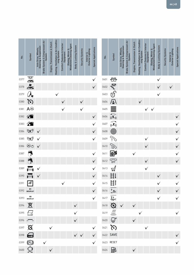
| 4544

ICON OVERVIEWN
o.
Sym
bol
Axle
Driv
e, W
heel
s,
Stee
ring
& Su
spen
sion
Brak
e Sy
stem
& C
ompr
esse
d-Ai
r Sy
stem
Engi
ne, T
rans
mis
sion
& C
lutc
h
Heat
ing,
Ven
tilat
ion
& Ai
r-Co
nditi
o-ni
ng S
yste
mCo
mfo
rt F
eatu
res
& In
terio
r Eq
uipm
ent
Glaz
ing,
Mirr
or &
W
inds
hiel
d Cl
eani
ng A
gent
Body
& L
ocki
ng S
yste
m
Secu
rity
Syst
ems
Inte
rior &
Ex
terio
r Lig
htin
g
Spec
ial A
pplic
atio
ns
0425 ✓0426 ✓0427 ✓0428 ✓0429 ✓0433 ✓0434 ✓ ✓0435 ✓ ✓0436 ✓ ✓0437 ✓0438 ✓0439 ✓0440 ✓0441 ✓ ✓0442 ✓ ✓0443 ✓0444 ✓ ✓0445 ✓0446 ✓0447 ✓ ✓0448 ✓ ✓0449 ✓0450 ✓0451 ✓
No.
Sym
bol
Axle
Driv
e, W
heel
s,
Stee
ring
& Su
spen
sion
Brak
e Sy
stem
& C
ompr
esse
d-Ai
r Sy
stem
Engi
ne, T
rans
mis
sion
& C
lutc
h
Heat
ing,
Ven
tilat
ion
& Ai
r-Co
nditi
o-ni
ng S
yste
mCo
mfo
rt F
eatu
res
& In
terio
r Eq
uipm
ent
Glaz
ing,
Mirr
or &
W
inds
hiel
d Cl
eani
ng A
gent
Body
& L
ocki
ng S
yste
m
Secu
rity
Syst
ems
Inte
rior &
Ex
terio
r Lig
htin
g
Spec
ial A
pplic
atio
ns
0452 ✓0453 ✓0454 ✓0455 ✓0456 ✓ ✓0457 ✓0458 ✓0459 ✓0460 ✓ ✓0461 ✓ ✓0462 ✓ ✓0463 ✓0465 ✓0466 ✓ ✓0467 ✓ ✓0468 ✓0469 ✓0470 ✓0471 ✓0472 ✓0473 ✓0474 ✓0475 ✓0476 ✓
No.
Sym
bol
Axle
Driv
e, W
heel
s,
Stee
ring
& Su
spen
sion
Brak
e Sy
stem
& C
ompr
esse
d-Ai
r Sy
stem
Engi
ne, T
rans
mis
sion
& C
lutc
h
Heat
ing,
Ven
tilat
ion
& Ai
r-Co
nditi
o-ni
ng S
yste
mCo
mfo
rt F
eatu
res
& In
terio
r Eq
uipm
ent
Glaz
ing,
Mirr
or &
W
inds
hiel
d Cl
eani
ng A
gent
Body
& L
ocki
ng S
yste
m
Secu
rity
Syst
ems
Inte
rior &
Ex
terio
r Lig
htin
g
Spec
ial A
pplic
atio
ns
0477 ✓0478 ✓0479 ✓0480 ✓0481 ✓0482 ✓0483 ✓0484 ✓0485 ✓0486 ✓0487 ✓ ✓0488 ✓0489 ✓ ✓0490 ✓0491 ✓0492 ✓0493 ✓0494 ✓ ✓0495 ✓0496 ✓0497 ✓ ✓0498 ✓ ✓0499 ✓0500 ✓
No.
Sym
bol
Axle
Driv
e, W
heel
s,
Stee
ring
& Su
spen
sion
Brak
e Sy
stem
& C
ompr
esse
d-Ai
r Sy
stem
Engi
ne, T
rans
mis
sion
& C
lutc
h
Heat
ing,
Ven
tilat
ion
& Ai
r-Co
nditi
o-ni
ng S
yste
mCo
mfo
rt F
eatu
res
& In
terio
r Eq
uipm
ent
Glaz
ing,
Mirr
or &
W
inds
hiel
d Cl
eani
ng A
gent
Body
& L
ocki
ng S
yste
m
Secu
rity
Syst
ems
Inte
rior &
Ex
terio
r Lig
htin
g
Spec
ial A
pplic
atio
ns
0501 ✓0502 ✓0503 ✓0504 ✓0505 ✓ ✓0506 ✓ ✓0507 ✓0508 ✓0509 ✓0510 ✓0511 ✓ ✓0512 ✓0513 ✓0514 ✓ ✓0515 ✓ ✓0516 ✓ ✓0517 ✓ ✓0518 ✓ ✓0519 ✓ ✓0520 ✓0521 ✓0522 ✓0523 ✓0524 ✓ ✓
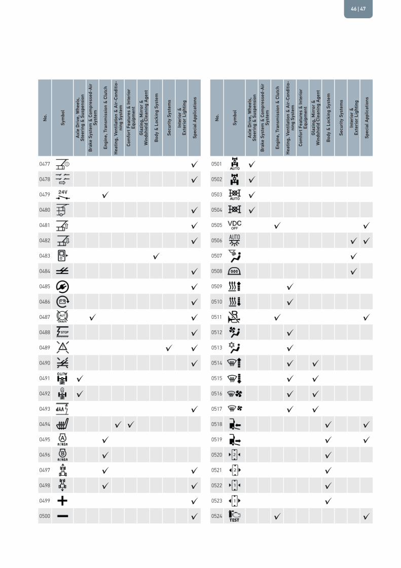
| 4746

ICON OVERVIEWN
o.
Sym
bol
Axle
Driv
e, W
heel
s,
Stee
ring
& Su
spen
sion
Brak
e Sy
stem
& C
ompr
esse
d-Ai
r Sy
stem
Engi
ne, T
rans
mis
sion
& C
lutc
h
Heat
ing,
Ven
tilat
ion
& Ai
r-Co
nditi
o-ni
ng S
yste
mCo
mfo
rt F
eatu
res
& In
terio
r Eq
uipm
ent
Glaz
ing,
Mirr
or &
W
inds
hiel
d Cl
eani
ng A
gent
Body
& L
ocki
ng S
yste
m
Secu
rity
Syst
ems
Inte
rior &
Ex
terio
r Lig
htin
g
Spec
ial A
pplic
atio
ns
0525 ✓ ✓0526 ✓ ✓0527 ✓ ✓ ✓0528 ✓0529 ✓0530 ✓0531 ✓0532 ✓0533 ✓0534 ✓0535 ✓0536 ✓0537 ✓0538 ✓ ✓0539 ✓ ✓0540 ✓0541 ✓0542 ✓ ✓0543 ✓0544 ✓0545 ✓ ✓0546 ✓0547 ✓0548 ✓
No.
Sym
bol
Axle
Driv
e, W
heel
s,
Stee
ring
& Su
spen
sion
Brak
e Sy
stem
& C
ompr
esse
d-Ai
r Sy
stem
Engi
ne, T
rans
mis
sion
& C
lutc
h
Heat
ing,
Ven
tilat
ion
& Ai
r-Co
nditi
o-ni
ng S
yste
mCo
mfo
rt F
eatu
res
& In
terio
r Eq
uipm
ent
Glaz
ing,
Mirr
or &
W
inds
hiel
d Cl
eani
ng A
gent
Body
& L
ocki
ng S
yste
m
Secu
rity
Syst
ems
Inte
rior &
Ex
terio
r Lig
htin
g
Spec
ial A
pplic
atio
ns
0549 ✓0550 ✓0551 ✓0552 ✓ ✓0553 ✓0554 ✓0555 ✓0556 ✓0557 ✓0558 ✓0559 ✓0560 ✓0561 ✓ ✓0562 ✓0563 ✓0564 ✓0565 ✓0566 ✓0567 ✓0568 ✓0569 ✓0570 ✓0571 ✓0572 ✓ ✓

No.
Sym
bol
Axle
Driv
e, W
heel
s,
Stee
ring
& Su
spen
sion
Brak
e Sy
stem
& C
ompr
esse
d-Ai
r Sy
stem
Engi
ne, T
rans
mis
sion
& C
lutc
h
Heat
ing,
Ven
tilat
ion
& Ai
r-Co
nditi
o-ni
ng S
yste
mCo
mfo
rt F
eatu
res
& In
terio
r Eq
uipm
ent
Glaz
ing,
Mirr
or &
W
inds
hiel
d Cl
eani
ng A
gent
Body
& L
ocki
ng S
yste
m
Secu
rity
Syst
ems
Inte
rior &
Ex
terio
r Lig
htin
g
Spec
ial A
pplic
atio
ns
0573 ✓ ✓0574 ✓0575 ✓0576 ✓0577 ✓ ✓0578 ✓ ✓0579 ✓0580 ✓0581 ✓0582 ✓0583 ✓0584 ✓0585 ✓0586 ✓0587 ✓0588 ✓ ✓0589 ✓ ✓0590 ✓0591 ✓0592 ✓0593 ✓0594 ✓0595 ✓0596 ✓
No.
Sym
bol
Axle
Driv
e, W
heel
s,
Stee
ring
& Su
spen
sion
Brak
e Sy
stem
& C
ompr
esse
d-Ai
r Sy
stem
Engi
ne, T
rans
mis
sion
& C
lutc
h
Heat
ing,
Ven
tilat
ion
& Ai
r-Co
nditi
o-ni
ng S
yste
mCo
mfo
rt F
eatu
res
& In
terio
r Eq
uipm
ent
Glaz
ing,
Mirr
or &
W
inds
hiel
d Cl
eani
ng A
gent
Body
& L
ocki
ng S
yste
m
Secu
rity
Syst
ems
Inte
rior &
Ex
terio
r Lig
htin
g
Spec
ial A
pplic
atio
ns
0597 ✓598 ✓ ✓599 ✓ ✓600 ✓601 ✓602 ✓603 ✓ ✓
0604 ✓0605 ✓0606 ✓0607 ✓0608 ✓0609 ✓0610 ✓ ✓0611 ✓0612 ✓0613 ✓0614 ✓0615 ✓0616 ✓ ✓0617 ✓ ✓0618 ✓0619 ✓0620 ✓
| 4948

ICON OVERVIEWN
o.
Sym
bol
Axle
Driv
e, W
heel
s,
Stee
ring
& Su
spen
sion
Brak
e Sy
stem
& C
ompr
esse
d-Ai
r Sy
stem
Engi
ne, T
rans
mis
sion
& C
lutc
h
Heat
ing,
Ven
tilat
ion
& Ai
r-Co
nditi
o-ni
ng S
yste
mCo
mfo
rt F
eatu
res
& In
terio
r Eq
uipm
ent
Glaz
ing,
Mirr
or &
W
inds
hiel
d Cl
eani
ng A
gent
Body
& L
ocki
ng S
yste
m
Secu
rity
Syst
ems
Inte
rior &
Ex
terio
r Lig
htin
g
Spec
ial A
pplic
atio
ns
0621 ✓622 ✓623 ✓624 ✓625 ✓626 ✓627 ✓628 ✓629 ✓630 ✓631 ✓632 ✓633 ✓ ✓634 ✓ ✓635 ✓636 ✓637 ✓638 ✓639 ✓640 ✓641 ✓ ✓642 ✓ ✓643 ✓ ✓644 ✓ ✓
No.
Sym
bol
Axle
Driv
e, W
heel
s,
Stee
ring
& Su
spen
sion
Brak
e Sy
stem
& C
ompr
esse
d-Ai
r Sy
stem
Engi
ne, T
rans
mis
sion
& C
lutc
h
Heat
ing,
Ven
tilat
ion
& Ai
r-Co
nditi
o-ni
ng S
yste
mCo
mfo
rt F
eatu
res
& In
terio
r Eq
uipm
ent
Glaz
ing,
Mirr
or &
W
inds
hiel
d Cl
eani
ng A
gent
Body
& L
ocki
ng S
yste
m
Secu
rity
Syst
ems
Inte
rior &
Ex
terio
r Lig
htin
g
Spec
ial A
pplic
atio
ns
645 ✓ ✓646 ✓ ✓647 ✓648 ✓649 ✓650 ✓651 ✓652 ✓653 ✓654 ✓
0655 ✓0656 ✓ ✓0657 ✓ ✓0658 ✓0659 ✓ ✓0660 ✓0661 ✓0662 ✓0663 ✓ ✓0664 ✓ ✓0665 ✓ ✓0666 ✓ ✓0667 ✓0668 ✓

No.
Sym
bol
Axle
Driv
e, W
heel
s,
Stee
ring
& Su
spen
sion
Brak
e Sy
stem
& C
ompr
esse
d-Ai
r Sy
stem
Engi
ne, T
rans
mis
sion
& C
lutc
h
Heat
ing,
Ven
tilat
ion
& Ai
r-Co
nditi
o-ni
ng S
yste
mCo
mfo
rt F
eatu
res
& In
terio
r Eq
uipm
ent
Glaz
ing,
Mirr
or &
W
inds
hiel
d Cl
eani
ng A
gent
Body
& L
ocki
ng S
yste
m
Secu
rity
Syst
ems
Inte
rior &
Ex
terio
r Lig
htin
g
Spec
ial A
pplic
atio
ns
0669 ✓0670 ✓0671 ✓0672 ✓0673 ✓ ✓0674 ✓675 ✓676 ✓677 ✓ ✓678 ✓679 ✓680 ✓681 ✓682 ✓ ✓683 ✓ ✓684 ✓685 ✓686 ✓687 ✓688 ✓689 ✓690 ✓691 ✓692 ✓
No.
Sym
bol
Axle
Driv
e, W
heel
s,
Stee
ring
& Su
spen
sion
Brak
e Sy
stem
& C
ompr
esse
d-Ai
r Sy
stem
Engi
ne, T
rans
mis
sion
& C
lutc
h
Heat
ing,
Ven
tilat
ion
& Ai
r-Co
nditi
o-ni
ng S
yste
mCo
mfo
rt F
eatu
res
& In
terio
r Eq
uipm
ent
Glaz
ing,
Mirr
or &
W
inds
hiel
d Cl
eani
ng A
gent
Body
& L
ocki
ng S
yste
m
Secu
rity
Syst
ems
Inte
rior &
Ex
terio
r Lig
htin
g
Spec
ial A
pplic
atio
ns
693 ✓694 ✓695 ✓696 ✓ ✓697 ✓698 ✓699 ✓700 ✓ ✓701 ✓702 ✓ ✓703 ✓704 ✓705 ✓ ✓706 ✓707 ✓708 ✓709 ✓710 ✓711 ✓712 ✓713 ✓714 ✓715 ✓ ✓716 ✓
| 5150
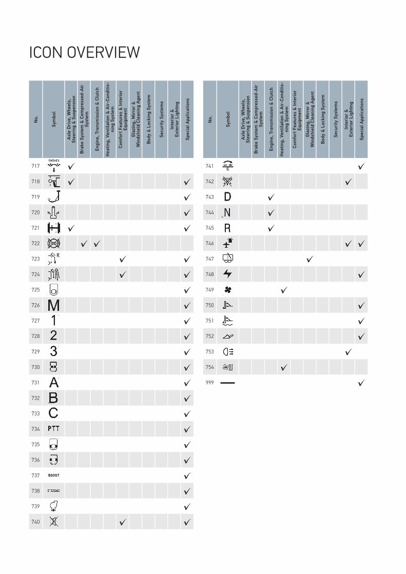
ICON OVERVIEW
No.
Sym
bol
Axle
Driv
e, W
heel
s,
Stee
ring
& Su
spen
sion
Brak
e Sy
stem
& C
ompr
esse
d-Ai
r Sy
stem
Engi
ne, T
rans
mis
sion
& C
lutc
h
Heat
ing,
Ven
tilat
ion
& Ai
r-Co
nditi
o-ni
ng S
yste
mCo
mfo
rt F
eatu
res
& In
terio
r Eq
uipm
ent
Glaz
ing,
Mirr
or &
W
inds
hiel
d Cl
eani
ng A
gent
Body
& L
ocki
ng S
yste
m
Secu
rity
Syst
ems
Inte
rior &
Ex
terio
r Lig
htin
g
Spec
ial A
pplic
atio
ns
741 ✓742 ✓743 ✓744 ✓745 ✓746 ✓ ✓747 ✓748 ✓749 ✓750 ✓751 ✓752 ✓753 ✓754 ✓999 ✓
No.
Sym
bol
Axle
Driv
e, W
heel
s,
Stee
ring
& Su
spen
sion
Brak
e Sy
stem
& C
ompr
esse
d-Ai
r Sy
stem
Engi
ne, T
rans
mis
sion
& C
lutc
h
Heat
ing,
Ven
tilat
ion
& Ai
r-Co
nditi
o-ni
ng S
yste
mCo
mfo
rt F
eatu
res
& In
terio
r Eq
uipm
ent
Glaz
ing,
Mirr
or &
W
inds
hiel
d Cl
eani
ng A
gent
Body
& L
ocki
ng S
yste
m
Secu
rity
Syst
ems
Inte
rior &
Ex
terio
r Lig
htin
g
Spec
ial A
pplic
atio
ns
717 ✓718 ✓ ✓719 ✓720 ✓721 ✓ ✓722 ✓ ✓723 ✓ ✓724 ✓ ✓725 ✓726 ✓727 ✓728 ✓729 ✓730 ✓731 ✓732 ✓733 ✓734 ✓735 ✓736 ✓737 ✓738 ✓739 ✓740 ✓ ✓

HELLA KGaA Hueck & Co.Rixbecker Straße 7559552 Lippstadt, GermanyTel.: +49 2941 38-0Fax: +49 2941 38-7133Internet: www.hella.com
© HELLA KGaA Hueck & Co., LippstadtJ01265/05.17 Subject to technical and price modifications.
For more information seewww.hella.com/switch