125LB ATV RECEIVER MOUNT SPREADER - Northern Tool · 2. Read and follow directions on the package...
15
125LB ATV RECEIVER MOUNT SPREADER Model AS-125ATV12 12112012
Transcript of 125LB ATV RECEIVER MOUNT SPREADER - Northern Tool · 2. Read and follow directions on the package...

125LB ATV RECEIVER MOUNT SPREADER
Model AS-125ATV1212112012

1. Be sure to wear safety glasses, a dust mask, and proper clothing to prevent coming in contact with any chemicals or dangerous materials that are being applied by this spreader.
2. Make sure to remove any contents that are in the spreader’s hopper before attaching, detaching, or lifting this unit.
3. Avoid attaching and detaching this unit alone. To avoid damage to this unit and injury always have someone help attach and detach due to shape and weight of this unit.
4. Always refer to the load rating for the vehicle which is located in the vehicle’s owners manual. Make sure that the unit weight of 37lbs plus the weight of the contents in the hopper do not exceed that of the vehicle’s recommended load rating.
5. To avoid damage to this unit and injury NEVER overload the hopper.
6. Stay clear of all moving and spinning parts or objects of this unit
7. Always follow directions on the package of whatever you are applying with this unit.
SAFETY PRECAUTIONS
Operation InstructionsOperation Instructions1. After assembly attach to front or rear receiver of vehicle.
2. Read and follow directions on the package of the material being spread by this unit.
3. Fill hopper with desired material to be spread by this unit not exceeding maximum load of 125lbs.
4. Adjust the handle on the gauge assembly so that it is at the desired setting. Then tighten the wing nut on the gauge assembly to set the desired opening. This allows the driver to set the opening to the same place every time while driving the vehicle. See page 3 for spread calculations.
5. Adjust handle on the gauge assembly until desired amount of spreading material is flowing out of the hopper onto the turning plate.
6. Flip rocker switch on cable assembly to on position and begin spreading.
7. Turn Rocker switch off when wanting to stop or pause spreading.
8. Empty and clean hopper when finished.
1

Note: Settings for this product need to be determined byuser since factors such as coarseness and density of “material used” affect the spread rates. See page 3 “rate worksheet” to calculate approximate spread rates.
When Rate settings are not available, follow these guidelines to calculate spread rates:
On the bag of material to spread, you will find recommended spread rates, usually in terms to the effect of: so many pounds will cover so many sq. ft.
Read these steps, then refer to the guide (worksheet page 3)
1.Determine how much material to apply per 1,000 sq. ft.2. Measure off a distance of 50ft, preferably on a paved area (ie: parking lot)3. Weigh out enough material from bag to fill hopper ½ full (recommend at least ½ full hopper)
Record weight for later.Record weight for later.4. Set the stop at position with opening of hopper at position you feel appropriate. 5. Now with hopper ½ full, bring vehicle to desired speed before start line of your 50 ft test area.
When you arrive at start line, turn on spreader, then off at finish line6. Stop the vehicle and note the width of spread path from your test run.7. Repeat if necessary; Then empty remaining material from hopper back to your weighing
device and record new weight.8. Be sure to record your results, see below guide on page 3.
2

On the bag of material to spread, you will find recommended spread rates, usually in terms to the effect of: so many pounds will cover so many sq. ft.
Find your Desired Application (spread) RateExample: To find your desired rate, divide the area (sq. ft.) that bag of material covers by the weight of the bag of material itself. Then multiply by 1,000.
Example: 25lb bag / 2000 sq ft coverage = .0125 .0125 x 1,000 = 12.5 (12.5 is your desired lbs per 1,000 sq. feet)
Record Desired Rate = (lbs per 1,000 sq. ft.) _________
TEST RUN to DETERIME SPREAD RATE:
• Determine lbs (weight) of Material in Hopper for Test Area_________ Weight of Material put into Hopper (Example: pour a 25lb bag into spreader)(-)_______ Subtract Weight of Material in Hopper (After Test Area is spread)(=)_______ Weight of Material Used (will be used below)
• Test Area Measurements_________ Length of Test Area (Recommend: 50 ft)(x)_______ Width of Spread Area(=)_______ Total Spread Area
3
(=)_______ Total Spread AreaDetermine Rate of SpreadDivide the Weight of Material Used in #2, by your Total Spread Area in #3.Weight of Material Used/Total Spread Area = lbs per sq. ft.Example: 2 lbs / 500 ft = .004Multiply lbs per sq ft (x)1000 = _____ lbs per 1000 sq ftExample: .004 x 1000 = 4Compare these results to your desired application rate in #1.Adjust the rate setting stop on the spreader accordingly and run test area again.Example: Adjust 2 times more open to achieve double the rate of test. Now you should approx. match your desired application in #1.Repeat the process if necessary until you achieve your desired application rate.
Settings and guidelines furnished on this Rate Worksheet are intended as a guide only. Variations in materials applied, ground roughness, speed of operator, may affect rate.There is no warranty as to the rate of coverage derived from above guidelines.

Carton Contents
NOTE: If you have questions, problems, or missing parts please call our customer service before returning to your retailer. Contact us at 218-943-6296 ,8 a.m.-5 p.m., Monday-Friday CST.
4

Assembly Instructions
Step 1: 1. Connect the deflector plate (#16) to the crossbeam tube (#17) using hex bolt M6x16 (#5), hex lock nut M6 (#15) and big flat washer Ø6 (#4). And then tighten them.2. Connect the crossbeam tube (#17) , connecting rod (#18) and hopper assemble tube (#14) using hex bolt M6x40 (#3), hex lock nut M6 (#15) and flat washer Ø6 (#50). Don't tighten them.
5

Step 2: Assemble the connecting tube assembly (#25) and extension tube (#28) using “U” bolt (#29), lock washer Ø12 (#26) and hex lock nut M12 (#27), then tighten it. NOTE: extension tube (#28) can be reversed to fit 1.25” or 2” receiver (see step 7 for more detail.)
6

Step 3: Connect the hopper assemble tube (#14) and spacer plate(#21) using hexbolt M6x40 (#3), hex bolt M6x20 (#20) ,hex lock nut M6 (#15) and flat washer
Ø6 (#50). Fully tighten.
7

Step 4: Assemble the connecting tube assembly (#25) and hopper tube assembly (#14) using hex bolt M10x25 (#22), lock washer Ø10 (#23) and flat washer Ø10 (#24). Fully tighten.
8

Step 5: 1. Pull out the switch box on the cable assembly , insert switch into the hole on the
gauge base plate , then plug-in the cable, and connect the other end of the cable with the cable on the motor.
2. Secure the gauge base plate(#34) and cable assembly (#57) using screw M5x12 (#11), Spring washer Ø5 (#63) mounting the clamp press plate (#64).
9
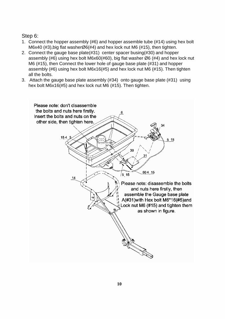
Step 6: 1. Connect the hopper assembly (#6) and hopper assemble tube (#14) using hex bolt
M6x40 (#3),big flat washerØ6(#4) and hex lock nut M6 (#15), then tighten.2. Connect the gauge base plate(#31) center spacer busing(#30) and hopper
assembly (#6) using hex bolt M6x60(#60), big flat washer Ø6 (#4) and hex lock nut M6 (#15), then Connect the lower hole of gauge base plate (#31) and hopper assembly (#6) using hex bolt M6x16(#5) and hex lock nut M6 (#15). Then tighten all the bolts.
3. Attach the gauge base plate assembly (#34) onto gauge base plate (#31) using hex bolt M6x16(#5) and hex lock nut M6 (#15). Then tighten.
10

Step 7:Tighten all the nuts and bolts.
11

Exploded Diagram
12

REF# DESCRIPTION QTY
1 RivetΦ5x13 6
2 Big Flat WasherΦ5 6
3 Hex Bolt M6x40 14
4 Big Flat WasherΦ6 12
5 Hex Bolt M6x16 10
6 Hopper Assembly 1
7 Wire Clamp 1
8 Shaft Bushing 1
9 Fixed Adjustable Plate 1
10 Link Clamp Press Plate 2
11 Screw M5x12 6
12 Nylon Lock Nut M5 4
13 Active Adjustable Plate 1
14 Hopper Assemble Tube 1
15 Nylon Lock Nut M6 28
16 Deflector A 1
17 Crossbeam Tube Assembly 1
Part ListREF# DESCRIPTION QTY
33 Fixed Plate 1
34 Gauge Base Plate 1
35 Step Bolt M6X25 1
36 External Teeth Lock Washer Φ8 1
37 Nylon Washer 1
38 Gauge & Level Assembly 1
39 Adjustable Handle 1
40 Wing Nut 1
41 Hex Bolt M6x35 1
42 Screw M4X20 1
43 Impeller 1
44 Shaft Φ10x135 1
45 Cotter Pin Φ4x30 1
46 Shaft Connecting Tube 1
47 Nylon Lock Nut M4 1
48 Screw M6x16 2
49 Lock Washer Φ6 217 Crossbeam Tube Assembly 1
18 Connecting Rod 2
19 Tube End CapΦ25X13 2
20 Hex Bolt M6X20 2
21 Spacer Plate C 1
22 Hex Bolt M10x25 2
23 Lock Washer Φ10 2
24 Flat Washer Φ10 2
25 Connecting Tube Assembly 1
26 Lock Washer Φ12 4
27 Hex Lock Nut M12 4
28 Extension Tube A 1
29 "U"Bolt 2
30 Center Bushing 1
31 Gauge Base Plate A 1
32 R Pin 1
13
49 Lock Washer Φ6 2
50 Flat Washer Φ6 8
51 Ribbon 1
52 Motor Assemble Plate 1
53 Motor Cover 1
54 Motor 1
55 Motor Cap 1
56 Adjustable Rod Assembly 1
57 Cable Assembly 1
58 Rain Cover 1
59 Spacer Bushing 1
60 Hex Bolt M6x60 1
61 Screw M4x25 1
62 Handle Grip 1
63 Spring Washer Φ5 2
64 Link Clamp Press Plate A 1

For replacement parts and technical questions, please call 1-218-943-6296.
WARRANTYOne-year limited warranty
TGPO Box 203
Miltona, MN 56354Made in CHINA
14