1.2.5 Straightness 1.3.1 Choice of arrangement type 1.3.2 ... · 1.3.1 CHOICE OF ARRANGEMENT TYPE...
33
TABLE OF CONTENTS 1.1 UNITS AND DEFINITIONS 12 1.2 PRECISION AND TOLERANCES 13 1.2.1 Qualities 13 1.2.2 Profile tolerances 13 1.2.3 Lengths, hole distances 13 1.2.4 Matching 14 1.2.5 Straightness 15 1.2.6 Rolling elements 15 1.3 APPLICATION FEATURES 16 1.3.1 Choice of arrangement type 16 1.3.2 Determination of guideway and cage lengths 17 1.3.3 Hole types and hole patterns 18 1.3.4 End pieces and wipers 20 1.3.5 Load rating, load carrying capacity 21 1.3.5.1 Basic static load rating 21 1.3.5.2 Static load carrying capacity 21 1.3.5.3 Basic dynamic load rating 22 1.3.5.4 Dynamic load carrying capacity and rating life 22 1.3.5.5 Effective load rating 24 1.3.5.6 Correction factors for load carrying capacity 25 1.3.5.7 Eccentric load 26 1.3.5.8 Calculation 27 1.4 RIGIDITY 32 1.5 PRELOAD 34 1.5.1 Setting the preload 34 1.5.1.1 Pressure screws 35 1.5.1.2 Guideways with adjusting gib 35 1.6 LUBRICATION 36 1.6.1 Lubricants 36 1.6.2 Lubricating with grease 36 1.6.2.1 Primary operation and grease quantity 36 1.6.2.2 Relubrication 37 1.6.3 Lubricating with oil 37 1.7 FRICTION 38 1.8 PROTECTION AGAINST SOILING 39 1.9 OPERATING LIMITS 39 1.10 INSTALLATION GUIDELINES 40 1.10.1 Precision of the connecting structure 40 1.10.2 Assembly instructions 41 1.10.2.1 Prior to installation 41 1.10.2.2 Closed layout 42 1.10.2.3 Open layout 43 PRODUCT TECHNOLOGY 11
Transcript of 1.2.5 Straightness 1.3.1 Choice of arrangement type 1.3.2 ... · 1.3.1 CHOICE OF ARRANGEMENT TYPE...

TABLE OF CONTENTS
1.1 UNITS AND DEFINITIONS 12
1.2 PRECISION AND TOLERANCES 13
1.2.1 Qualities 131.2.2 Profiletolerances 13 1.2.3 Lengths,holedistances 131.2.4 Matching 141.2.5 Straightness 151.2.6 Rollingelements 15
1.3 APPLICATION FEATURES 16
1.3.1 Choiceofarrangementtype 161.3.2 Determinationofguidewayandcagelengths 171.3.3 Holetypesandholepatterns 181.3.4 Endpiecesandwipers 201.3.5 Loadrating,loadcarryingcapacity 21
1.3.5.1 Basicstaticloadrating 21 1.3.5.2 Staticloadcarryingcapacity 21 1.3.5.3 Basicdynamicloadrating 22 1.3.5.4 Dynamicloadcarryingcapacityandratinglife 22 1.3.5.5 Effectiveloadrating 24 1.3.5.6 Correctionfactorsforloadcarryingcapacity 25 1.3.5.7 Eccentricload 26 1.3.5.8 Calculation 27
1.4 RIGIDITY 32
1.5 PRELOAD 34
1.5.1 Settingthepreload 34
1.5.1.1 Pressurescrews 35 1.5.1.2 Guidewayswithadjustinggib 35
1.6 LUBRICATION 36
1.6.1 Lubricants 361.6.2 Lubricatingwithgrease 36
1.6.2.1 Primaryoperationandgreasequantity 36 1.6.2.2 Relubrication 37
1.6.3 Lubricatingwithoil 37
1.7 FRICTION 38
1.8 PROTECTION AGAINST SOILING 39
1.9 OPERATING LIMITS 39
1.10 INSTALLATION GUIDELINES 40
1.10.1 Precisionoftheconnectingstructure 401.10.2 Assemblyinstructions 41 1.10.2.1 Priortoinstallation 41 1.10.2.2 Closedlayout 42 1.10.2.3 Openlayout 43
PRODUCT TECHNOLOGY 11
UNITS AND DEFINITIONS
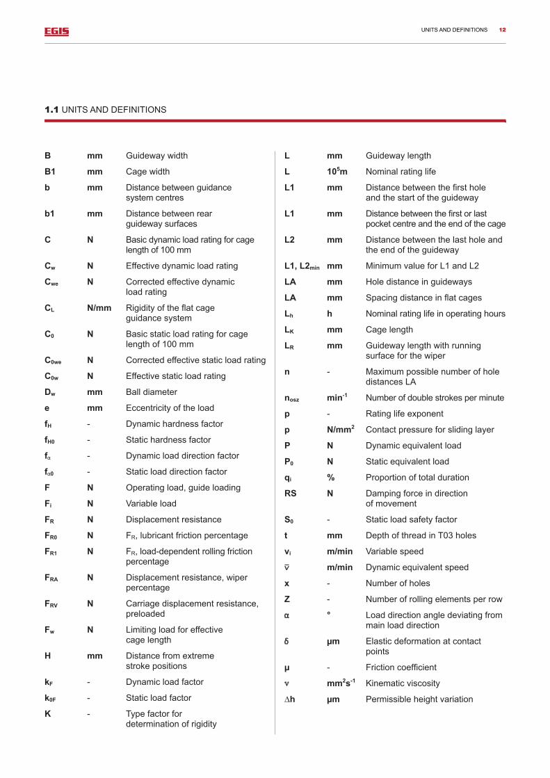
1.1 UNITS AND DEFINITIONS
B mm Guidewaywidth
B1 mm Cagewidth
b mm Distancebetweenguidance systemcentres
b1 mm Distancebetweenrear guidewaysurfaces
C N Basicdynamicloadratingforcagelengthof100mm
Cw N Effectivedynamicloadrating
Cwe N Correctedeffectivedynamic loadrating
CL N/mm Rigidityoftheflatcage guidancesystem
C0 N Basicstaticloadratingforcagelengthof100mm
C0we N Correctedeffectivestaticloadrating
C0w N Effectivestaticloadrating
Dw mm Balldiameter
e mm Eccentricityoftheload
fH - Dynamichardnessfactor
fH0 - Statichardnessfactor
f - Dynamicloaddirectionfactor
f 0 - Staticloaddirectionfactor
F N Operatingload,guideloading
Fi N Variableload
FR N Displacementresistance
FR0 N FR,lubricantfrictionpercentage
FR1 N FR,load-dependentrollingfrictionpercentage
FRA N Displacementresistance,wiperpercentage
FRV N Carriagedisplacementresistance, preloaded
Fw N Limitingloadforeffective cagelength
H mm Distancefromextreme strokepositions
kF - Dynamicloadfactor
k0F - Staticloadfactor
K - Typefactorfor determinationofrigidity
L mm Guidewaylength
L 105m Nominalratinglife
L1 mm Distancebetweenthefirsthole andthestartoftheguideway
L1 mm Distancebetweenthefirstorlastpocketcentreandtheendofthecage
L2 mm Distancebetweenthelastholeandtheendoftheguideway
L1, L2min mm MinimumvalueforL1andL2
LA mm Holedistanceinguideways
LA mm Spacingdistanceinflatcages
Lh h Nominalratinglifeinoperatinghours
LK mm Cagelength
LR mm Guidewaylengthwithrunning surfaceforthewiper
n - MaximumpossiblenumberofholedistancesLA
nosz min-1 Numberofdoublestrokesperminute
p - Ratinglifeexponent
p N/mm2 Contactpressureforslidinglayer
P N Dynamicequivalentload
P0 N Staticequivalentload
qi % Proportionoftotalduration
RS N Dampingforceindirection ofmovement
S0 - Staticloadsafetyfactor
t mm DepthofthreadinT03holes
vi m/min Variablespeed
m/min Dynamicequivalentspeed
x - Numberofholes
Z - Numberofrollingelementsperrow
° Loaddirectionangledeviatingfrommainloaddirection
µm Elasticdeformationatcontactpoints
µ - Frictioncoefficient
mm2s-1 Kinematicviscosity
Δh µm Permissibleheightvariation
12

Q10
Q6
Q2
Guideway length
Per
mis
sibl
e de
viat
ion
in µ
m
PRECISION AND TOLERANCES
1.2 PRECISION AND TOLERANCES
1.2.1 QUALITIES
Theracewaysandlocatingsurfacesareprecision-ground.
Theguidewaysaresuppliedin3qualities(parallelismtoleranceoftheracewaystothereferencesidesoftheguidewayinrelationtoadefinedlength).
Q10:normalqualityforgeneralmachineconstruction
Q6: precisequalityformachinetoolconstruction
Q2: particularlyprecisequalityforexceptionallydemandingstructures
1.2.2 PROFILE TOLERANCES
Seeproductchapter
1.2.3LENGTHS,HOLEDISTANCES
Length:thelengthtoleranceisdefinedusingtheformula ±[0.2+(0.0012*lengthL)].
Guidewayswhichexceedthemaximumlengthindicated (see“normallengths”table)aremanufacturedinseveralsections.Thesesectionsarematchedprecisely.Itisimportantnottointerchangetheguidewaysinordertomaintainthetoleranceduringassembly.
Hole distances:thetoleranceoftheholedistancesiscalculatedtoensurethatguidewayscanbeassembledonapre-drilledholepatternuptothemaximumnormallength.Thetoleranceismeasuredbetweenthefirstandlastguidewayholeandisdistributedevenlyoverthelength.
Forguidewayswhichexceedthemaximumnormallength,thesuffix“P”isrequiredinordertomaintainthecorrespondingtolerance.
13

PRECISION AND TOLERANCES
1.2.4 MATCHING
Guidewaysofthesamedesign(sameorderreference)aremanufactured,labelledandpackedinpairs.Pairedmatch-ingisbasedonthedistancebetweenthecentreoftheprofileandthemountingsurface“A”.
Standardmatching(US1/US2)allowspartstobeexchangedwhilstmaintainingaverynarrowtolerance.Inthehighesttolerancecategoryoratthecustomer’srequest,theguidewaysarematchedandlabelledbymorenarrowtolerances.
Forguidewayswithdifferentorderreferenceswhichstillhavetobematchedinpairs,thesuffix“X”hastobeaddedtotheorderreferences,e.g.
1M+1ML=2SXor1M+1V+1J+1S=4SRXor1V…T15+1V…T03=2SX
Matchingpossibilities:
14

PRECISION AND TOLERANCES
1.2.5 STRAIGHTNESS
Straightnessaswellasparallelismischeckedinthefactory(tolerancesaccordingtoDIN644).
Straightnessvariancescanbebalancedoutbytighteningagainstthelocatingsurfaceduringassembly.
1.2.6 ROLLING ELEMENTS
Flatcageassembliescompriseneedleorcylindricalrollerswithadiametertoleranceof2µmandageometricalaccuracyof1µm.
Forparticularlychallengingrequirements,especiallyforguidewayswithaqualitylevelof2,speciallydesignedneedleorcylindricalrollerscanbesuppliedwithadiameter toleranceof1µmandageometricalaccuracyof0.5µm.
Thediametertoleranceamountsto1µmandthegeometricalaccuracy0.13µmforballbearings.
Seetable(page76),inchapter8onflatcageassemblies.
Paired matching code Number of guideways matched together In relation to reference side
2SA 2 ReferencesideA
3SA 3 ReferencesideA
4SA 4 ReferencesideA
etc… Numberofguideways ReferencesideA
2SR 2 ReferencesideR
3SR 3 ReferencesideR
4SR 4 ReferencesideR
etc… Numberofguideways ReferencesideR
2SAR 2 ReferencesidesA+R
3SAR 3 ReferencesidesA+R
4SAR 4 ReferencesidesA+R
etc… Numberofguideways ReferencesidesA+R
15

APPLICATION FEATURES
1.3 APPLICATION FEATURES
1.3.1 CHOICE OF ARRANGEMENT TYPE
Closed layout M/V
Thislayoutcancarryloadsandmomentsinanydirec-tion,canbeadaptedtoanyoperatingpositionandcanbepreloaded(preloadingpage34).
Itisalocating/locatingbearingandconsistsoftwoM/MLandtwoVguidewayswiththecorrespondingangledflatcageassemblies.
Open layout
Thislayoutisextremelyassembly-friendlyandismainlyusedforapplicationswithloadsactingcentricallyorvertically. Itisalocating/non-locatingbearingandconsistsofMandVguidewayswiththecorrespondingangledflatcageassemblyandJandSguidewayswiththecorre-spondingflatcageassembly.
Closed layout LUE
Thislayoutcancarryloadsandmomentsinanydirec-tioninresponsetothemostdemandingprecisionsrequirements.Thesystemispreloadedbycomponentswhichhavebeenadjustedagainstoneanotherintermsofdimensions.
Thesubdivisionintolocatingandnon-locatingbearingspreventsthesystemfrombecomingdistortedbythermalexpansion.TheguidancesystemconsistsofMandVguideways,JandSguideways,LUcounterstays,angledflatandflatcageassemblies.
Figure1.ClosedlayoutM/V
Figure2.OpenlayoutM/V,J/S
Figure3.ClosedlayoutLUE
16
APPLICATION FEATURES
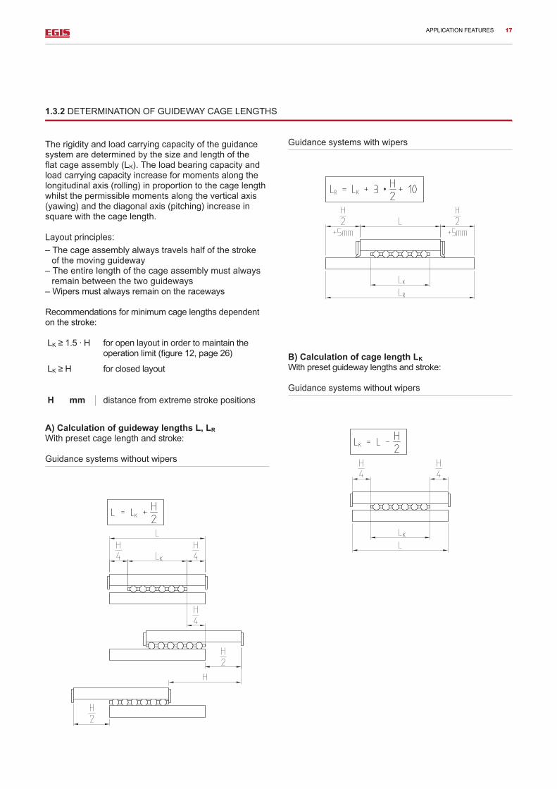
Guidancesystemswithwipers
B) Calculation of cage length LK Withpresetguidewaylengthsandstroke:
Guidancesystemswithoutwipers
1.3.2 DETERMINATION OF GUIDEWAY CAGE LENGTHS
Therigidityandloadcarryingcapacityoftheguidancesystemaredeterminedbythesizeandlengthoftheflatcageassembly(LK).Theloadbearingcapacityandloadcarryingcapacityincreaseformomentsalongthelongitudinalaxis(rolling)inproportiontothecagelengthwhilstthepermissiblemomentsalongtheverticalaxis(yawing)andthediagonalaxis(pitching)increaseinsquarewiththecagelength.
Layoutprinciples:
–Thecageassemblyalwaystravelshalfofthestroke ofthemovingguideway
–Theentirelengthofthecageassemblymustalwaysremainbetweenthetwoguideways
–Wipersmustalwaysremainontheraceways
Recommendationsforminimumcagelengthsdependentonthestroke:
LK≥1.5·H foropenlayoutinordertomaintaintheoperationlimit(figure12,page26)
LK≥H forclosedlayout
H mm distancefromextremestrokepositions
A) Calculation of guideway lengths L, LR Withpresetcagelengthandstroke:
Guidancesystemswithoutwipers
17

Special length ratios:
Ifthelengthsareconfiguredaccordingtotheequationsabove,theflatcageassemblywillbeineverystrokepositionbetweentheraceways.
Inordertoachievethemaximumloadcarryingcapac-ityorasignificantstroke,thelengthscanbeconfiguredundernormaloperatingconditionsinsuchawaythattheflatcageassemblyextendsbeyondtheendsoftheguideways.Racewayleadareasshouldbeprovidedinthiscase(suffixE2).
1.3.3 HOLE TYPES AND HOLE PATTERNS
Guidewaysareattachedwithscrews.EGISguidewaysaresuppliedwith4holetypes(figure4).
EGISguidewaysofstandardlengthsintheMandVrangesarehardenedandpre-groundwithT15sinkholes. ByaddingESMinsertnuts,theseguidewayscanbeattachedinthesamemanneraswithathreadedhole(T03,figure5).
Theinsertnutsmustbeorderedseparatelyandstuckintothecounterbores(T13,accessories,page91).
Figure4.Holetypes
Figure5.AttachmentwithholetypeT13
Guidancesystemswithwipers:
Thenecessarycagesizecanbeselectedonthebasisofloadandrigidityparameters.
APPLICATION FEATURES 18
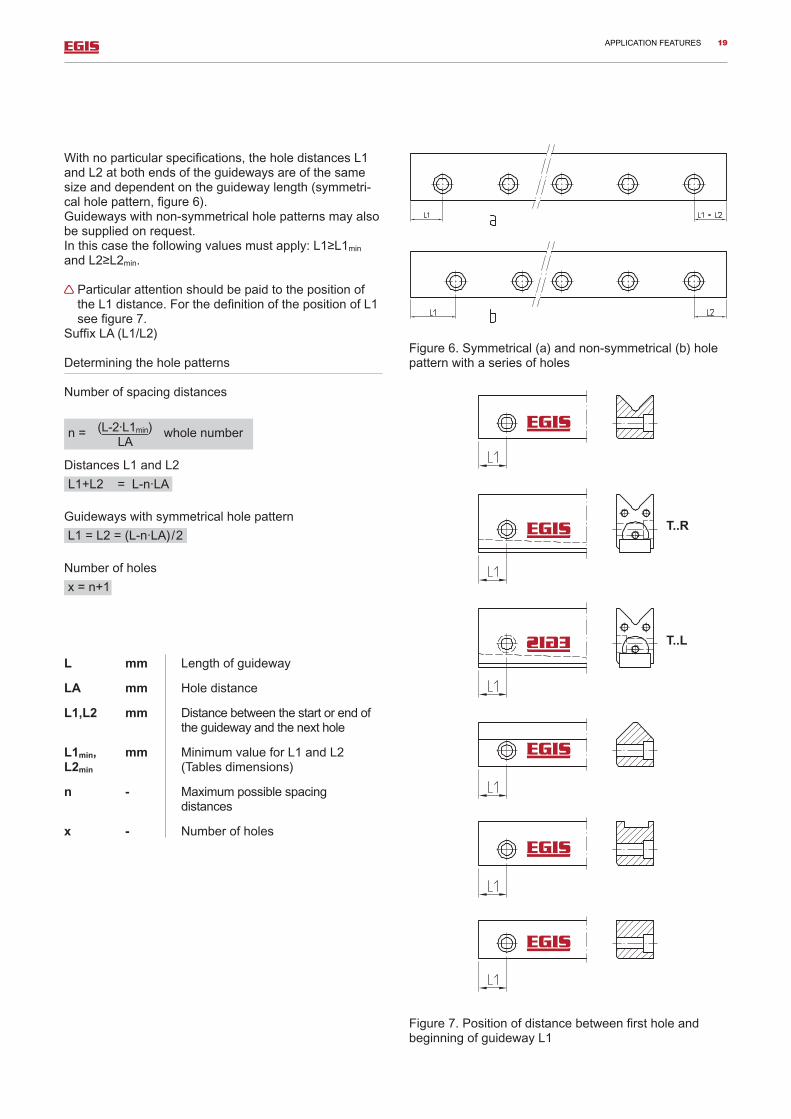
Withnoparticularspecifications,theholedistancesL1andL2atbothendsoftheguidewaysareofthesamesizeanddependentontheguidewaylength(symmetri-calholepattern,figure6).Guidewayswithnon-symmetricalholepatternsmayalsobesuppliedonrequest.Inthiscasethefollowingvaluesmustapply:L1≥L1min andL2≥L2min.
ParticularattentionshouldbepaidtothepositionoftheL1distance.ForthedefinitionofthepositionofL1seefigure7.
SuffixLA(L1/L2)
Determiningtheholepatterns
Numberofspacingdistances
DistancesL1andL2
Guidewayswithsymmetricalholepattern
Numberofholes
L mm Lengthofguideway
LA mm Holedistance
L1,L2 mm Distancebetweenthestartorendoftheguidewayandthenexthole
L1min, mm MinimumvalueforL1andL2L2min (Tablesdimensions)
n - Maximumpossiblespacing distances
x - Numberofholes
Figure6.Symmetrical(a)andnon-symmetrical(b)holepatternwithaseriesofholes
Figure7.PositionofdistancebetweenfirstholeandbeginningofguidewayL1
(L-2·L1min)LA
n= wholenumber
L1+L2=L-n·LA
L1=L2=(L-n·LA)/2
x=n+1
T..R
T..L
APPLICATION FEATURES 19
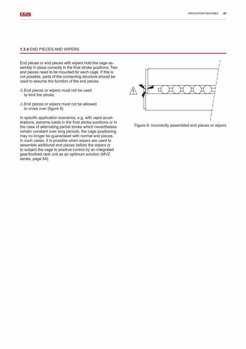
1.3.4 END PIECES AND WIPERS
Endpiecesorendpieceswithwipersholdthecageas-semblyinplacecorrectlyinthefinalstrokepositions.Twoendpiecesneedtobemountedforeachcage.Ifthisisnotpossible,partsoftheconnectingstructureshouldbeusedtoassumethefunctionoftheendpieces.
Endpiecesorwipersmustnotbeused tolimitthestroke.
Endpiecesorwipersmustnotbeallowed tocrossover(figure8)
Inspecificapplicationscenarios,e.g.withrapidaccel-erations,extremeloadsinthefinalstrokepositionsorinthecaseofalternatingpartialstrokewhichneverthelessremainconstantoverlongperiods,thecagepositioningmaynolongerbeguaranteedwithnormalendpieces.Insuchcases,itispossiblewhenwipersareusedtoassembleadditionalendpiecesbeforethewipersortosubjectthecagetopositivecontrolbyanintegratedgear/toothedrackunitasanoptimumsolution(MVZseries,page54).
Figure8.Incorrectlyassembledendpiecesorwipers
APPLICATION FEATURES 20

1.3.5LOADRATING,LOADCARRYINGCAPACITY
Thedynamicandstaticloadratingsareusedasareferenceforthelayoutofaflatcageguidancesystem.Theloadratingsforlinearguidancesystemswithoutrecirculatingrollingelementsaredefinedaccording totheISO14728internationalstandard.
1.3.5.1 bASIC STATIC LOAD RATING
ThebasicstaticloadratingsC0aretheloadswhichbringapermanentdeformationoftheracewaysandrollingele-mentsinatenthousandthoftherollingelementdiameter.
Static load safety factor
ThestaticloadsafetyfactorS0isthesecurityinrelationtothepermanentdeformationintherollingcontact.
S0 Staticloadsafetyfactor
C0w N Effectivestaticloadrating(page24)
P0 N Maximumstaticequivalentload
Particularattentionshouldbepaidtotheloadsafetyfactor.
AccordingtoISO14728,thestaticsafetyS0 = C0/P0mustnotfallbelowthevalueof2.
Ifstrictrequirementsapplyintermsoftherunningaccu-racyandsmoothness,thestaticloadsafetyfactorshouldnotfallbelowS0 = 3.
1.3.5.2 STATIC LOAD CARRYING CAPACITY
Thepermissiblestaticloadforaflatcaseguidancesys-temislimitedbythefollowingcharacteristics:
– Basicstaticloadratingoftheflatcageassemblies: recommendationsforS0shouldbeobserved.
– Loadcarryingcapacityoftheraceways: requiredhardnessHRC58min.
– Loadcarryingcapacityoftheconnectingstructure:theconnectingstructureisgenerallyconfiguredwithahighdegreeofrigidityandthereforesufficientstrength.
–Loadcarryingcapacityofthescrewconnection: thelayoutoftheguidewayattachmentisbasedonthescrewstrength8.8andthecorrespondingtighteningtorquetakingthestandardmaterialsfortheconnectingstructureintoaccount.Screwsofthislevelofstrengthallowforthetransferralofloadswhilstscarcelyaffec-tingtheprecisionoftheguidancesystem.
Whenscrewsofahigherstrengthcategoryareused,thetighteningtorqueaccordingtothestrengthcategory8.8shouldnotbeexceededintheinterestofaccuracy(exception:LUEsystemcounterstay,seepage73).
Itisimportanttocheckthescrewconnectionwhere S0<3whentensileand/ormomentloadsarepredo-minant.
C0w
P0S0 =
APPLICATION FEATURES 21

1.3.5.4 DYNAMIC LOAD CARRYING CAPACITY AND RATING LIFE
Thedynamicloadcarryingcapacityisdeterminedbythefatiguebehaviourofthebearingcomponents.Thefatigueperiod(theratinglifeinhours)isobtainedfromtheloadandthemovementspeedoftheguidancesystemaswellasthestatisticalprobabilityofdamageoccurring.
Nominalratinglife
L 105 m Nominalratinglife
Lh h Nominalratinglifeinoperatinghours
Cw N Effectivedynamicloadrating(p.24)
P N Dynamicequivalentload
p - Ratinglifeexponent
Forflatcageguidancesystemswithrollers:p=10/3 Forflatcageguidancesystemswithballs:p=3
H mm Distancefromextreme strokepositions
nosz min-1 Numberofdoublestrokesperminute
m/min Dynamicequivalentspeed
AccordingtoISO14728,thedynamicequivalentloadmustnotexceedthevalueP=0.5·CW.
1666
Cw
P
pLh =
Cw
P
pL =
8.33 105
HnoszCw
P
pLh =
1.3.5.3 bASIC DYNAMIC LOAD RATING
ThebasisforthebasicdynamicloadratingCisthenominalratinglifeof100,000mdisplacementdistanceobtainedorexceededwithareliabilityof90%.
LOADRATING,LOADCARRYINGCAPACITY
APPLICATION FEATURES 22
q1· v1+q2·v2+...+qz·vz100
=
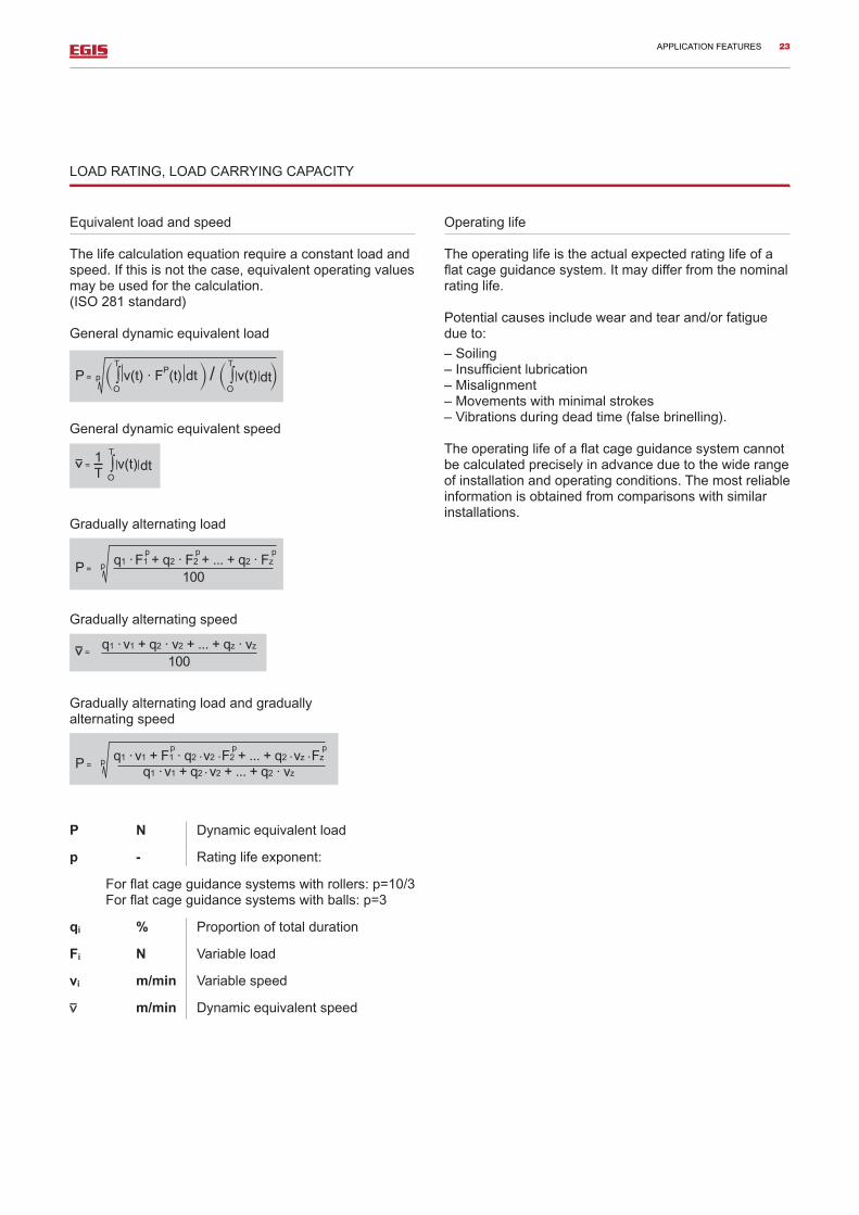
Equivalentloadandspeed
Thelifecalculationequationrequireaconstantloadandspeed.Ifthisisnotthecase,equivalentoperatingvaluesmaybeusedforthecalculation. (ISO281standard)
Generaldynamicequivalentload
Generaldynamicequivalentspeed
Graduallyalternatingload
Graduallyalternatingspeed
Graduallyalternatingloadandgradually alternatingspeed
P N Dynamicequivalentload
p - Ratinglifeexponent:
Forflatcageguidancesystemswithrollers:p=10/3 Forflatcageguidancesystemswithballs:p=3
qi % Proportionoftotalduration
Fi N Variableload
vi m/min Variablespeed
m/min Dynamicequivalentspeed
Operatinglife
Theoperatinglifeistheactualexpectedratinglifeofaflatcageguidancesystem.Itmaydifferfromthenominalratinglife.
Potentialcausesincludewearandtearand/orfatiguedueto:
–Soiling–Insufficientlubrication–Misalignment–Movementswithminimalstrokes–Vibrationsduringdeadtime(falsebrinelling).
Theoperatinglifeofaflatcageguidancesystemcannotbecalculatedpreciselyinadvanceduetothewiderangeofinstallationandoperatingconditions.Themostreliableinformationisobtainedfromcomparisonswithsimilarinstallations.
P=p∫ v(t)·FP(t) dt/∫ v(t) dtT T
O O
1T
q1· F1+q2·F2+...+q2·Fz100
P =
LOADRATING,LOADCARRYINGCAPACITY
q1· v1 + F1·q2v2 F2+...+q2vz Fz
q1· v1+q2v2+...+q2·vzP =
APPLICATION FEATURES 23

1.3.5.5 EFFECTIVE LOAD RATING
ThebasicdynamicandstaticloadratingsCandC0givenforthedifferentproductsrelatetoacagewithatheoreticallengthof100mm.Thisallowsdirectcomparisonstobemadebetweentheloadcarryingcapacitiesofflatcagesofdifferentseriesanddimensions.TheeffectivedynamicandstaticloadratingsCwandC0warecalculatedaccordingtothefollowingequationsfortheeffectivecagelengths.
Forneedlerollerflatcageassemblies:
Forballflatcageassemblies:
C N Basicdynamicloadratingforacagelengthof100mm(tabledimensions)
C0 N Basicstaticloadratingforacagelengthof100mm(tabledimensions)
Cw N Effectivedynamicloadrating
C0w N Effectivestaticloadrating
LK mm Cagelength(figure9)
L1 mm Distancebetweenthefirstandlastpocketcentreandtheendofthecage(figure9)
LA mm Spacingdistanceintheflatcage(figure9,tabledimensions)
ThevaluesforC0wandCwcorrespondtotheloadratingcalculationaccordingtoISO14728
TheequationsonlyprovidepreciseresultswhenthecagelengthLkisbasedonawholenumberofrollingelementsperrow.
EquationforverificationofZ:
Z-numberofrollingelementsperrow(figure9)
Figure9.Dimensionstodeterminetheeffectiveloadrating
Cw = C LK - 2L1 + LA100
34
1 36 LK - 2L1
100 - LA
Cw = C LK - 2L1 + LA100
23
1 36 LK - 2L1
100 - LA
C0w = C0LK - 2L1 + LA
100
C0w = C0LK - 2L1 + LA
100
Z = LK - 2L1
LA+1 = wholenumber
APPLICATION FEATURES 24
1
0.9
0.8
0.70 5 10 15 20 25 30 35 40 45
1
0.9
0.8
0.7
0.6
0.5
0.4
0.3
0.2
0.1
070060.1
65057.8
60055.2
55052.3
50049.1
45045.3
40040.8
35035.5
30029.8
25022.2
200-
HVHRC
hardness
fH0
fH
fH0 roller
fH0 ball
fH
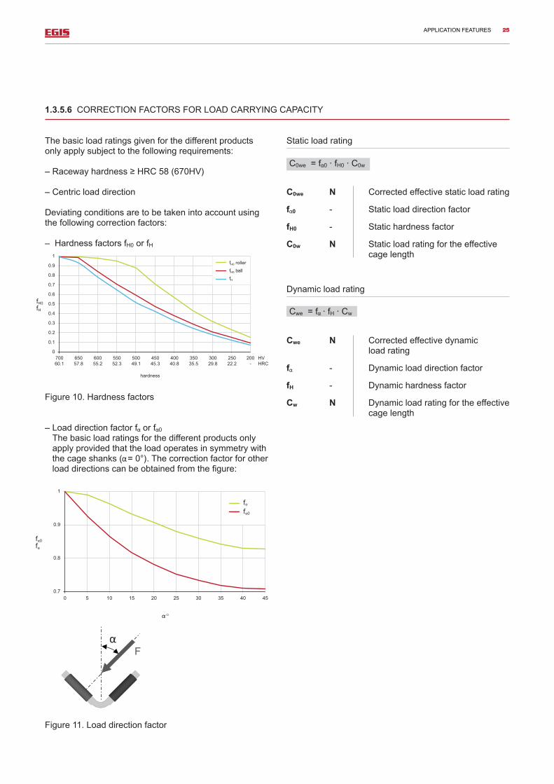
Thebasicloadratingsgivenforthedifferentproductsonlyapplysubjecttothefollowingrequirements:
–Racewayhardness≥HRC58(670HV)
–Centricloaddirection
Deviatingconditionsaretobetakenintoaccountusingthefollowingcorrectionfactors:
–HardnessfactorsfH0orfH
Figure10.Hardnessfactors
–Loaddirectionfactorf orf 0 Thebasicloadratingsforthedifferentproductsonlyapplyprovidedthattheloadoperatesinsymmetrywiththecageshanks( =0°).Thecorrectionfactorforotherloaddirectionscanbeobtainedfromthefigure:
Figure11.Loaddirectionfactor
Staticloadrating
C0we N Correctedeffectivestaticloadrating
f 0 - Staticloaddirectionfactor
fH0 - Statichardnessfactor
C0w N Staticloadratingfortheeffectivecagelength
Dynamicloadrating
Cwe N Correctedeffectivedynamic loadrating
f - Dynamicloaddirectionfactor
fH - Dynamichardnessfactor
Cw N Dynamicloadratingfortheeffectivecagelength
1.3.5.6 CORRECTION FACTORS FOR LOAD CARRYING CAPACITY
C0we=f 0·fH0·C0w
Cwe=f ·fH·Cw
APPLICATION FEATURES 25

5
4.5
4
3.5
3
2.5
2
1.5
10 0.05 0.10
0.167
0.15 0.20 0.25 0.3 0.35 0.4
Relative load eccentricity e/LK
kOF
1.3.5.7 ECCENTRIC LOAD
Inalinearguidancesystemwithoutrecirculatingrollingelements,theflatcagealwaystravelshalfthestrokeofthemobileguidewayandthusaltersitspositioninrelationtotheload.Itthereforedoesnotgenerallycarryanequalload.However,theloadratingsgivenforthedifferentproductsonlyapplywithanequalloaddistribution.
Eccentricloadwithopenlayout
Openlayout:seeapplicationfeatures(page16,figure2)Inthecaseofaneccentricload,theloadcarryingcapac-itycanbedeterminedwiththestaticequivalentcageload(figure12).
P0 N Staticequivalentload
k0F - Staticloadfactor
F N Guideloading
Figure12.Staticloadfactorforeccentricallyloadedflatcagesandopenlayout
Ifaloadeccentricityof>0.167isexceeded,onlypartoftherollingelementisloaded.Thisisextremelydetri-mentaltotheloadcarryingcapacityandrigidityoftheguidancesystem.
P0 = k0F·F
Eccentricloadwithclosedlayout
Closedlayout:seeapplicationfeatures,(page16,figure1)
Linearguidancesystemswithaclosedlayoutcancarry additionalloadsandtiltingmoments.Inthesecases,thecalculationoftheequivalentcageloadisfairlycomplex.EGISofferssupportwithcorrespondingcalculationpro-grammesonrequest(pages28to31).
APPLICATION FEATURES 26

Example
Inputdata
Guideways M5025andV5025
Flatcageassembly E-HW15
Basicdynamicloadratingfora C =25960N
cagelengthof100mm
Basicstaticloadratingfora C0 =88900N
cagelengthof100mm
Operatingload,functioning F =9500N
centricallyontheguidancesystem
(factorsf ,f 0,k0F=1)
Dynamicequivalentload P =9500N
Staticequivalentload P0 =9500N
Distancefromextreme H =100mm
strokepositions
Numberofdoublestrokes nosz =50min-1
perminute
Cagelength LK =300mm
Requireddata
Staticloadsafetyfactor S0
Nominalratinglife LandLh
Calculation
Verificationofnumberofrollingelementsperrow (LA,L1,dimensiontables)
Forcalculation:
Effectivestaticloadrating
StaticloadsafetyfactorSo
EffectivedynamicloadratingCw:
NominalratinglifeL:
NominalratinglifeLh
1.3.5.8 CALCULATION
Z = +1LK - 2L1LA
C0w = C0 ·LK - 2L1 + LA
100
C0w = 88900· = 264000 N297100
S0 = C0w
P0S0 = = 27.8264000
9500
Z= +1 = 66300 - 74.5
Cw =C· ·¾ 1/36
LK - 2L1 + LA100
LK - 2L1100 - LA
L =10/3
Cw
PL = =472·105
10/3602509500
LK=(Z-1) · LA+2L1=299.5mm
Cw =25960· ·¾ 1/36
295100
28895.5
= 60250 N
Lh = ·10/3
Cw
P8.33·10H·nosz
Lh = ·472=78600h8.33·10100·50
APPLICATION FEATURES 27

X
Y
Z Mz
My Mx
xi
yi zi
Fzi Fxi Fyi
O
Thecalculationonpages21to27canbeusedtoestab-lishaninitiallayoutforflatcageguidancesystems.Theequationsarebasedonadefinedstaticsystem.Inpractice,however,anundefinedstaticsystemisgen-erallyused.Thisdoesnotallowforsimplecalculations;inordertoobtainaprecisecalculation,thepreloadandinternalloaddistributionhavetobetakenintoaccount.TheloadcarryingcapacityandrigidityfordifferentloadscanbecalculatedusingacorrespondingEGIScalcula-tionprogramme.
Thecalculationprogrammedeterminesthefollowingdata:
–Staticloadsafetyfactor–Displacementstemmingfromtheelasticityofthebearing.
Thenon-lineardeflectionoftherollingelementsistakenintoaccountinthiscontext.Theconnectingstructureisassumedtoberigid.
Thefollowingdetailsarerequiredforthecalculationofeveryloadscenario(figure14anddatasheet,page29):
–Sizeandpositionoftheelementsoftheguidancesystem–Positionofthedriveaxis–Positionoftheloadingpointandexternalloadcomponents–Shear-freemoments–Positionofthebalancepointsandsizeofweights–Kineticvalves–Durationofparticularsteps
Thegeometryandloadscanbedescribedsimplyusingthefollowingdatasheet.Aright-handedcoordinatesystemisusedforthede-scription.Theright-handruleappliesformoments.
Positionofco-ordinateorigin:
–Carriagesincentralstrokeposition–x:centreofbearingcagelength–y:centreplaneofguideways–z:centralbetweentheguideways
Oneormorestrokepositionsdeviatingfromthecentralpositionmaybeusedforthecalculation.
Thedataenteredinthedatasheetcorrespondtotheguidancesystempresentedinfigure15asanexample.
Calculationprogramme
Figure13.Internalloaddistributioninthecaseofloadsproducedbyloadsandmoments
Figure14.Coordinatesystem
APPLICATION FEATURES 28

Project : Example
Guidance system : Horizontal drilling carriage
Guidance geometry Guideway size 4020Cage length LK 200 mm
Distance between rear guideway surfaces b1 145 mm
Installation layout XIStroke H 110 mm
Position of drive axis yA -‐32 mm
zA 30 mm
Load case No./ description Nr. 1 Drilling
Carriage position(s) for the calculation xB 50 mm
Speed v 3 m/min
Duration of particular step q 50 %
xi yi zi Fxi Fyi Fzi Mxi Myi Mzi
mm mm mm N N N Nmm Nmm Nmm1 195 -90 0 -1200 -20000
2 55 -40 0 800
3
4
5
6
7
8
9
10
11
12
13
14
15
Moments Point i
Description Coordinates Loads, components
Drilling tool: drilling pressure, torque
Carriage + shaft weight
Datasheet
APPLICATION FEATURES 29

x z
Y
A
1
2
Antrieb
x
z Y
Fx1
Mx1
1
X1
zA
//
//
Lk
2
x z
Y
X2 y2
Fy2
Y1 Fx1
Mx1 1
Antrieb
YA
x z
Y
A
1
2
Antrieb
x
z Y
Fx1
Mx1
1
X1
zA
//
//
Lk
Example:horizontaldrillingcarriage
Figure15.Geometryandloaddetails
Xlayout,internalcarriage Xlayout,externalcarriage
XI XA
OI OA
Olayout,internalcarriage Olayout,externalcarriage
Installationlayout
APPLICATION FEATURES
Drive
Drive
30

Example:horizontaldrillingcarriage
Results
Poweroncarriagedrive Fx = -1200 NResultingloadonguidancesystem: Fy = 800 N Fz = 0 N Mx = -20000 Nmm My = -36000 Nmm Mz = -82400 Nmm
Requiredpreloadpower Pv = 3050 N
Percentagerateofstaticloadcarryingcapacity C0: 2.54%
Displacementoftheguidancesystem: del y = 0.13992 µm del z = -0.00719 µm phi x = -0.00152 mrad phi y = -0.00389 mrad phi z = -0.00863 mrad
Staticloadsafetyfactor: S0 = 31.6
Displacementatpointi(µm) Nr. del ix del iy del iz
1 -0.27622 0.18561 0.04155 2 -0.77686 -1.54327 0.88915 3 -0.34527 -0.33483 0.26788
Thecalculateddisplacementsonlyincludetheeffectofthedeflectionofrollingelementsandraceways.Thedeformationoftheconnectingstructureisnottakenintoaccount.
APPLICATION FEATURES 31
100
90
80
70
60
50
40
30
20
10
0
0
1000
2000
3000
4000
5000
6000
7000
8000
9000
10'0
00
11'0
00
12'0
00
13'0
00
14'0
00
15'0
00
16'0
00
17'0
00
Load F (N)
BallØ 9
RollerØ 9 x 9
3 needle rollersØ 3 x 9
Def
lect
ion
δ (µ
m)
F
F
F
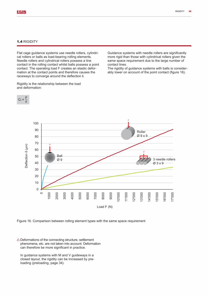
Flatcageguidancesystemsuseneedlerollers,cylindri-calrollersorballsasload-bearingrollingelements.Needlerollersandcylindricalrollerspossessalinecontactintherollingcontactwhilstballspossessapointcontact.TheoperatingloadFcreatesanelasticdefor-mationatthecontactpointsandthereforecausestheracewaystoconvergearoundthedeflection .
Rigidityistherelationshipbetweentheload anddeformation:
Guidancesystemswithneedlerollersaresignificantlymorerigidthanthosewithcylindricalrollersgiventhesamespacerequirementduetothelargenumberofcontactlines.Therigidityofguidancesystemswithballsisconsider-ablyloweronaccountofthepointcontact(figure16).
Deformationsoftheconnectingstructure,settlementphenomena,etc.arenottakenintoaccount.Deformationcanthereforebemoresignificantinpractice.
InguidancesystemswithMandVguidewaysinaclosedlayout,therigiditycanbeincreasedbypre-loading(preloading,page34).
1.4 RIGIDITY
CL = F
Figure16.Comparisonbetweenrollingelementtypeswiththesamespacerequirement
RIGIDITY 32

Therigidityisdependentontheloadand thenumberandgeometryoftherollingelements.
Flatcageguidancesystemswithlinecontact
Flatcageguidancesystemswithpointcontact
µm Elasticdeformationatthecontactpoints,convergenceofthetworacewaylevels
K - Factorforthedeterminationof elasticdeformationdependent ofthetype(table17)
F N Operatingload
Z - Numberofrollingelementsperrow
Lw mm Rollingelementlength
CL N/µm Rigidityoftheflatcageguidancesystem
DW mm Balldiameter.
Table17:factorKforthedetermination ofelasticdeformation
CL =1/K·F0.1·Z0.9 · Lw0.8
CL =1/K·F1∕3 ·Z2∕3 · Dw1∕3
=K·(F/Z)0.9/ Lw0.8
=K·(F/Z) 2∕3 / Dw1∕3
Calculationexample
Guideway M5025andV5025Flatcageassembly E-HW15x300Operatingload F=9500NNumberofrollingelementsperrow Z=66Rollingelementlength Lw=6.8mmTypefactor(table) K=0.0822
Elasticdeformationcalculation:
=0.0822·(9500/66)0.9/6.8 0.8=1.6µm
Rigiditycalculation:
CL=1/0.0822·95000.1·660.9·6.80.8=6100N/µm
=K·(F/Z)0.9/Lw0.8
CL=1/K·F0.1·Z0.9·Lw0.8
GuidewayType FactorK GuidewayType FactorK
0.0822
0.0794
0.0426
0.8776
RIGIDITY 33

Thepreloadofflatcageguidancesystemscanbeusefulforthefollowingreasons:
–Increaseofrigidity–Improvementofrunningaccuracy–Improvementofloaddistributionandreduction ofmaximumloadontheouterrollingelements
–Increaseofpermissiblemoments
Thepreloadinfluencesthedisplacementresistanceandratinglife.
Referencevalueforthepreload:2to3%ofC0.TheoptimumpreloadforconcreteloaddatascanbedeterminedusingEGIScalculationprogrammes.
Anoptimumpreloadreducesthepossibilityofuncontrolledmovementintheflatcageassembly(cageroaming).
Inordertoguaranteethattherigidityofourlinearguidancesystemsisfullyoptimised,caremustbetakentoensurethattheconnectingstructureissufficientlyrigidandprecise.
Inthecaseofimpreciseconnectingstructuresoroneswhichcanbeeasilydeformed,angleerrorsmayoccurbetweentheracewayswhichcreateanincreasedloadattheendsoftherollingelements.
Thiswouldnotresultinincreasedrigiditybutrathertheendloadwouldreducetheoperatinglife.
1.5 PRELOAD
1.5.1 SETTING THE PRELOAD
Thepreloadcanbemeasuredandsetusingdifferentmethods:
–usingpressurescrewswithasettingtorqueaccordingtothetableonpage35
–bymeansofFRVcarriagedisplacementresistance (seebelow)
–bymeasuringthedeformationoftheconnectingstructure.
FRV N Carriagedisplacementresistance
C0w N Effectivestaticloadrating
Requirements:
–Preload2,5%C0
–Lubricatedguidancesystemwithoutoperatingload–Movementatapprox.0,05m/s
FRV = C0w
40'000
PRELOAD 34

1.5.1.1 PRESSURE SCREWS
Inthecaseofsmallloads(S0>5)theguidancesystemcanbepreloadedbymeansofpressurescrews.Asmallereffectivespancanbeobtainedbyinsertingthepressurescrews(studscrewsaccordingtoISO4026,DIN913)betweentheattachmentscrewsandattheendoftheguideway(table18,figure19).
1)Torqueforapreloadof2,5%C0
Figure19.Positionofthepressurescrews
1.5.1.2 GUIDEWAYS WITH ADJUSTING GIb
TheuseofMLguidewayswithanadjustinggibisrecom-mendedwhereahighdegreeofrigidityisrequiredorwithlargerloads(S0<5).Thisensuresthatthepreload isdistributedevenlyovertheentireguidewaylength.
Guideways Flat cage assemblyPressure screw Setting torque
Dimension Distance / mm ME1) / Nm
M/V3015 E-HW10 M4 40 0.34
M/V4020 E-HW15 M6 80 1.2
M/V5025 E-HW16 M6 80 1.8
M/V4525 E-HRW50 M6 80 1
M/V6035 E-HW20 M8 100 2.9
M/V6535 E-HRW70 M8 100 3.5
M/V7040 E-HW25 M10 100 5.7
M/V8050 E-HW30 M12 100 7.7
TABLE18.PRESSURESCREWS/SETTINGTORQUE
PRELOAD 35

LUbRICATION
1.6.1 LUbRICANTS
Greaseoroilcanbeusedaslubricants.Thechoiceoflubricationprocedureismadeonthebasisoftechnicalandeconomicconsiderations:
Advantagesoflubricationwithgrease:
–longrelubricationintervals–reducedstructuralexpenditurewhenrelubrication isnotrequired
–thickenerinthegreasecreatesemergency operationfeatures
–supporttotheseal
Advantagesoflubricationwithoil:
–excellentlubricationapplication–dirtisflushedout–heatisdissipated
Flatcageguidancesystemsonlyrequireminimallubrica-tion.Theyaresuppliedwithapreservative.Thepreserv-ativeiscompatiblewithgreaseandoils.
Flatcageguidancesystemsaregenerallyoperatedinareasofmixedfriction.Forthisreason,dopedlubricantswithhigh-pressureadditivesshouldbeused(codeletterPaccordingtoDIN51502).
Coolinglubricantsmustnotbeusedastheythinoutthelubricantsandcancausecorrosion.Lubricantswithsolidadditivesmustnotbeused.
1.6.2 LUbRICATING WITH GREASE
Generalrecommendation:Lithium-soap,EP-dopedgreasewithmineraloilbase.SpecificationaccordingtoDIN51825:KP2N-20Baseoilviscosity:ISO-VG150toISP-VG220.
S0<8essentialwithlargeloads EP-dopedgreaseswithbaseoilviscosity ofISO-VG220shouldbeused.
1.6.2.1 PRIMARY OPERATION AND GREASE QUANTITY
Theguidancesystemmustbeprotectedagainstsoilingbeforeandduringassembly.
Withoutrelubricationequipment:Forthefirstlubricationapplication,spreadthegreasequantityaccordingtothetableoverbothsidesinthecagepocketsandthinlylubricatetheguidewayraceways.
Withrelubricationequipment:Firstfillthefeedlinewithgreaseandthinlylubricatetheraceways.Thenassembletheguidancesystemandfeedinthegreaseaccordingtothetable.Movetheguidesys-temseveraltimesduringthisprocedureovertheentirestroketoensurethatthegreaseisevenlydistributed.
TABLE20.GREASEQUANTITIESFORPRIMARYLUBRICATION(GUIDELINES)
Flat cage/SeriesGrease quantity for primary lubricationg/100mmcagelength1)
E-HW 10 0.6
E-HW 152)/E-FFW2025/E-FF2025ZW 0.6
E-HW 202)/E-FFW2535/E-FF2535ZW 1
E-HW 252)/E-FFW3045/E-FF3045ZW 1.3
E-HW 302)/E-FFW3555/E-FF3555ZW 2.1
E-HRW 50 1.5
E-HRW 70 3.5
E-HRW 100 6.6
E-H 102)/E-FF2010 0.3
E-H 152)/E-FF2515 0.5
E-H 202)/E-FF3020 0.7
E-H 252)/E-FF3525 1.1
1)Incaseofhighspeedsonlyabout25%ofthequantity
2)Withflatcageassemblieswithdampingabout80%ofthequantity
1.6 LUbRICATION
Machineperformanceisinfluencedconsiderablybytheinstalledflatcageguidancesystems.Lubricationplaysanimportantroleinthiscontext.
Thelubricantminimisesfrictionandwearintherollingcontactandatthebearingpointsbetweenthecageandtheroll-ingelements.Lubricantsalsoprotectagainstcorrosionandofferasupporttotheseal.
36

LUbRICATION
1.6.2.2 RELUbRICATION
Relubricationshouldbecarriedoutatleastonceayearwithapproximately50%ofthegreasequantityusedfortheprimarylubrication.Morefrequentrelubricationwithpartialquantitiesisrecommended.Theoptimumtimeandquantitiescanonlybedeterminedunderoperatingconditionsandwithanadequateobservationperiod.
1.6.3 LUbRICATING WITH OIL
Generalrecommendation:CLPlubricatingoilsaccordingtoDIN51517and HLPaccordingtoDIN51524 Operatingtemperaturesfrom0°Cto+70°C:ViscositybetweenISO-VG32andISO-VG68
Lowtemperaturerange:ViscosityISO-VG10toISO-VG22
CGLPracewayoilscanbeuseduptoISO-VG220
Oilisfedinbyoilimpulseordropfeed.Pneumaticoillubricationisrecommendedforworkingconditionswithasignificantriskofsoiling.Theslightexcesspressureoccurringintheguidancesystemenhancestheeffective-nessoftheexistingseals.
Itisimportanttoobservethelayout(figure21)whenfeedinginthelubricatingoilsothatthelubricantcanreachalltherollingelementrows.
Iftheoilmanufacturerhasnotprovidedanydetailsorexperiences,thebehaviourofthelubricatingoilmustbeverifiedunderoperatingconditionsincomparisonwiththematerialsusedintheguidancesystem. Mineraloilscangenerallybemixedtogether.
However,syntheticoilsmustbeverifiedinrelationtomiscibilityandcompatibility. Incaseofdoubt,contactthelubricantsupplier.
Primary operationOiltheguidancesystemandprotectitagainstsoilingduringassembly.
Figure21.Layouts
37

FRICTION
1.7 FRICTION
Asisthecaseofallrollerbearings,flatcageguidancesystemshavevirtuallylowfrictionduringthestart-uppro-cessandinmotion.Thismeansthatno“stick-slipeffect”isproducedcomparedwithslidingfriction.
Friction(displacementresistanceFR)ismadeupofthefollowingcomponentswithdifferentdependencies:
Friction component Dependency
RollingfrictionFR1 Load/lubricationconditionLubricantfriction FR0 Cagedimensions Strokespeed LubricantWiperfriction FRA Configuration,preload
Load-dependentrollingfrictionFR1
FR1 N Load-dependentfrictioncomponent
F N Flatcageload
µ - Frictioncoefficient
Withlubrication,thefrictioncoefficientamountsto0.00035forflatcageassemblies0.00050forangledflatcageassemblies
LubricantfrictionFR0
FR0 N Lubricantfrictioncomponent indisplacementfriction
f0 - Typefactor
f0=85forflatcageassemblies
f0=120forangledflatcage assemblies
ν mm2s-1 Lubricantviscosityatoperatingtemperature
Viscosityofbaseoilwithgreaselubrication
v m/min Speed
B1 mm Cagewidth
LK mm Bearingcagelength
Primarylubricationorrelubricationproducetemporarilyraisedlubricationfriction.
WiperfrictionFRA
Thewiperfrictionarisefromthelengthofthewiperlipandthelippreload.Thiscanbeinfluencedconsiderablybythewiperassembly.
Referencevalueperwiper:
ProfileshapeM/V FRA=0.20·B
ProfileshapeJ/S FRA=0.15·B
FRA N Frictionperwiper
B mm Guidewaywidth
FR = FR1 + FR0 + FRA
FR1=µ·F
FR0=f0·(ν·v)2/3·B1· Lk 1/3
·10-6
38

PROTECTION AGAINST SOILING– OPERATING LIMITS
1.8 PROTECTION AGAINST SOILING
Inordertoensurethatflatcageguidancesystemsoperatesafelyitisextremelyimportanttoprotectthemagainstsoiling. Inmanycases,wiperswillsufficetokeeptherace-waysclean.Theymustbepositionedontheracewaysthroughouttheentiremovement.
CompletesolutionsforMandVguidewayswithstandardwipersandintegratedlongitudinalseals (suffix..ZZ,..PP)orsealsintheconnectingstructuremaybeusedformoredemandingcases.
1.9 OPERATING LIMITS
Operating temperatures
Linearguidancesystemswithmetallicflatcagesare suitableforcontinuoustemperaturesofupto+150°c. Suitablelubricantsmustbeusedinthiscase. Theguidewaysmustbeheat-stabilisedathigheroperat-ingtemperatures(furtherinformationcanbeobtainedfromEGIS).
Linearguidancesystemswithflatcagesmadefrom plasticaresuitablefortemperaturesofupto+120°C.
Anoperatingtemperatureof+100°Cmustnotbe exceededwhenusingwipers.
Acceleration
Ifhighaccelerationsarerecordedinalinearguidancesystems,EGISlightmetalflatcagesareparticularlyrecommendedduetotheirreducedweight.Theycanbeusedforaccelerationsupto250m/s2.
39

INSTALLATION GUIDELINES
1.10 INSTALLATION GUIDELINES
1.10.1 PRECISION OF THE CONNECTING STRUCTURE
Theprecisionofthelocatingsurfaceshasadecisiveinfluenceontheaccuracyandsmoothrunningofalinearguidancesystem.
Perpendicularityandparallelism
Therightanglebetweenthelocatingsurfacesmustbemaintainedprecisely(permissibleerror±0,3mrad)
Parallelismerrorsonthelocatingsurfacesmustnotbesignificantlygreaterthanthecorrespondingtolerances oftheguideways.
Heightvariation
Inordertoensurethattheloadisdistributedasequallyaspossibleoverthelengthoftherollingelement,theheightvariationΔhshouldnotbeexceeded(figures22and23).
Permissibleheightvariationforneedleroller flatcageassembliesΔh<0,1·bPermissibleheightvariationforcylinderroller flatcageassembliesΔh<0,3·b
Δh µm Permissibleheightvariation
b mm Distancebetweenguidance systemcentres
Surface
Noparticulardemandsareplacedonthesurfacerough-nessofthelocatingsurfacesfromanoperationalpointofview.Inordertomaintainahighlevelofformprecisionandasuitablemeasurementbasis,itisneverthelessrecommendedthatthesurfacesshouldbeprecisionmachinedandtheholescarefullydeburred.
0.003/10
Figure22.Heightvariationwithaclosedlayout
Figure23.Equalisationoftheheightvariationwithanopenlayoutwithaninsertplate
40

1.1
3
1.1 1.2 1.2 1.3 1.3
1.4 1.4 1.5 1.5 1.6 1.6
3
Pair
Pair
INSTALLATION GUIDELINES
1.10.2 ASSEMbLY INSTRUCTIONS
1.10.2.1 PRIOR TO INSTALLATION
Guidewaysarepreservedanddeliveredpackedinanticorrosionpaper.Partsarematchedbydimensions,packedinsetsandnumberedaccordingly.
Numbering:1 . 2
Unpackguidewaysshortlybeforeassemblyandremovethecorrosionprotectionwhereapplicable.Lightoilingprotectstheguidewaysagainstcorrosionduringassem-bly.Positionpartswithidenticalsetnumber.
Particularattentionshouldbepaidtothefollowingpoints:
–Guidewayswiththesamesetnumbershouldbein-sertedinthesameguidancesystemduringassembly.
–Attentionshouldbepaidtothejointnumberatthejoints.–TheMandVguidewaysmayhavedifferentsetnumbers intheclosedlayout(figure24).
Figure24.Numberingofsingleandmulti-partguideways
setnumber Jointnumber
41

INSTALLATION GUIDELINES
1.10.2.2 CLOSED LAYOUT
Guidewayswhicharepackedinpairsmustalwaysbeinstalledinthesameguidancesystem.
Theguidewaylocatingfacesareunlabelledandcom-prisesignificantchamfer.
Assembletheguidewaypairwhichdoesnotrequireadjustment(1)(figure25).Clamptheguidewaysagainsttherearlocatingfaceandcheckforparallel-ismbeforetighteningthefixingscrews(figure26).
Assemblethestationaryopposingguideway(2)
Attachtheadjustingguideway(3),onlytighteningscrewsslightlysothattheguidewaycanstillmove.
Insertguidancesystemlengthways,insertcageassem-bliesbetweentheguidewaysandpositionsothattheydonotlieagainsttheendpiecesinthefinalpositions.
Preloadadjustingguideway(3)withpressurescrews(4)(figure27)(withgibforMLguideways) (figures29to31).
Initiallypreloadaroundtwicetherequiredvalueinordertoanticipatesettling.Releaseandthensetthepreloadtotherequiredvalue.Tightenfixingscrews.Screwonwipersorendpieces.
Whenpreloadingwithpressurescrews,adjustthelat-terintwostepstotherequiredtighteningtorqueandtightenwithacounternutorscrewlockingdevice.
Onlytightenpressurescrewswhicharesupported bytheflatcageassembly(seefigure28).
Figure27.Preload.
Figure28.Preloadadjustment.
Figure26.Parallelismverification
Figure25.Assembly.
42

INSTALLATION GUIDELINES
IfthepreloadforceisadjustedoverML-guidewayswithanadjustinggib,thefollowingprocedureshouldbefollowed:pushtheadjustinggibundertheMLguidewayandadjusttheguidancesystemfreefromclearance(figure29).Shortentheunhardenedgibontheadjustmentsideoftheguidewaysothatitisapproximately3mmshortofthefrontsideoftheguideway(figure29).Shortentheoppo-sitesideofthegibflushwiththeendoftheguideway.
Preloadthegibbyinsertingasoftbolt(figure30). A1mmdisplacementofthegibproducesaheight adjustmentof15µm.
Aftersetting,attachtheadjustinggibtothefrontsideoftheguidewaywiththehexagonalsocketscrew(figure31).
Seechapterentitled“Settingthepreload”toverifythepreload
Figure29.Insertingandshorteningtheadjustinggib
Figure30.Settingthepreload
Figure31.Attachingtheadjustinggib
1.10.2.3 OPEN LAYOUT
Aftertheprecisionofthelocatingfaceshasbeenchecked,particularlytheheightvariation(seechapterontheprecisionoftheconnectingparts),theguidewayscanbeassembledintherequiredsequence.
Guidewayswhicharelabelledinsets(4SXmatching)mustbeassembledaccordingly.
43


![[TAOCP] 1.3.1 MIX 설명](https://static.fdocuments.in/doc/165x107/558def091a28ab257e8b4675/taocp-131-mix-.jpg)