121101 Kp Ppt Final
122
FORM FOLLOWS PHYSICS FUTURE CHRISTCHURCH V4 KHANG PHUONG
-
Upload
camiayoung -
Category
Documents
-
view
220 -
download
0
Transcript of 121101 Kp Ppt Final
7/30/2019 121101 Kp Ppt Final
http://slidepdf.com/reader/full/121101-kp-ppt-final 1/122
FORM FOLLOWS PHYSICS
FUTURE CHRISTCHURCH V4
KHANG PHUONG
7/30/2019 121101 Kp Ppt Final
http://slidepdf.com/reader/full/121101-kp-ppt-final 2/122
LITERATURE REVIEW: HYBRID OF ARCHITECTURE AND
STRUCTURE“To engineers who, rather than blindly following the codes of practice, seek to apply the laws of nature.” (Lin & Burns, 1982)
7/30/2019 121101 Kp Ppt Final
http://slidepdf.com/reader/full/121101-kp-ppt-final 3/122
ARCHITECTURAL PRECEDENTS
7/30/2019 121101 Kp Ppt Final
http://slidepdf.com/reader/full/121101-kp-ppt-final 4/122
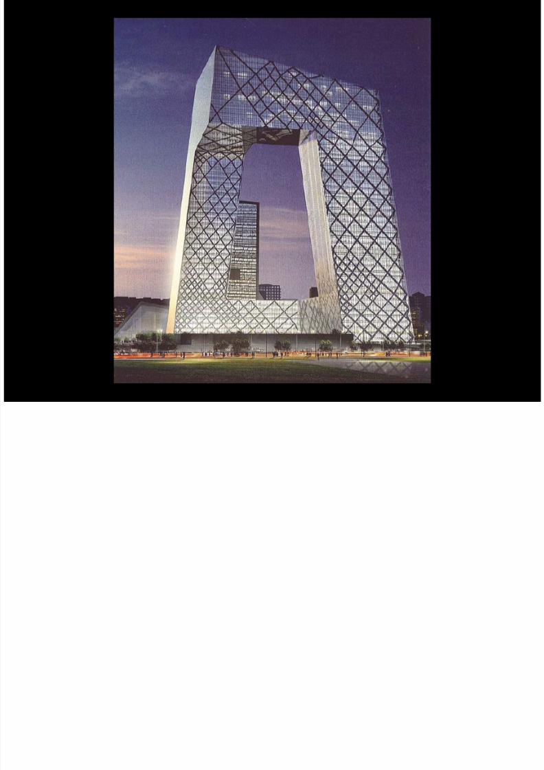
CCTV BUILDING – Beijing, China, 2008 Architect: Ofce for Metropolitan Architecture – Rem Koolhaas | Engineer: Ove Arup – Cecil Balmond
7/30/2019 121101 Kp Ppt Final
http://slidepdf.com/reader/full/121101-kp-ppt-final 5/122
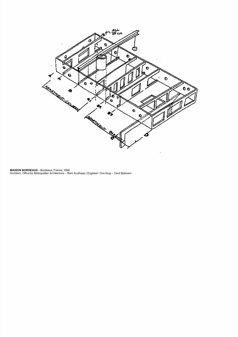
MAISON BORDEAUX – Bordeaux, France, 1998 Architect: Ofce for Metropolitan Architecture – Rem Koolhaas | Engineer: Ove Arup – Cecil Balmond
7/30/2019 121101 Kp Ppt Final
http://slidepdf.com/reader/full/121101-kp-ppt-final 6/122
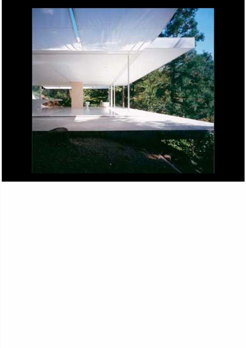
WALL LESS HOUSE – Nagano, Japan, 1997 Architect: Shigeru Ban Architects | Engineer: Hoshino Architect & Engineer
7/30/2019 121101 Kp Ppt Final
http://slidepdf.com/reader/full/121101-kp-ppt-final 7/122NOVARTIS CAMPUS – Basel, Switzerland, 2007
Architect: Kazuyo Sejima + Ryue Nishizawa / SANAA | Engineer: Bollinger + Grohmann and Sasaki and Partners - Sasaki Mutsuro
7/30/2019 121101 Kp Ppt Final
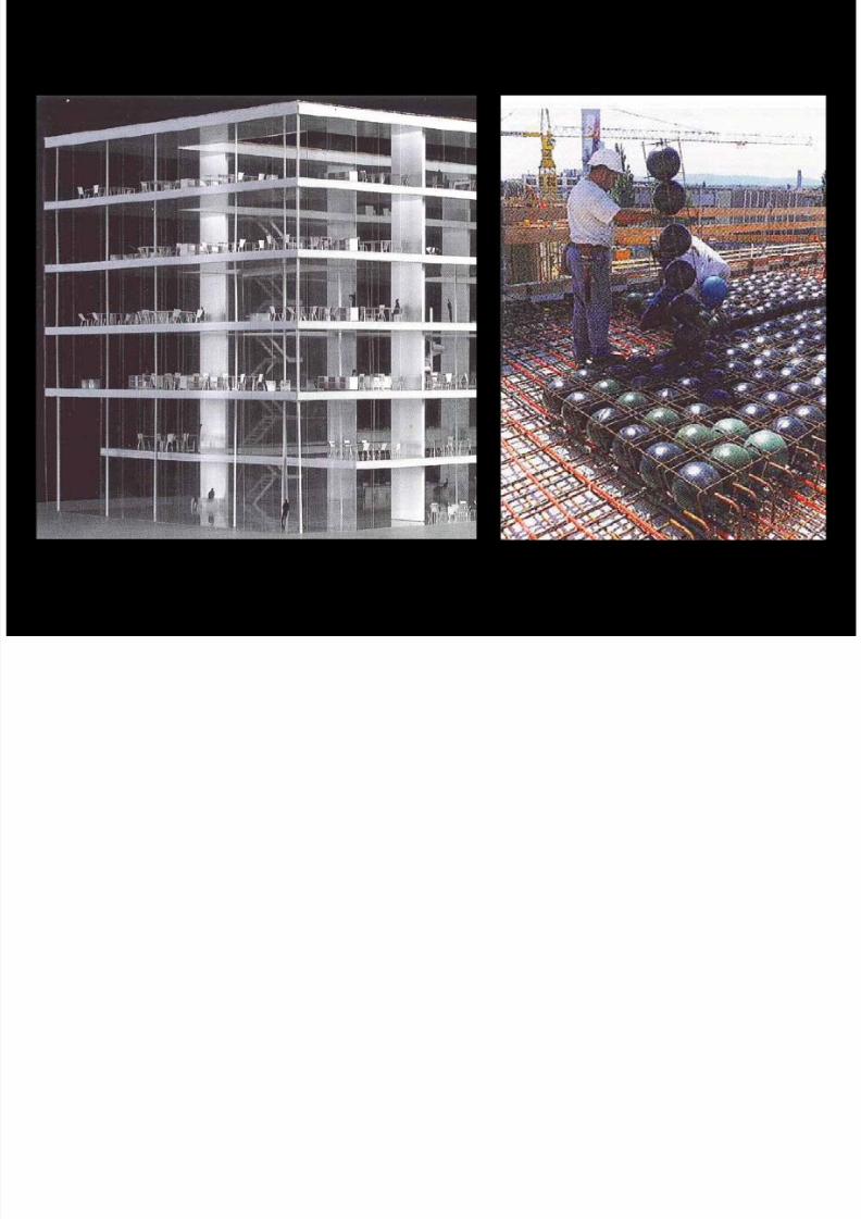
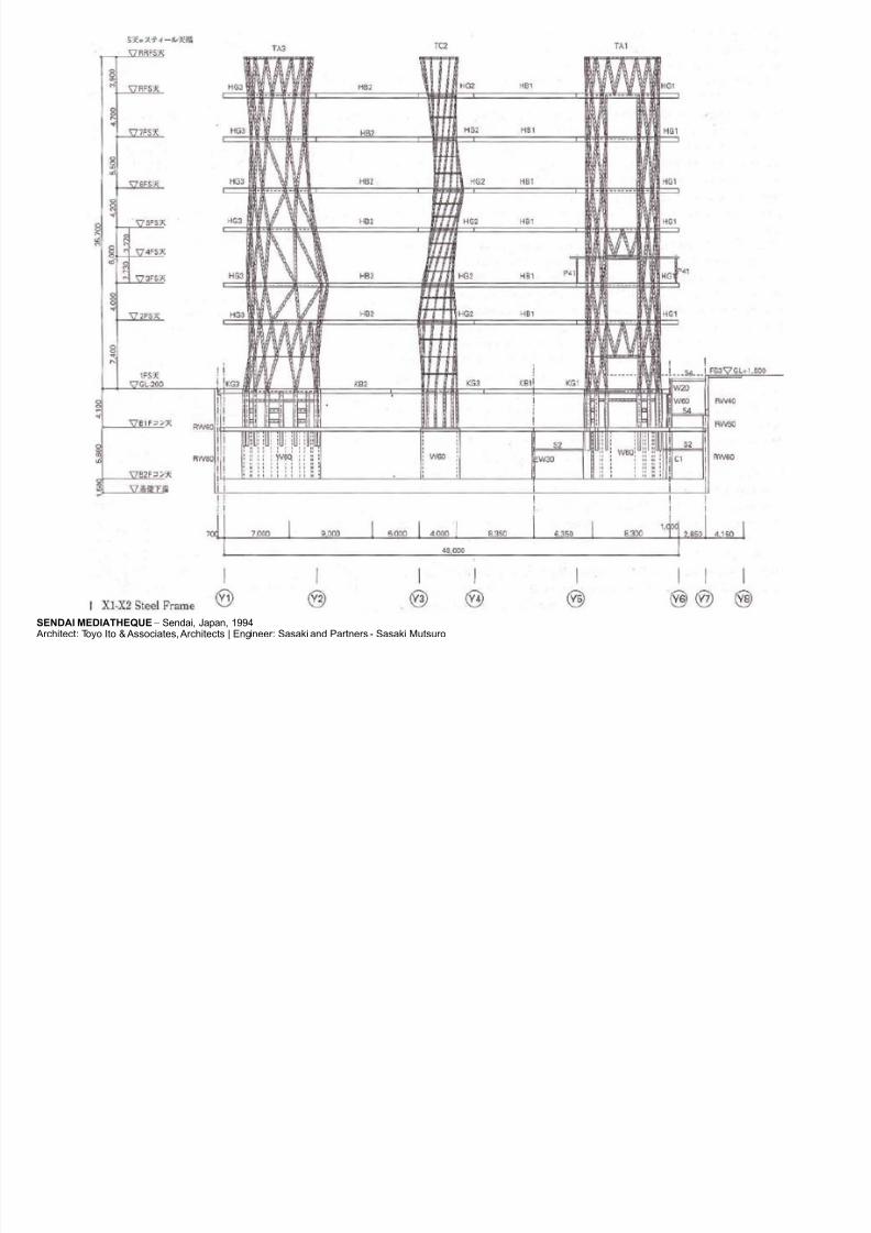
http://slidepdf.com/reader/full/121101-kp-ppt-final 8/122SENDAI MEDIATHEQUE – Sendai, Japan, 1994
Architect: Toyo Ito & Associates, Architects | Engineer: Sasaki and Partners - Sasaki Mutsuro
7/30/2019 121101 Kp Ppt Final
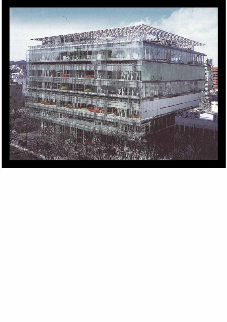
http://slidepdf.com/reader/full/121101-kp-ppt-final 9/122SENDAI MEDIATHEQUE – Sendai, Japan, 1994
Architect: Toyo Ito & Associates, Architects | Engineer: Sasaki and Partners - Sasaki Mutsuro
7/30/2019 121101 Kp Ppt Final
http://slidepdf.com/reader/full/121101-kp-ppt-final 10/122
STRUCTURAL REQUIREMENTS IN SEISMIC ZONE
7/30/2019 121101 Kp Ppt Final
http://slidepdf.com/reader/full/121101-kp-ppt-final 11/122
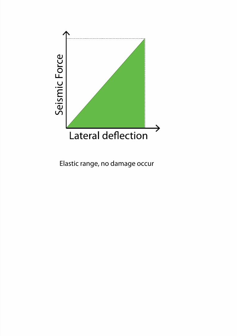
Elastic range, no damage occur
S e i s m i c
F o r c e
7/30/2019 121101 Kp Ppt Final
http://slidepdf.com/reader/full/121101-kp-ppt-final 12/122
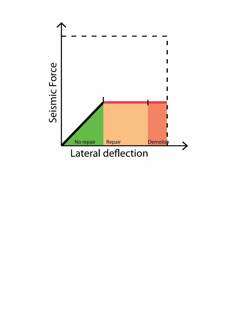
S
e i s m i c F o r c e
No repair Repair Demolish
7/30/2019 121101 Kp Ppt Final
http://slidepdf.com/reader/full/121101-kp-ppt-final 13/122
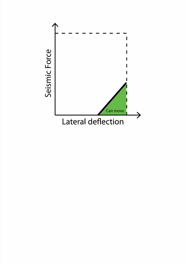
S e i s m i c F o r c e
Can move
7/30/2019 121101 Kp Ppt Final
http://slidepdf.com/reader/full/121101-kp-ppt-final 14/122
CATALOGUE OF EXISTING SEISMIC STRUCTURES
7/30/2019 121101 Kp Ppt Final
http://slidepdf.com/reader/full/121101-kp-ppt-final 15/122
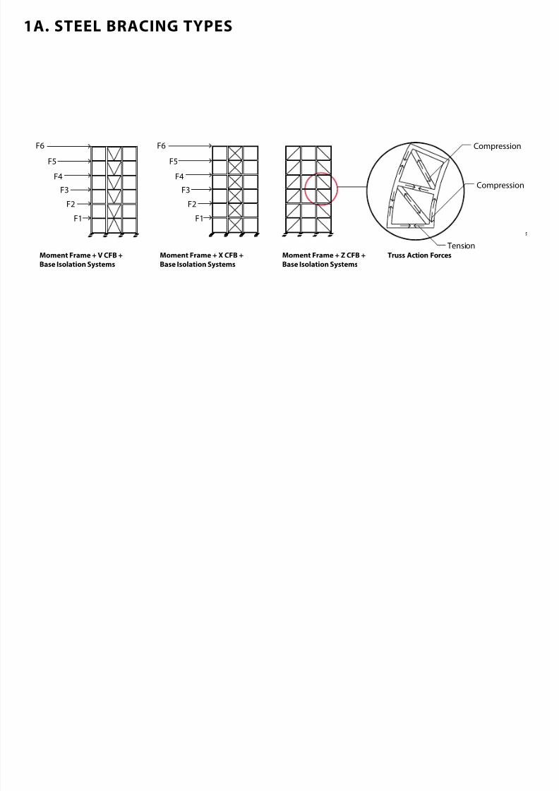
1A. STEEL BRACING TYPES
F1
F2
F3
F4
F5
F6
F1
F2
F3
F4
F5
F6
Compression
Tension
Compression
Moment Frame + V CFB +Base Isolation Systems
Moment Frame + X CFB +Base Isolation Systems
Moment Frame + Z CFB +Base Isolation Systems
Truss Action Forces
7/30/2019 121101 Kp Ppt Final
http://slidepdf.com/reader/full/121101-kp-ppt-final 16/122
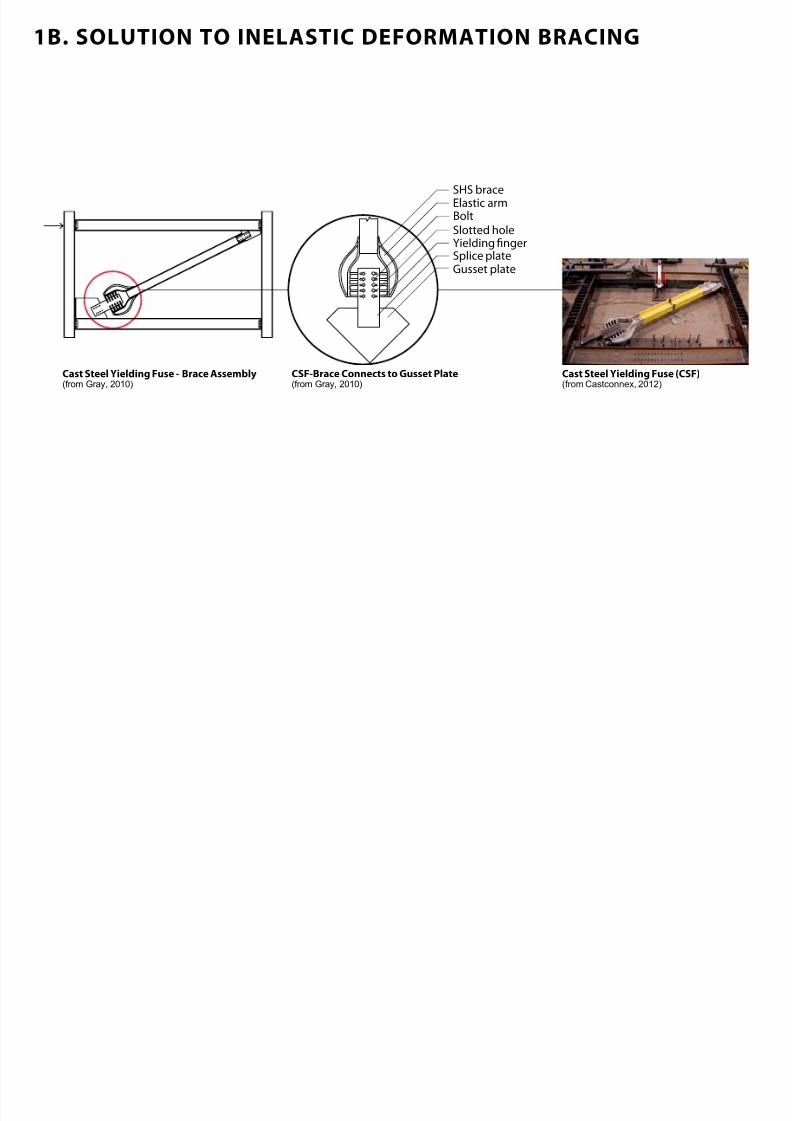
1B. SOLUTION TO INELASTIC DEFORMATION BRACING
SHS brace
BoltElastic arm
Yielding ngerSlotted hole
Splice plateGusset plate
Cast Steel Yielding Fuse Brace Assembly(from Gray, 2010)
CSFBrace Connects to Gusset Plate(from Gray, 2010)
Cast Steel Yielding Fuse CSF(from Castconnex, 2012)
7/30/2019 121101 Kp Ppt Final
http://slidepdf.com/reader/full/121101-kp-ppt-final 17/122
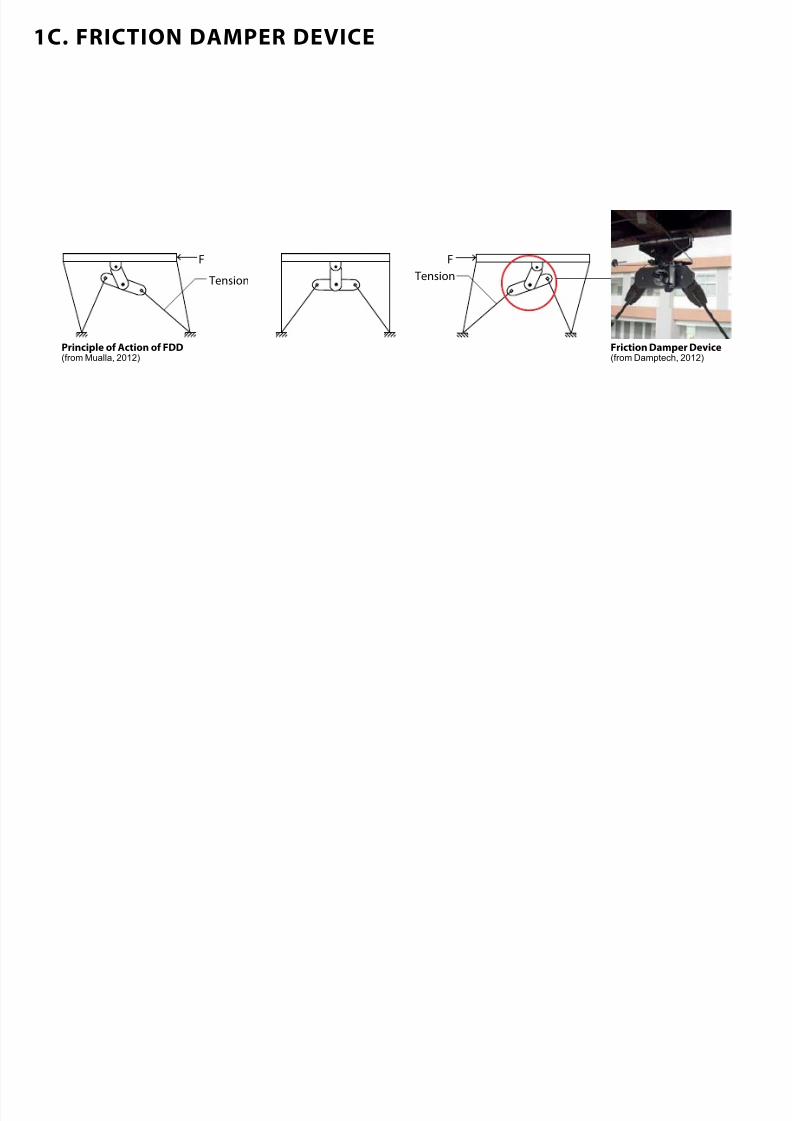
1C. FRICTION DAMPER DEVICE
F F
Tension Tension
Principle o Action o FDD(from Mualla, 2012)
Friction Damper Device(from Damptech, 2012)
7/30/2019 121101 Kp Ppt Final
http://slidepdf.com/reader/full/121101-kp-ppt-final 18/122
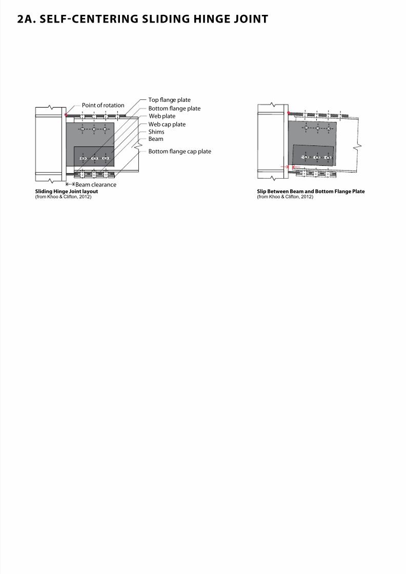
2A. SELF-CENTERING SLIDING HINGE jOINT
Top ange plate
Web plate
Web cap plate
Bottom ange plate
Shims
Bottom ange cap plateBeam
Point of rotation
Beam clearanceSliding Hinge joint layout(from Khoo & Clifton, 2012)
Slip Between Beam and Bottom Flange Plate(from Khoo & Clifton, 2012)
7/30/2019 121101 Kp Ppt Final
http://slidepdf.com/reader/full/121101-kp-ppt-final 19/122
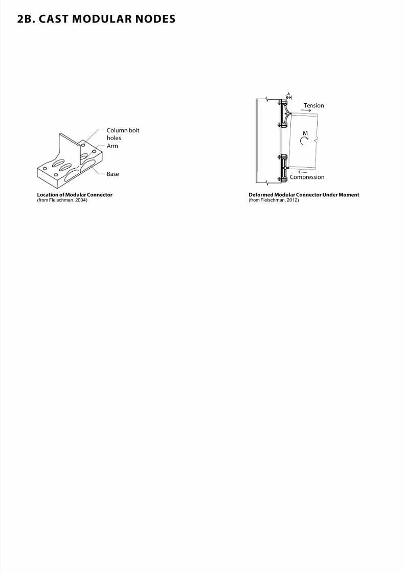
2B. CAST MODULAR NODES
Column bolt
holes
Arm
Base
Tension
Compression
M
Location o Modular Connector(from Fleischman, 2004)
Deormed Modular Connector Under Moment(from Fleischman, 2012)
7/30/2019 121101 Kp Ppt Final
http://slidepdf.com/reader/full/121101-kp-ppt-final 20/122
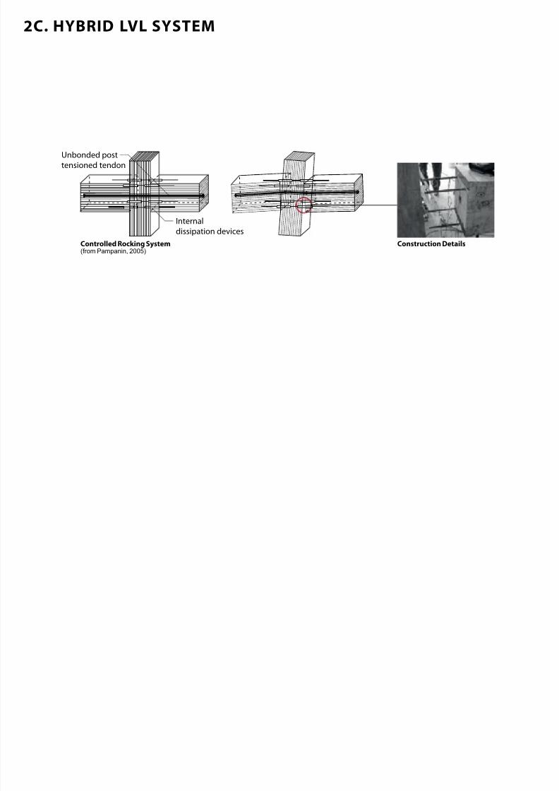
2C. HYBRID LVL SYSTEM
Unbonded post
tensioned tendon
Internal
dissipation devices
Controlled Rocking System(from Pampanin, 2005)
Construction Details
7/30/2019 121101 Kp Ppt Final
http://slidepdf.com/reader/full/121101-kp-ppt-final 21/122
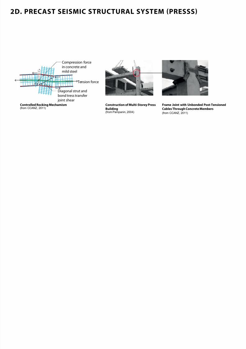
2D. PRECAST SEISMIC STRUCTURAL SYSTEM (PRESSS)
Tension force
Compression force
in concrete and
mild steel
Diagonal strut and
bond tress transfer
joint shear
Controlled Rocking Mechamism(from CCANZ, 2011)
Frame joint with Unbonded PostTensionedCables Through Concrete Members(from CCANZ, 2011)
Construction o MultiStorey PressBuilding(from Pampanin, 2004)
7/30/2019 121101 Kp Ppt Final
http://slidepdf.com/reader/full/121101-kp-ppt-final 22/122
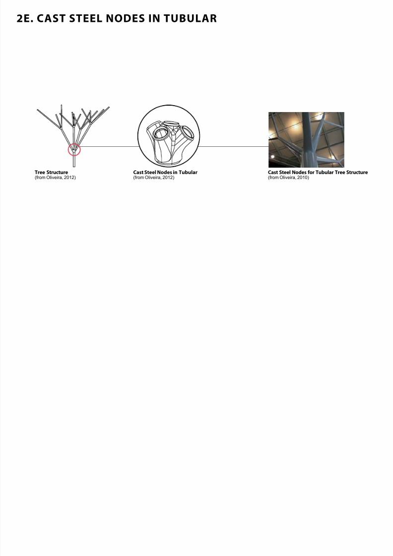
2E. CAST STEEL NODES IN TUBULAR
Cast Steel Nodes in Tubular(from Oliveira, 2012)
Tree Structure(from Oliveira, 2012)
Cast Steel Nodes or Tubular Tree Structure (from Oliveira, 2010)
7/30/2019 121101 Kp Ppt Final
http://slidepdf.com/reader/full/121101-kp-ppt-final 23/122
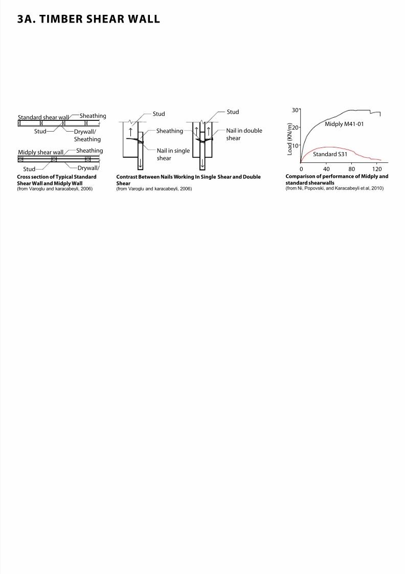
3A. TIMBER SHEAR WALL
SheathingStandard shear wall
Drywall/
Sheathing
Stud
Midply shear wall
Drywall/Stud
Sheathing
Sheathing Nail in double
shear
Nail in single
shear
StudStud
0 40 80 120
10
20
30
Midply M41-01
Standard S31
L o a d ( K N / m )
Comparison o perormance o Midply andstandard shearwalls(from Ni, Popovski, and Karacabeyli et al, 2010)
Cross section o Typical StandardShear Wall and Midply Wall(from Varoglu and karacabeyli, 2006)
Contrast Between Nails Working In Single Shear and DoubleShear(from Varoglu and karacabeyli, 2006)
7/30/2019 121101 Kp Ppt Final
http://slidepdf.com/reader/full/121101-kp-ppt-final 24/122
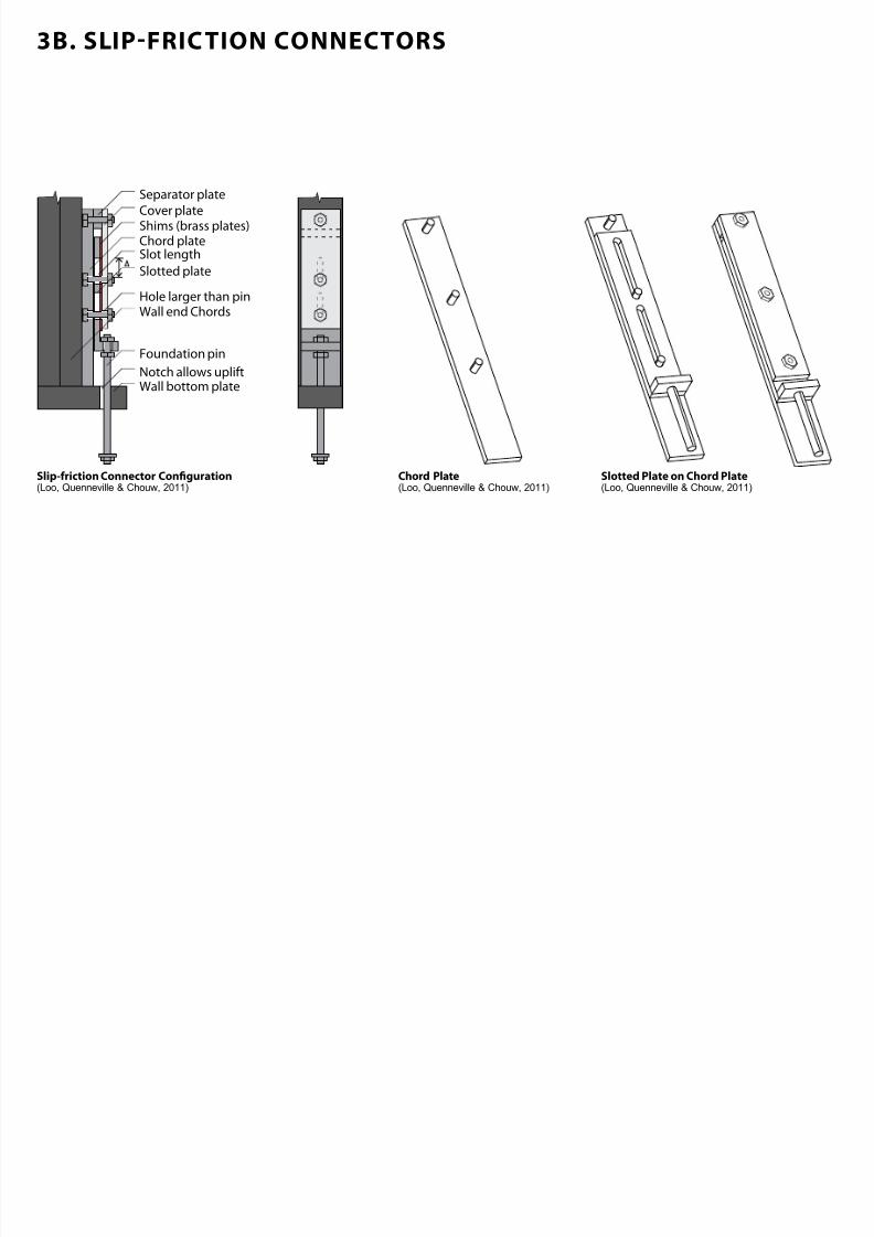
3B. SLIP-FRIC TION CONNECTORS
Foundation pin
Notch allows upliftWall bottom plate
Hole larger than pin
Slot length
Shims (brass plates)Cover plate
Separator plate
Chord plate
Slotted plate
Wall end Chords
Slipriction Connector Conguration(Loo, Quenneville & Chouw, 2011)
Chord Plate(Loo, Quenneville & Chouw, 2011)
Slotted Plate on Chord Plate(Loo, Quenneville & Chouw, 2011)
7/30/2019 121101 Kp Ppt Final
http://slidepdf.com/reader/full/121101-kp-ppt-final 25/122
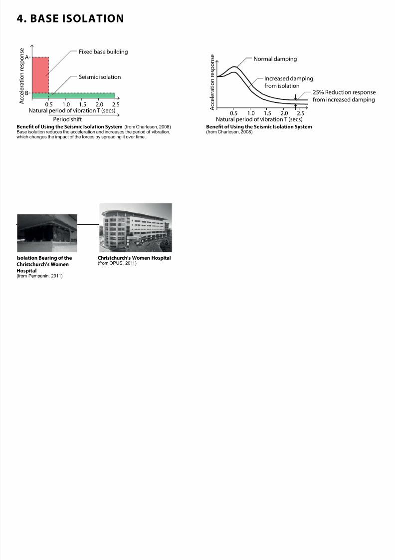
4. BASE ISOLATION
A c c e l e r a t i o n r
e s p o n s e Fixed base building
Seismic isolation
A
B
0.5 1.0 1.5 2.0 2.5Natural period of vibration T (secs)
Period shift
A c c e l e r a t i o n
r e s p o n s e
0.5 1.0 1.5 2.0 2.5Natural period of vibration T (secs)
Increased damping
from isolation
Normal damping
25% Reduction response
from increased damping
Benet o Using the Seismic Isolation System(from Charleson, 2008)
Benet o Using the Seismic Isolation System (from Charleson, 2008)Base isolation reduces the acceleration and increases the period of vibration,
which changes the impact of the forces by spreading it over time.
Isolation Bearing o theChristchurch’s WomenHospital
(from Pampanin, 2011)
Christchurch’s Women Hospital(from OPUS, 2011)
7/30/2019 121101 Kp Ppt Final
http://slidepdf.com/reader/full/121101-kp-ppt-final 26/122
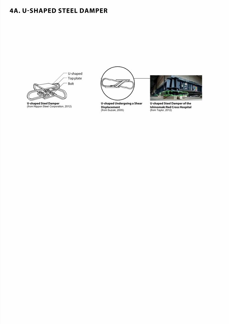
4A. U-SHAPED STEEL DAMPER
U-shaped
Bolt
Top plate
Ushaped Steel Damper(from Nippon Steel Corporation, 2012)
Ushaped Undergoing a ShearDisplacement(from Suzuki, 2005)
Ushaped Steel Damper o theIshinomaki Red Cross Hospital(from Taylor, 2012)
7/30/2019 121101 Kp Ppt Final
http://slidepdf.com/reader/full/121101-kp-ppt-final 27/122
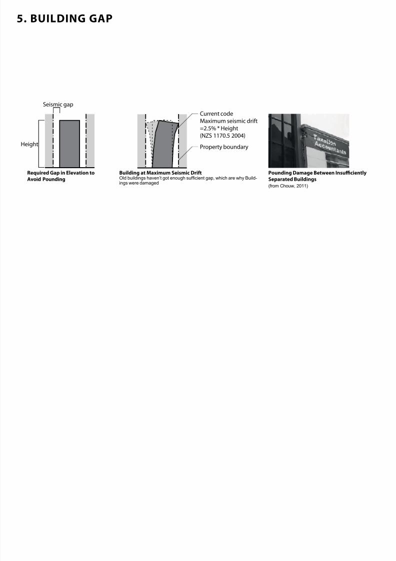
5. BUILDING GAP
Height
Current code
Maximum seismic drift
=2.5% * Height
(NZS 1170.5 2004)
Property boundary
Seismic gap
Required Gap in Elevation toAvoid Pounding
Building at Maximum Seismic DritOld buildings haven’t got enough sufcient gap, which are why Build-ings were damaged
Pounding Damage Between InsucientlySeparated Buildings(from Chouw, 2011)
7/30/2019 121101 Kp Ppt Final
http://slidepdf.com/reader/full/121101-kp-ppt-final 28/122
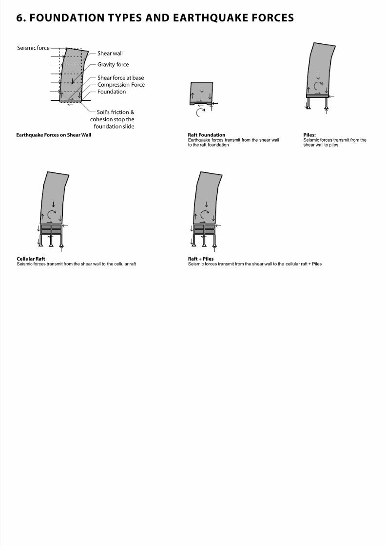
6. FOUNDATION TYPES AND EARTHQUAKE FORCES
Seismic forceShear wall
Gravity force
Compression ForceShear force at base
Foundation
Soil’s friction &
cohesion stop the
foundation slide
Earthquake Forces on Shear Wall Rat FoundationEarthquake forces transmit from the shear wallto the raft foundation
Piles:Seismic forces transmit from theshear wall to piles
Cellular RatSeismic forces transmit from the shear wall to the cellular raft
Rat + PilesSeismic forces transmit from the shear wall to the cellular raft + Piles
7/30/2019 121101 Kp Ppt Final
http://slidepdf.com/reader/full/121101-kp-ppt-final 29/122
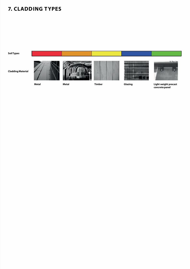
7. CLADDING T YPES
Soil Types
Cladding Material
Metal Metal Timber Glazing Light weight precastconcrete panel

7/30/2019 121101 Kp Ppt Final
http://slidepdf.com/reader/full/121101-kp-ppt-final 30/122
CHRISTCHURCH SOIL CONDITIONS
7/30/2019 121101 Kp Ppt Final
http://slidepdf.com/reader/full/121101-kp-ppt-final 31/122
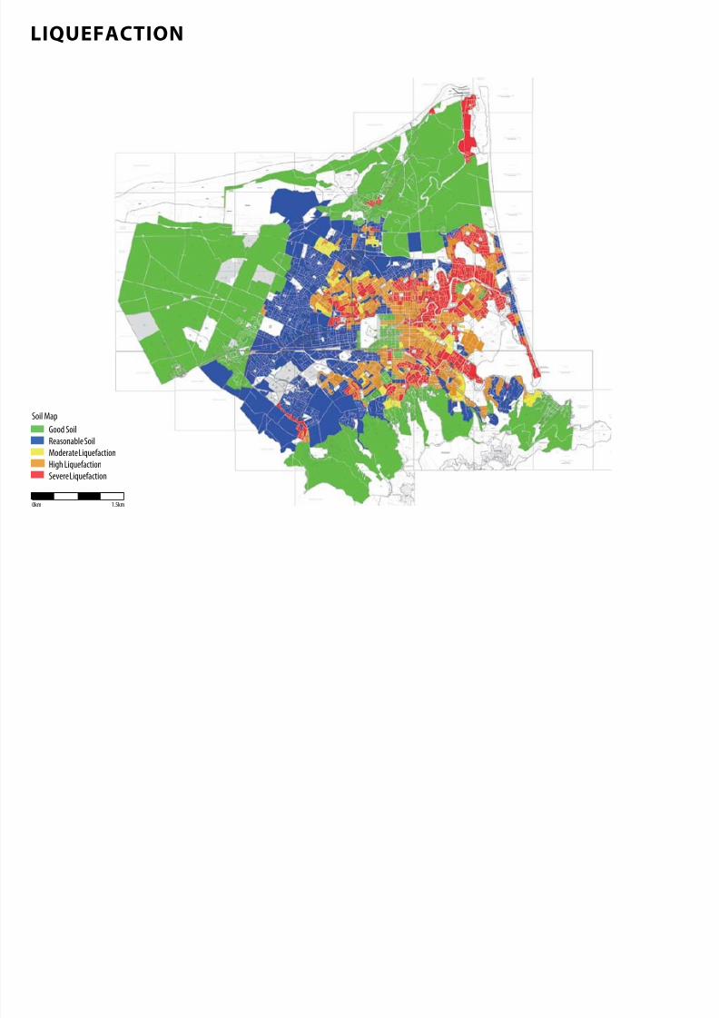
LIQUEFACTION
0km 1.5km
Soil Map
Good Soil
Reasonable Soil
Moderate Liquefaction
High Liquefaction
Severe Liquefaction

7/30/2019 121101 Kp Ppt Final
http://slidepdf.com/reader/full/121101-kp-ppt-final 32/122
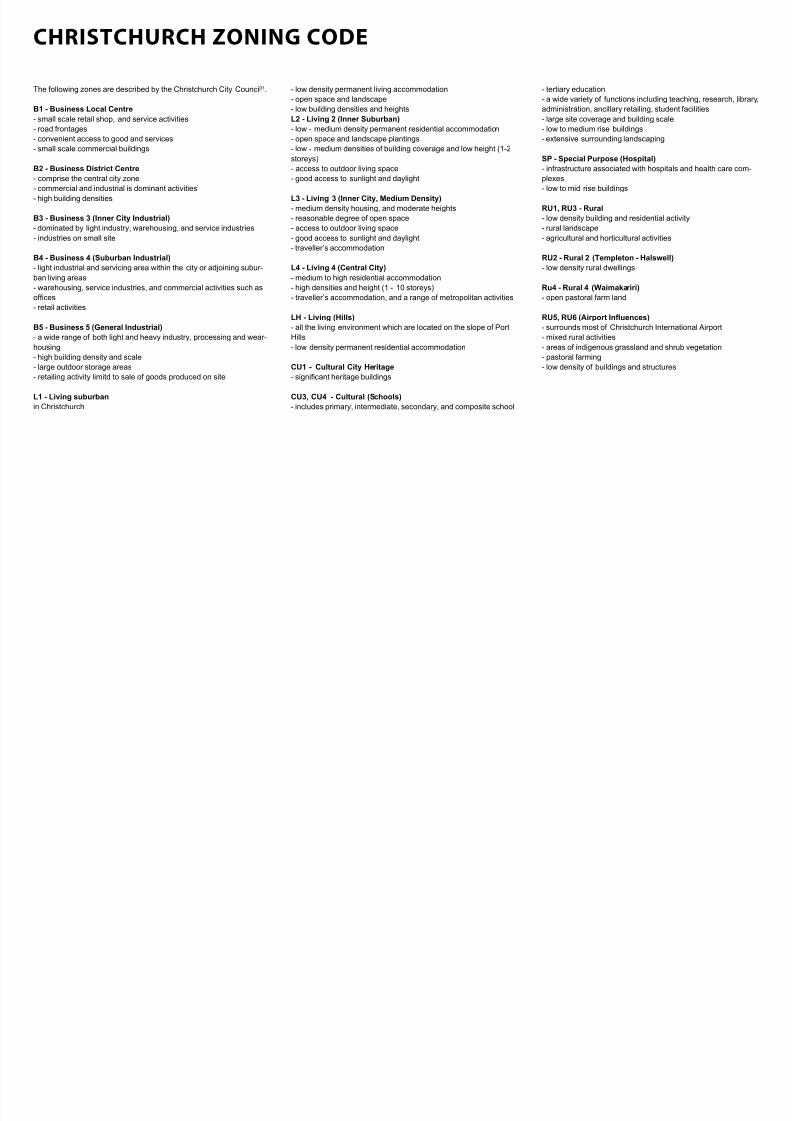
CHRISTCHURCH ZONING CODE
7/30/2019 121101 Kp Ppt Final
http://slidepdf.com/reader/full/121101-kp-ppt-final 33/122
- tertiary education
- a wide variety of functions including teaching, research, library,
administration, ancillary retailing, student facilities
- large site coverage and building scale
- low to medium rise buildings
- extensive surrounding landscaping
SP - Special Purpose (Hospital)
- infrastructure associated with hospitals and health care com-
plexes
- low to mid rise buildings
RU1, RU3 - Rural
- low density building and residential activity
- rural landscape
- agricultural and horticultural activities
RU2 - Rural 2 (Templeton - Halswell)
- low density rural dwellings
Ru4 - Rural 4 (Waimakariri)
- open pastoral farm land
RU5, RU6 (Airport Infuences)
- surrounds most of Christchurch International Airport
- mixed rural activities
- areas of indigenous grassland and shrub vegetation
- pastoral farming
- low density of buildings and structures
The following zones are described by the Christchurch City Council31.
B1 - Business Local Centre
- small scale retail shop, and service activities
- road frontages
- convenient access to good and services- small scale commercial buildings
B2 - Business District Centre
- comprise the central city zone
- commercial and industrial is dominant activities
- high building densities
B3 - Business 3 (Inner City Industrial)
- dominated by light industry, warehousing, and service industries
- industries on small site
B4 - Business 4 (Suburban Industrial)
- light industrial and servicing area within the city or adjoining subur-
ban living areas- warehousing, service industries, and commercial activities such as
ofces
- retail activities
B5 - Business 5 (General Industrial)
- a wide range of both light and heavy industry, processing and wear-
housing
- high building density and scale
- large outdoor storage areas
- retailing activity limitd to sale of goods produced on site
L1 - Living suburban
in Christchurch
- low density permanent living accommodation
- open space and landscape
- low building densities and heights
L2 - Living 2 (Inner Suburban)
- low - medium density permanent residential accommodation
- open space and landscape plantings- low - medium densities of building coverage and low height (1-2
storeys)
- access to outdoor living space
- good access to sunlight and daylight
L3 - Living 3 (Inner City, Medium Density)
- medium density housing, and moderate heights
- reasonable degree of open space
- access to outdoor living space
- good access to sunlight and daylight
- traveller’s accommodation
L4 - Living 4 (Central City)
- medium to high residential accommodation- high densities and height (1 - 10 storeys)
- traveller’s accommodation, and a range of metropolitan activities
LH - Living (Hills)
- all the living environment which are located on the slope of Port
Hills
- low density permanent residential accommodation
CU1 - Cultural City Heritage
- signicant heritage buildings
CU3, CU4 - Cultural (Schools)
- includes primary, intermediate, secondary, and composite school
CHRISTCHURCH ZONING CODE

7/30/2019 121101 Kp Ppt Final
http://slidepdf.com/reader/full/121101-kp-ppt-final 34/122
ZONING CODE : SOIL CONDITIONS :SEISMIC STRUCTURE CATALOGUE
7/30/2019 121101 Kp Ppt Final
http://slidepdf.com/reader/full/121101-kp-ppt-final 35/122
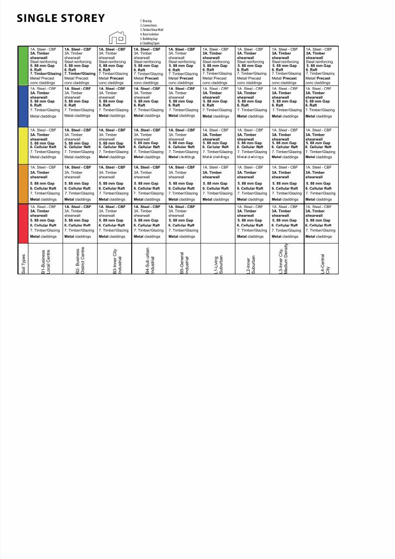
SINGLE STOREY 1. Bracing
2. Connections
3. Timber Shear Wall
4. Base Isolation
5. Building Gap
6. Cladding Types
6. Raft7. Timber/Glazing
Metal/ Precast
conc claddings
Steel reinforcing
6. Raft7. Timber/Glazing
Metal/ Precast
conc claddings
Steel reinforcing
6. Raft7. Timber/Glazing
Metal/ Precast
conc claddings
Steel reinforcing
6. Raft7. Timber/Glazing
Metal/ Precast
conc claddings
Steel reinforcing
6. Raft7. Timber/Glazing
Metal/ Precast
conc claddings
Steel reinforcing
6. Raft7. Timber/Glazing
Metal/ Precast
conc claddings
Steel reinforcing
6. Raft7. Timber/Glazing
Metal/ Precast
conc claddings
Steel reinforcing
6. Raft7. Timber/Glazing
Metal/ Precast
conc claddings
Steel reinforcing
6. Raft7. Timber/Glazing
Metal/ Precast
conc claddings
Steel reinforcing
6. Raft
Metal claddings
6. Raft
Metal claddings
1A. Steel - CBF
6. Raft
1A. Steel - CBF
6. Raft
1A. Steel - CBF
6. Raft
1A. Steel - CBF
6. Raft
Metal claddings
6. Raft
Metal claddings
6. Raft
Metal claddingsMetal claddings Metal claddings Metal claddings
6. Cellular Raft
Metal claddings
6. Cellular Raft 6. Cellular Raft 6. Cellular Raft 6. Cellular Raft 6. Cellular Raft 6. Cellular Raft 6. Cellular Raft 6. Cellular Raft
Metal claddings Metal claddings Metal claddings Metal c laddings Metal claddings Metal claddings Metal claddings Metal claddings
6. Cellular Raft
Metal claddings
6. Cellular Raft
Metal claddings
6. Cellular Raft
Metal claddings
6. Cellular Raft
Metal claddings
6. Cellular Raft
Metal claddings
6. Cellular Raft
Metal claddings
6. Cellular Raft
Metal claddings
6. Cellular Raft
Metal claddings
6. Cellular Raft
Metal claddings
7. Timber/Glazing
6. Cellular Raft 6. Cellular Raft 6. Cellular Raft 6. Cellular Raft 6. Cellular Raft 6. Cellular Raft 6. Cellular Raft 6. Cellular Raft
Metal claddings Metal claddings Metal claddings Metal claddings Metal claddings Metal claddings Metal claddings Metal claddings
7. Timber/Glazing
Metal claddings
1A. Steel - CBF 1A. Steel - CBF 1A. Steel - CBF 1A. Steel - CBF
1A. Steel - CBF 1A. Steel - CBF
1A. Steel - CBF 1A. Steel - CBF 1A. Steel - CBF 1A. Steel - CBF
1A. Steel - CBF 1A. Steel - CBF 1A. Steel - CBF 1A. Steel - CBF
1A. Steel - CBF 1A. Steel - CBF1A. Steel - CBF 1A. Steel - CBF 1A. Steel - CBF
1A. Steel - CBF 1A. Steel - CBF1A. Steel - CBF 1A. Steel - CBF
1A. Steel - CBF 1A. Steel - CBF 1A. Steel - CBF1A. Steel - CBF 1A. Steel - CBF
1A. Steel - CBF 1A. Steel - CBF 1A. Steel - CBF1A. Steel - CBF 1A. Steel - CBF
1A. Steel - CBF 1A. Steel - CBF 1A. Steel - CBF1A. Steel - CBF
1A. Steel - CBF 1A. Steel - CBF
B 1 - B u s
i n e s s
L o c a
l C e n
t r e
B 2 -
B u s
i n e s s
D i s t r i c t C e n
t r e
B 3 - I n n e r
C i t y
I n d u s
t r i a l
B 4 - S u
b u r b a n
I n d u s
t r i a l
B 5 - G e n e r a
l
I n d u s
t r i a l
L 1 - L
i v i n g
S u
b u r b a n
L 2 - I n n e r
S u
b u r b a n
L 3 - I n n e r
C i t y
,
M e
d i u m
D e n s
i t y
L 4 - C e n
t r a l
C i t y
S o
i l T y p e s
3A. Timber
shearwall
3A. Timber
shearwall
3A. Timber
shearwall
3A. Timber
shearwall
3A. Timber shearwall
3A. Timber shearwall
3A. Timber shearwall
3A. Timber shearwall
3A. Timber
shearwall
3A. Timber
shearwall
3A. Timber
shearwall
3A. Timber
shearwall
3A. Timber
shearwall
3A. Timber
shearwall
3A. Timber
shearwall
3A. Timber
shearwall
3A. Timber
shearwall
3A. Timber
shearwall
3A. Timber
shearwall
3A. Timber
shearwall
7. Timber/Glazing 7. Timber/Glazing 7. Timber/Glazing 7. Timber/Glazing 7. Timber/Glazing 7. Timber/Glazing 7. Timber/Glazing7. Timber/Glazing
7. Timber/Glazing 7. Timber/Glazing 7. Timber/Glazing 7. Timber/Glazing 7. Timber/Glazing 7. Timber/Glazing 7. Timber/Glazing 7. Timber/Glazing 7. Timber/Glazing
7. Timber/Glazing 7. Timber/Glazing 7. Timber/Glazing 7. Timber/Glazing 7. Timber/Glazing 7. Timber/Glazing 7. Timber/Glazing 7. Timber/Glazing
7. Timber/Glazing 7. Timber/Glazing 7. Timber/Glazing 7. Timber/Glazing 7. Timber/Glazing 7. Timber/Glazing 7. Timber/Glazing
3A. Timber
shearwall
3A. Timber
shearwall
3A. Timber
shearwall
3A. Timber
shearwall
3A. Timber
shearwall
3A. Timber shearwall
3A. Timber shearwall
3A. Timber shearwall
3A. Timber shearwall
3A. Timber
shearwall
3A. Timber
shearwall
3A. Timber
shearwall
3A. Timber
shearwall
3A. Timber
shearwall
3A. Timber
shearwall
3A. Timber
shearwall
3A. Timber
shearwall
3A. Timber
shearwall
3A. Timber
shearwall
3A. Timber
shearwall
3A. Timber
shearwall
3A. Timber
shearwall
3A. Timber
shearwall
5. 88 mm Gap 5. 88 mm Gap 5. 88 mm Gap 5. 88 mm Gap 5. 88 mm Gap 5. 88 mm Gap 5. 88 mm Gap 5. 88 mm Gap 5. 88 mm Gap
5. 88 mm Gap 5. 88 mm Gap 5. 88 mm Gap 5. 88 mm Gap 5. 88 mm Gap 5. 88 mm Gap 5. 88 mm Gap 5. 88 mm Gap
5. 88 mm Gap 5. 88 mm Gap 5. 88 mm Gap 5. 88 mm Gap 5. 88 mm Gap 5. 88 mm Gap 5. 88 mm Gap 5. 88 mm Gap 5. 88 mm Gap
5. 88 mm Gap 5. 88 mm Gap 5. 88 mm Gap 5. 88 mm Gap 5. 88 mm Gap 5. 88 mm Gap 5. 88 mm Gap 5. 88 mm Gap 5. 88 mm Gap
5. 88 mm Gap 5. 88 mm Gap 5. 88 mm Gap 5. 88 mm Gap 5. 88 mm Gap 5. 88 mm Gap 5. 88 mm Gap 5. 88 mm Gap
6. Raft
1A. Steel - CBF
7. Timber/Glazing
3A. Timber shearwall5. 88 mm Gap
7/30/2019 121101 Kp Ppt Final
http://slidepdf.com/reader/full/121101-kp-ppt-final 36/122
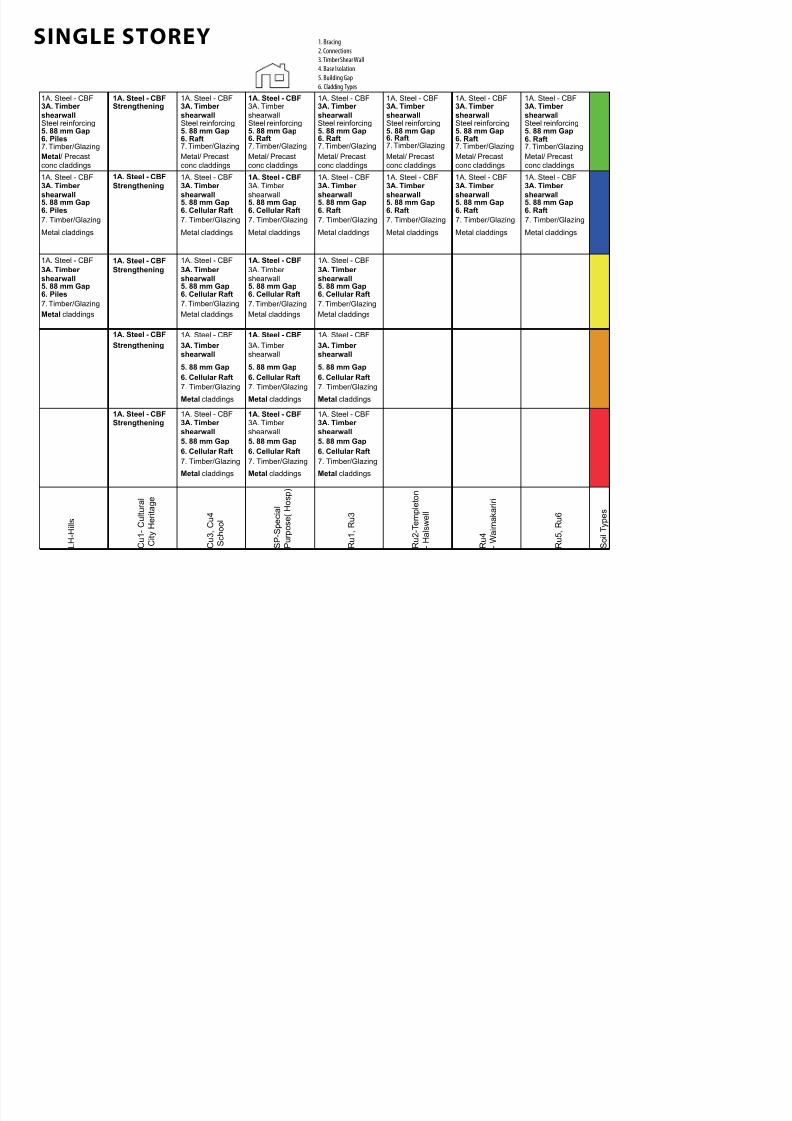
SINGLE STOREY 1. Bracing
2. Connections
3. Timber Shear Wall
4. Base Isolation
5. Building Gap
6. Cladding Types
6. Piles7. Timber/Glazing
Metal/ Precastconc claddings
5. 88 mm GapSteel reinforcing
1A. Steel - CBF 1A. Steel - CBFStrengthening
6. Raft7. Timber/Glazing
Metal/ Precastconc claddings
5. 88 mm Gap
1A. Steel - CBF
Steel reinforcing
6. Raft7. Timber/Glazing
Metal/ Precastconc claddings
5. 88 mm Gap
1A. Steel - CBF
Steel reinforcing
6. Raft7. Timber/Glazing
Metal/ Precastconc claddings
5. 88 mm Gap
1A. Steel - CBF
Steel reinforcing
6. Raft7. Timber/Glazing
Metal/ Precastconc claddings
5. 88 mm Gap
1A. Steel - CBF
Steel reinforcing
6. Raft7. Timber/Glazing
Metal/ Precastconc claddings
5. 88 mm Gap
1A. Steel - CBF
Steel reinforcing
6. Raft7. Timber/Glazing
Metal/ Precastconc claddings
5. 88 mm Gap
1A. Steel - CBF
Steel reinforcing
6. Piles
Metal claddings
5. 88 mm Gap
1A. Steel - CBF 1A. Steel - CBF
6. Cellular Raft
Metal claddings
5. 88 mm Gap
1A. Steel - CBF
6. Cellular Raft
Metal claddings
5. 88 mm Gap
1A. Steel - CBF
6. Raft
Metal claddings
5. 88 mm Gap
1A. Steel - CBF
6. Raft
Metal claddings
5. 88 mm Gap
1A. Steel - CBF
6. Raft
Metal claddings
5. 88 mm Gap
1A. Steel - CBF
6. Raft
Metal claddings
5. 88 mm Gap
1A. Steel - CBFStrengthening
7. Timber/Glazing 7. Timber/Glazing 7. Timber/Glazing7. Timber/Glazing 7. Timber/Glazing 7. Timber/Glazing 7. Timber/Glazing
6. Piles5. 88 mm Gap
1A. Steel - CBF 1A. Steel - CBF
Strengthening
6. Cellular Raft5. 88 mm Gap
1A. Steel - CBF
6. Cellular Raft5. 88 mm Gap
1A. Steel - CBF
6. Cellular Raft5. 88 mm Gap
1A. Steel - CBF
Metal claddings
7. Timber/Glazing
Metal claddings
7. Timber/Glazing
Metal claddings
7. Timber/Glazing
Metal claddings
7. Timber/Glazing
1A. Steel - CBF
Strengthening
6. Cellular Raft
Metal claddings
5. 88 mm Gap
1A. Steel - CBF
6. Cellular Raft
Metal claddings
5. 88 mm Gap
1A. Steel - CBF
6. Cellular Raft
Metal claddings
5. 88 mm Gap
1A. Steel - CBF
7. Timber/Glazing 7. Timber/Glazing 7. Timber/Glazing
1A. Steel - CBFStrengthening
6. Cellular Raft
5. 88 mm Gap
1A. Steel - CBF
6. Cellular Raft
5. 88 mm Gap
1A. Steel - CBF
6. Cellular Raft
5. 88 mm Gap
1A. Steel - CBF
Metal claddings Metal claddings Metal claddings
7. Timber/Glazing 7. Timber/Glazing 7. Timber/Glazing
3A. Timber
shearwall
3A. Timber
shearwall
3A. Timber
shearwall
3A. Timber
shearwall
3A. Timber
shearwall
3A. Timber
shearwall
3A. Timber
shearwall
3A. Timber
shearwall
3A. Timber
shearwall
3A. Timber
shearwall
3A. Timber
shearwall
3A. Timber
shearwall
3A. Timber
shearwall
3A. Timber
shearwall
3A. Timber
shearwall
3A. Timber
shearwall
3A. Timber
shearwall
3A. Timber
shearwall
3A. Timber shearwall
3A. Timber shearwall
3A. Timber shearwall
3A. Timber
shearwall
3A. Timber
shearwall
3A. Timber
shearwall
L H - H i l l s
C u 1 - C u l t u r a l
C i t y H e r i t a g e
C u 3 ,
C u 4
S c h o o l
S P - S p e c i a l
P u r p o s e ( H o s p )
R u 1 ,
R u 3
R u 2 - T e m p l e t o n
- H a l s w e l l
R u 4
- W a i m a k a r i r i
R u 5 ,
R u 6
S o i l T y p e s
7/30/2019 121101 Kp Ppt Final
http://slidepdf.com/reader/full/121101-kp-ppt-final 37/122
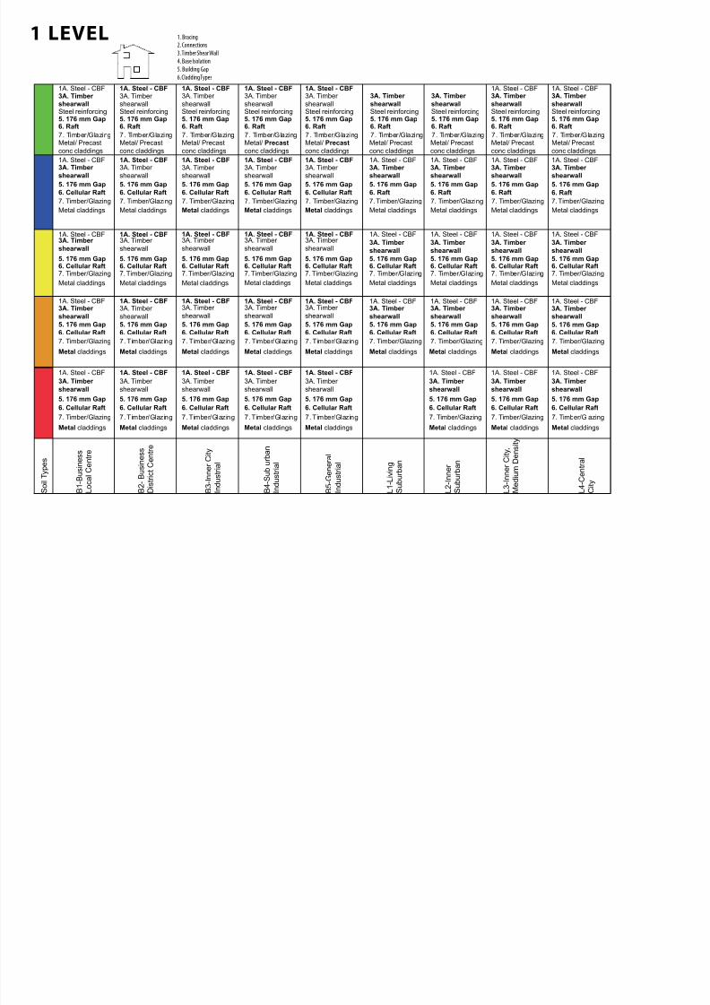
1 LEVEL 1. Bracing
2. Connections
3. Timber Shear Wall
4. Base Isolation
5. Building Gap
6. Cladding Types
6. Raft
3A. Timber
shearwall
Metal/ Precast
conc claddings
5. 176 mm Gap
1A. Steel - CBF
Steel reinforcing
6. Raft
3A. Timber shearwall
Metal/ Precast
conc claddings
5. 176 mm Gap
1A. Steel - CBF
Steel reinforcing
6. Raft
Metal/ Precast
conc claddings
5. 176 mm Gap
1A. Steel - CBF
Steel reinforcing
6. Raft
Metal/ Precast
conc claddings
5. 176 mm Gap
1A. Steel - CBF
Steel reinforcing
6. Raft
Metal/ Precast
conc claddings
5. 176 mm Gap
1A. Steel - CBF
Steel reinforcing
6. Raft
3A. Timber
shearwall
Metal/ Precast
conc claddings
5. 176 mm GapSteel reinforcing
6. Raft
3A. Timber
shearwall
Metal/ Precast
conc claddings
5. 176 mm GapSteel reinforcing
6. Raft
3A. Timber
shearwall
Metal/ Precast
conc claddings
5. 176 mm GapSteel reinforcing
1A. Steel - CBF
6. Raft
3A. Timber
shearwall
Metal/ Precast
conc claddings
5. 176 mm GapSteel reinforcing
1A. Steel - CBF3A. Timber
shearwall
3A. Timber
shearwall
3A. Timber
shearwall
6. Cellular Raft
3A. Timber
shearwall
5. 176 mm Gap
1A. Steel - CBF
Metal claddings
3A. Timber
shearwall
5. 176 mm Gap
1A. Steel - CBF
6. Cellular Raft
5. 176 mm Gap
1A. Steel - CBF
6. Cellular Raft
5. 176 mm Gap
1A. Steel - CBF
6. Cellular Raft
5. 176 mm Gap
1A. Steel - CBF
6. Raft
3A. Timber
shearwall
5. 176 mm Gap
6. Raft
3A. Timber
shearwall
5. 176 mm Gap
6. Raft
3A. Timber
shearwall
5. 176 mm Gap
1A. Steel - CBF
6. Cellular Raft
Metal claddings Metal claddings Metal claddings Metal claddings Metal claddings Metal claddings
3A. Timber shearwall
3A. Timber shearwall
3A. Timber shearwall
1A. Steel - CBF 1A. Steel - CBF
Metal claddings
Metal claddings
6. Cellular Raft
3A. Timber
shearwall5. 176 mm Gap
1A. Steel - CBF
Metal claddings
6. Cellular Raft
3A. Timber
shearwall5. 176 mm Gap
1A. Steel - CBF
Metal claddings
6. Cellular Raft5. 176 mm Gap
1A. Steel - CBF
Metal claddings
6. Cellular Raft5. 176 mm Gap
1A. Steel - CBF
Metal claddings
6. Cellular Raft5. 176 mm Gap
1A. Steel - CBF
Metal claddings
6. Cellular Raft
3A. Timber
shearwall5. 176 mm Gap
Metal claddings
6. Cellular Raft
3A. Timber
shearwall5. 176 mm Gap
Metal claddings
6. Cellular Raft
3A. Timber
shearwall5. 176 mm Gap
1A. Steel - CBF
6. Cellular Raft
3A. Timber
shearwall5. 176 mm Gap
1A. Steel - CBF
Metal claddings
1A. Steel - CBF 1A. Steel - CBF3A. Timber
shearwall
3A. Timber
shearwall
3A. Timber
shearwall
6. Cellular Raft
3A. Timber
shearwall
Metal claddings
5. 176 mm Gap
1A. Steel - CBF
6. Cellular Raft
3A. Timber
shearwall
Metal claddings
5. 176 mm Gap
1A. Steel - CBF
6. Cellular Raft
Metal claddings
5. 176 mm Gap
1A. Steel - CBF
6. Cellular Raft
Metal claddings
5. 176 mm Gap
1A. Steel - CBF
6. Cellular Raft
Metal claddings
5. 176 mm Gap
1A. Steel - CBF
6. Cellular Raft
3A. Timber
shearwall
Metal claddings
5. 176 mm Gap
6. Cellular Raft
3A. Timber
shearwall
Metal claddings
5. 176 mm Gap
6. Cellular Raft
3A. Timber
shearwall
Metal claddings
5. 176 mm Gap
1A. Steel - CBF
6. Cellular Raft
3A. Timber
shearwall
Metal claddings
5. 176 mm Gap
1A. Steel - CBF1A. Steel - CBF 1A. Steel - CBF3A. Timber
shearwall
3A. Timber
shearwall
3A. Timber
shearwall
Metal claddings
6. Cellular Raft
3A. Timber
shearwall
5. 176 mm Gap
1A. Steel - CBF
Metal claddings
6. Cellular Raft
3A. Timber
shearwall
5. 176 mm Gap
1A. Steel - CBF
Metal claddings
6. Cellular Raft
5. 176 mm Gap
1A. Steel - CBF
Metal claddings
6. Cellular Raft
5. 176 mm Gap
1A. Steel - CBF
Metal claddings
6. Cellular Raft
5. 176 mm Gap
1A. Steel - CBF
Metal claddings
6. Cellular Raft
3A. Timber
shearwall
5. 176 mm Gap
Metal claddings
6. Cellular Raft
3A. Timber
shearwall
5. 176 mm Gap
1A. Steel - CBF
Metal claddings
6. Cellular Raft
3A. Timber
shearwall
5. 176 mm Gap
1A. Steel - CBF1A. Steel - CBF3A. Timber
shearwall
3A. Timber
shearwall
3A. Timber
shearwall
7. Timber/Glazing 7. Timber/Glazing 7. Timber/Glazing 7. Timber/Glazing 7. Timber/Glazing 7. Timber/Glazing 7. Timber/Glazing 7. Timber/Glazing 7. Timber/Glazing
7. Timber/Glazing 7. Timber/Glazing 7. Timber/Glazing 7. Timber/Glazing 7. Timber/Glazing 7. Timber/Glazing 7. Timber/Glazing7. Timber/Glazing
7. Timber/Glazing 7. Timber/Glazing 7. Timber/Glazing7. Timber/Glazing7. Timber/Glazing7. Timber/Glazing7. Timber/Glazing7. Timber/Glazing 7. Timber/Glazing
7. Timber/Glazing 7. Timber/Glazing 7. Timber/Glazing 7. Timber/Glazing 7. Timber/Glazing7. Timber/Glazing 7. Timber/Glazing 7. Timber/Glazing 7. Timber/Glazing
7. Timber/Glazing 7. Timber/Glazing 7. Timber/Glazing 7. Timber/Glazing7. Timber/Glazing 7. Timber/Glazing 7. Timber/Glazing 7. Timber/Glazing
6. Raft
3A. Timber
shearwall
5. 176 mm Gap
1A. Steel - CBF
Metal claddings
7. Timber/Glazing
B 1 - B u s
i n e s s
L o c a
l C e n
t r e
B 2 -
B u s
i n e s s
D i s t r i c t C e n
t r e
B 3 - I n n e r
C i t y
I n d u s
t r i a l
B 4 - S u
b u r b a n
I n d u s
t r i a l
B 5 - G e n e r a
l
I n d u s
t r i a l
L 1 - L
i v i n g
S u
b u r b a n
L 2 - I n n e r
S u
b u r b a n
L 3 - I n n e r
C i t y
,
M e
d i u m
D e n s
i t y
L 4 - C e n
t r a l
C i t y
S o
i l T y p e s

7/30/2019 121101 Kp Ppt Final
http://slidepdf.com/reader/full/121101-kp-ppt-final 38/122
1 LEVEL 1. Bracing
2. Connections
3. Timber Shear Wall
4. Base Isolation
5. Building Gap
6. Cladding Types
6. Piles
3A. Timber shearwall
Metal/ Precast
conc claddings
5. 176 mm GapSteel reinforcing
1A. Steel - CBF 1A. Steel - CBFStrengthening
6. Raft
3A. Timber shearwall
Metal/ Precast
conc claddings
5. 176 mm Gap
1A. Steel - CBF
Steel reinforcing
6. Raft
Metal/ Precast
conc claddings
5. 176 mm Gap
1A. Steel - CBF
Steel reinforcing
3A. Timber shearwall
6. Raft
3A. Timber shearwall
Metal/ Precast
conc claddings
5. 176 mm Gap
1A. Steel - CBF
Steel reinforcing
6. Raft
3A. Timber shearwall
Metal/ Precast
conc claddings
5. 176 mm Gap
1A. Steel - CBF
Steel reinforcing
6. Raft
3A. Timber
shearwall
Metal/ Precast
conc claddings
5. 176 mm Gap
1A. Steel - CBF
Steel reinforcing
6. Raft
3A. Timber
shearwall
Metal/ Precast
conc claddings
5. 176 mm Gap
1A. Steel - CBF
Steel reinforcing
6. Piles
3A. Timber shearwall
5. 176 mm Gap
1A. Steel - CBF 1A. Steel - CBF
6. Cellular Raft
3A. Timber shearwall
5. 176 mm Gap
1A. Steel - CBF
6. Cellular Raft
3A. Timber shearwall
5. 176 mm Gap
1A. Steel - CBF
6. Raft
3A. Timber shearwall
5. 176 mm Gap
1A. Steel - CBF
6. Raft
3A. Timber
shearwall
5. 176 mm Gap
1A. Steel - CBF
6. Raft
3A. Timber
shearwall
5. 176 mm Gap
1A. Steel - CBF
6. Raft
3A. Timber
shearwall
5. 176 mm Gap
1A. Steel - CBF
Metal claddings Metal claddings Metal claddings
Strengthening
Metal claddings Metal claddings Metal claddings Metal claddings
Metal claddings
6. Piles
3A. Timber
shearwall5. 176 mm Gap
1A. Steel - CBF 1A. Steel - CBFStrengthening
Metal claddings
6. Cellular Raft
3A. Timber
shearwall5. 176 mm Gap
1A. Steel - CBF
Metal claddings
6. Cellular Raft
3A. Timber
shearwall5. 176 mm Gap
1A. Steel - CBF
Metal claddings
6. Cellular Raft
3A. Timber
shearwall5. 176 mm Gap
1A. Steel - CBF
1A. Steel - CBFStrengthening
6. Cellular Raft
3A. Timber
shearwall
Metal claddings
5. 176 mm Gap
1A. Steel - CBF
6. Cellular Raft
3A. Timber
shearwall
Metal claddings
5. 176 mm Gap
1A. Steel - CBF
6. Cellular Raft
3A. Timber
shearwall
Metal claddings
5. 176 mm Gap
1A. Steel - CBF
1A. Steel - CBFStrengthening
Metal claddings
6. Cellular Raft
3A. Timber
shearwall
5. 176 mm Gap
1A. Steel - CBF
Metal claddings
6. Cellular Raft
3A. Timber
shearwall
5. 176 mm Gap
1A. Steel - CBF
Metal claddings
6. Cellular Raft
3A. Timber
shearwall
5. 176 mm Gap
1A. Steel - CBF
7. Timber/Glazing 7. Timber/Glazing 7. Timber/Glazing 7. Timber/Glazing 7. Timber/Glazing 7. Timber/Glazing 7. Timber/Glazing
7. Timber/Glazing 7. Timber/Glazing 7. Timber/Glazing7. Timber/Glazing 7. Timber/Glazing 7. Timber/Glazing 7. Timber/Glazing
7. Timber/Glazing 7. Timber/Glazing 7. Timber/Glazing 7. Timber/Glazing
7. Timber/Glazing 7. Timber/Glazing 7. Timber/Glazing
7. Timber/Glazing 7. Timber/Glazing 7. Timber/Glazing
L H - H i l l s
C u 1 - C u l t u r a l
C i t y H e r i t a g e
C u 3 ,
C u 4
S c h o o l
S P - S p e c i a l
P u r p o s e ( H o s p )
R u 1 ,
R u 3
R u 2 - T e m p l e t o n
- H a l s w e l l
R u 4
- W a i m a k a r i r i
R u 5 ,
R u 6
S o i l T y p e s
7/30/2019 121101 Kp Ppt Final
http://slidepdf.com/reader/full/121101-kp-ppt-final 39/122
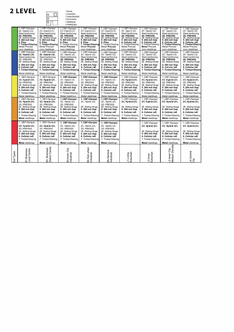
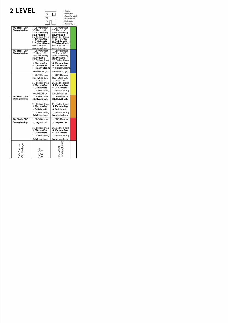
2 LEVEL 1. Bracing
2. Connections
3. Timber Shear Wall
4. Base Isolation
5. Building Gap
6. Cladding Types
6. Cellular raft5. 264 mm Gap
6. Cellular raft
5. 264 mm Gap
6. Cellular raft5. 264 mm Gap
6. Cellular raft5. 264 mm Gap
6. Cellular raft5. 264 mm Gap
6. Cellular raft
5. 264 mm Gap
6. Cellular raft
5. 264 mm Gap
6. Cellular raft
5. 264 mm Gap
2C. Hybrid LVL 2C. Hybrid LVL 2C. Hybrid LVL 2C. Hybrid LVL 2C. Hybrid LVL
2D. PRESSS 2D. PRESSS 2D. PRESSS 2D. PRESSS2D. PRESSS
1. CBF+Damper 1. CBF+Damper 1. CBF+Damper
1. CBF+Damper 1. CBF+Damper 2C. Hybr id LVL 2C. Hybr id LVL 2C. Hybrid LVL
1. CBF+Damper 1. CBF+Damper 1. CBF+Damper
Metal claddings Metal claddings
7. Timber/Glazing
Metal claddings Metal claddings Metal claddings Metal claddings
7. Timber/Glazing
Metal claddings
7. Timber/Glazing
Metal claddings
7. Timber/Glazing7. Timber/Glazing 7. Timber/Glazing 7. Timber/Glazing 7. Timber/Glazing
B 1 - B u s
i n e s s
L o c a
l C e n
t r e
B 2 -
B u s
i n e s s
D i s t r i c t C e n
t r e
B 3 - I n n e r
C i t y
I n d u s
t r i a l
B 4 - S u
b u r b a n
I n d u s
t r i a l
B 5 - G e n e r a
l
I n d u s
t r i a l
L 1 - L
i v i n g
S u
b u r b a n
L 2 - I n n e r
S u
b u r b a n
L 3 - I n n e r
C i t y
,
M e
d i u m
D e n s
i t y
L 4 - C e n
t r a l
C i t y
S o
i l T y p e s
6. Piles
2C. Hybrid LVL
7. Timber/GlazingMetal/ Precast
conc claddings
5. 264 mm Gap
Steel reinforcing
6. Piles7. Timber/GlazingMetal/ Precastconc claddings
5. 264 mm Gap
Steel reinforcing
6. Piles7. Timber/GlazingMetal/ Precast conc claddings
5. 264 mm Gap
1. CBF+Damper
Steel reinforcing
6. Piles7. Timber/GlazingMetal/ Precast conc claddings
5. 264 mm Gap
Steel reinforcing
6. Piles7. Timber/GlazingMetal/ Precastconc claddings
5. 264 mm Gap
Steel reinforcing
7. Timber/GlazingMetal/ Precastconc claddings
5. 264 mm Gap
Steel reinforcing
7. Timber/GlazingMetal/ Precastconc claddings
5. 264 mm Gap
Steel reinforcing
7. Timber/GlazingMetal/ Precastconc claddings
5. 264 mm Gap
Steel reinforcing
7. Timber/GlazingMetal/ Precastconc claddings
5. 264 mm Gap
Steel reinforcing2C. Hybrid LVL 2C. Hybrid LVL 2C. Hybrid LVL 2C. Hybrid LVL
2D. PRESSS 2D. PRESSS 2D. PRESSS 2D. PRESSS 2D. PRESSS
1. CBF+Damper 1. CBF+Damper 1. CBF+Damper 1. CBF+Damper
6. Cellular raft 6. Cellular raft 6. Cellular raft6. Cellular raft
2C. Hybrid LVL 2C. Hybrid LVL 2C. Hybrid LVL 2C. Hybrid LVL1. CBF+Damper
2D. PRESSS 2D. PRESSS 2D. PRESSS 2D. PRESSS
1. CBF+Damper 1. CBF+Damper 1. CBF+Damper
6. Cellular raft7. Timber/Glazing
Metal claddings
7. Timber/Glazing
Metal claddings
6. Cellular raft 6. Cellular raft 6. Cel lular raft7. Timber/Glazing
Metal claddings
7. Timber/Glazing
Metal claddings
7. Timber/Glazing
Metal claddings
6. Cellular raft7. Timber/Glazing
Metal claddings
7. Timber/Glazing
Metal claddings
7. Timber/Glazing
Metal claddings
2C. Hybrid LVL
5. 264 mm Gap
Steel reinforcing
5. 264 mm Gap
Steel reinforcing
5. 264 mm Gap
1. CBF+Damper
Steel reinforcing
5. 264 mm Gap
Steel reinforcing
5. 264 mm Gap
Steel reinforcing
5. 264 mm Gap
Steel reinforcing
5. 264 mm Gap
Steel reinforcing
5. 264 mm Gap
Steel reinforcing2C. Hybrid LVL 2C. Hybrid LVL 2C. Hybrid LVL 2C. Hybrid LVL
2D. PRESSS 2D. PRESSS 2D. PRESSS 2D. PRESSS 2D. PRESSS
1. CBF+Damper 1. CBF+Damper 1. CBF+Damper 1. CBF+Damper
6. Cellular raft 6. Cellular raft6. Cellular raft
2C. Hybrid LVL 2C. Hybrid LVL 2C. Hybrid LVL1. CBF+Damper
2D. PRESSS 2D. PRESSS 2D. PRESSS
1. CBF+Damper 1. CBF+Damper
6. Cellular raft5. 264 mm Gap
6. Cellular raft5. 264 mm Gap
6. Cellular raft5. 264 mm Gap
6. Cellular raft5. 264 mm Gap
6. Cellular raft5. 264 mm Gap
6. Cellular raft5. 264 mm Gap
6. Cellular raft5. 264 mm Gap
6. Cellular raft5. 264 mm Gap
6. Cellular raft5. 264 mm Gap
2C. Hybrid LVL 2C. Hybrid LVL 2C. Hybrid LVL 2C. Hybrid LVL 2C. Hybrid LVL
2D. PRESSS 2D. PRESSS 2D. PRESSS 2D. PRESSS2D. PRESSS
1. CBF+Damper 1. CBF+Damper 1. CBF+Damper 1. CBF+Damper 1. CBF+Damper
2C. Hybrid LVL 2C. Hybr id LVL 2C. Hybr id LVL 2C. Hybrid LVL
1. CBF+Damper 1. CBF+Damper 1. CBF+Damper 1. CBF+Damper
Metal claddings Metal claddings Metal claddings Metal claddings Metal claddings
7. Timber/Glazing
Metal claddings
7. Timber/Glazing
Metal claddings
7. Timber/Glazing
Metal claddings
7. Timber/Glazing7. Timber/Glazing7. Timber/Glazing7. Timber/Glazing7. Timber/Glazing 7. Timber/Glazing
Metal claddings
2D. PRESSS 2D. PRESSS 2D. PRESSS2D. PRESSS
6. Cellular raft
Metal claddings
5. 264 mm Gap
6. Cellular raft
Metal claddings
5. 264 mm Gap
7. Timber/Glazing
6. Cellular raft
Metal claddings
5. 264 mm Gap
6. Cellular raft
Metal claddings
5. 264 mm Gap
6. Cellular raft
Metal claddings
5. 264 mm Gap
6. Cellular raft
Metal claddings
5. 264 mm Gap
7. Timber/Glazing
6. Cellular raft
Metal claddings
5. 264 mm Gap
7. Timber/Glazing
6. Cellular raft
Metal claddings
5. 264 mm Gap
7. Timber/Glazing
6. Cellular raft
Metal claddings
5. 264 mm Gap
7. Timber/Glazing
2C. Hybrid LVL 2C. Hybrid LVL 2C. Hybrid LVL 2C. Hybrid LVL 2C. Hybrid LVL
2D. PRESSS 2D. PRESSS 2D. PRESSS2D. PRESSS
2C. Hybrid LVL 2C. Hybr id LVL 2C. Hybr id LVL 2C. Hybr id LVL
7. Timber/Glazing 7. Timber/Glazing 7. Timber/Glazing 7. Timber/Glazing
2E. Sliding Hinge 2E. Sliding Hinge 2E. Sliding Hinge 2E. Sliding Hinge 2E. Sliding Hinge 2E. Sliding Hinge 2E. Sliding Hinge 2E. Sliding Hinge 2E. Sliding Hinge
2E. Sliding Hinge 2E. Sliding Hinge 2E. Sliding Hinge 2E. Sliding Hinge 2E. Sliding Hinge 2E. Sliding Hinge 2E. Sliding Hinge 2E. Sliding Hinge
2E. Sliding Hinge 2E. Sliding Hinge 2E. Sliding Hinge 2E. Sliding Hinge 2E. Sliding Hinge 2E. Sliding Hinge 2E. Sliding Hinge 2E. Sliding Hinge 2E. Sliding Hinge
2E. Sliding Hinge 2E. Sliding Hinge 2E. Sliding Hinge 2E. Sliding Hinge 2E. Sliding Hinge 2E. Sliding Hinge 2E. Sliding Hinge 2E. Sliding Hinge 2E. Sliding Hinge
1. CBF+Damper 1. CBF+Damper 1. CBF+Damper 1. CBF+Damper 1. CBF+Damper 1. CBF+Damper 1. CBF+Damper 1. CBF+Damper 1. CBF+Damper
2E. Sliding Hinge 2E. Sliding Hinge 2E. Sliding Hinge 2E. Sliding Hinge 2E. Sliding Hinge 2E. Sliding Hinge 2E. Sliding Hinge 2E. Sliding Hinge
7. Timber/Glazing
Metal claddings
5. 264 mm Gap
Steel reinforcing
6. Cellular raft
2C. Hybrid LVL
2D. PRESSS
1. CBF+Damper
2E. Sliding Hinge
7/30/2019 121101 Kp Ppt Final
http://slidepdf.com/reader/full/121101-kp-ppt-final 40/122
6. Cellular raft
5. 264 mm Gap
6. Cellular raft
5. 264 mm Gap
2C. Hybrid LVL 2C. Hybrid LVL
1. CBF+Damper 1. CBF+Damper
Metal claddings
7. Timber/Glazing
Metal claddings
7. Timber/Glazing
C u 1 - C u l t u r a l
C i t y H e r i t a g e
C u 3 ,
C u 4
S c h o o l
S P - S p e c i a l
P u r p o s e ( H o s p )
1A. Steel - CBF
7. Timber/GlazingMetal/ Precast
conc claddings
5. 264 mm Gap
Steel reinforcing
7. Timber/GlazingMetal/ Precast
conc claddings
Steel reinforcing
5. 264 mm Gap
2C. Hybrid LVL
2D. PRESSS
1. CBF+Damper 2C. Hybrid LVL
2D. PRESSS
1. CBF+Damper
6. Cellular raft 6. Cellular raft
7. Timber/Glazing
Metal claddings
7. Timber/Glazing
Metal claddings
Strengthening
5. 264 mm Gap
Steel reinforcing Steel reinforcing
5. 264 mm Gap
2C. Hybrid LVL
2D. PRESSS
1. CBF+Damper 2C. Hybrid LVL
2D. PRESSS
1. CBF+Damper
6. Cellular raft 6. Cellular raft
1A. Steel - CBFStrengthening
6. Cellular raft5. 264 mm Gap
6. Cellular raft5. 264 mm Gap
2C. Hybrid LVL 2C. Hybrid LVL
1. CBF+Damper 1. CBF+Damper
7. Timber/Glazing
Metal claddings
7. Timber/Glazing
Metal claddings
2D. PRESSS 2D. PRESSS
6. Cellular raft
Metal claddings
5. 264 mm Gap
7. Timber/Glazing
6. Cellular raft
Metal claddings
7. Timber/Glazing
5. 264 mm Gap
2C. Hybrid LVL 2C. Hybrid LVL1. CBF+Damper 1. CBF+Damper 1A. Steel - CBF
Strengthening
1A. Steel - CBF
Strengthening
2E. Sliding Hinge 2E. Sliding Hinge
2E. Sliding Hinge 2E. Sliding Hinge
2E. Sliding Hinge 2E. Sliding Hinge
2E. Sliding Hinge 2E. Sliding Hinge
2E. Sliding Hinge 2E. Sliding Hinge
2 LEVEL 1. Bracing
2. Connections
3. Timber Shear Wall
4. Base Isolation
5. Building Gap
6. Cladding Types
7/30/2019 121101 Kp Ppt Final
http://slidepdf.com/reader/full/121101-kp-ppt-final 41/122
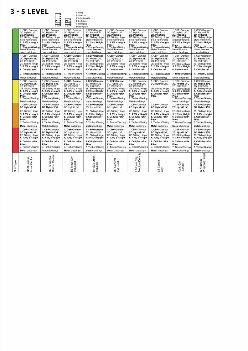
3 - 5 LEVEL 1. Bracing
2. Connections
3. Timber Shear Wall
4. Base Isolation
5. Building Gap
6. Cladding Types
B 1 - B u s i n e s s
L o c a l C e n t r e
B 2 - B u s i n e s s
D i s t r i c t C e n t r e
B 3 - I n n e r C i t y
I n d u s t r i a l
B 4 - S u b u r b a n
I n d u s t r i a
B 5 - G e n e r a l
I n d u s t r i a l
L 3 - I n n e r C i t y ,
M e d i u m D
e n s i t y
L 4 - C e n t r a l
C i t y
C u 3 ,
C u 4
S c h o o l
S P - S p e c i a l
P u r p o s e ( H o s p )
S o i l T y p e s
Piles7. Timber/GlazingMetal/ Precast
conc claddings
5. 2.5% x HeightSteel reinforcing
Piles7. Timber/GlazingMetal/ Precast
conc claddings
5. 2.5% x HeightSteel reinforcing
Piles7. Timber/GlazingMetal/ Precast
conc claddings
5. 2.5% x HeightSteel reinforcing
7. Timber/GlazingMetal/ Precast
conc claddings
5. 2.5% x HeightSteel reinforcing
7. Timber/GlazingMetal/ Precast
conc claddings
5. 2.5% x HeightSteel reinforcing
7. Timber/GlazingMetal/ Precast
conc claddings
5. 2.5% x HeightSteel reinforcing
7. Timber/GlazingMetal/ Precast
conc claddings
Steel reinforcing
2C. Hybrid LVL 2C. Hybrid LVL 2C. Hybrid LVL2D. PRESSS 2D. PRESSS 2D. PRESSS
5. 2.5% x Height
1. CBF+Damper 1. CBF+Damper 1. CBF+Damper
Piles Piles
2C. Hybrid LVL 2C. Hybrid LVL2D. PRESSS 2D. PRESSS
1. CBF+Damper 1. CBF+Damper 2C. Hybrid LVL2D. PRESSS
1. CBF+Damper 2C. Hybrid LVL2D. PRESSS
1. CBF+Damper
Piles PilesPiles7. Timber/GlazingMetal/ Precast
conc claddings
5. 2.5% x HeightSteel reinforcing
2C. Hybrid LVL1. CBF+Damper
2D. PRESSS
Piles7. Timber/GlazingMetal/ Precast
conc claddings
5. 2.5% x HeightSteel reinforcing
2C. Hybrid LVL2D. PRESSS
1. CBF+Damper
6. Cellular raft 6. Cellular raft 6. Cellular raft 6. Cellular raft 6. Cellular raft
2C. Hybrid LVL 2C. Hybr id LVL 2C. Hybr id LVL2D. PRESSS 2D. PRESSS2D. PRESSS
1. CBF+Damper 1. CBF+Damper 1. CBF+Damper 2C. Hybrid LVL2D. PRESSS
1. CBF+Damper 2C. Hybrid LVL2D. PRESSS
1. CBF+Damper 2C. Hybrid LVL2D. PRESSS
1. CBF+Damper
6. Cellular raft
2C. Hybrid LVL2D. PRESSS
1. CBF+Damper
6. Cellular raft
2C. Hybrid LVL2D. PRESSS
1. CBF+Damper
6. Cellular raft
5. 2.5% x Height 5. 2.5% x Height 5. 2.5% x Height 5. 2.5% x Height 5. 2.5% x Height 5. 2.5% x Height5. 2.5% x Height 5. 2.5% x Height
7. Timber/Glazing
Metal claddings
7. Timber/Glazing
Metal claddings
7. Timber/Glazing
Metal claddings
7. Timber/Glazing
Metal claddings
7. Timber/Glazing
Metal claddings
7. Timber/Glazing
Metal claddings
7. Timber/Glazing
Metal claddings
7. Timber/Glazing
Metal claddings
Metal claddings
7. Timber/Glazing
Metal claddings Metal claddings Metal claddings Metal claddings
7. Timber/Glazing
Metal claddings
7. Timber/Glazing
Metal claddings
7. Timber/Glazing
Metal claddings
7. Timber/Glazing
2C. Hybrid LVL 2C. Hybrid LVL 2C. Hybrid LVL 2C. Hybrid LVL1. CBF+Damper 1. CBF+Damper 1. CBF+Damper 1. CBF+Damper
2C. Hybrid LVL 2C. Hybrid LVL1. CBF+Damper 1. CBF+Damper
2C. Hybrid LVL 2C. Hybrid LVL1. CBF+Damper 1. CBF+Damper
6. Cellular raft+Piles
6. Cellular raft+Piles
6. Cellular raft+Piles
6. Cellular raft+Piles
7. Timber/Glazing
Metal claddings
2C. Hybrid LVL1. CBF+Damper
6. Cellular raft+Piles
6. Cellular raft+Piles
6. Cellular raft+Piles
6. Cellular raft+Piles
6. Cellular raft+Piles
5. 2.5% x Height 5. 2.5% x Height 5. 2.5% x Height 5. 2.5% x Height 5. 2.5% x Height 5. 2.5% x Height 5. 2.5% x Height5. 2.5% x Height 5. 2.5% x Height
7. Timber/Glazing 7. Timber/Glazing 7. Timber/Glazing
7. Timber/Glazing
Metal claddings
6. Cellular raft+
2C. Hybrid LVL 2C. Hybrid LVL 2C. Hybrid LVL 2C. Hybrid LVL2D. PRESSS 2D. PRESSS 2D. PRESSS2D. PRESSS
1. CBF+Damper 1. CBF+Damper 1. CBF+Damper 1. CBF+Damper 2C. Hybrid LVL 2C. Hybrid LVL
1. CBF+Damper 1. CBF+Damper 2C. Hybrid LVL 2C. Hybrid LVL
1. CBF+Damper 1. CBF+Damper
Piles6. Cellular raft+Piles
6. Cellular raft+Piles
6. Cellular raft+Piles
2C. Hybrid LVL2D. PRESSS
1. CBF+Damper
6. Cellular raft+Piles
6. Cellular raft+Piles
6. Cellular raft+Piles
6. Cellular raft+Piles
6. Cellular raft+Piles
5. 2.5% x Height 5. 2.5% x Height 5. 2.5% x Height 5. 2.5% x Height 5. 2.5% x Height 5. 2.5% x Height 5. 2.5% x Height5. 2.5% x Height 5. 2.5% x Height
7. Timber/Glazing
Metal claddings
7. Timber/Glazing
Metal claddings
7. Timber/Glazing
Metal claddings
7. Timber/Glazing
Metal claddings
7. Timber/Glazing
Metal claddings
7. Timber/Glazing
Metal claddings
7. Timber/Glazing
Metal claddings
2D. PRESSS 2D. PRESSS2D. PRESSS
7. Timber/Glazing 7. Timber/Glazing 7. Timber/Glazing 7. Timber/Glazing 7. Timber/Glazing 7. Timber/Glazing 7. Timber/Glazing
2C. Hybrid LVL 2C. Hybrid LVL 2C. Hybrid LVL
1. CBF+Damper 1. CBF+Damper 1. CBF+Damper
2C. Hybrid LVL 2C. Hybrid LVL
1. CBF+Damper 1. CBF+Damper
2C. Hybrid LVL 2C. Hybrid LVL
1. CBF+Damper 1. CBF+Damper
6. Cellular raft+
Piles
6. Cellular raft+
Piles
6. Cellular raft+
Piles7. Timber/Glazing
2C. Hybrid LVL
1. CBF+Damper
6. Cellular raft+
Piles7. Timber/Glazing
2C. Hybrid LVL
1. CBF+Damper
6. Cellular raft+
Piles
6. Cellular raft+
Piles
6. Cellular raft+
Piles
6. Cellular raft+
Piles
6. Cellular raft+
Piles
5. 2.5% x Height 5. 2.5% x Height 5. 2.5% x Height 5. 2.5% x Height 5. 2.5% x Height 5. 2.5% x Height 5. 2.5% x Height5. 2.5% x Height 5. 2.5% x Height
Metal claddings Metal claddings Metal claddings Metal claddings Metal claddings Metal claddings Metal claddings Metal claddingsMetal claddings
2E. Sliding Hinge 2E. Sliding Hinge 2E. Sliding Hinge 2E. Sliding Hinge 2E. Sliding Hinge 2E. Sliding Hinge 2E. Sliding Hinge 2E. Sliding Hinge 2E. Sliding Hinge
2E. Sliding Hinge 2E. Sliding Hinge 2E. Sliding Hinge 2E. Sliding Hinge 2E. Sliding Hinge 2E. Sliding Hinge 2E. Sliding Hinge 2E. Sliding Hinge
2E. Sliding Hinge 2E. Sliding Hinge 2E. Sliding Hinge 2E. Sliding Hinge 2E. Sliding Hinge 2E. Sliding Hinge 2E. Sliding Hinge 2E. Sliding Hinge 2E. Sliding Hinge
2E. Sliding Hinge 2E. Sliding Hinge 2E. Sliding Hinge 2E. Sliding Hinge 2E. Sliding Hinge 2E. Sliding Hinge 2E. Sliding Hinge 2E. Sliding Hinge 2E. Sliding Hinge
2E. Sliding Hinge 2E. Sliding Hinge 2E. Sliding Hinge 2E. Sliding Hinge 2E. Sliding Hinge 2E. Sliding Hinge 2E. Sliding Hinge 2E. Sliding Hinge 2E. Sliding Hinge
2C. Hybrid LVL2D. PRESSS
1. CBF+Damper
6. Cellular raft
5. 2.5% x Height
7. Timber/Glazing
Metal claddings
2E. Sliding Hinge
7/30/2019 121101 Kp Ppt Final
http://slidepdf.com/reader/full/121101-kp-ppt-final 42/122
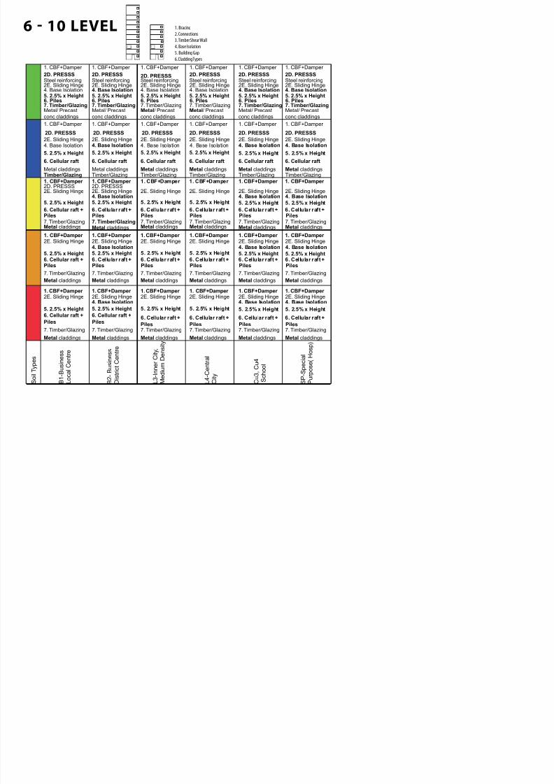
6 - 10 LEVEL 1. Bracing
2. Connections
3. Timber Shear Wall
4. Base Isolation
5. Building Gap
6. Cladding Types
B 1 - B u s i n e s s
L o c a l C e n t r e
B 2 - B u s i n e s s
D i s t r i c t C e n t r e
L 3 - I n n e r C i t y ,
M e d i u m D
e n s i t y
L 4 - C e n t r a l
C i t y
C u 3 ,
C u 4
S c h o o l
S P - S p e c i a l
P u r p o s e ( H o s p )
S o i l T y p e s
6. Piles7. Timber/GlazingMetal/ Precast
conc claddings
5. 2.5% x Height
Steel reinforcing
7. Timber/GlazingMetal/ Precast
conc claddings
5. 2.5% x Height
Steel reinforcing
7. Timber/GlazingMetal/ Precast
conc claddings
5. 2.5% x Height
Steel reinforcing
7. Timber/GlazingMetal/ Precast
conc claddings
5. 2.5% x Height
Steel reinforcing
7. Timber/GlazingMetal/ Precast
conc claddings
Steel reinforcing2D. PRESSS
5. 2.5% x Height
1. CBF+Damper
6. Piles 6. Piles
2D. PRESSS 2D. PRESSS
1. CBF+Damper 1. CBF+Damper
2D. PRESSS
1. CBF+Damper
2D. PRESSS
1. CBF+Damper
6. Piles 6. Piles
4. Base Isolation
6. Piles7. Timber/GlazingMetal/ Precast
conc claddings
5. 2.5% x Height
Steel reinforcing
1. CBF+Damper
2D. PRESSS
4. Base Isolation4. Base Isolation4. Base Isolation4. Base Isolation4. Base Isolation
6. Cellular raft
Metal claddings Metal claddings
6. Cellular raft
Metal claddings
6. Cellular raft
Metal claddings
2D. PRESSS
1. CBF+Damper 1. CBF+Damper
2D. PRESSS
1. CBF+Damper
2D. PRESSS
1. CBF+Damper
6. Cellular raft
Metal claddings
2D. PRESSS
1. CBF+Damper
4. Base Isolation
6. Cellular raft
4. Base Isolation 4. Base Isolation
5. 2.5% x Height 5. 2.5% x Height 5. 2.5% x Height 5. 2.5% x Height5. 2.5% x Height
2D. PRESSS
4. Base Isolation 4. Base Isolation4. Base Isolation
6. Cellular raft +
Metal claddings7. Timber/Glazing
Metal claddings7. Timber/Glazing
Metal claddings7. Timber/Glazing
Metal claddings7. Timber/Glazing
Metal claddings7. Timber/Glazing
2D. PRESSS1. CBF+Damper 1. CBF+Damper 1. CBF+Damper
7. Timber/GlazingMetal claddings
2D. PRESSS1. CBF+Damper
4. Base Isolation
6. Cellular raft + 6. Cellular raft + 6. Cellular raft + 6. Cellular raft + 6. Cellular raft +
4. Base Isolation 4. Base Isolation5. 2.5% x Height 5. 2.5% x Height 5. 2.5% x Height 5. 2.5% x Height 5. 2.5% x Height5. 2.5% x Height
1. CBF+Damper 1. CBF+Damper
Metal claddings
7. Timber/Glazing
Metal claddings
7. Timber/Glazing
Metal claddings
7. Timber/Glazing
Metal claddings
7. Timber/Glazing
Metal claddings
7. Timber/Glazing
1. CBF+Damper 1. CBF+Damper 1. CBF+Damper
6. Cellular raft +
7. Timber/Glazing
Metal claddings
1. CBF+Damper
4. Base Isolation
6. Cellular raft + 6. Cellular raft + 6. Cellular raft + 6. Cellular raft + 6. Cellular raft +
4. Base Isolation 4. Base Isolation5. 2.5% x Height 5. 2.5% x Height 5. 2.5% x Height 5. 2.5% x Height 5. 2.5% x Height5. 2.5% x Height
1. CBF+Damper 1. CBF+Damper
Metal claddings
7. Timber/Glazing
Metal claddings
7. Timber/Glazing
Metal claddings
7. Timber/Glazing
Metal claddings
7. Timber/Glazing
1. CBF+Damper 1. CBF+Damper
Metal claddings
7. Timber/Glazing
1. CBF+Damper
6. Cellular raft +
7. Timber/Glazing
Metal claddings
1. CBF+Damper
4. Base Isolation
6. Cellular raft + 6. Cellular raft + 6. Cellular raft + 6. Cellular raft + 6. Cellular raft +
4. Base Isolation 4. Base Isolation
5. 2.5% x Height 5. 2.5% x Height 5. 2.5% x Height 5. 2.5% x Height 5. 2.5% x Height5. 2.5% x Height
1. CBF+Damper 1. CBF+Damper
2E. Sliding Hinge 2E. Sliding Hinge 2E. Sliding Hinge 2E. Sliding Hinge 2E. Sliding Hinge
2E. Sliding Hinge 2E. Sliding Hinge 2E. Sliding Hinge 2E. Sliding Hinge 2E. Sliding Hinge 2E. Sliding Hinge
2E. Sliding Hinge 2E. Sliding Hinge 2E. Sliding Hinge 2E. Sliding Hinge 2E. Sliding Hinge 2E. Sliding Hinge
2E. Sliding Hinge 2E. Sliding Hinge 2E. Sliding Hinge 2E. Sliding Hinge 2E. Sliding Hinge 2E. Sliding Hinge
2E. Sliding Hinge 2E. Sliding Hinge 2E. Sliding Hinge 2E. Sliding Hinge 2E. Sliding Hinge 2E. Sliding Hinge
Timber/Glazing Timber/Glazing Timber/Glazing Timber/GlazingTimber/GlazingMetal claddings
1. CBF+Damper
6. Cellular raft
5. 2.5% x Height
2D. PRESSS
2E. Sliding Hinge
Timber/Glazing
Piles Piles Piles Piles Piles Piles
Piles Piles Piles Piles Piles Piles
Piles Piles Piles Piles Piles Piles
7/30/2019 121101 Kp Ppt Final
http://slidepdf.com/reader/full/121101-kp-ppt-final 43/122
EXTRUSION OF POSSIBLE BUILT
CHRISTCHURCH’S BUILDING ENVELOPE
7/30/2019 121101 Kp Ppt Final
http://slidepdf.com/reader/full/121101-kp-ppt-final 44/122
CHRISTCHURCH’S BUILDING ENVELOPE
Building Area
Christchurch’s Building Envelope
CBD
CHRISTCHURCH’S BUILDING ENVELOPE

7/30/2019 121101 Kp Ppt Final
http://slidepdf.com/reader/full/121101-kp-ppt-final 45/122
6+ Level - living inner city, living central city, medium density, business district centre,
3 - 5 Level - general industrial, school, special purpose,hospital, living inner suburban
3 - 5 Level - inner city industrial, business local centre
1 - 2 Level - school, hospital, sub urban industrial, general industrial
1 - 2 Level - business local centre, school, hospital, living inner city
1 Level - Living inner city, living suburban, business local centre, business district centre
Single storey - school, hospital, general industrial
Single storey - school, hospital, business local centre, living inner city, living inner suburban, general
industrial
CHRISTCHURCH’S BUILDING ENVELOPE
Extrusion o Possible Built Area Relative to the Suggested Maximum Structural Height and Soil Type
CBD: Extrusion o Possible Built Area

7/30/2019 121101 Kp Ppt Final
http://slidepdf.com/reader/full/121101-kp-ppt-final 46/122
MOVING STRUCTURES FOUND IN NATURE
7/30/2019 121101 Kp Ppt Final
http://slidepdf.com/reader/full/121101-kp-ppt-final 47/122
Glass Sponge(from Weaver, 2007)
Dragony Hind Wing(from Podor, 2012)
Seahorse(from Praet, 2012)
Threespine Stickleback (from Song, 2010)
Chiton Shell(from Connors, 2012)
Mussel(from Zinkova, 2012)

7/30/2019 121101 Kp Ppt Final
http://slidepdf.com/reader/full/121101-kp-ppt-final 48/122
GLASS SPONGE
THE NATIVE SKELETAL LATTICE
7/30/2019 121101 Kp Ppt Final
http://slidepdf.com/reader/full/121101-kp-ppt-final 49/122
THE NATIVE SKELETAL LATTICE
Woven Glass Fibres(from Fratzl, 2007)
The Square Grid Architecture(from Fratzl, 2007)
The Native Skeletal Lattice(from Weaver, 2007)
Arrangement o a Square Network to Stif in Shear(from Currey, 2005)
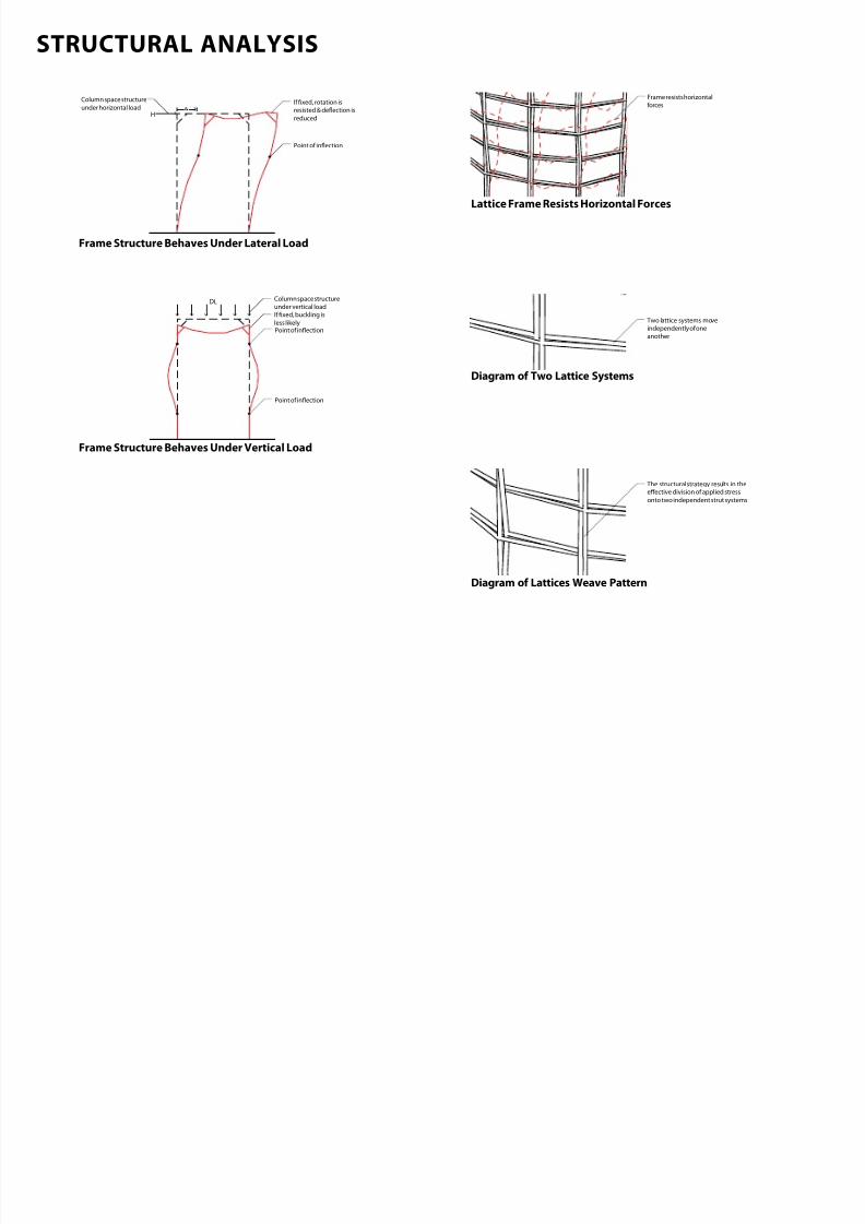
STRUCTURAL ANALYSIS
7/30/2019 121101 Kp Ppt Final
http://slidepdf.com/reader/full/121101-kp-ppt-final 50/122
The structural strategy results in theefective division o applied stress
onto two independent strut systems
H
Column space structure
under horizontal loadIf xed, rotation is
resisted & deection is
reduced
Point of inection
DL
Point of inection
If xed, buckling is
less likely
Point of inection
Column space structure
under vertical load
Frame resists horizontalorces
Two lattice systems moveindependently o oneanother
STRUCTURAL ANALYSIS
Frame Structure Behaves Under Lateral Load
Frame Structure Behaves Under Vertical Load
Lattice Frame Resists Horizontal Forces
Diagram o Two Lattice Systems
Diagram o Lattices Weave Pattern
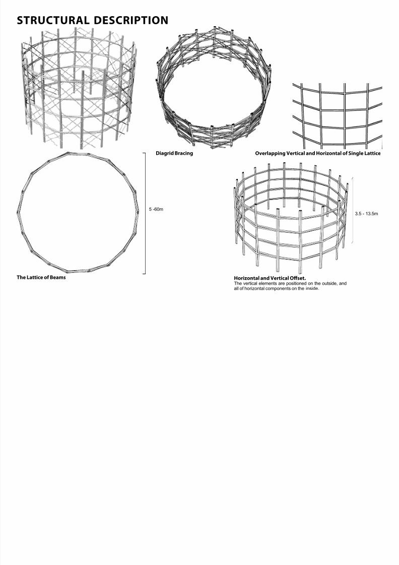
STRUCTURAL DESCRIPTION
7/30/2019 121101 Kp Ppt Final
http://slidepdf.com/reader/full/121101-kp-ppt-final 51/122
STRUCTURAL DESCRIPTION
Overlapping Vertical and Horizontal o Single Lattice
The Lattice o BeamsHorizontal and Vertical Ofset.The vertical elements are positioned on the outside, andall of horizontal components on the inside.
Diagrid Bracing
3.5 - 13.5m5 -60m
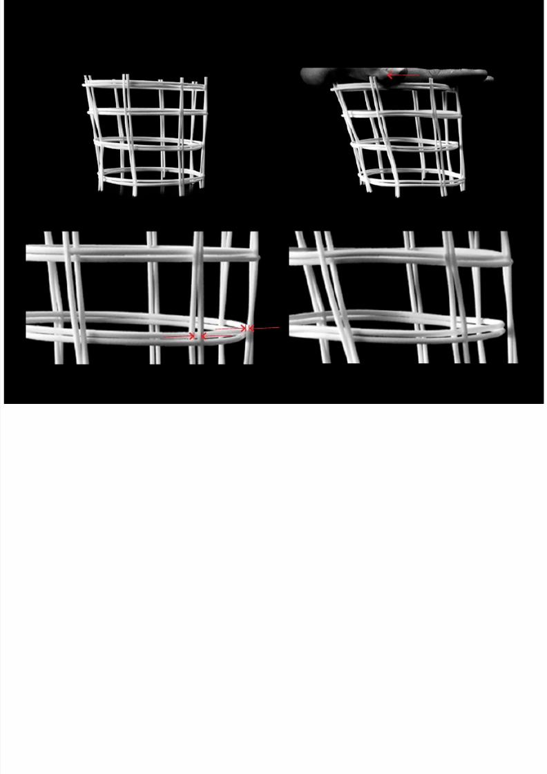
STRUCTURAL MOVEMENT
7/30/2019 121101 Kp Ppt Final
http://slidepdf.com/reader/full/121101-kp-ppt-final 52/122
STRUCTURAL MOVEMENT
Image o a Lattice Frame Image o a Lattice Frame Under Lateral Load
Zoom in Image o a Lattice Frame in Rest Position Zoom in Image o a Lattice Frame in Movement Position
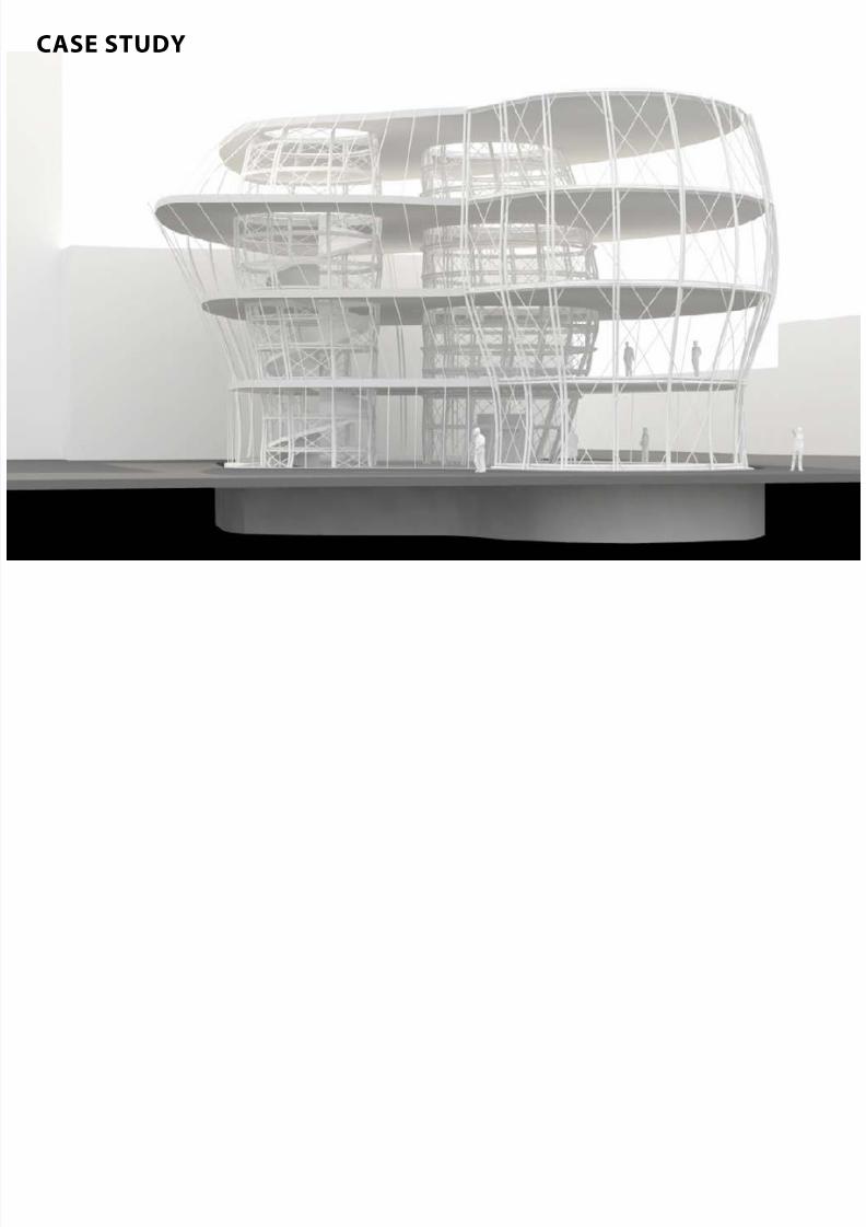
CASE STUDY
7/30/2019 121101 Kp Ppt Final
http://slidepdf.com/reader/full/121101-kp-ppt-final 53/122
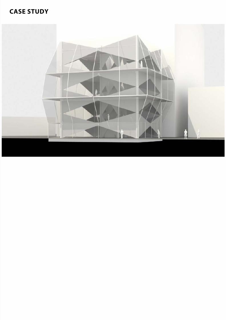
CASE STUDY
CASE STUDY
7/30/2019 121101 Kp Ppt Final
http://slidepdf.com/reader/full/121101-kp-ppt-final 54/122
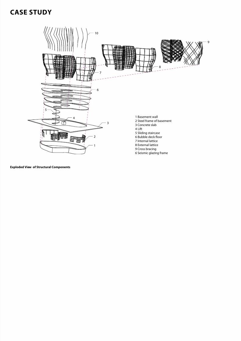
1 Basement wall
2 Steel frame of basement
3 Concrete slab
4 Lift5 Sliding staircase
6 Bubble deck oor
7 Internal lattice
8 External lattice
9 Cross bracing
6 Seismic glazing frame
8
9
10
6
7
5
2
4
1
3
CASE STUDY
Exploded View o Structural Components
CASE STUDY
7/30/2019 121101 Kp Ppt Final
http://slidepdf.com/reader/full/121101-kp-ppt-final 55/122
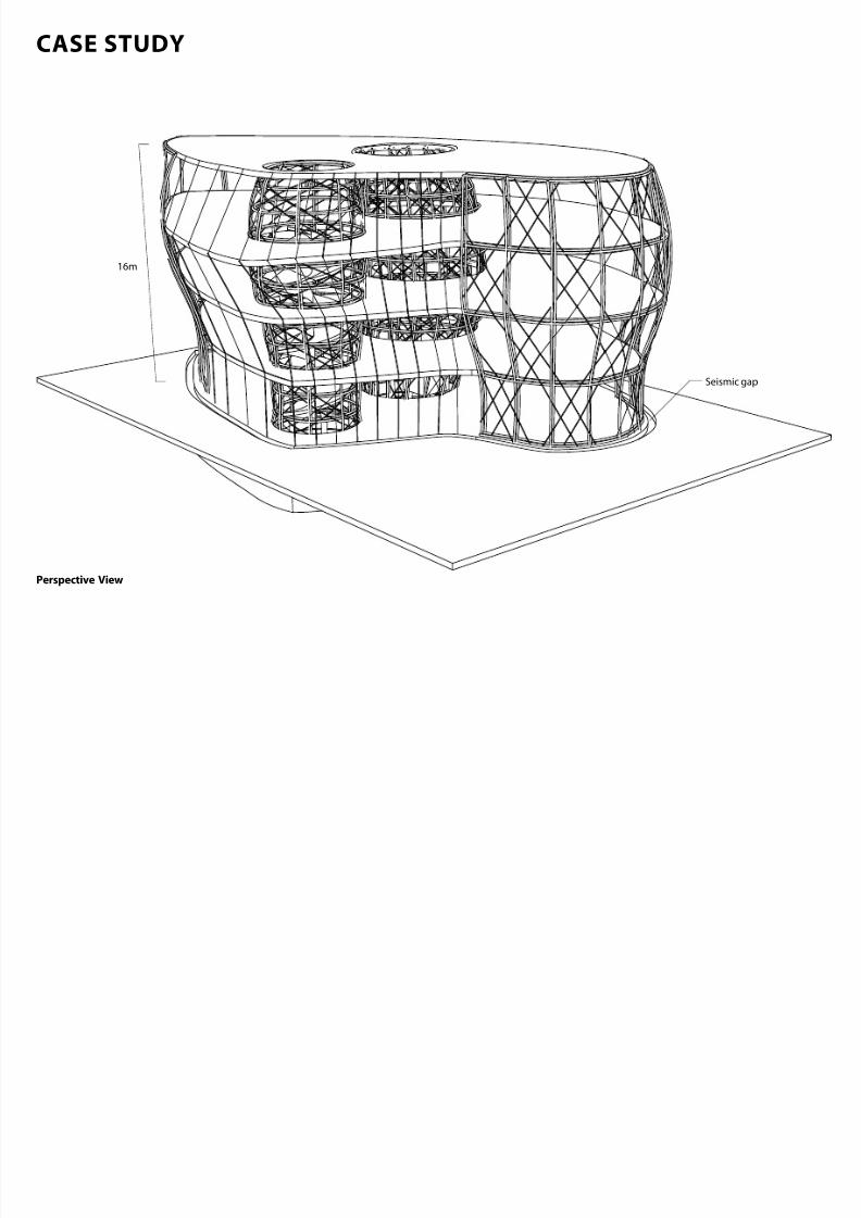
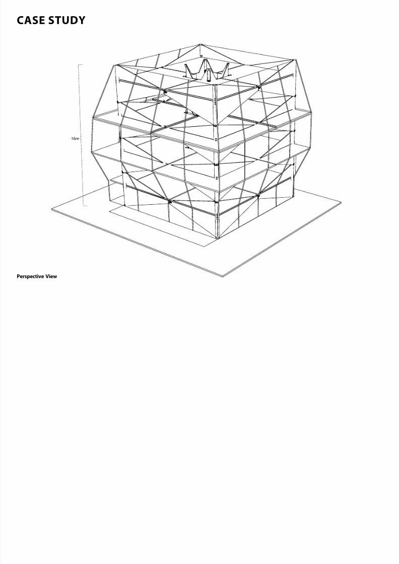
16m
Seismic gap
CASE STUDY
Perspective View
7/30/2019 121101 Kp Ppt Final
http://slidepdf.com/reader/full/121101-kp-ppt-final 56/122
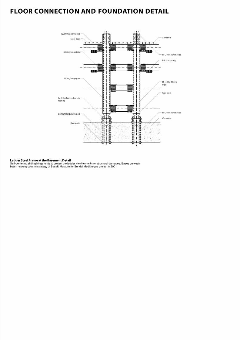
FLOOR CONNECTION AND FOUNDATION DETAIL
7/30/2019 121101 Kp Ppt Final
http://slidepdf.com/reader/full/121101-kp-ppt-final 57/122
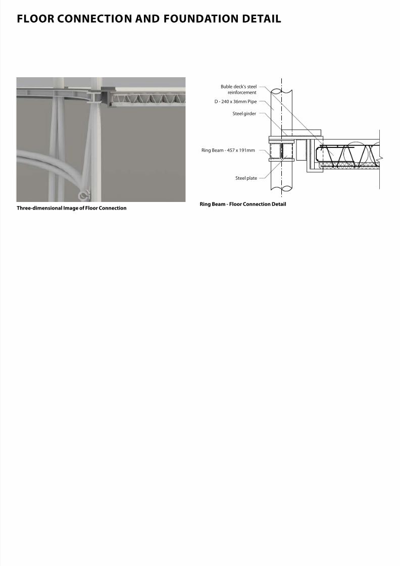
D - 240 x 36mm Pipe
Ring Beam - 457 x 191mm
Buble deck’s steel
reinforcement
Steel girder
Steel plate
FLOOR CONNECTION AND FOUNDATION DETAIL
Ring Beam Floor Connection DetailThreedimensional Image o Floor Connection
FLOOR CONNECTION AND FOUNDATION DETAIL
7/30/2019 121101 Kp Ppt Final
http://slidepdf.com/reader/full/121101-kp-ppt-final 58/122
Cast steel
Friction spring
D - 400 x 45mm
Pipe
Sliding hinge joint
100mm concrete top
Concrete
6 x M64 Hold down bolt
Cast steel pins allows for
rocking
D - 240 x 36mm Pipe
Stud bolt
D - 240 x 36mm Pipe
Base plate
Steel deck
Sliding hinge joint
FLOOR CONNECTION AND FOUNDATION DETAIL
Ladder Steel Frame at the Basement DetailSelf-centering sliding hinge joints to protect the ladder steel frame from structural damages. Bases on weakbeam - strong column strategy of Sasaki Mutsuro for Sendai Meditheque project in 2001
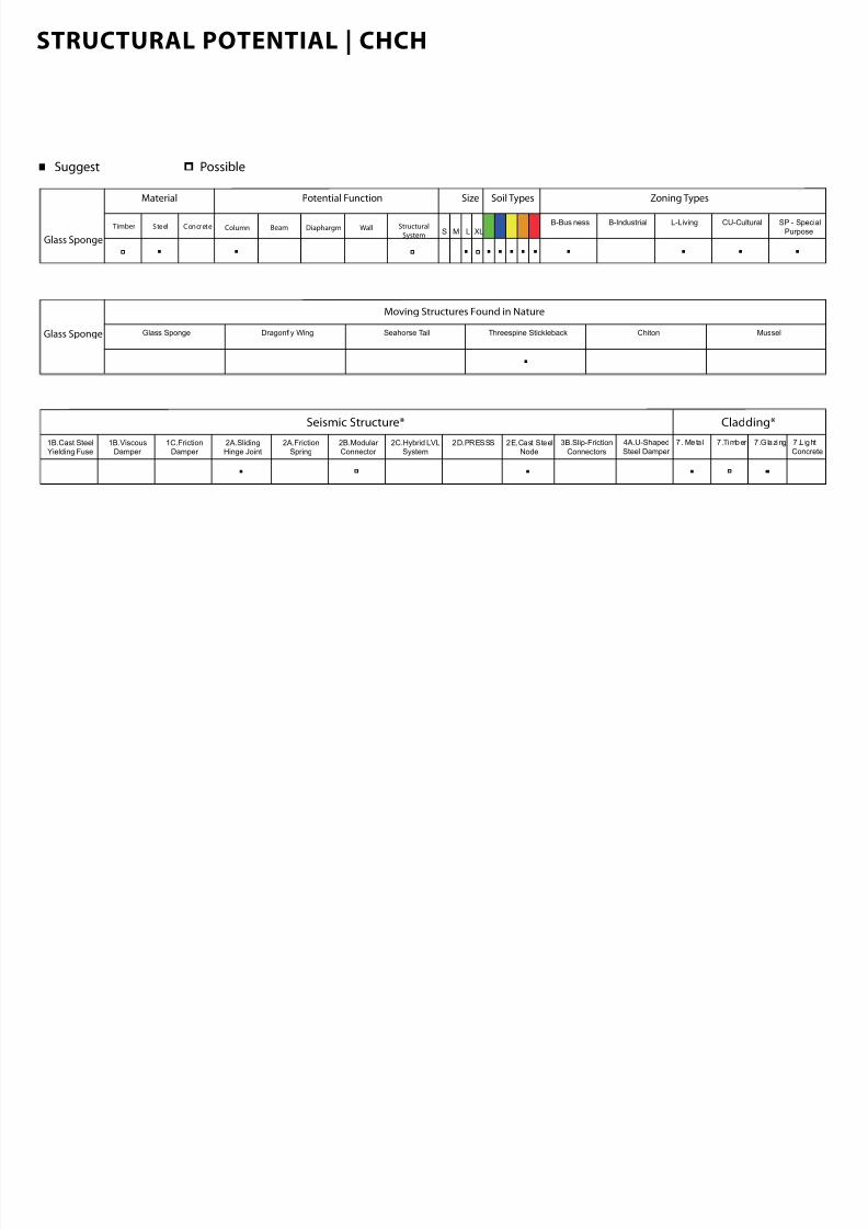
STRUCTURAL POTENTIAL | CHCH
7/30/2019 121101 Kp Ppt Final
http://slidepdf.com/reader/full/121101-kp-ppt-final 59/122
Material
Timber Steel Concrete
Soil Types Zoning Types
B-Business B-Industrial SP - Special
Purpose
L-Living CU-Cultural
Potential Function Size
S M L XLColumn Beam WallDiaphargm Structural
SystemGlass Sponge
Seismic Structure* Cladding*
1B.Cast SteelYielding Fuse
1B.ViscousDamper
2A.FrictionSpring
1C.FrictionDamper
2A.SlidingHinge Joint
2B.Modular Connector
2C.Hybrid LVLSystem
2D.PRESSS 2E.Cast SteelNode
3B.Slip-Friction
Connectors
4A.U-Shaped
Steel Damper
7 . Meta l 7 .Timber 7.Glazing 7.L ight
Concrete
Suggest Possible
Glass Sponge Glass Sponge Dragonfly Wing ChitonSeahorse Tail Threespine Stickleback Mussel
Moving Structures Found in Nature
STRUCTURAL POTENTIAL | CHCH

7/30/2019 121101 Kp Ppt Final
http://slidepdf.com/reader/full/121101-kp-ppt-final 60/122
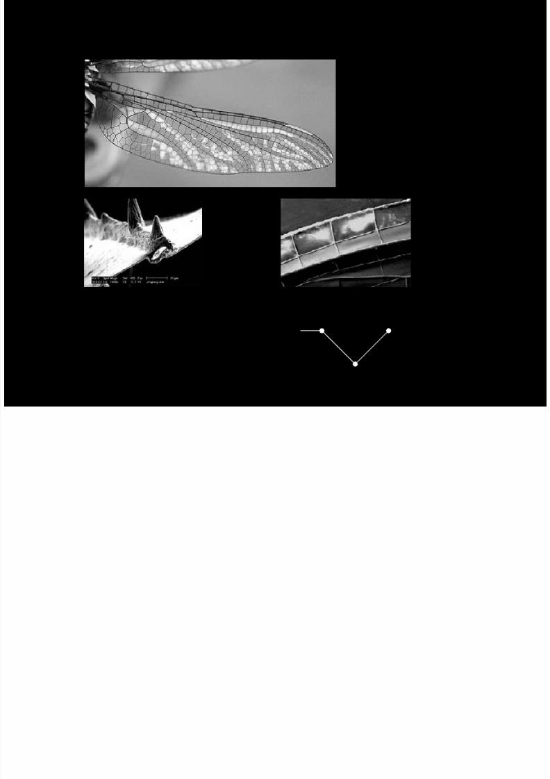
DRAGONFLY WING
DRAGONFLY HIND WING
7/30/2019 121101 Kp Ppt Final
http://slidepdf.com/reader/full/121101-kp-ppt-final 61/122
DRAGONFLY HIND WING
junction o The Vein and Membrane Pieces(from Li, 2009) Maor Frame(from Chen, 2010)
Maor Frame Section(from Chen, 2010)
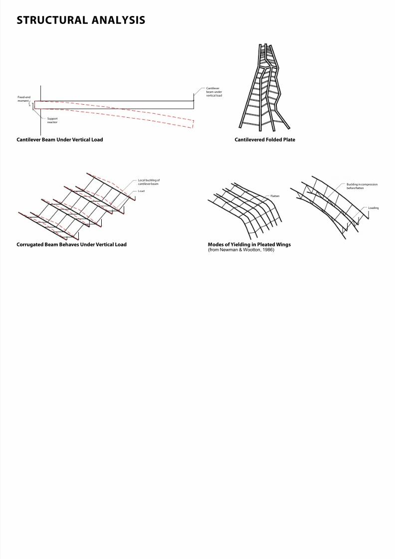
STRUCTURAL ANALYSIS
7/30/2019 121101 Kp Ppt Final
http://slidepdf.com/reader/full/121101-kp-ppt-final 62/122
STRUCTURAL ANALYSIS
Load
Local buckling of
cantilever beam
Cantilever
beam under
vertical load
Support
reaction
Fixed-end
moment
Loading
Buckling in compression
before atten
Flatten
Cantilever Beam Under Vertical Load Cantilevered Folded Plate
Corrugated Beam Behaves Under Vertical Load Modes o Yielding in Pleated Wings(from Newman & Wootton, 1986)
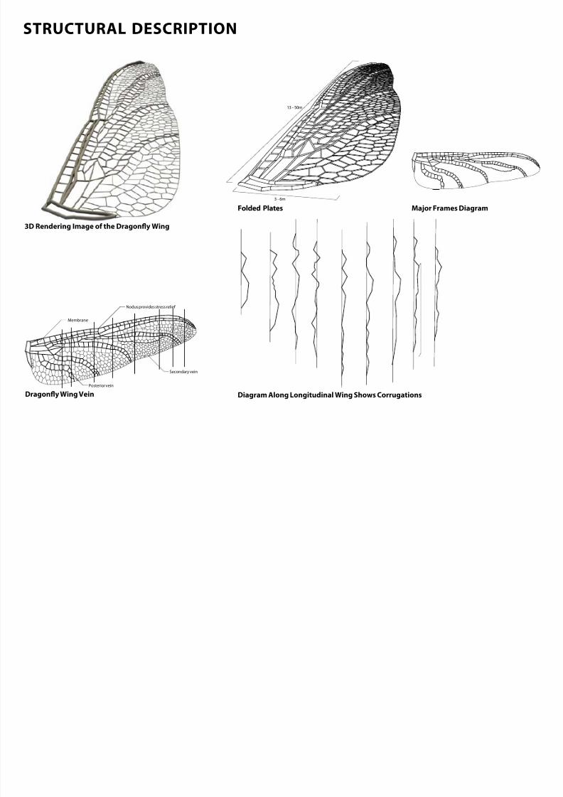
STRUCTURAL DESCRIPTION
7/30/2019 121101 Kp Ppt Final
http://slidepdf.com/reader/full/121101-kp-ppt-final 63/122
STRUCTURAL DESCRIPTION
3 - 6m
13 - 50m
Membrane
Posterior vein
Nodus provides stress relie
Secondary vein
Folded Plates
Dragony Wing Vein Diagram Along Longitudinal Wing Shows Corrugations
Maor Frames Diagram
3D Rendering Image o the Dragony Wing
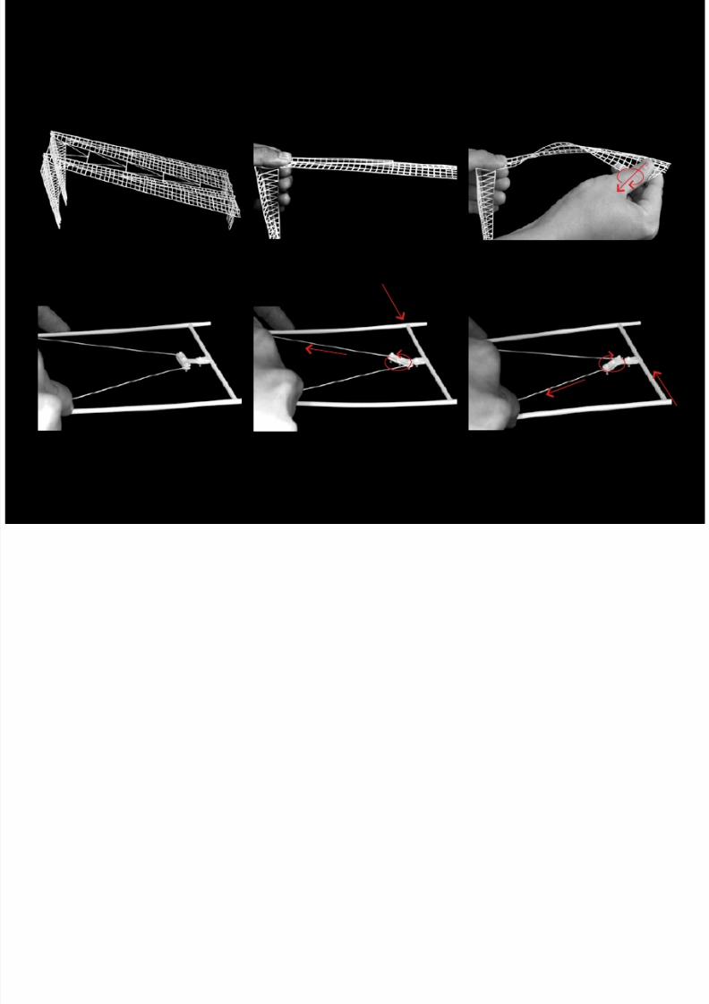
STRUCTURAL MOVEMENT
7/30/2019 121101 Kp Ppt Final
http://slidepdf.com/reader/full/121101-kp-ppt-final 64/122
STRUCTURAL MOVEMENT
Image o the Friction Damper Bracing at Center Bracing Under Forward Lateral Load
Image o Steel Frame Modular Image o a Steel Frame Cantilever
Bracing Under Reverse Lateral Load
Image o a Steel Frame Cantilever Under Lateral Force
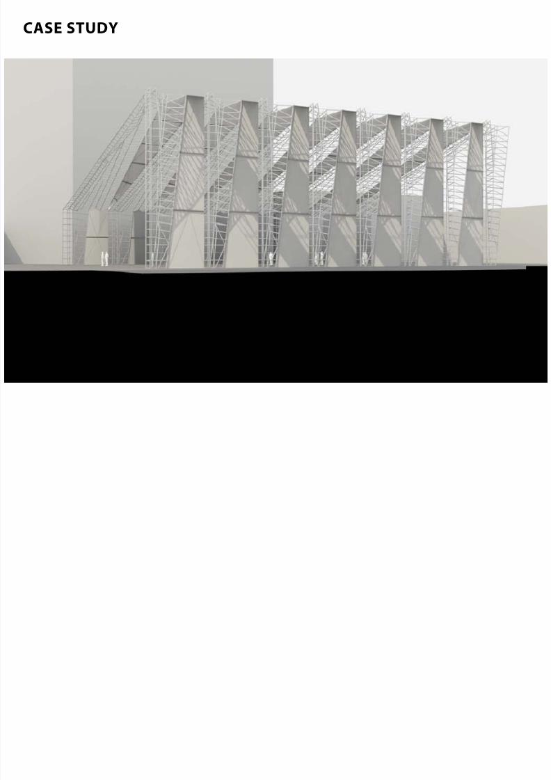
CASE STUDY
7/30/2019 121101 Kp Ppt Final
http://slidepdf.com/reader/full/121101-kp-ppt-final 65/122
CASE STUDY
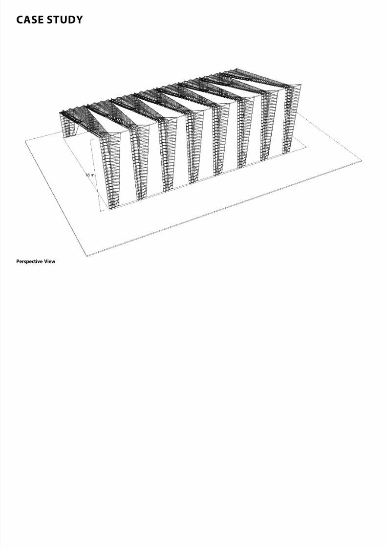
CASE STUDY
7/30/2019 121101 Kp Ppt Final
http://slidepdf.com/reader/full/121101-kp-ppt-final 66/122
16 m
CASE STUDY
Perspective View
CASE STUDY
7/30/2019 121101 Kp Ppt Final
http://slidepdf.com/reader/full/121101-kp-ppt-final 67/122
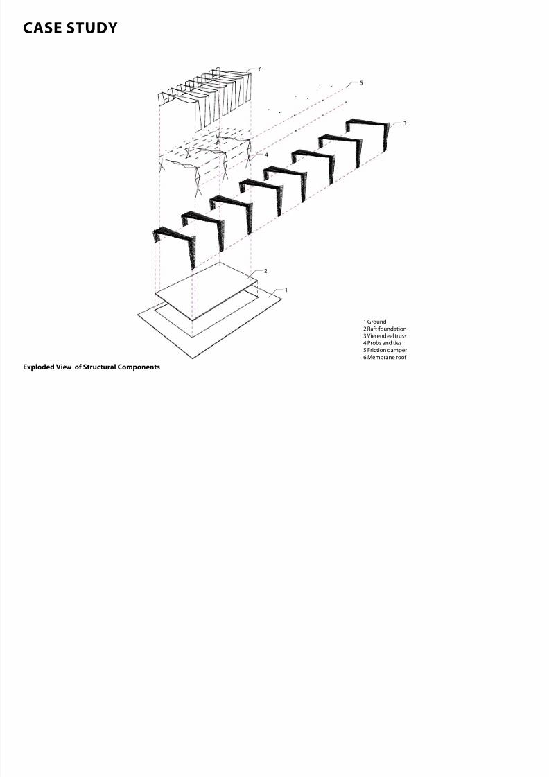
6
2
1 Ground
2 Raft foundation
3 Vierendeel truss
4 Probs and ties
5 Friction damper
6 Membrane roof
4
1
3
5
CASE STUDY
Exploded View o Structural Components
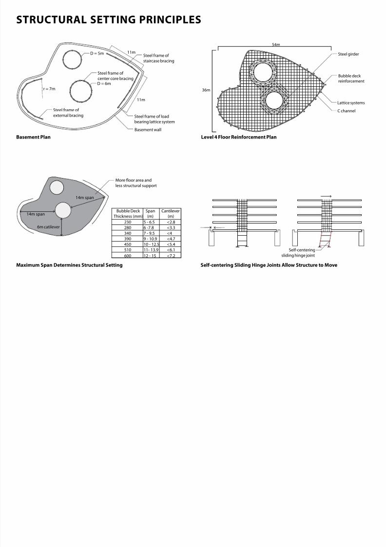
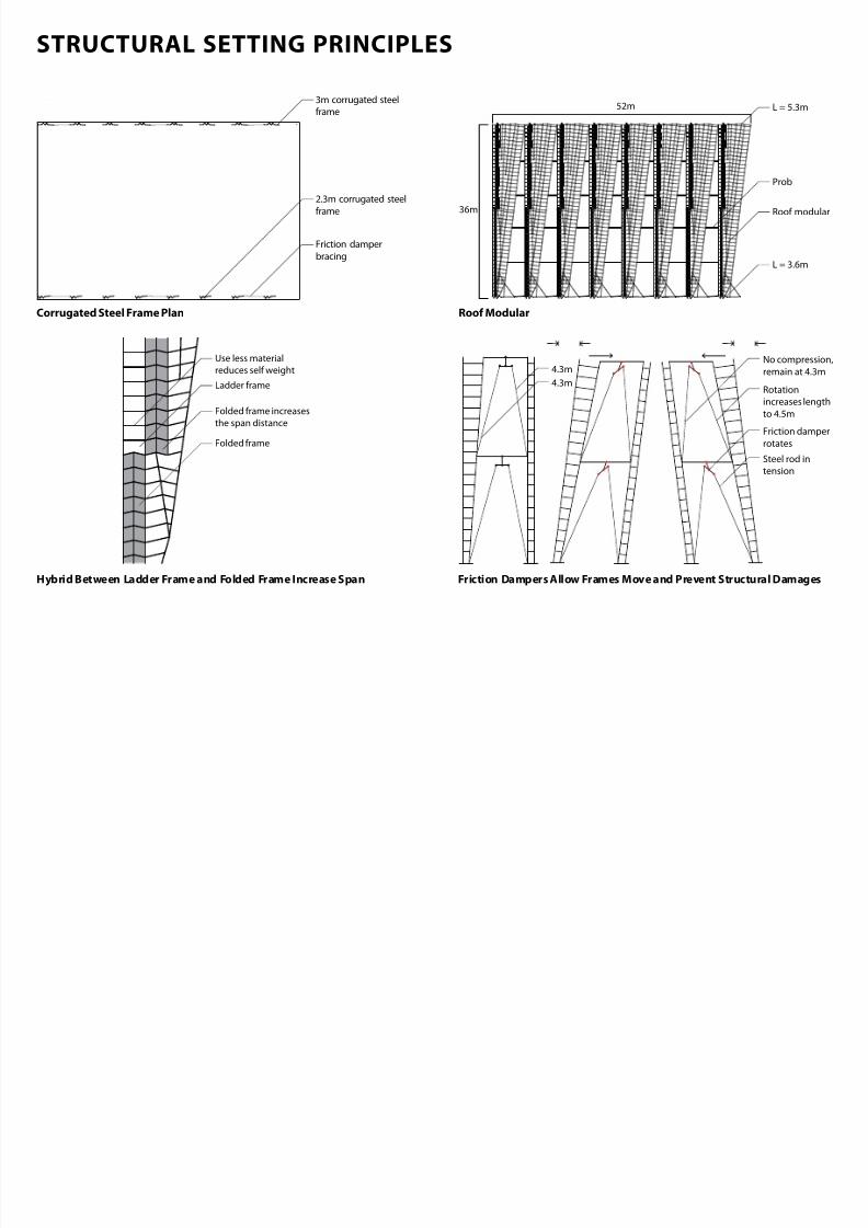
STRUCTURAL SETTING PRINCIPLES
7/30/2019 121101 Kp Ppt Final
http://slidepdf.com/reader/full/121101-kp-ppt-final 68/122
3m corrugated steel
frame
Friction damper
bracing
2.3m corrugated steel
frame
52m
Prob
36m Roof modular
L = 5.3m
L = 3.6m
Rotation
increases length
to 4.5m
Friction damper
rotates
Steel rod intension
4.3m
4.3m
No compression,
remain at 4.3m
Folded frame increases
the span distance
Use less material
reduces self weight
Folded frame
Ladder frame
Roo ModularCorrugated Steel Frame Plan
Hybrid Between Ladder Frame and Folded Frame Increase Span Friction Dampers Allow Frames Move and Prevent Structural Damages
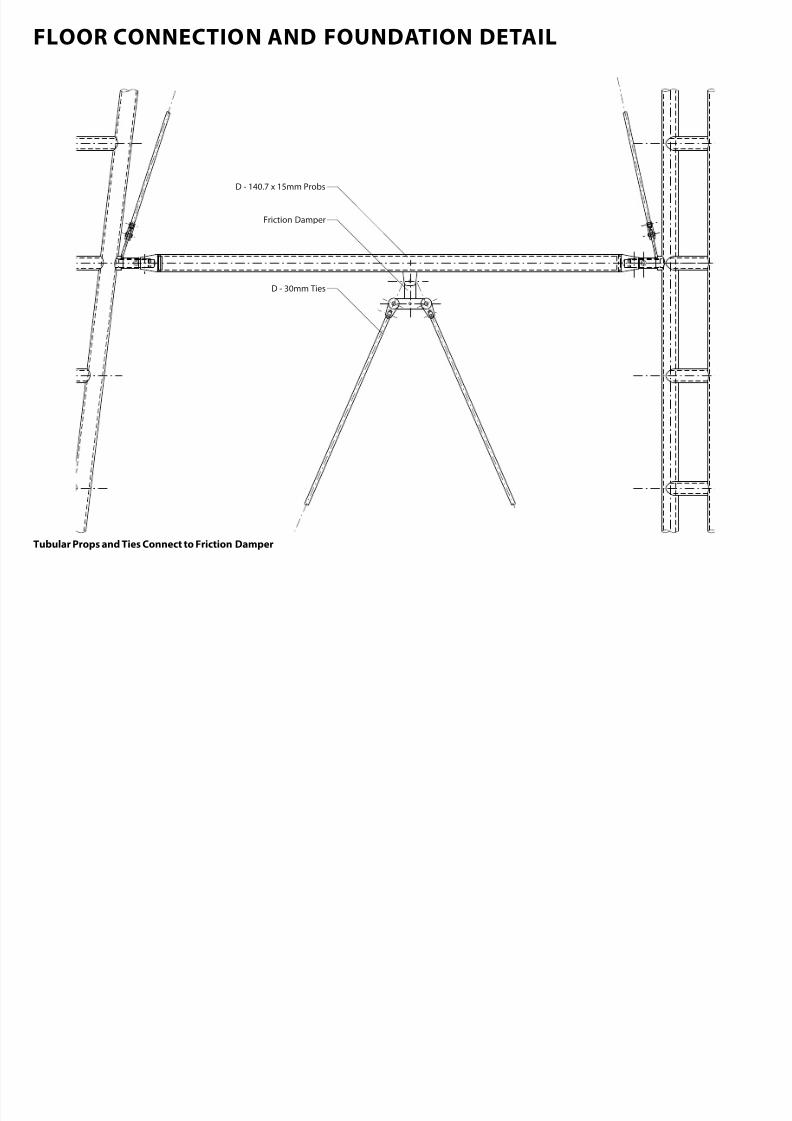
FLOOR CONNECTION AND FOUNDATION DETAIL
7/30/2019 121101 Kp Ppt Final
http://slidepdf.com/reader/full/121101-kp-ppt-final 69/122
D - 140.7 x 15mm Probs
Friction Damper
D - 30mm Ties
Tubular Props and Ties Connect to Friction Damper
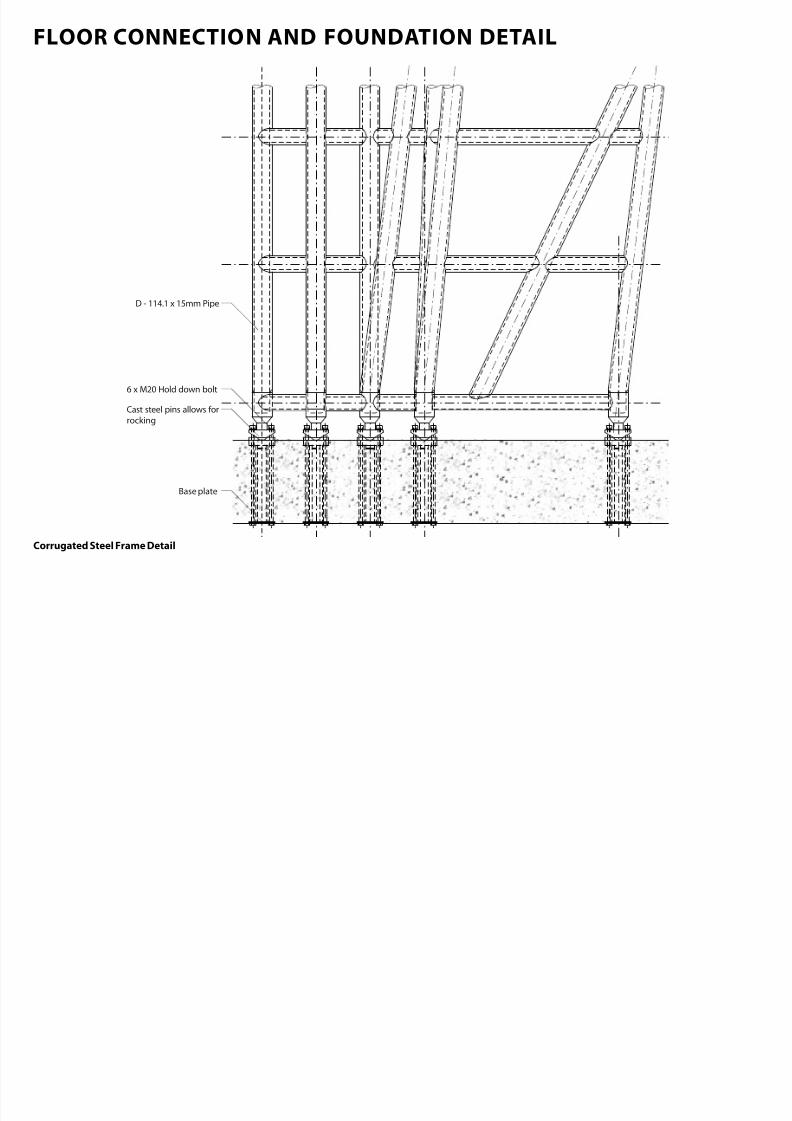
FLOOR CONNECTION AND FOUNDATION DETAIL
7/30/2019 121101 Kp Ppt Final
http://slidepdf.com/reader/full/121101-kp-ppt-final 70/122
6 x M20 Hold down bolt
Cast steel pins allows for
rocking
D - 114.1 x 15mm Pipe
Base plate
Corrugated Steel Frame Detail
STRUCTURAL POTENTIAL | CHCH

7/30/2019 121101 Kp Ppt Final
http://slidepdf.com/reader/full/121101-kp-ppt-final 71/122
Suggest Possible
Material
Timber Steel Concrete
Soil Types Zoning Types
B-Business B-Industrial SP - Special
Purpose
L-Living CU-Cultural
Potential Function Size
S M L XLColumn Beam WallDiaphargm Structural
SystemDragonyWing
Seismic Structure* Cladding*
1B.Cast SteelYielding Fuse
1B.ViscousDamper
2A.FrictionSpring
1C.FrictionDamper
2A.SlidingHinge Joint
2B.Modular Connector
2C.Hybrid LVLSystem
2D.PRESSS 2E.Cast SteelNode
3B.Slip-Friction
Connectors
4A.U-Shaped
Steel Damper
7 . Meta l 7 .Timber 7.Glazing 7.L ight
Concrete
Dragony
Wing
Glass Sponge Dragonfly Wing ChitonSeahorse Tail Threespine Stickleback Mussel
Moving Structures Found in Nature

7/30/2019 121101 Kp Ppt Final
http://slidepdf.com/reader/full/121101-kp-ppt-final 72/122
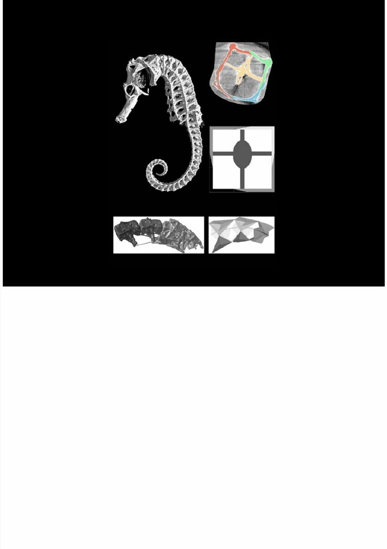
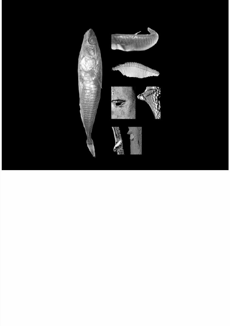
SEAHORSE TAIL
SEAHORSE TAIL
7/30/2019 121101 Kp Ppt Final
http://slidepdf.com/reader/full/121101-kp-ppt-final 73/122
The Skeletal Elements rom the CT Scans(from Praet, 2012)
Modeled Tail Bending Muscles(from Praet, 2012)
The Median Ventral Muscles(from Praet, 2012)
Simplied Model o Some Segment o the Seahorse Tail(from Praet, 2012)
MicroCT Scans o a Seahorse(from Praet, 2012)
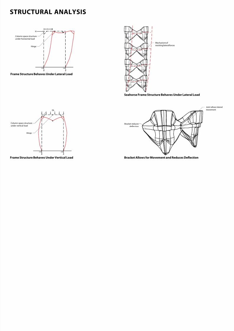
STRUCTURAL ANALYSIS
7/30/2019 121101 Kp Ppt Final
http://slidepdf.com/reader/full/121101-kp-ppt-final 74/122
Hinge
H
Column space structure
under horizontal load
DL
Hinge
Column space structure
under vertical load
Joint allows lateral
movement
Bracket reduces
deection
Mechanism of
resisting lateral forces
Frame Structure Behaves Under Lateral Load
Frame Structure Behaves Under Vertical Load
Seahorse Frame Structure Behaves Under Lateral Load
Bracket Allows or Movement and Reduces Deection
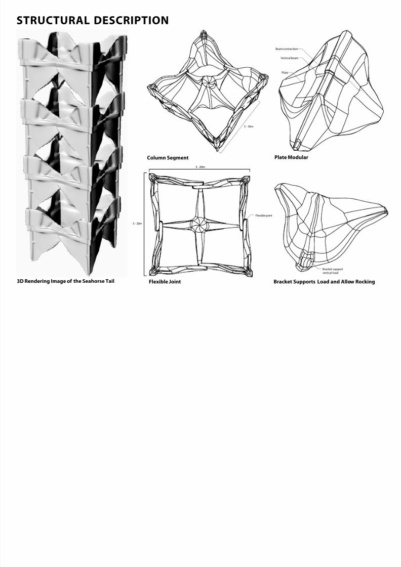
STRUCTURAL DESCRIPTION
7/30/2019 121101 Kp Ppt Final
http://slidepdf.com/reader/full/121101-kp-ppt-final 75/122
3 - 20m
3 - 20m
Beam connection
Vertical beam
Plate
Flexible joint
3 - 20m
Bracket support
vertical load
3D Rendering Image o the Seahorse Tail Flexible joint
Column Segment Plate Modular
Bracket Supports Load and Allow Rocking
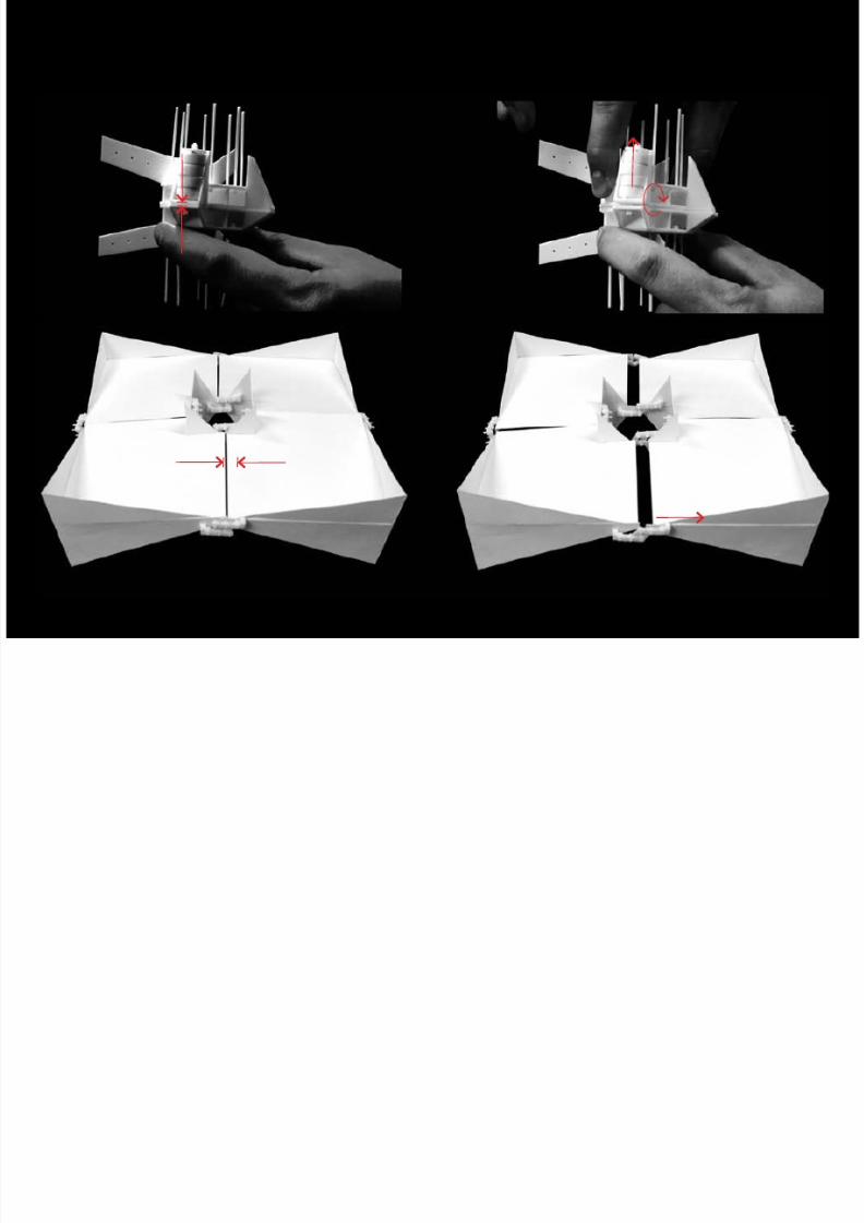
STRUCTURAL MOVEMENT
7/30/2019 121101 Kp Ppt Final
http://slidepdf.com/reader/full/121101-kp-ppt-final 76/122
Image o a Column Connection with Friction Spring Image o a Column Connection with Friction Spring Under Lateral Load
Image o the Seahorse Tail Structure at Center Image o the Seahorse Tail Structure Under Lateral Load
CASE STUDY
7/30/2019 121101 Kp Ppt Final
http://slidepdf.com/reader/full/121101-kp-ppt-final 77/122
CASE STUDY
7/30/2019 121101 Kp Ppt Final
http://slidepdf.com/reader/full/121101-kp-ppt-final 78/122
16m
Perspective View
CASE STUDY
7/30/2019 121101 Kp Ppt Final
http://slidepdf.com/reader/full/121101-kp-ppt-final 79/122
5
78
9
2
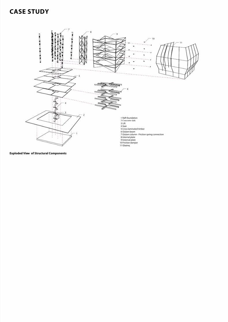
1 Raft foundation
2 Concrete slab
3 Lift
4 Stair
5 Cross laminated timber
6 Glulam beam
7 Glulam column - Friction spring connection
8 Internal plate
9 External plate
10 Friction damper
11 Glazing
4
1
3
6
10
11
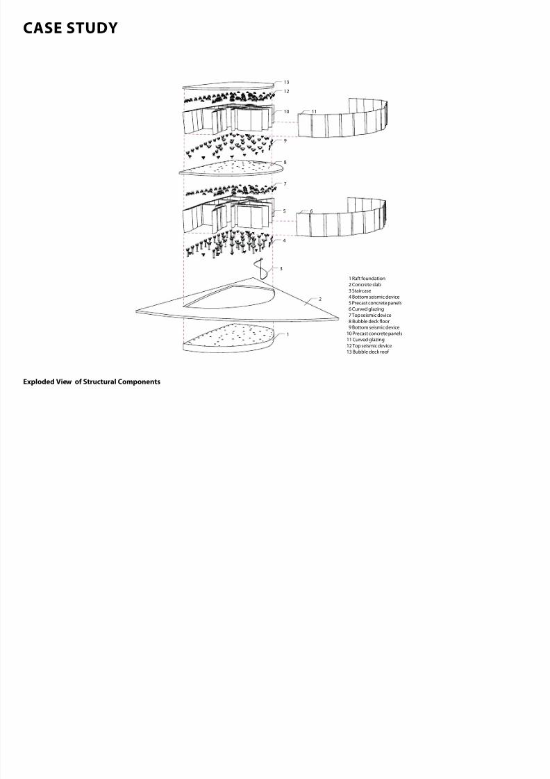
Exploded View o Structural Components
STRUCTURAL SETTING PRINCIPLES
7/30/2019 121101 Kp Ppt Final
http://slidepdf.com/reader/full/121101-kp-ppt-final 80/122
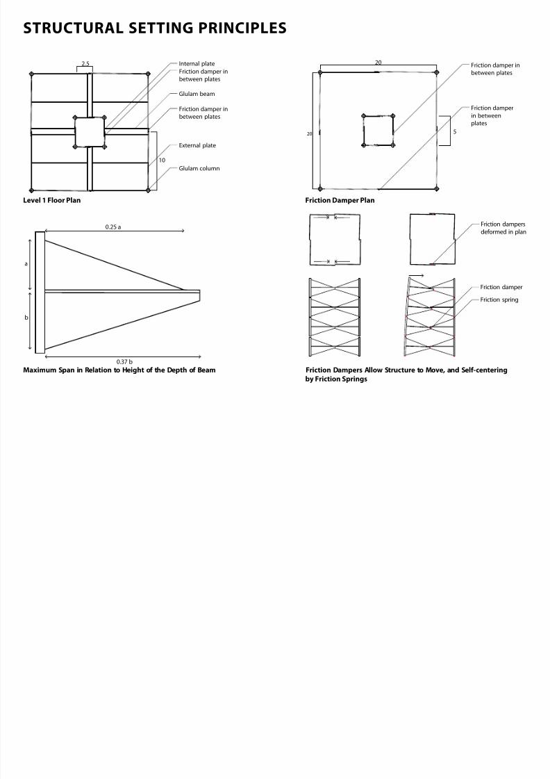
Glulam column
Glulam beam
10
2.5
External plate
Internal plate
Friction damper in
between plates
Friction damper in
between plates
20
20 Friction damper in
between plates
Friction damper
in between
plates
5
b
0.37 b
a
0.25 a
Friction spring
Friction damper
Friction dampers
deformed in plan
Friction Damper PlanLevel 1 Floor Plan
Maximum Span in Relation to Height o the Depth o Beam Friction Dampers Allow Structure to Move, and Selcenteringby Friction Springs
FLOOR CONNECTION AND FOUNDATION DETAIL
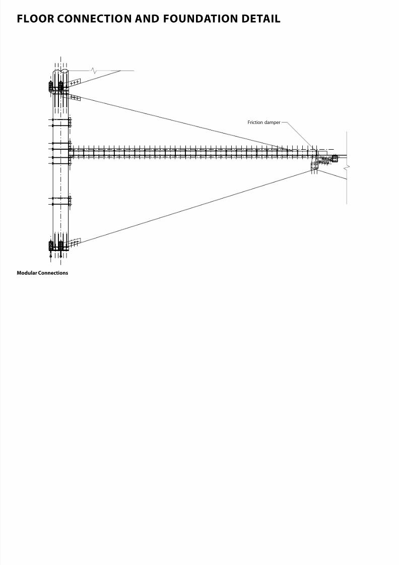
7/30/2019 121101 Kp Ppt Final
http://slidepdf.com/reader/full/121101-kp-ppt-final 81/122
Friction damper
Modular Connections
FLOOR CONNECTION AND FOUNDATION DETAIL
7/30/2019 121101 Kp Ppt Final
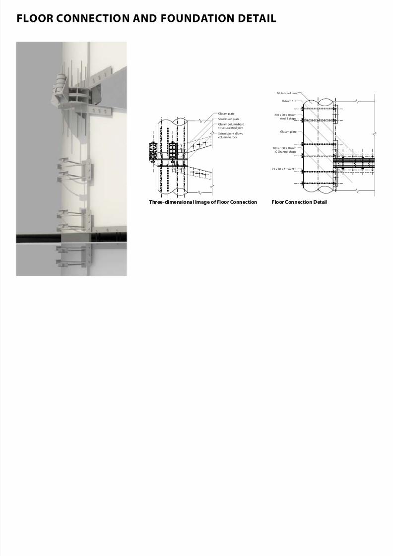
http://slidepdf.com/reader/full/121101-kp-ppt-final 82/122
Steel insert plate
Glulam column base
structural steel joint
Seismic joint allows
column to rock
Glulam plate
Glulam column
75 x 40 x 7 mm PFC
Glulam plate
169mm CLT
200 x 90 x 10 mm
steel T shape
100 x 100 x 10 mm
C Channel shape
Threedimensional Image o Floor Connection Floor Connection Detail
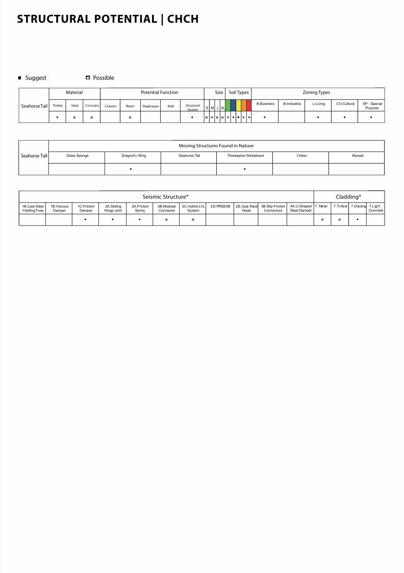
STRUCTURAL POTENTIAL | CHCH
7/30/2019 121101 Kp Ppt Final
http://slidepdf.com/reader/full/121101-kp-ppt-final 83/122
Suggest Possible
Seahorse Tail Glass Sponge Dragonfly Wing ChitonSeahorse Tail Threespine Stickleback Mussel
Moving Structures Found in Nature
Material
Timber Steel Concrete
Soil Types Zoning Types
B-Business B-Industrial SP - Special
Purpose
L-Living CU-Cultural
Potential Function Size
S M L XLColumn Beam WallDiaphargm Structural
SystemSeahorse Tail
Seismic Structure* Cladding*
1B.Cast SteelYielding Fuse
1B.ViscousDamper
2A.FrictionSpring
1C.FrictionDamper
2A.SlidingHinge Joint
2B.Modular Connector
2C.Hybrid LVLSystem
2D.PRESSS 2E.Cast SteelNode
3B.Slip-Friction
Connectors
4A.U-Shaped
Steel Damper
7 . Meta l 7 .Timber 7.Glazing 7.L ight
Concrete

7/30/2019 121101 Kp Ppt Final
http://slidepdf.com/reader/full/121101-kp-ppt-final 84/122
THREESPINE STICKLEBACK
THREESPINE STICKLEBACK FISH
7/30/2019 121101 Kp Ppt Final
http://slidepdf.com/reader/full/121101-kp-ppt-final 85/122
Image o Threespine Stickleback (from Song, 2010)
MicroCT Scan o Lateral Plates
(from Song, 2010)
SEM Images o A Socket Let and a Bony Protrusion Right(from Song, 2010)
Threedimensional Microimage o a Bony Protrusion, Facing Its Mating Socket(from Song, 2010)
STRUCTURAL ANALYSIS
7/30/2019 121101 Kp Ppt Final
http://slidepdf.com/reader/full/121101-kp-ppt-final 86/122
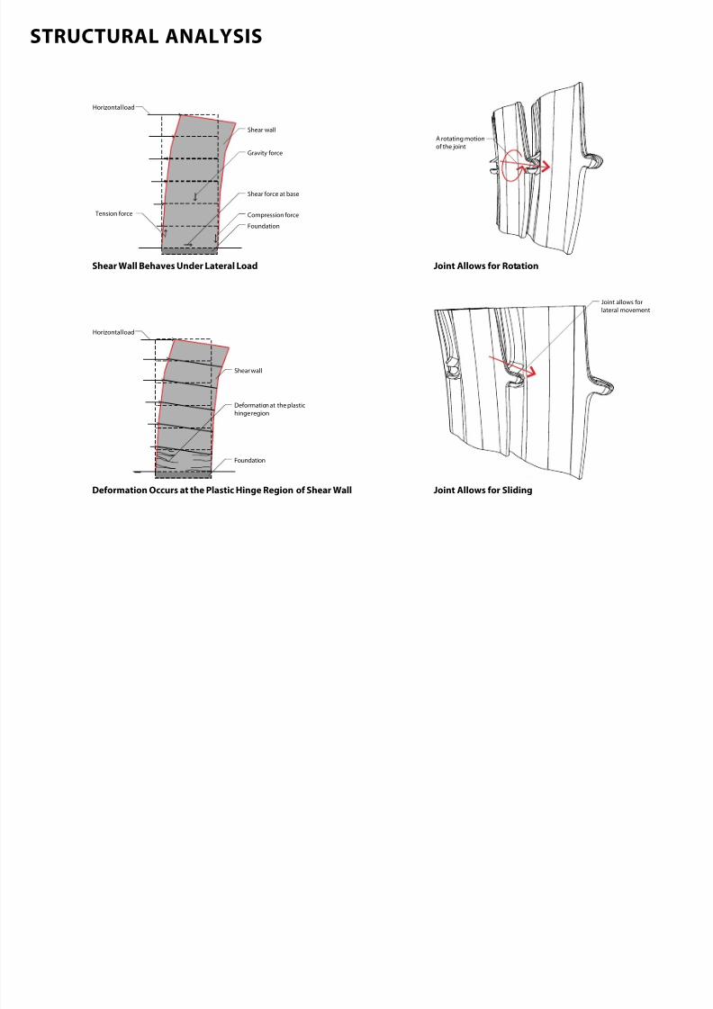
Deformation at the plastic
hinge region
Foundation
Shear wall
Horizontal load
A rotating motionof the joint
Joint allows for
lateral movement
Horizontal load
Tension force
Shear wall
Gravity force
Compression force
Shear force at base
Foundation
Shear Wall Behaves Under Lateral Load
Deormation Occurs at the Plastic Hinge Region o Shear Wall
joint Allows or Rotation
joint Allows or Sliding
STRUCTURAL DESCRIPTION
7/30/2019 121101 Kp Ppt Final
http://slidepdf.com/reader/full/121101-kp-ppt-final 87/122
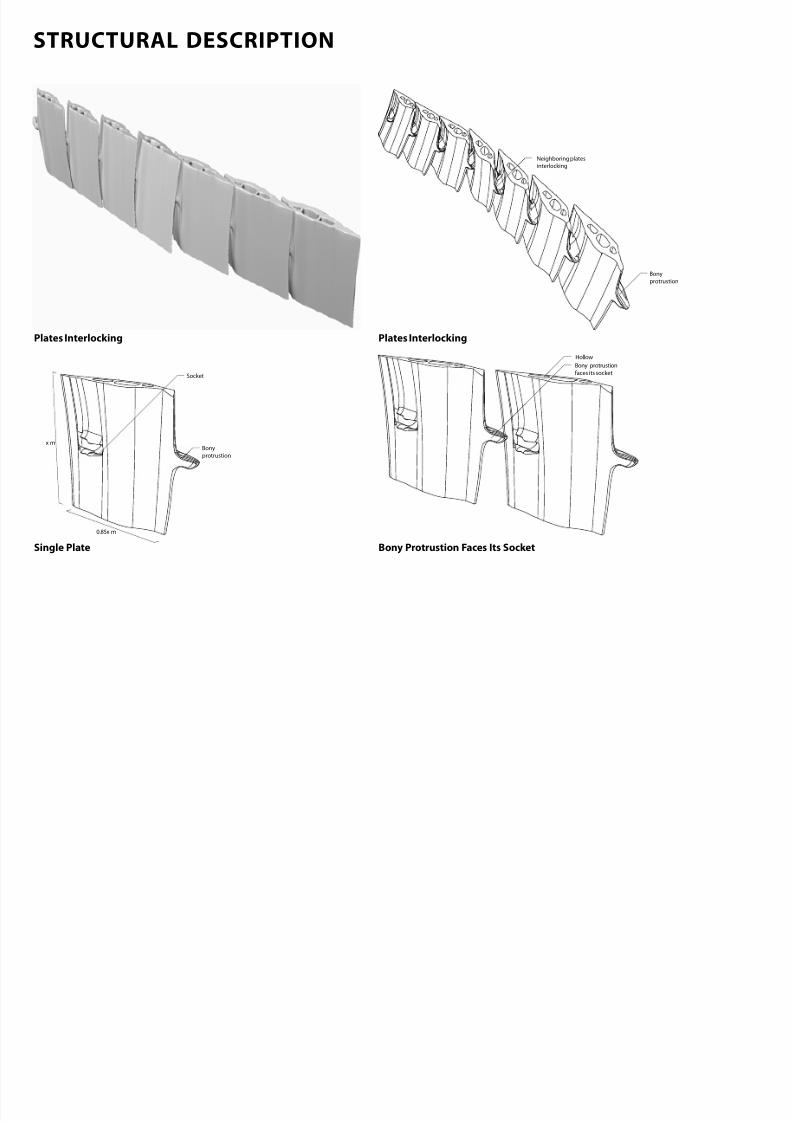
Neighboring plates
interlocking
Bony
protrustion
Bony
protrustion
Socket
Bony protrustion
faces its socket
Hollow
x m
0.85x m
Plates Interlocking
Single Plate Bony Protrustion Faces Its Socket
Plates Interlocking
STRUCTURAL MOVEMENT
7/30/2019 121101 Kp Ppt Final
http://slidepdf.com/reader/full/121101-kp-ppt-final 88/122
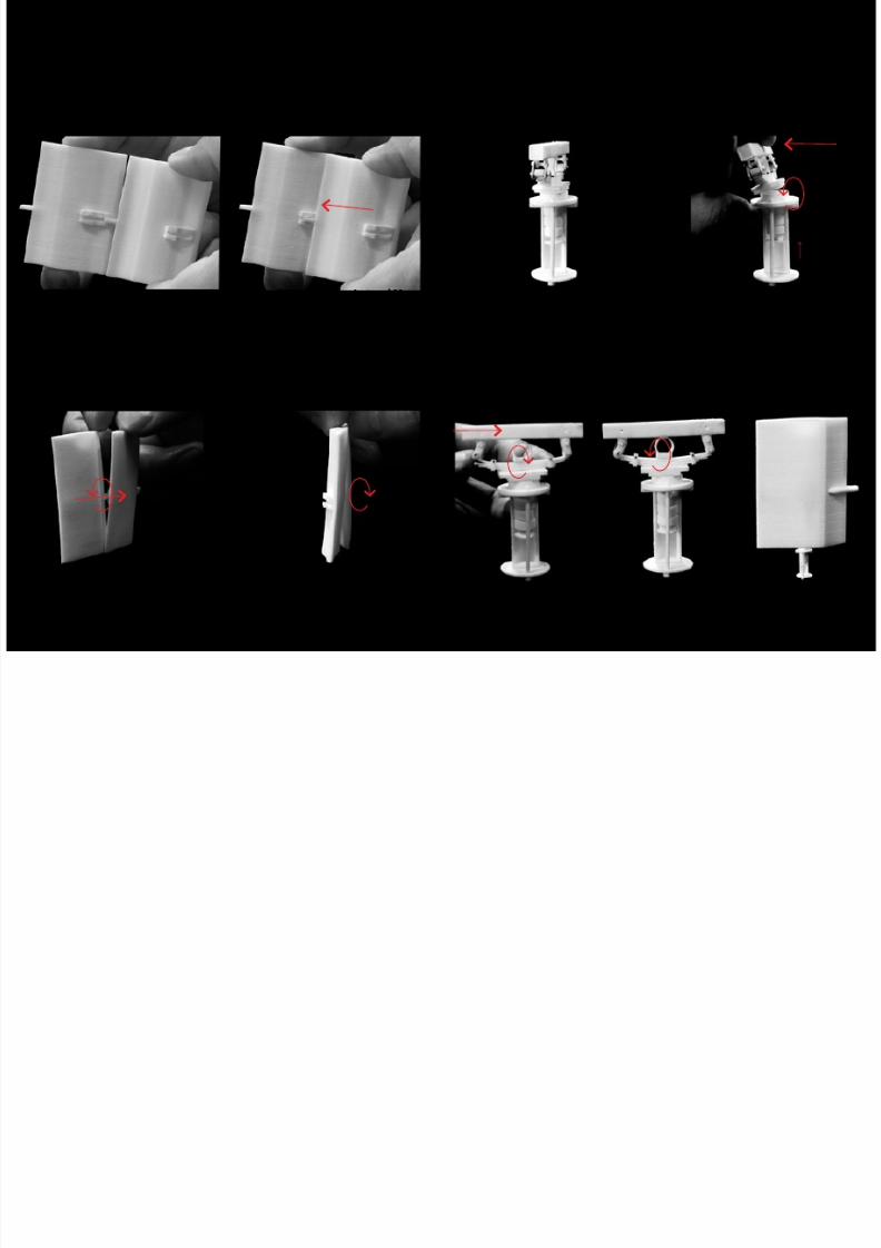
Image o Plates’s joint
Image o a Plate Rotates Counterclockwise
Image o Plates Under Lateral Movement
Plate Rotates Clockwise
Image o a Seismic Device Seismic Device Under Lateral Movement
Lea Spring Under Lateral Movement and Recentre Itsel
CASE STUDY
7/30/2019 121101 Kp Ppt Final
http://slidepdf.com/reader/full/121101-kp-ppt-final 89/122
CASE STUDY
7/30/2019 121101 Kp Ppt Final
http://slidepdf.com/reader/full/121101-kp-ppt-final 90/122
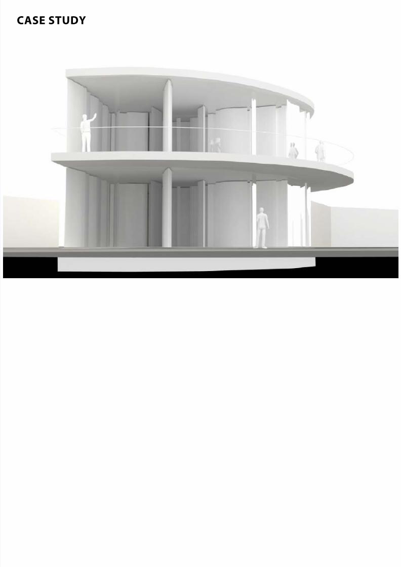
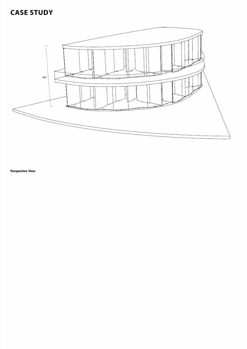
8m
Perspective View
CASE STUDY
7/30/2019 121101 Kp Ppt Final
http://slidepdf.com/reader/full/121101-kp-ppt-final 91/122
1
2
3
4
5 6
7
8
9
1110
12
13
1 Raft foundation
2 Concrete slab
3 Staircase
4 Bottom seismic device5 Precast concrete panels
6 Curved glazing
7 Top seismic device
8 Bubble deck oor
9 Bottom seismic device
10 Precast concrete panels
11 Curved glazing
12 Top seismic device
13 Bubble deck roof
Exploded View o Structural Components
STRUCTURAL SETTING PRINCIPLES
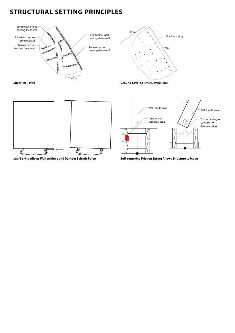
7/30/2019 121101 Kp Ppt Final
http://slidepdf.com/reader/full/121101-kp-ppt-final 92/122
Longitudinal load
bearing shear-wall
Transverse load
bearing shear-wall
6.2m
2.5 x 0.4m precast
concrete wall
Transverse loadbearing shear-wall
Longitudinal load
bearing shear-wall
22m
12m
Friction spring
Tension and
compress area
Bolt in tension
Friction spring in
compression
Wall (not to scale)Wall (not to scale)
Shearwall Plan Ground Level Seismic Device Plan
Selcentering Friction Spring Allows Structure to MoveLea Spring Allows Wall to Move and Damper Seismic Force
FLOOR CONNECTION AND FOUNDATION DETAIL
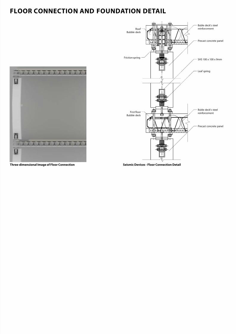
7/30/2019 121101 Kp Ppt Final
http://slidepdf.com/reader/full/121101-kp-ppt-final 93/122
Buble deck’s steel
reinforcementRoof
Bubble deck
Buble deck’s steel
reinforcement
SHS 100 x 100 x 9mm
Precast concrete panel
Leaf spring
First oor
Bubble deck
Precast concrete panel
Friction spring
Seismic Devices Floor Connection DetailThreedimensional Image o Floor Connection
FLOOR CONNECTION AND FOUNDATION DETAIL
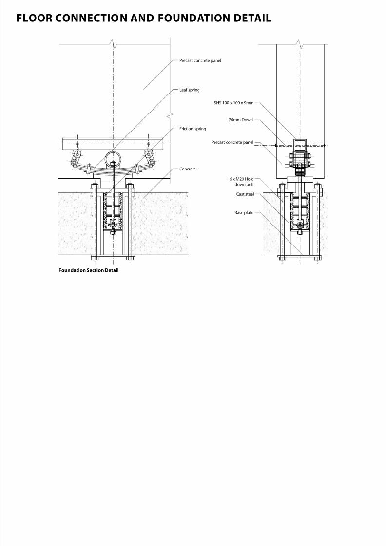
7/30/2019 121101 Kp Ppt Final
http://slidepdf.com/reader/full/121101-kp-ppt-final 94/122
6 x M20 Hold
down bolt
Base plate
Cast steel
SHS 100 x 100 x 9mm
20mm Dowel
Leaf spring
Friction spring
Precast concrete panel
Concrete
Precast concrete panel
Foundation Section Detail
STRUCTURAL POTENTIAL | CHCH
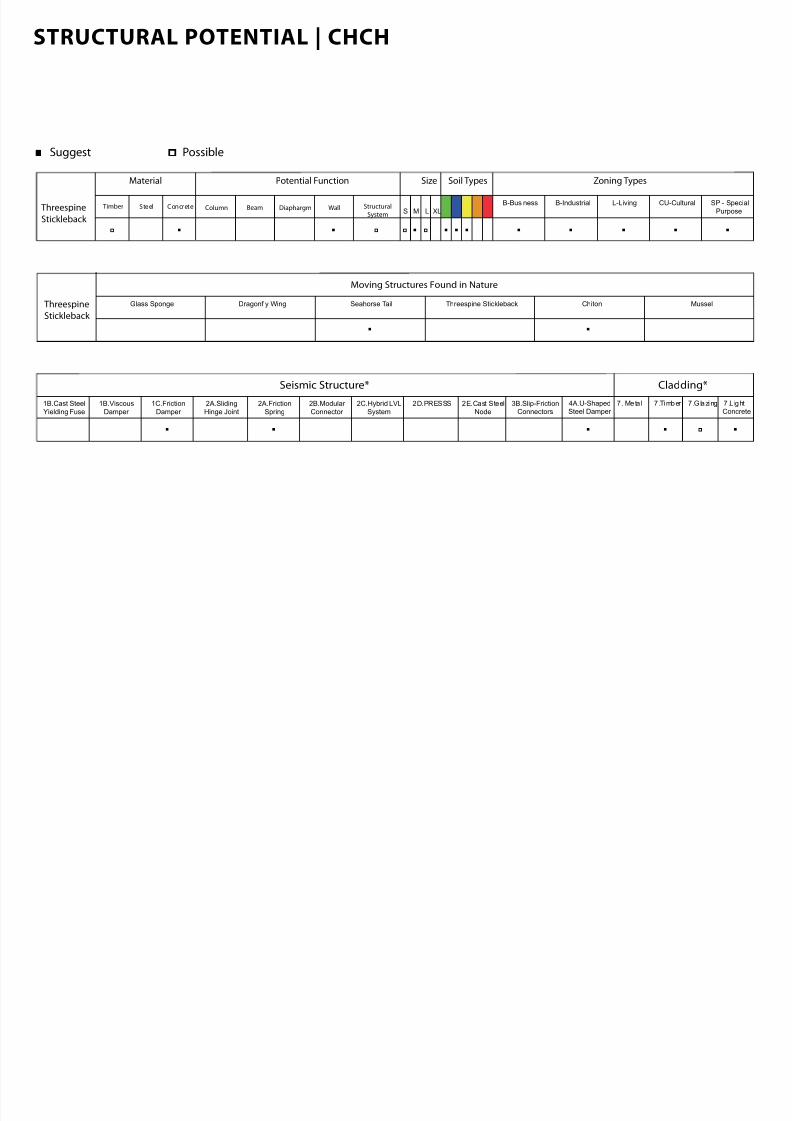
7/30/2019 121101 Kp Ppt Final
http://slidepdf.com/reader/full/121101-kp-ppt-final 95/122
Suggest Possible
Material
Timber Steel Concrete
Soil Types Zoning Types
B-Business B-Industrial SP - Special
Purpose
L-Living CU-Cultural
Potential Function Size
S M L XLColumn Beam WallDiaphargm Structural
System Threespine
Stickleback
Seismic Structure* Cladding*
1B.Cast Steel
Yielding Fuse
1B.Viscous
Damper
2A.Friction
Spring
1C.Friction
Damper
2A.Sliding
Hinge Joint
2B.Modular
Connector
2C.Hybrid LVL
System
2D.PRESSS 2E.Cast Steel
Node
3B.Slip-FrictionConnectors
4A.U-ShapedSteel Damper
7 . Meta l 7 .Timber 7.Glazing 7.L ightConcrete
Threespine
Stickleback
Glass Sponge Dragonfly Wing ChitonSeahorse Tail Threespine Stickleback Mussel
Moving Structures Found in Nature

7/30/2019 121101 Kp Ppt Final
http://slidepdf.com/reader/full/121101-kp-ppt-final 96/122
CHITON
CHITON SHELL
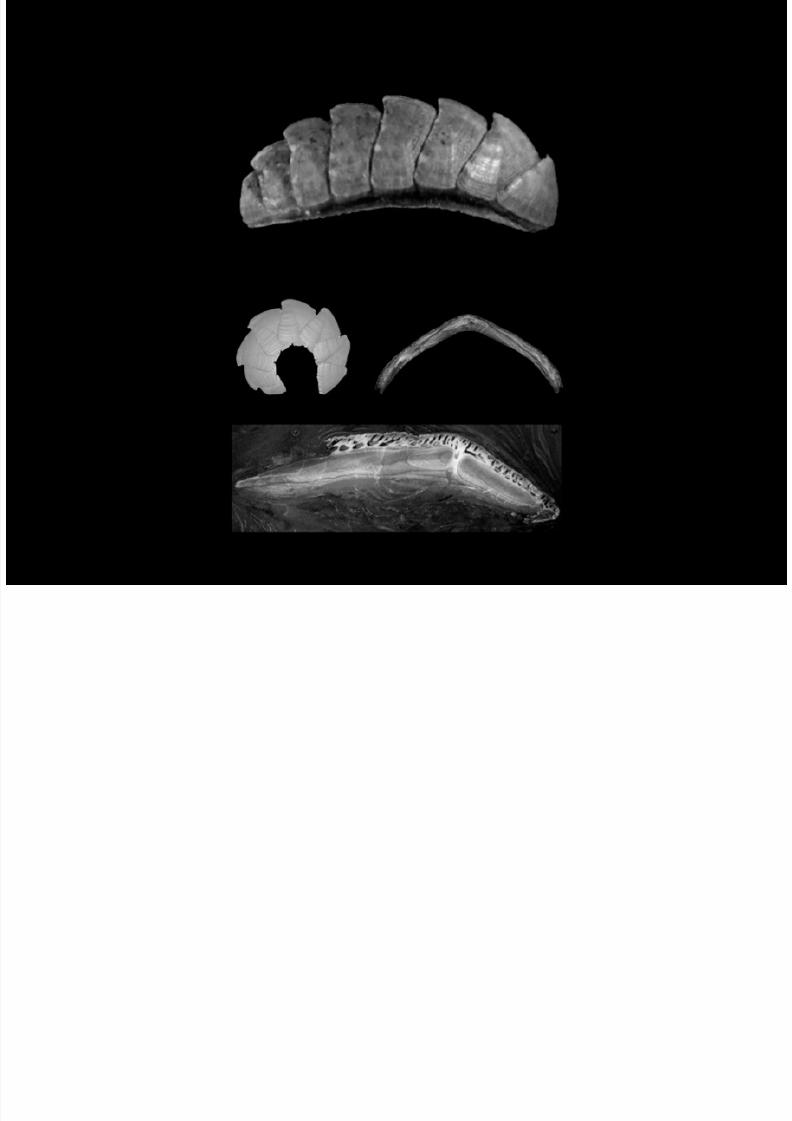
7/30/2019 121101 Kp Ppt Final
http://slidepdf.com/reader/full/121101-kp-ppt-final 97/122
Microscopy Image o a Dried Shell(from Connors, 2012)
Chiton in a Deensive(from Connors, 2012)
Image o Longitudinal CrossSection o a Shell(from Connors, 2012)
Transverse CrossSection(from Connors, 2012)
STRUCTURAL ANALYSIS
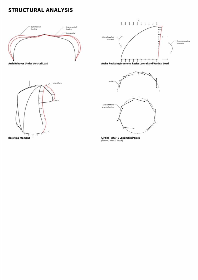
7/30/2019 121101 Kp Ppt Final
http://slidepdf.com/reader/full/121101-kp-ppt-final 98/122
Asymmetrical
loading
Symmetrical
loading
Arch prole
Lateral force
External applied
momentInternal resisting
moment
DL
Plate
Circles t to 16
landmark points
Arch Behaves Under Vertical Load Arch’s Resisting Moments Resist Lateral and Vertical Load
Circles Fit to 16 Landmark Points
(from Connors, 2012)
Resisting Moment
STRUCTURAL DESCRIPTION
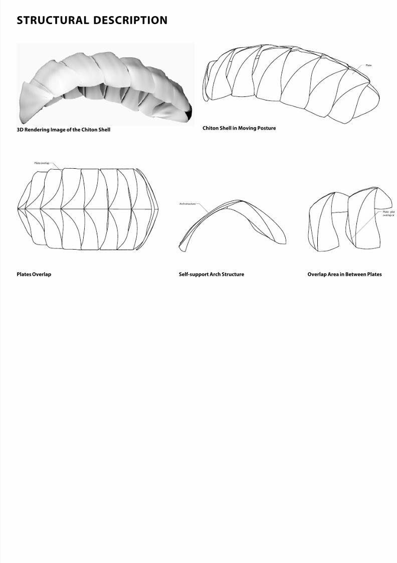
7/30/2019 121101 Kp Ppt Final
http://slidepdf.com/reader/full/121101-kp-ppt-final 99/122
Plate
Plate overlap
Arch structure
Plate - plat
overlap ar
Plates Overlap Selsupport Arch Structure Overlap Area in Between Plates
Chiton Shell in Moving Posture3D Rendering Image o the Chiton Shell
STRUCTURAL MOVEMENT
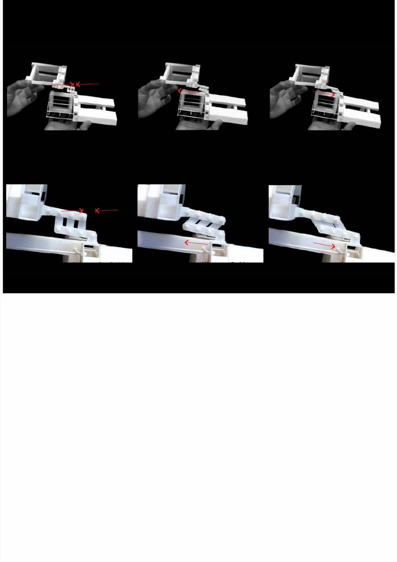
7/30/2019 121101 Kp Ppt Final
http://slidepdf.com/reader/full/121101-kp-ppt-final 100/122
Zoom in Image o a Friction Damper at Rest Position
Image o a Cantilever Truss Connection Cantilever Truss Connection in Forward Movement
Friction Damper in Forward Movement Position
Cantilever Truss Connection in Reverse Movement
Friction Damper in Reverse Movement Position
CASE STUDY
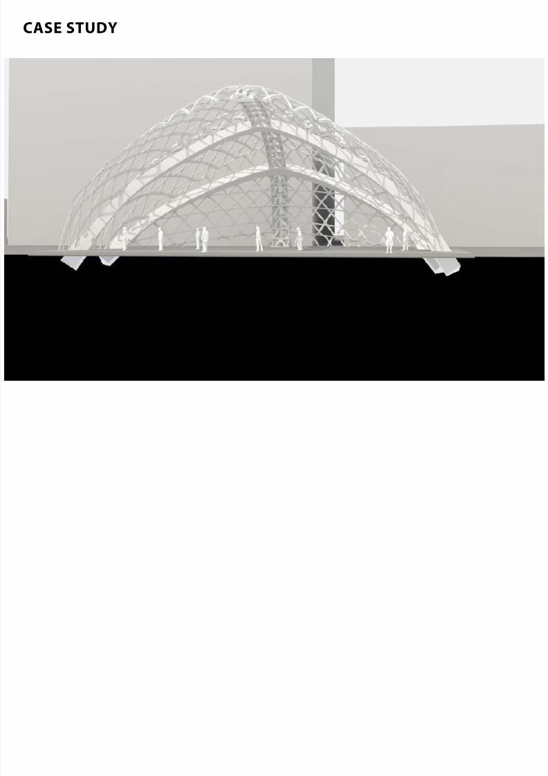
7/30/2019 121101 Kp Ppt Final
http://slidepdf.com/reader/full/121101-kp-ppt-final 101/122
CASE STUDY
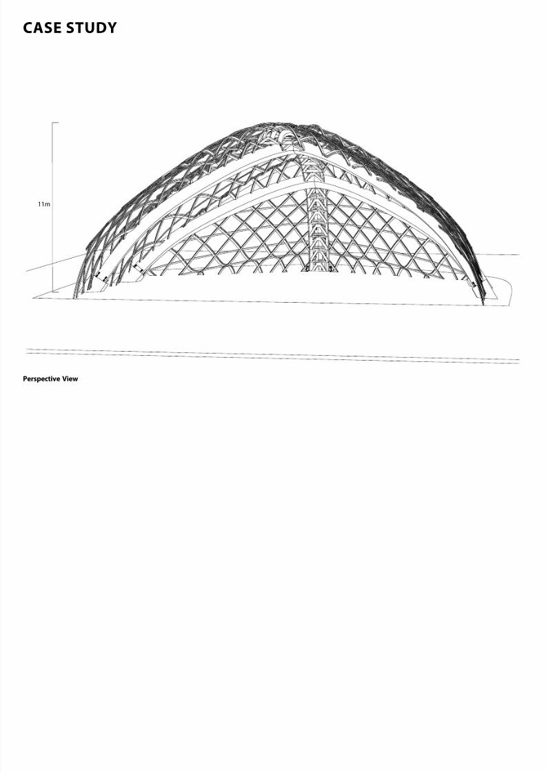
7/30/2019 121101 Kp Ppt Final
http://slidepdf.com/reader/full/121101-kp-ppt-final 102/122
11m
Perspective View
CASE STUDY
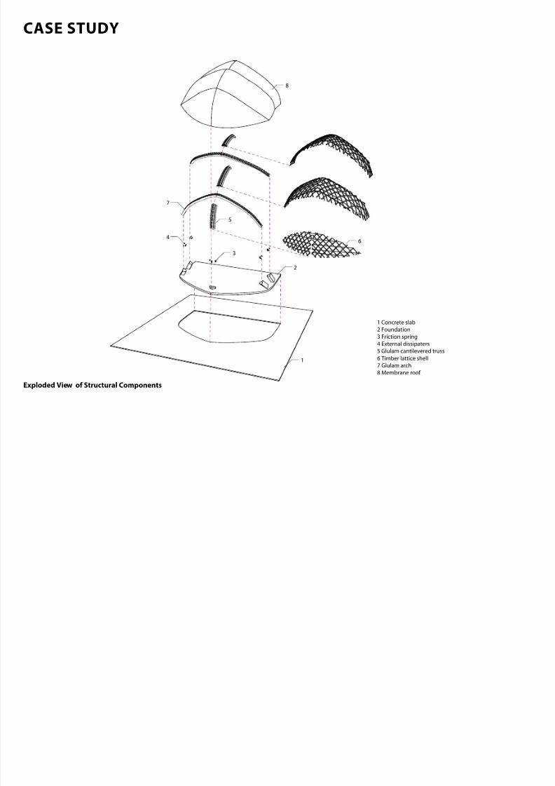
7/30/2019 121101 Kp Ppt Final
http://slidepdf.com/reader/full/121101-kp-ppt-final 103/122
1
2
3
4
5
6
8
1 Concrete slab
2 Foundation
3 Friction spring
4 External dissipaters
5 Glulam cantilevered truss
6 Timber lattice shell
7 Glulam arch
8 Membrane roof
7
Exploded View o Structural Components
STRUCTURAL SETTING PRINCIPLES
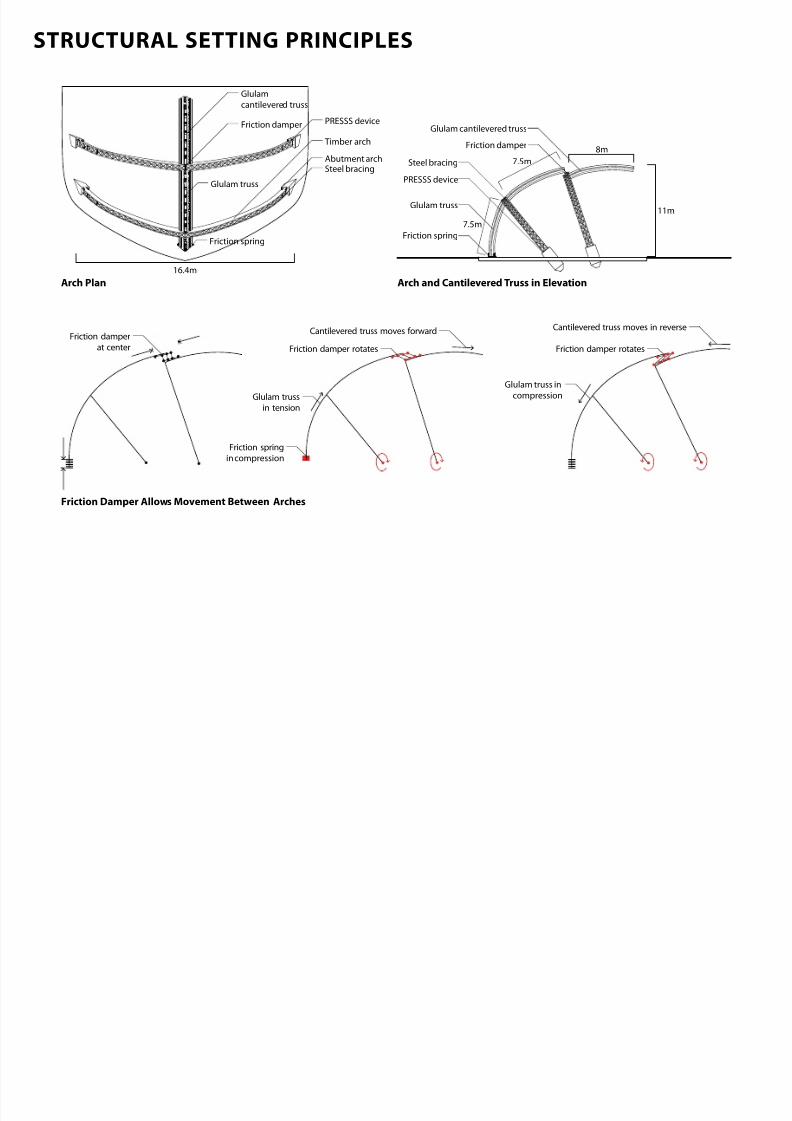
7/30/2019 121101 Kp Ppt Final
http://slidepdf.com/reader/full/121101-kp-ppt-final 104/122
8m
7.5m
7.5m
Friction spring
Glulam truss
Friction damper
Glulam cantilevered truss
11m
Steel bracing
PRESSS device
Friction spring
PRESSS device
Abutment archSteel bracing
Timber arch
Friction damper
Glulam
cantilevered truss
Glulam truss
16.4m
Glulam truss
in tension
Cantilevered truss moves forward
Friction damper rotates
Friction spring
in compression
Glulam truss in
compression
Cantilevered truss moves in reverse
Friction damper rotates
Friction damper
at center
Arch Plan Arch and Cantilevered Truss in Elevation
Friction Damper Allows Movement Between Arches
FLOOR CONNECTION AND FOUNDATION DETAIL
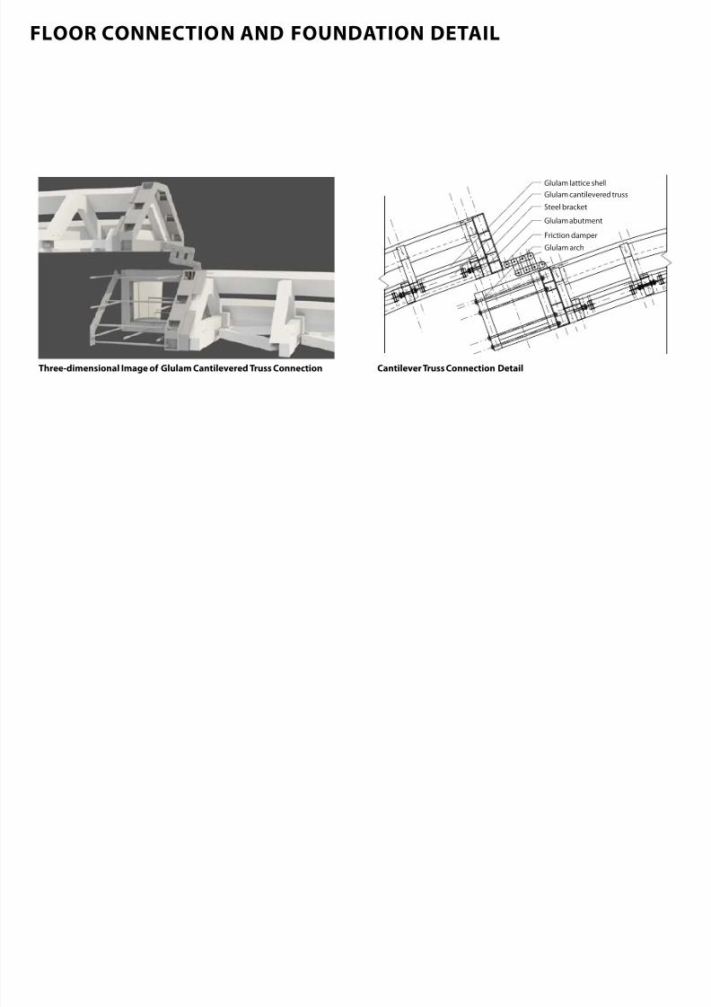
7/30/2019 121101 Kp Ppt Final
http://slidepdf.com/reader/full/121101-kp-ppt-final 105/122
Friction damper
Steel bracket
Glulam lattice shell
Glulam abutment
Glulam cantilevered truss
Glulam arch
Cantilever Truss Connection DetailThreedimensional Image o Glulam Cantilevered Truss Connection
FLOOR CONNECTION AND FOUNDATION DETAIL
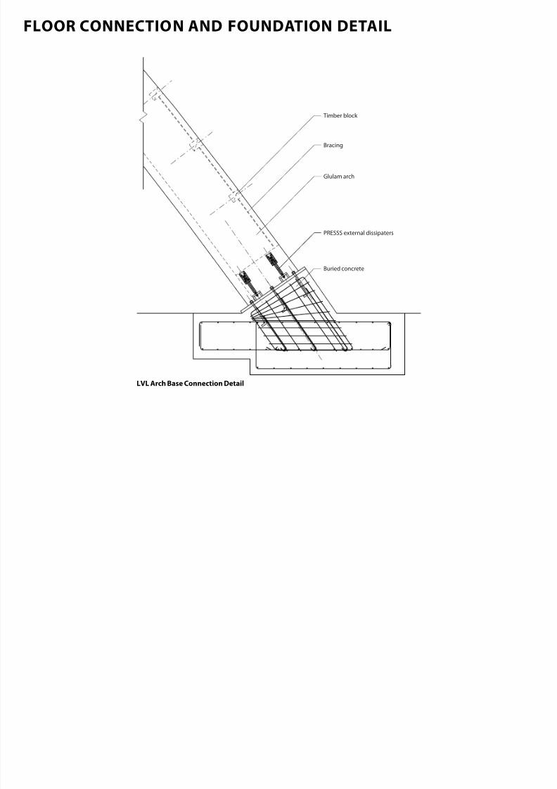
7/30/2019 121101 Kp Ppt Final
http://slidepdf.com/reader/full/121101-kp-ppt-final 106/122
PRESSS external dissipaters
Glulam arch
Timber block
Bracing
Buried concrete
LVL Arch Base Connection Detail
STRUCTURAL POTENTIAL | CHCH
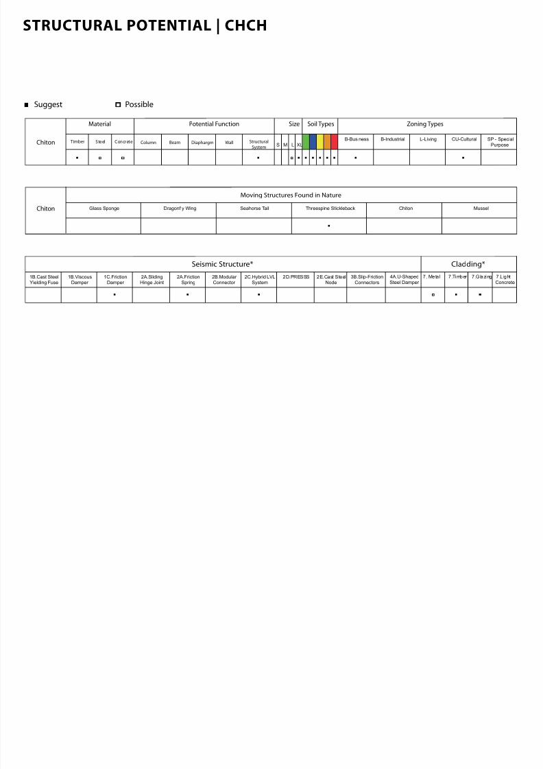
7/30/2019 121101 Kp Ppt Final
http://slidepdf.com/reader/full/121101-kp-ppt-final 107/122
Suggest Possible
Material
Timber Steel Concrete
Soil Types Zoning Types
B-Business B-Industrial SP - Special
Purpose
L-Living CU-Cultural
Potential Function Size
S M L XLColumn Beam WallDiaphargm Structural
SystemChiton
Seismic Structure* Cladding*
1B.Cast SteelYielding Fuse
1B.ViscousDamper
2A.FrictionSpring
1C.FrictionDamper
2A.SlidingHinge Joint
2B.Modular Connector
2C.Hybrid LVLSystem
2D.PRESSS 2E.Cast SteelNode
3B.Slip-Friction
Connectors
4A.U-Shaped
Steel Damper
7 . Meta l 7 .Timber 7.Glazing 7.L ight
Concrete
Chiton Glass Sponge Dragonfly Wing ChitonSeahorse Tail Threespine Stickleback Mussel
Moving Structures Found in Nature

7/30/2019 121101 Kp Ppt Final
http://slidepdf.com/reader/full/121101-kp-ppt-final 108/122
MUSSEL
THE MUSSEL BYSSUS THREADS
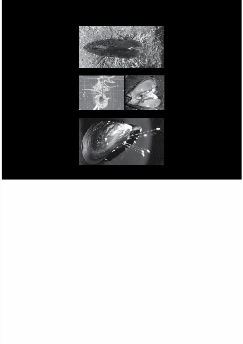
7/30/2019 121101 Kp Ppt Final
http://slidepdf.com/reader/full/121101-kp-ppt-final 109/122
Image o Byssal Threads(from Zinkova, 2012)
The Byssus Threads(from Messersmith, 2012)
Internal Anatomy Shows Byssal Threads(from Estudillo, 2012)
Photograph o Distal Region(from Moeser, 1996)
STRUCTURAL ANALYSIS
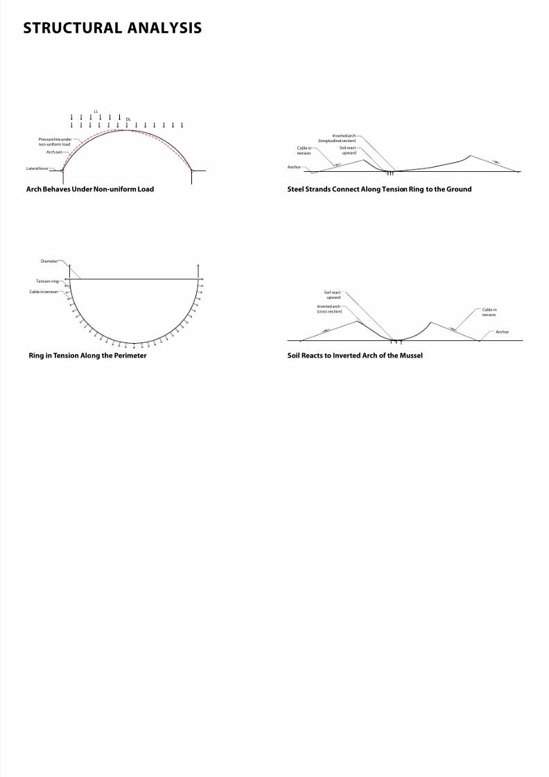
7/30/2019 121101 Kp Ppt Final
http://slidepdf.com/reader/full/121101-kp-ppt-final 110/122
Lateral force
Arch axis
LL
DL
Pressure line under
non-uniform load
Tension ring
Diameter
Cable in tension
Cable in
tension
Inverted arch
(longitudinal section)
Anchor
Soil react
upward
Cable in
tension
Anchor
Soil react
upward
Inverted arch
(cross section)
Arch Behaves Under Nonuniorm Load
Ring in Tension Along the Perimeter Soil Reacts to Inverted Arch o the Mussel
Steel Strands Connect Along Tension Ring to the Ground
STRUCTURAL DESCRIPTION
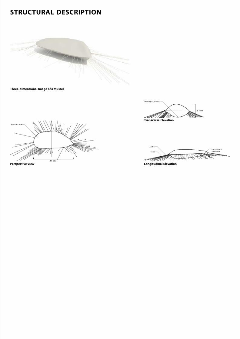
7/30/2019 121101 Kp Ppt Final
http://slidepdf.com/reader/full/121101-kp-ppt-final 111/122
Rocking foundation
Shell structure
40 - 92m
15 - 60m
Anchor
Inverted arch
foundationCable
Threedimensional Image o a Mussel
Perspective View Longitudinal Elevation
Transverse Elevation
STRUCTURAL MOVEMENT
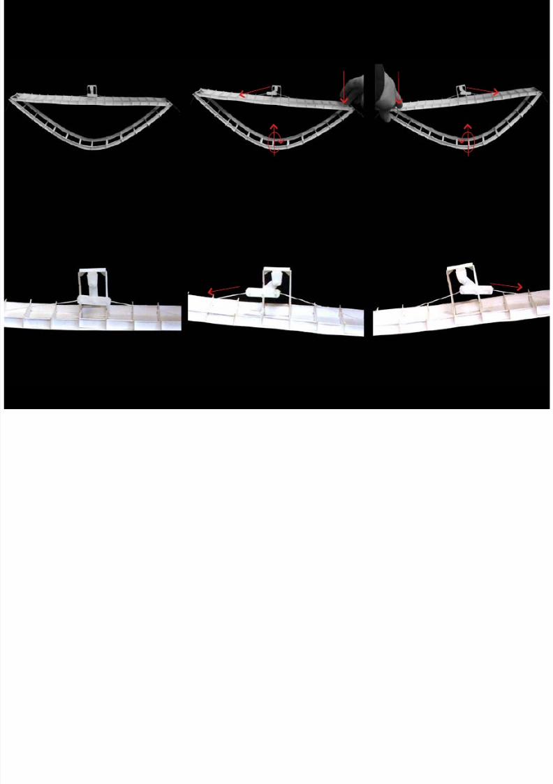
7/30/2019 121101 Kp Ppt Final
http://slidepdf.com/reader/full/121101-kp-ppt-final 112/122
Zoom in Image o a Mussel Section in Rest Position
Image o a Mussel Section Mussel Section in Forward Movement Position
Mussel Section in Forward Movement Position
Mussel Section in Reverse Movement Position
Mussel Section in Reverse Movement Position
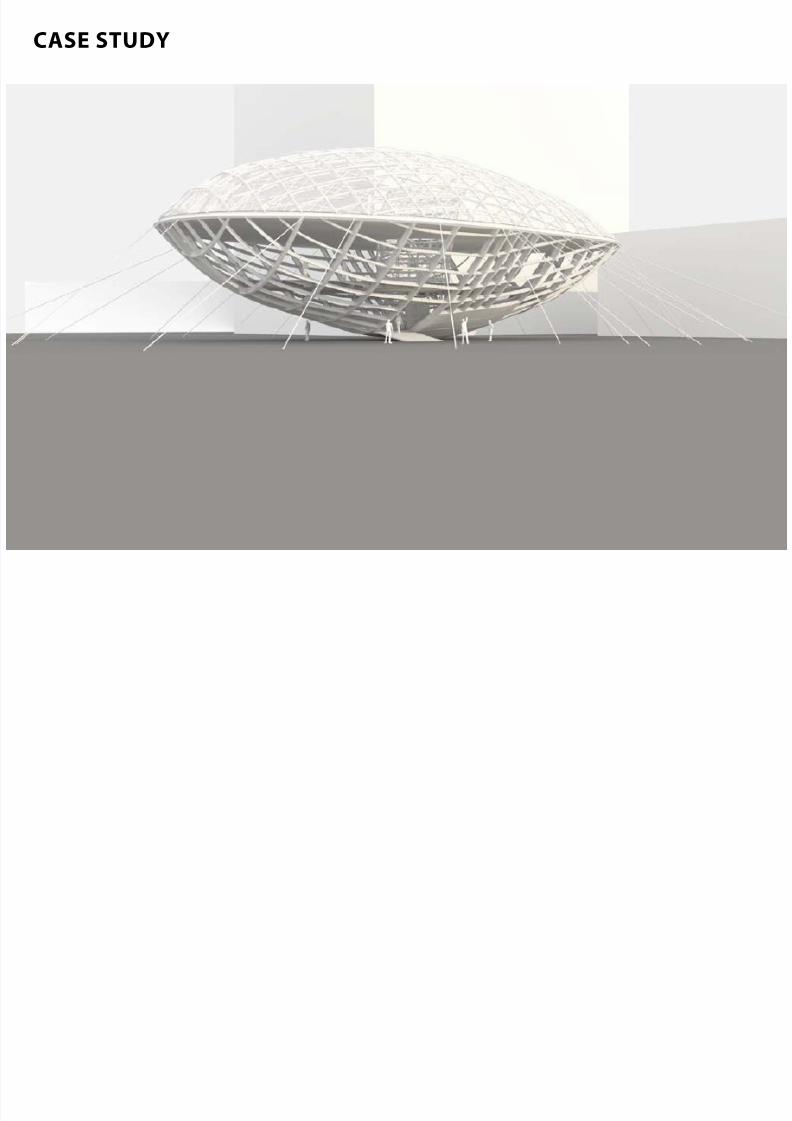
7/30/2019 121101 Kp Ppt Final
http://slidepdf.com/reader/full/121101-kp-ppt-final 113/122
CASE STUDY
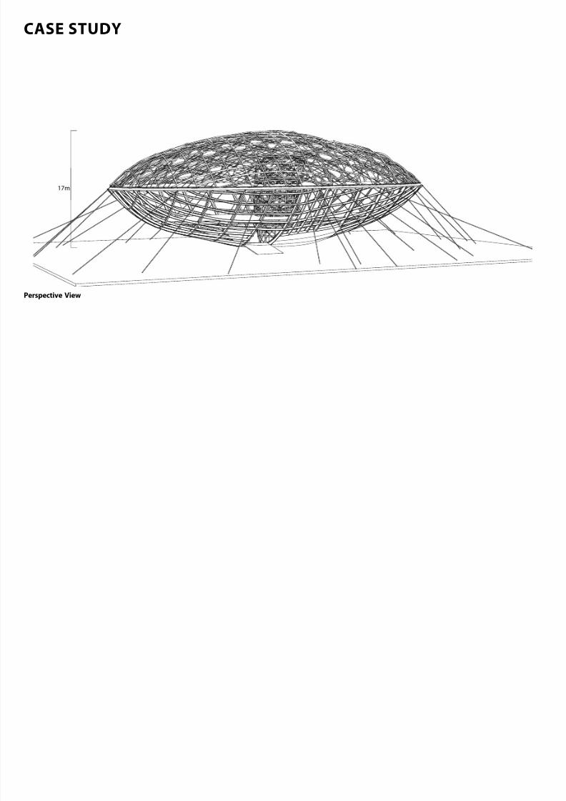
7/30/2019 121101 Kp Ppt Final
http://slidepdf.com/reader/full/121101-kp-ppt-final 114/122
17m
Perspective View
CASE STUDY
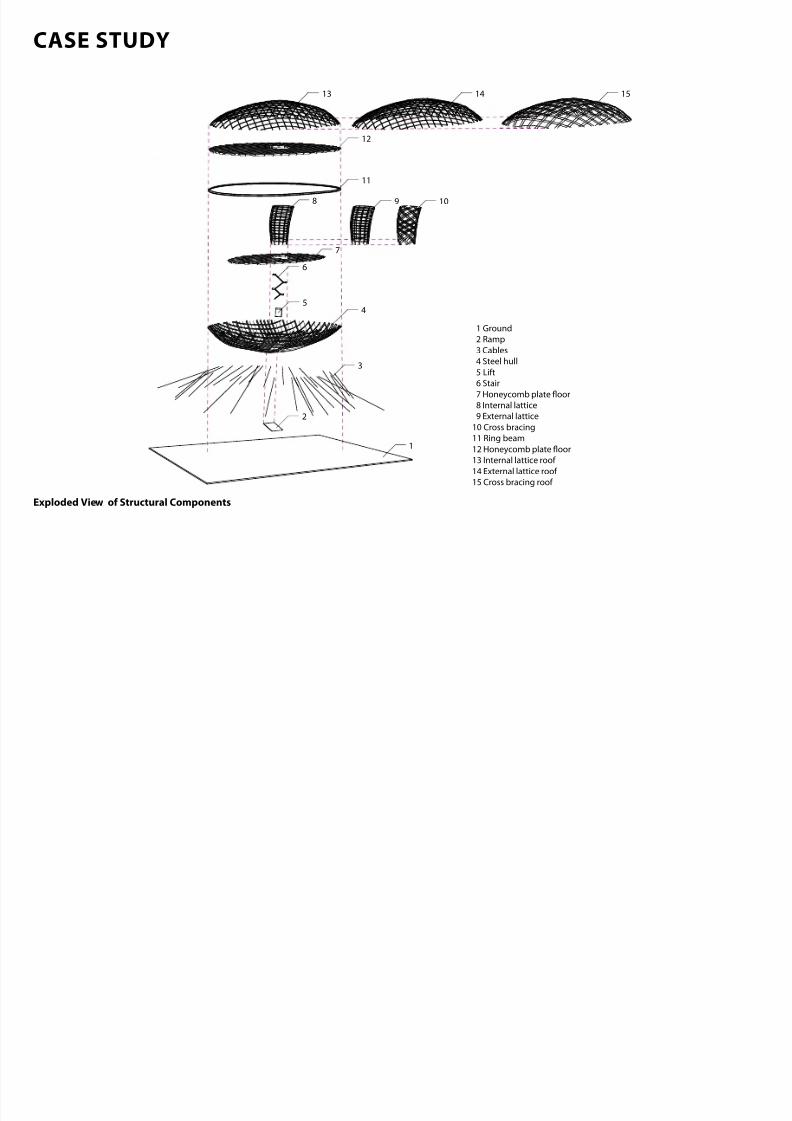
7/30/2019 121101 Kp Ppt Final
http://slidepdf.com/reader/full/121101-kp-ppt-final 115/122
1 Ground
2 Ramp
3 Cables
4 Steel hull
5 Lift
6 Stair
7 Honeycomb plate oor
8 Internal lattice
9 External lattice
10 Cross bracing11 Ring beam
12 Honeycomb plate oor
13 Internal lattice roof
14 External lattice roof
15 Cross bracing roof
12
14 1513
11
8 9 10
5
6
7
2
4
1
3
Exploded View o Structural Components
STRUCTURAL SETTING PRINCIPLES
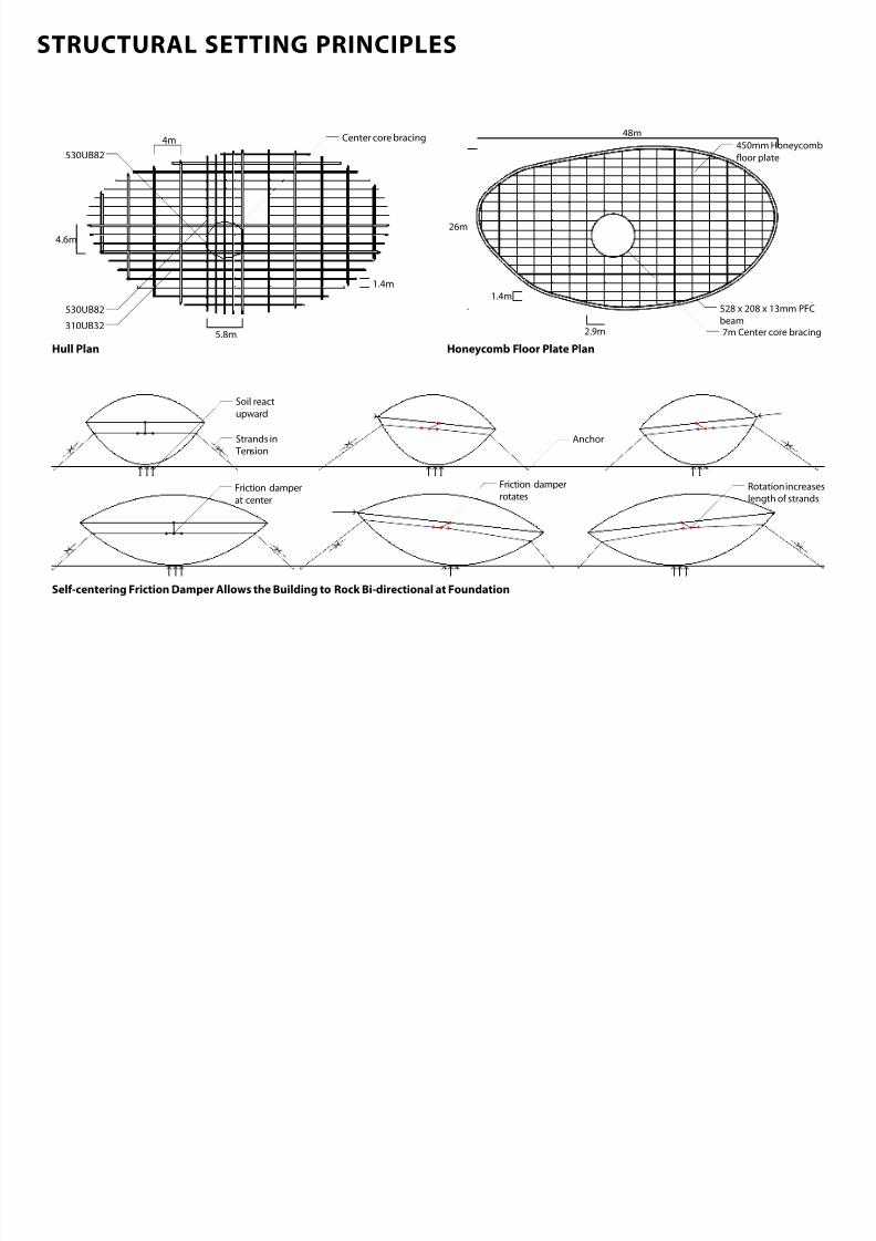
7/30/2019 121101 Kp Ppt Final
http://slidepdf.com/reader/full/121101-kp-ppt-final 116/122
4.6m
4m
1.4m
5.8m
Center core bracing
530UB82
310UB32
530UB82
26m
48m
7m Center core bracing
528 x 208 x 13mm PFC
beam
450mm Honeycomb
oor plate
2.9m
1.4m
Rotation increases
length of strands
Friction damper
rotates
Strands in
Tension
Soil react
upward
Friction damper
at center
Anchor
Hull Plan Honeycomb Floor Plate Plan
Selcentering Friction Damper Allows the Building to Rock Bidirectional at Foundation
FLOOR CONNECTION AND FOUNDATION DETAIL
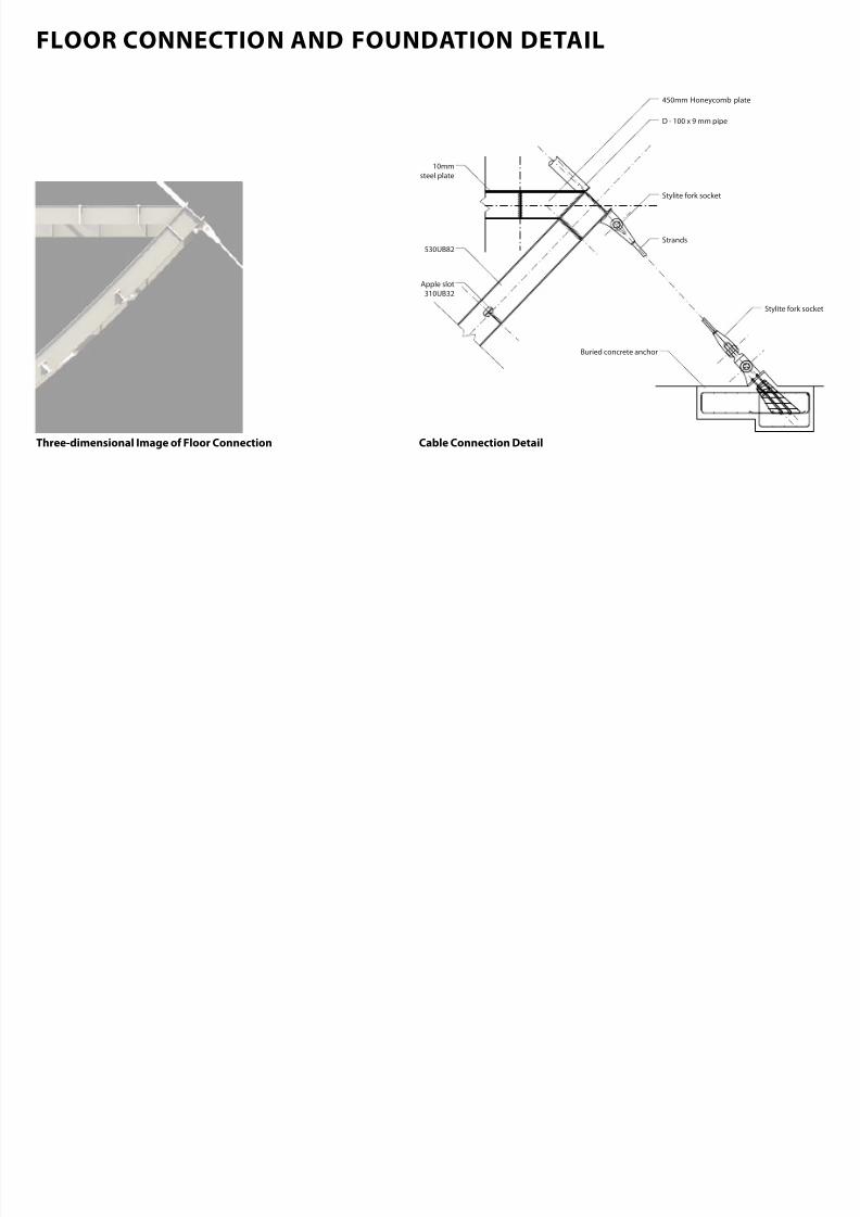
7/30/2019 121101 Kp Ppt Final
http://slidepdf.com/reader/full/121101-kp-ppt-final 117/122
530UB82
Strands
D - 100 x 9 mm pipe
10mmsteel plate
Apple slot
310UB32
450mm Honeycomb plate
Stylite fork socket
Stylite fork socket
Buried concrete anchor
Cable Connection DetailThreedimensional Image o Floor Connection
FLOOR CONNECTION AND FOUNDATION DETAIL
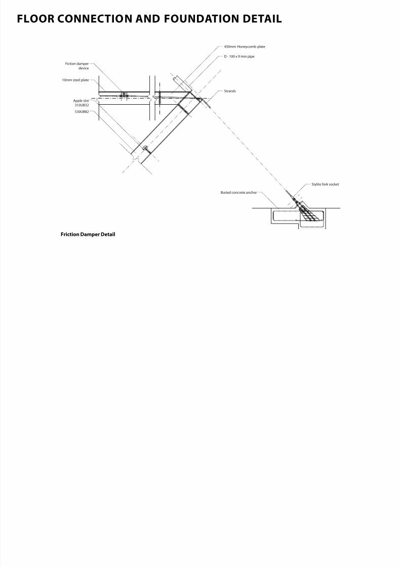
7/30/2019 121101 Kp Ppt Final
http://slidepdf.com/reader/full/121101-kp-ppt-final 118/122
Stylite fork socket
Strands
D - 100 x 9 mm pipe
450mm Honeycomb plate
530UB82
10mm steel plate
Apple slot
310UB32
Fiction damper
device
Buried concrete anchor
Friction Damper Detail
STRUCTURAL POTENTIAL | CHCH

7/30/2019 121101 Kp Ppt Final
http://slidepdf.com/reader/full/121101-kp-ppt-final 119/122
Suggest Possible
Material
Timber Steel Concrete
Soil Types Zoning Types
B-Business B-Industrial SP - Special
Purpose
L-Living CU-Cultural
Potential Function Size
S M L XLColumn Beam WallDiaphargm Structural
SystemMussel
Seismic Structure* Cladding*
1B.Cast SteelYielding Fuse
1B.ViscousDamper
2A.FrictionSpring
1C.FrictionDamper
2A.SlidingHinge Joint
2B.Modular Connector
2C.Hybrid LVLSystem
2D.PRESSS 2E.Cast SteelNode
3B.Slip-FrictionConnectors
4A.U-Shaped
Steel Damper 7 . Meta l 7 .Timber 7.Glazing 7.L ight
Concrete
Mussel Glass Sponge Dragonfly Wing ChitonSeahorse Tail Threespine Stickleback Mussel
Moving Structures Found in Nature

7/30/2019 121101 Kp Ppt Final
http://slidepdf.com/reader/full/121101-kp-ppt-final 120/122
EXTRUSION OF POSSIBLE BUILT
CHRISTCHURCH’S BUILDING ENVELOPE

7/30/2019 121101 Kp Ppt Final
http://slidepdf.com/reader/full/121101-kp-ppt-final 121/122
Building Area
Christchurch’s Building Envelope
CBD
CHRISTCHURCH’S BUILDING ENVELOPE
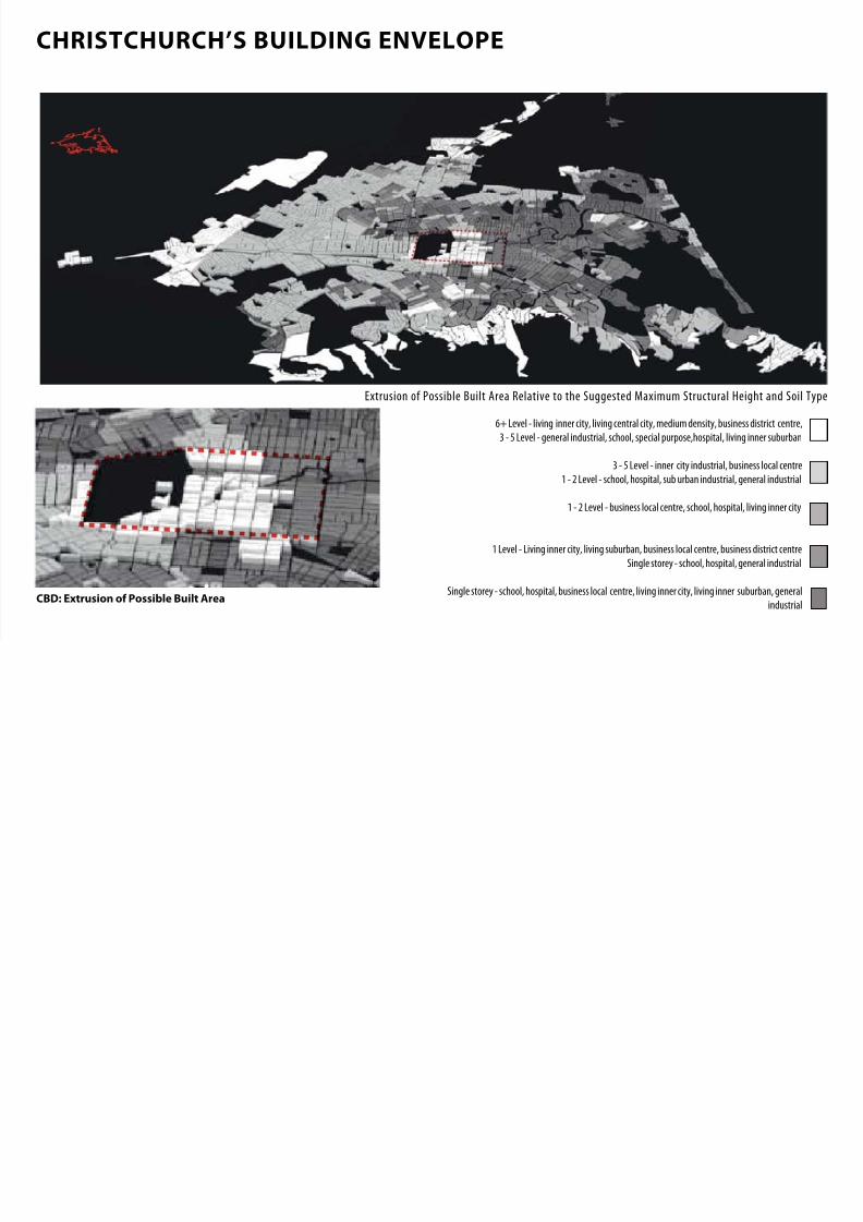
7/30/2019 121101 Kp Ppt Final
http://slidepdf.com/reader/full/121101-kp-ppt-final 122/122
6+ Level - living inner city, living central city, medium density, business district centre,
3 - 5 Level - general industrial, school, special purpose,hospital, living inner suburban
3 - 5 Level - inner city industrial, business local centre1 - 2 Level - school, hospital, sub urban industrial, general industrial
1 - 2 Level - business local centre, school, hospital, living inner city
Extrusion of Possible Built Area Relative to the Suggested Maximum Structural Height and Soil Type