120514 Rubber Ducky Water and Sewer Design Brief · The proposed campsites will connect to the...
57
Prepared By: R.J. Burnside & Associates Limited 106-B Scurfield Boulevard Winnipeg MB R3Y 1G4 Prepared for: Rubber Ducky Resort & Campground June 2012 File No: 300031279 The material in this report reflects best judgement in light of the information available at the time of preparation. Any use which a third party makes of this report, or any reliance on or decisions made based on it, are the responsibilities of such third parties. R.J. Burnside & Associates Limited accepts no responsibility for damages, if any, suffered by any third party as a result of decisions made or actions based on this report. Rubber Ducky Resort & Campground Water and Sewer Expansion Design Brief
Transcript of 120514 Rubber Ducky Water and Sewer Design Brief · The proposed campsites will connect to the...

Prepared By:
R.J. Burnside & Associates Limited 106-B Scurfield Boulevard Winnipeg MB R3Y 1G4
Prepared for:
Rubber Ducky Resort & Campground
June 2012
File No: 300031279
The material in this report reflects best judgement in light of the information available at the time of preparation. Any use which a third party makes of this report, or any reliance on or decisions made based on it, are the responsibilities of such third parties. R.J. Burnside & Associates Limited accepts no responsibility for damages, if any, suffered by any third party as a result of decisions made or actions based on this report.
Rubber Ducky Resort & Campground Water and Sewer Expansion Design Brief

Rubber Ducky Campground and Resort i Water and Sewer Expansion Design Brief June 2012
R.J. Burnside & Associates Limited 300031279
Table of Contents
1.0 Background........................................................................................................1 1.1. Project Description ........................................................................................... 1 1.2. Reason for Project ............................................................................................ 1
2.0 Existing Water System Description..................................................................2 2.1. Groundwater Source ........................................................................................ 2 2.1.1. GUDI Status of the Well .....................................................................................2 2.1.2. Water Quality......................................................................................................2 2.2. Disinfection & Treated Water Storage ............................................................. 4 2.3. Existing Water Consumption ........................................................................... 4 2.4. Projected Water Consumption......................................................................... 6 2.5. Chlorine Contact Time...................................................................................... 6
3.0 Proposed Water System Description ...............................................................8 3.1. Proposed Construction Schedule.................................................................... 9 3.2. Capacity of the Existing System ...................................................................... 9 3.2.1. Treated Water Storage Tanks............................................................................9 3.2.2. Distribution Pumps and Lines ........................................................................10 3.3. Protection of Public Health during Construction ..........................................10
4.0 Existing Wastewater System Description ......................................................12 4.1. Existing Wastewater Production ....................................................................12
5.0 Proposed Wastewater System Description....................................................15
Appendices
A Drawings
B Water Quality Data
C Well Drillers’ Log
D Relevant Correspondence
Drawing List
1.0 General Site Plan
2.0 Water & Sewer Servicing Plan
3.0 Water & Sewer Details and Specifications

Rubber Ducky Campground and Resort 1 Water and Sewer Expansion Design Brief June 2012
R.J. Burnside & Associates Limited 300031279
1.0 Background
1.1. Project Description
The Rubber Ducky Resort & Campground retained RJ Burnside & Associates Ltd. (RJB)
to complete Design Drawings and a Design Brief to satisfy the requirements of the
Manitoba Conservation and Water Stewardship Office of Drinking Water (ODW) to
obtain a Permit to Construct/Alter a Public Water System.
The campground is located along Road 76.5 in the RM of Woodlands, approximately
12 km west of Stonewall, MB (Refer to Drawing Cover Page in Appendix A). The
existing campground consists of 80 serviced RV campsites; 7 unserviced sites; 4 Bed
and Breakfast suites; and a restaurant/recreational centre building with public
washrooms and showers.
The project includes the expansion of the existing campground to include an additional
118 RV campsites with water and sewer servicing.
The Design Brief provides a description of the existing water and wastewater servicing,
the proposed expansion, and the project schedule. Following discussion with the ODW,
the existing system will be evaluated with respect to chlorine contact time and the
capacity of the existing system pumps.
1.2. Reason for Project
The existing Rubber Ducky Resort & Campground has been operating at maximum
capacity during recent summer seasons. The Owner has decided to install additional
campsites to meet the demand. A portion of the proposed campsites have been claimed
by deposit, with a substantial waiting list, indicating the demand for this expansion.
Serviced campsites with both water and sewer connections are required for long term
RV camping. The proposed campsites will connect to the existing water system, while
sewage servicing will be provided by new sewage holding tanks. Sewage holding tanks
will be pumped out as required with sewage hauled to the Warren Lagoon.

Rubber Ducky Campground and Resort 2 Water and Sewer Expansion Design Brief June 2012
R.J. Burnside & Associates Limited 300031279
2.0 Existing Water System Description
2.1. Groundwater Source
The existing water system draws raw water from a single well source located
approximately 30 m south of the recreational centre building (Refer to Drawing G1 in
Appendix A). The well was installed in 2005 by Interlake Water Supply. It consists of a
30.5 m (100 feet) deep, 150 mm PVC casing, with an open hole extending to a depth of
61 m (200 feet). At the time of the site visit the wellhead extended approximately 30 cm
above the ground level, and had positive grading around the wellhead.
Two drawdown tests are noted on the well drillers’ log. One test pumped at a rate of
614 L/min (135 imp. gallons/min) for 3 hours, and recorded a drawdown to 17.7 m (58
feet). The other test pumped at a rate of 909 L/min (200 imp. gallons/min) for 2 hours
and recorded a drawdown from an initial water level of 2.4 m (8 feet) to a final level of
22.9 m (75 feet). A copy of the well drillers’ log is included in Appendix C.
Water is pumped from the well by a 5 HP Franklin Electric submersible well pump
through a 50 mm polyethylene line to the pumphouse, located within the campground
recreational centre building.
2.1.1. GUDI Status of the Well
Based on a desktop analysis, the raw water supply well is not considered to be
groundwater under the direct influence of surface water (GUDI). The 2010 Water
System Audit Report indicated no exceedances for total coliform and E.Coli. in treated
and distribution water. The 2011 Audit Report noted that one treated water sample and
one distribution sample tested positive for total coliform, but re-samples from the same
location were negative.
Based on the criteria in Section 2(1)(b) of the Drinking Water Safety Regulation (CCSM
c D101), the well is not deemed to be GUDI, since:
• The well has a thick limestone overburden;
• It is not within 200 m of a surface water body;
• It is not in a karst or unconfined aquifer;
• It is not part of an enhanced recharge and infiltration project, and;
• It is a vertical, drilled well.
2.1.2. Water Quality
General chemistry samples from June 2010 for raw and treated water provided by the
Owner were reviewed to determine any aesthetic and health-based concerns. The key

Rubber Ducky Campground and Resort 3 Water and Sewer Expansion Design Brief June 2012
R.J. Burnside & Associates Limited 300031279
parameters from those sample results are summarized in Table 2.1, with the full results
included in Appendix B.
Based on these available testing results, the water exhibits levels at or near the
Guidelines for Canadian Drinking Water Quality (GCDWQ) limits for the aesthetic
parameters of iron and total dissolved solids. There were no exceedances found for
health-based maximum allowable concentrations.
The required free chlorine residual concentration for water leaving the treatment facility
is 0.5 mg/L. According to the 2010 Water System Audit Report the chlorine residual
concentration was in 95.8% compliance for that year, while the 2011 Audit Report
indicated 100% compliance.
Table 2.1 Rubber Ducky Campground Water System Raw and Treated Water Chemical Analysis
Sample Date: June 8, 2012 Parameter Units
Raw Treated
GCDWQ Maximum
Arsenic mg/L 0.00121 0.00122 0.01 MAC
Benzene mg/L <0.00050 - 0.005 MAC
Calcium mg/L 63.8 62.6
Chloride (Dissolved) mg/L 3.83 27.8 250 AO
Colour TCU <5.0 5.0 15 AO
Fluoride (Dissolved) mg/L 0.48 0.42 1.5 MAC
Hardness (as CaCO3) mg/L 431 429 500 AO Iron mg/L 0.702 0.627 0.3 AO
Lead mg/L 0.000533 0.000371 0.01 MAC
Magnesium mg/L 65.9 66.2
Manganese mg/L 0.00294 0.00290 0.05 AO
Nitrate & Nitrite-N (Dissolved)
mg/L 0.420 0.357 10 MAC
pH pH units 7.75 7.85 6.5 - 8.5 AO
Total Carbon mg/L 113 112
Total Inorganic Carbon
mg/L 117 113
Total Organic Carbon mg/L <1.0 <1.0 Total Dissolved Solids
mg/L 480 536 500 AO
Turbidity1 NTU 0.57 0.11 1.0 -
Uranium mg/L `0.00214 0.00212 0.02 IMAC 1 The turbidity guidelines from the GCDWQ do not apply to a non-GUDI groundwater source.
Results in bold and shaded in grey indicate parameters exceeding the CDWQG objective. IMAC = interim maximum acceptable concentration, MAC = maximum acceptable concentration, AO = aesthetic objective

Rubber Ducky Campground and Resort 4 Water and Sewer Expansion Design Brief June 2012
R.J. Burnside & Associates Limited 300031279
2.2. Disinfection & Treated Water Storage
Within the pumphouse, water is dosed with chlorine (12% sodium hypochorite solution)
before it is discharged into the 5680 L (1250 imp. gallon) treated water holding tank.
The Chem-Tech Series 100 chlorine dosing pump is adjusted by the Operator to
maintain a minimum 0.5 mg/L free chlorine residual concentration in water leaving the
pumphouse.
The treated water holding tank is filled with 15 ¾-inch baffle balls, which force the water
to follow a more circuitous path through the tank and improve the overall disinfection by
increasing contact time. The baffle ball supplier confirmed that the product is made from
FDA-approved polyethylene and are frequently used in liquid transport trucks.
There is a 2 HP Franklin Electric variable speed submersible pump in the treated water
storage tank which supplies the distribution system. The pressure for water entering the
distribution system is maintained at 360 kPa (52 psi).
2.3. Existing Water Consumption
The existing water consumption, including the average daily demand (ADD), maximum
daily demand (MDD) and peak hour flow (PHF) are important parameters in determining
the required size of the treated water storage, the required pumping capacity and design
of the distribution system.
The system does not have historical water flow records prior to 2012. However,
according to the campground owners, another similar campground recorded an average
water consumption of 83 L/day (22 US gallons/day) per campsite. No detailed records
were available from this site.
While Rubber Ducky Campground does not have historical water flow data, sewage
hauling was recorded in 2011 and was used to determine the average wastewater
production. This is discussed in detail in Section 4.1. This wastewater production can
also be used to inform the estimate for average and maximum day water consumption.
The average daily wastewater production from each campsite, based on the 2011
sewage hauling data, was 52 L/day when the campground is at full capacity (summer
weekend day). However, the owners reported that a portion of the water consumption is
used for activities such as gardening and watering lawns, and therefore would not enter
the wastewater holding tanks.
The Owners installed a water meter at the beginning of the 2012 season, and reported
measurements from the May Long Weekend shortly before the completion of the Design

Rubber Ducky Campground and Resort 5 Water and Sewer Expansion Design Brief June 2012
R.J. Burnside & Associates Limited 300031279
Brief. The maximum daily water consumption during this weekend, with the campground
at full capacity, was 2,700 L (31 L/campsite assuming all the water was used by the 87
campsites.)
Therefore, the average water consumption of 83 L/day per campsite is taken to be an
acceptable, conservative value, even though it is lower than typical values presented in
design literature such as the Ontario Ministry of the Environment (MOE) Design
Guidelines for Drinking Water Systems.
Based on discussion with the campground owners, other sources of water demand can
be summarized as follows:
• Water consumption from the public toilets and washroom sinks is 880 L/day
(assuming 20 users for each of the men’s and ladies’ washrooms.)
• Water consumption from the public showers would be 190 L/day (assuming 5
total users, 5 minute showers, with low flow (7.6 L/min) shower heads).
• Water consumption by the restaurant is 200 L/day.
• The campground owners’ house with 4 residents is assumed to have a water
consumption of 225 L/capita/day, or 900 L/day.
• The 4 Bed and Breakfast units are assumed to have water consumption
equivalent to 450 L/day, assuming occupancy of 2 people and a water
consumption of 225 L/capita/day.
• The 7 unserviced campsites are assumed to have water consumption equivalent
to a serviced campsite.
The total average daily demand (ADD) is estimated to be 11,191 L/day (11.2 m3/day).
The Ontario Ministry of the Environment (MOE) Design Guidelines also provide
recommendations for the maximum day factor and peak hour factor. The rationale for
using these Ontario guidelines is that they provide specific recommendations for small
systems serving under 500 people. The recommendations are summarized below in
Table 2.2.
Table 2.2 Peak Hour Factors for Small Systems
# Dwelling Units Serviced
Maximum Day Factor
Peak Hour Factor
10 9.5 14.3
50 4.9 7.4
100 3.6 5.4
150 3.0 4.5
167 2.9 4.3 Source: MOE Design Guidelines for Drinking Water Systems (2008)

Rubber Ducky Campground and Resort 6 Water and Sewer Expansion Design Brief June 2012
R.J. Burnside & Associates Limited 300031279
The number of dwelling units is taken to be 91, based on the 87 campsites and 4 Bed &
Breakfast units. Using linear interpolation of the above figures from Table 2.2, the
Maximum Day Factor is 3.8, and the Peak Hour Factor is 5.8. Applying these factors,
the MDD is 42.6 m3/day, and the Peak Hour Flow is 45.1 L/min.
2.4. Projected Water Consumption
The proposed campground expansion will add an additional 118 serviced campsites.
Assuming the same design water consumption of 83 L/day/campsite, this would be an
additional daily demand of 9.8 m3/day, for a total projected ADD of 21.0 m3/day. With a
projected population of above 500 when the expanded campground is at full capacity,
using the MOE Design Guidelines, the Maximum Day Factor would be 2.75 and the
Peak Hour Factor would be 4.13. The projected MDD is therefore 57.8 m3/day and the
projected Peak Hour Flow is 60.2 L/min.
2.5. Chlorine Contact Time
Chlorine contact time is required by Manitoba law to ensure the system provides
effective disinfection. The requirement for a secure groundwater source is 20 minutes of
effective chlorine contact time at the peak hour flow rate.
The peak hourly flow rate, as discussed above, is taken to be 45.1 L/min for the existing
system and 60.2 L/min for the system after the proposed expansion.
The actual volume of the treated water storage tank is 1250 imperial gallons (5680 L).
The effective volume of the tank is obtained by multiplying the actual volume by a
baffling factor. The Office of Drinking Water advised that a contact time study is planned
to determine the baffling factor for baffle balls such as those used in Rubber Ducky
Campground, but that an interim value of 0.3 should be used (Refer to correspondence
in Appendix D).
The chlorine contact time for the existing system is determined by the calculation below:
[Contact time] = [Storage volume] * [Baffling factor] / [Peak hour flow rate]
= (5680 L) * (0.3) / (45.1 L/min)
= 37.8 min

Rubber Ducky Campground and Resort 7 Water and Sewer Expansion Design Brief June 2012
R.J. Burnside & Associates Limited 300031279
While the contact time for the system including the proposed expansion is:
= (5680 L) * (0.3) / (60.2 L/min)
= 28.3 min
Therefore the system meets the requirement for 20 minutes of contact time for the
existing system and the proposed expansion.
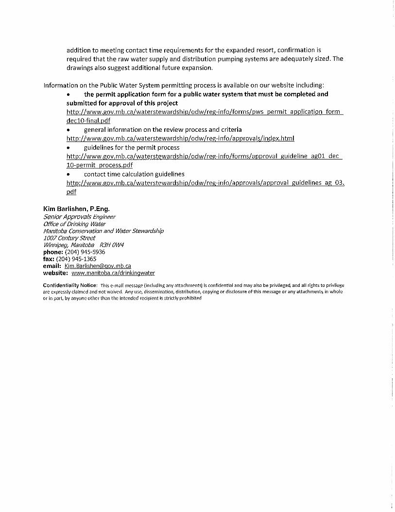
Through communication with Kim Barlishen from the Office if Drinking Water it was
noted that the actual and projected water consumption values per campsite are lower
than design values form available literature, and that there is limited data available to
accurately document the typical consumption in an RV campground. However, it was
also noted that some campgrounds are beginning to install meters and record this data,
including Rubber Ducky Campground. Therefore, it is recommended that the above
contact time calculations be reviewed at the end of the 2012 season and revised if
necessary based on the data from the system itself. Additionally, if a study is completed
by the province to determine the baffling factor provided by baffle balls, the results
should also be used to revise the calculations. If the revised calculations result in the
need to upgrade the treated water storage system, this would be completed after the
2012 season has ended.
Waiver of Baffling Factor
The Director of the Office of Drinking Water approved a policy that allows certain public
water systems to calculate the hydraulic retention time of the contact tank without
applying a baffling factor. To be eligible the system must meet the following criteria:
• Seasonal system
• Serves fewer than 500 people
• Uses a secure groundwater source (i.e. no indication of bacterial contamination)
• Individually approved by the Office of Drinking Water to calculate hydraulic
retention time in this manner
The Office of Drinking Water has confirmed that the baffling factor would need to be
considered if the proposed expansion caused the projected occupancy of the
campground at peak conditions to rise above 500 people. Based on an occupancy of 3
persons/ campsite, this would allow a maximum of 166 campsites maintaining a
population under 500, or 75 additional campsites beyond the existing 87 campsites and
4 Bed & Breakfast suites. However, based on the calculations above, even with the
baffling factor of 0.3 considered, the existing treated water storage tank provides
adequate contact time to meet Manitoba regulations.

Rubber Ducky Campground and Resort 8 Water and Sewer Expansion Design Brief June 2012
R.J. Burnside & Associates Limited 300031279
3.0 Proposed Water System Description
The proposed upgrade to the water system consists of a major expansion to the
distribution system to service 118 proposed new RV campsites. No changes will be
made to the existing well source or pumphouse.
The design for the distribution system expansion was completed with general
conformance to the Ten State Standards. Some deviations from the Ten State
Standards were justified due to the small scale and seasonal nature of the system, and
the lower water consumption when compared to a municipal application. The deviations
are identified as appropriate below.
The expanded campground area is located to the west of the existing facility. It will be
connected to the existing distribution system through a 50 mm CSA Series 75
polyethylene watermain to be connected and an existing curb stop and installed by
directional drilling. The location of the directional drilling line is shown in Drawing SW1
in Appendix A.
The watermains will be shallow bury, with a minimum depth of 0.5 m. The Ten State
Standards recommend sufficient cover or insulation to prevent freezing. However, the
system will operate seasonally, and therefore it is not necessary to provide freeze
protection. The watermains will be shock chlorinated and flushed prior to the beginning
of each season, and drained at the end of the season.
All watermains will be 50 mm or 32 mm CSA Series 75 polyethylene, while services will
be 19 mm polyethylene with an individual standpipe service connection provided at each
campsite (refer to water service detail in SW2 in Appendix A). Where possible
watermains will be connected in loops to improve circulation in the system and reduce
the risk of water remaining stagnant in the watermain at a dead end, leading to a loss of
chlorine residual. As recommended in the Ten State Standards, where it is not possible
to avoid a dead end means will be provided to flush the line. One dead end is present in
the cul-de-sac containing Campsites 111-118 (refer to Drawing SW1 in Appendix A).
This dead end will be flushed via a 50 mm valve located at the end of the main line.
The Ten State Standards recommend continuous and uniform bedding, tamped in
layers, for all buried pipe. However, this system will be shallow bury with small diameter
pipe and will be used seasonally. Therefore, it is recommended that pipe be installed as
per the manufacturer’s recommendations, with installation at a uniform grade to
minimize local high and low points to limit air accumulation, but that compacted bedding
material is not required along the full length of the watermains. The Ten State
Standards also recommend the use of air relief valves at all high points in the water
lines. However, due to the seasonal use of the system, with the distribution system

Rubber Ducky Campground and Resort 9 Water and Sewer Expansion Design Brief June 2012
R.J. Burnside & Associates Limited 300031279
drained each fall, and flushed and recharged each spring, air relief valves were not
included in the design.
Control valves will be installed along the watermain as shown in Drawing SW1 to allow
for isolation of watermain sections for repair or maintenance. The Ten State Standards
recommend a maximum valve spacing of 244 m (800 feet), which is achieved in the
proposed system.
The Ten State Standards recommend a minimum watermain diameter of 75 mm (3”)
unless justified by hydraulic analysis and in special circumstances. Given the seasonal
operation of the system, and based on head loss calculations to the farthest point in the
distribution system, 50 mm and 32 mmwatermains were determined to be appropriate.
The Ten State Standards also recommend reaction blocking, tie rods or joints designed
to prevent movement at all tees, bends and plugs. Based on the seasonal application of
the system, low average flows and small diameter pipe, adequately compacted bedding
material at these locations was considered an appropriate alternative.
3.1. Proposed Construction Schedule
Time is of the essence for this project. The Owner has indicated an intention to install
the new distribution system lines as soon as the permit is issued, with completion of the
installation prior to the required in-service date of July 1, 2012.
3.2. Capacity of the Existing System
The Office of Drinking Water requested that this Design Brief discuss the capacity of the
existing treatment system to support the additional load from the proposed expansion.
In particular, the size of the treated water storage tank and the capacity of the
distribution pumps were to be discussed.
3.2.1. Treated Water Storage Tanks
As calculated above, the existing baffled treated water storage tank is projected to
provide a contact time of 28.3 minutes after the full campground expansion is complete.
Therefore the installation of an additional treated water storage tank is not required.
As noted, it is recommended that this be reviewed once additional data on the water
consumption and baffling factor are available.

Rubber Ducky Campground and Resort 10 Water and Sewer Expansion Design Brief June 2012
R.J. Burnside & Associates Limited 300031279
3.2.2. Distribution Pumps and Lines
The water line from the pumphouse to the existing curb stop is a 50 mm line, while the
secondary watermains off the central line are 32 mm. A head loss calculation was
completed to determine the anticipated pressure drop for water to the farthest point in
the expanded distribution system. The calculation was based on the conservative
assumption that 100% of the expanded campground peak flow (29.5 L/min) would flow
along the central watermain and a peak flow proportional to the number of campsites on
each separate loop would flow along the watermain loop to the farthest points in the
distribution system. An additional factor was applied to account for losses due to fittings
and valves. Based on these assumptions the pressure loss was projected to be no
greater than 35 kPa (5.0 psi) under peak conditions.
The Ten State Standards require a minimum pressure of 240 kPa (35 psi) to be
maintained in the distribution system under normal operating conditions. With the
pressure set at 360 kPa (52 psi) in the pumphouse, it is not anticipated that the system
will have difficulties meeting this requirement.
A pump curve for the 2 HP distribution pump was not available. While no documentation
was available, the Owner reported that the nominal flow of the pump was 189 L/min
(50 USGPM). Based on the pump curve for another model of submersible pump with a
2 HP motor, and based on the projected peak hour flow, it is anticipated that the pump
will be of sufficient size. Confirmation that the pump capacity is adequate will be
acquired by operation of the system; if the pressure in the distribution system falls below
240 kPa (35 psi) during peak conditions a larger distribution pump may be required.
The well supply pump, with a 5 HP motor, will be of sufficient size to meet the projected
system demands, as its pumping capacity is greater than that of the 2 HP distribution
pump.
3.3. Protection of Public Health during Construction
The expansion of the distribution system will be completed in such a manner as to not
impact the existing system. The tie-in point, the curb stop located in the existing
campground area (Refer to Drawing SW1 in Appendix A) will be closed while the new
watermains are installed, so the existing system is able to operate normally.
After the new watermains and services are installed, the system should be disinfected
through shock chlorination, using the same procedure that is used at the beginning of
each season. The following procedures should be followed:
• During construction, protect exposed pipe ends to prevent excess water or debris
from entering.

Rubber Ducky Campground and Resort 11 Water and Sewer Expansion Design Brief June 2012
R.J. Burnside & Associates Limited 300031279
• Pump chlorinated water, with a residual of at least 50 mg/L, into the system,
bleeding water through all outlets.
• Thoroughly flush the water lines and services with normal chlorinated water (0.5
mg/L residual) before the system is put into service.
• Collect representative samples from the distribution system for bacteriological
analysis.
If the shock chlorination of the expanded campground area requires a shutdown of the
entire campground water system, the regional Office of Drinking Water representative
should be contacted to review the planned procedure.

Rubber Ducky Campground and Resort 12 Water and Sewer Expansion Design Brief June 2012
R.J. Burnside & Associates Limited 300031279
4.0 Existing Wastewater System Description
The existing wastewater disposal system consists of five 1500 imp. gallon (6819 L)
holding tanks. The holding tanks are pumped out as required, with the sewage taken to
the Warren Lagoon. The lagoon has provided authorization to the Rubber Ducky
Campground to discharge sewage there.
Each campsite is serviced by a 100 mm SDR wastewater connection. The sewage
mains in the system are also 100 mm. The system owners reported that they have had
no operational concerns related to sewermains becoming plugged during their operation
of the facility (7 years).
4.1. Existing Wastewater Production
While the Rubber Ducky Campground began to record water flow data in 2012, sewage
hauling was recorded in 2011 (Table 4.1) and can be used to determine the average
wastewater production. This wastewater production can also be used to determine an
estimate for average and maximum day water consumption.
Table 4.1 Rubber Ducky Campground
2011 Sewage Holding Tank Pumpout Records
Date Number of Loads
(1500 imp. gallons each)
May 3 4
May 17 3
May 23 4
June 2 4
June 7 2
June 14 3
June 23 2
July 7 3
July 13 1
July 20 2
July 27 4
Aug 3 3
Aug 9 3
Aug 22 3
Sep 1 3
Sep 9 2
Sep 16 1
Sep 23 1
Sep 29 1
Oct 5 3
TOTAL 52

Rubber Ducky Campground and Resort 13 Water and Sewer Expansion Design Brief June 2012
R.J. Burnside & Associates Limited 300031279
There were a total of 52 loads over a period of 155 days. Based on the conservative
assumption that each load represents 100% of the maximum capacity (6819 L), the total
sewage volume was 354,588 L for the 2011 season. The pumpouts occurred
approximately each week, with the largest weekly pumpout being 4 loads, or 27,276 L.
To determine the maximum day wastewater production, it was considered that weekend
days (Saturday or Sunday) would be operating at peak capacity, while weekdays
(Monday to Friday) would operate at 30% of the peak capacity. The May 23 pumpout
date covers the “May long weekend” period which is assumed to include 3 days at full
capacity. Therefore, the July 27 pumpout date is considered to be the critical date with
the highest peak day wastewater generation in the preceding week.
Based on discussion with the campground owners, the following assumptions were used
to determine the peak day wastewater generation:
• Wastewater production from the toilets and washroom sinks would be 880 L/day
(assuming 20 users for each of the men’s and ladies’ washrooms.
• Wastewater production from the showers would be 190 L/day (assuming 5 total
users, 5 minute showers, with low flow (7.6 L/min) shower heads).
• Wastewater generation in the restaurant is 200 L/day.
• The campground owners’ house with 4 residents is also connected to the holding
tank at the recreational centre. Therefore their wastewater generation is included
in the pumpout figures above. The wastewater production at the house is
assumed to be 225 L/capita/day, or 900 L/day. This value is at the low end of
typical average day water consumption values, and will apply to both weekend
days and weekdays.
• The remaining wastewater is assumed to originate from the campgrounds and
Bed & Breakfast units.
• The 4 Bed and Breakfast units are assumed to have wastewater production
equivalent to a campsite.
• The 7 unserviced campsites are assumed to have wastewater production
equivalent to a serviced campsite. These sites discharge sewage via on-board
containers to the northwest holding tank.
Based on the above assumptions, the calculations to determine the peak day
wastewater production are summarized in Table 4.2.

Rubber Ducky Campground and Resort 14 Water and Sewer Expansion Design Brief June 2012
R.J. Burnside & Associates Limited 300031279
Table 4.2 Rubber Ducky Campground
Peak Day Wastewater Production Volumes
Wastewater Source Weekend Day
(100% capacity) Weekday
(30% capacity)
Total (2 weekend days and
5 weekdays)
Washrooms 880 264 3080
Showers 190 57 665
Restaurant 200 60 700
House 900 900 6300
Bed & Breakfast units (4)
208 (52 L/unit)
62 726
Campsites (87) 4516
(52 L/site) 1355 15807
Total 6,894 2,698 27,278 All units are litres (L)
As shown in Table 4.2, the maximum day (peak July weekend) wastewater production is
calculated to be 6,894 L. These calculations indicate a wastewater production of
52 L/campsite.
The proposed expansion would add an additional 118 RV campsites for a total of
205 campsites. The entire expansion area would operate seasonally. Assuming a
similar wastewater production in the new campsites of 52 L/day per campsite, the
projected peak daily wastewater production for the expanded facility, including existing
sites, would be13,030 L/day.

Rubber Ducky Campground and Resort 15 Water and Sewer Expansion Design Brief June 2012
R.J. Burnside & Associates Limited 300031279
5.0 Proposed Wastewater System Description
The proposed campground expansion will be serviced by individual wastewater holding
tanks to be shared between two campsites each. The tanks will be located between
each pair of campsites, with a 100 mm service to a service connection at each site (refer
to Drawing SW1 for the holding tank layout and Drawing SW2 in Appendix A for the
wastewater service connection detail).
This system was selected for its simplicity, and to avoid the need for manholes and large
diameter sewermains specified in the Ten State Standards. All wastewater treatment
will be handled off site at the Warren Lagoon.
To reduce the risk of contamination from a damaged line, the proposed wastewater
holding tanks will be installed with a minimum of 3.0 m separation from watermains and
water services. The wastewater services will have a minimum of 1.0 m separation from
water service lines, while the water and wastewater service connections will have a
minimum 3.0 m separation (refer to site servicing plan detail on Drawing SW2 in
Appendix A). Where it is necessary for water and wastewater lines to cross, the water
line will pass a minimum of 450 mm above the sewer line.
Appendix A
Drawings

RUBBER DUCKY RESORT & CAMPGROUND
DRAWING LIST
G-1 GENERAL SITE PLAN
WS-1 WATER & SEWER
SERVICING PLAN
RM OF WOODLANDS, MANITOBA
R. J. Burnside & Associates Limited
106B Scurfield Blvd., Winnipeg, Manitoba
telephone (204) 949-7110 fax (204) 949-7111
web www.rjburnside.com
WS-2 WATER & SEWER DETAILS
AND SPECIFICATIONS
WATER & SEWER EXPANSION
JOB# 300031279

PRELIMINARY
FOR DISCUSSION
PURPOSES ONLY
R. J. Burnside & Associates Limited
106 B Scurfield Blvd, Winnipeg MB R3Y 1G4
telephone (204) 949-7110 fax (204) 949-7111
G-1

2
4
6
.
4
0
m
2
4
6
.
0
0
m
2
4
6
.
0
0
m
246.0
0m
2
4
7
.0
0
m
2
4
7
.0
0
m
2
4
6
.2
0
m
2
4
6
.2
0
m
246.20m
246.20m
2
4
6
.
4
0
m
246.40m
2
4
6
.4
0
m
2
4
6
.
6
0
m
2
4
6
.
6
0
m
2
4
6
.
6
0
m
2
4
6
.8
0
m
HP HP
R. J. Burnside & Associates Limited
106 B Scurfield Blvd, Winnipeg MB R3Y 1G4
telephone (204) 949-7110 fax (204) 949-7111
WS-1
XX
PRELIMINARY
FOR DISCUSSION
PURPOSES ONLY

PRELIMINARY
FOR DISCUSSION
PURPOSES ONLY
R. J. Burnside & Associates Limited
106 B Scurfield Blvd, Winnipeg MB R3Y 1G4
telephone (204) 949-7110 fax (204) 949-7111
WS-2
N.T.S.
N.T.S.
N.T.S.

Appendix B
Water Quality Data


Appendix C
Well Drillers’ Log


Appendix D
Relevant Correspondence