
1204 - Section 01.pdf
158
Operator's Manual i Section 1 - Operating Instructions Table Of Contents Crane Nomenclature 1-1 ....................................................................... Operating Safety 1-1 ........................................................................... General Safety Rules 1-2 ....................................................................... Operator Awareness 1-2 ...................................................................... Electrical Dangers 1-7 ........................................................................ Radio Frequency Or Electro Magnetic Interference (RFI Or EMI) 1-10 ................................ Protective Equipment 1-10 ..................................................................... Signal Persons And Bystanders 1-10 ............................................................ Crane Inspections And Adjustments 1-11 ........................................................ Wire Rope 1-13 ............................................................................... Crane And Area Clearance 1-13 ................................................................ Weights, Lengths, And Radii 1-14 ............................................................... Traveling 1-18 ................................................................................ Leaving The Station 1-19 ...................................................................... Personnel Handling Guidelines 1-20 .............................................................. Introduction 1-20 ............................................................................. Authorization 1-20 ............................................................................ Equipment 1-20 .............................................................................. Maintenance, Lubrication, And Adjustments 1-21 ................................................. Inspection And Rigging 1-21 ................................................................... Crane Test Procedures 1-22 .................................................................... Operation And Safety 1-23 ..................................................................... Additional Requirements For Offshore Cranes 1-24 ................................................ Operator's Cab 1-27 ............................................................................ Bubble Level 1-27 .............................................................................. Fire Extinguisher 1-27 ........................................................................... RCL Overhead Light Bar (If Equipped) 1-27 ........................................................ External RCL Light Bar (If Equipped) 1-27 ......................................................... First Aid Kit 1-27 ............................................................................... Top Hatch 1-27 ................................................................................ Top Hatch Wiper And Washer 1-27 .............................................................. Top Hatch Window 1-27 ....................................................................... Top Hatch Sunscreen 1-27 .....................................................................
Transcript of 1204 - Section 01.pdf

Operator's Manual
iSection 1 - Operating Instructions
Table Of ContentsCrane Nomenclature 1-1. . . . . . . . . . . . . . . . . . . . . . . . . . . . . . . . . . . . . . . . . . . . . . . . . . . . . . . . . . . . . . . . . . . . . . .
Operating Safety 1-1. . . . . . . . . . . . . . . . . . . . . . . . . . . . . . . . . . . . . . . . . . . . . . . . . . . . . . . . . . . . . . . . . . . . . . . . . . .
General Safety Rules 1-2. . . . . . . . . . . . . . . . . . . . . . . . . . . . . . . . . . . . . . . . . . . . . . . . . . . . . . . . . . . . . . . . . . . . . . .
Operator Awareness 1-2. . . . . . . . . . . . . . . . . . . . . . . . . . . . . . . . . . . . . . . . . . . . . . . . . . . . . . . . . . . . . . . . . . . . . .
Electrical Dangers 1-7. . . . . . . . . . . . . . . . . . . . . . . . . . . . . . . . . . . . . . . . . . . . . . . . . . . . . . . . . . . . . . . . . . . . . . . .
Radio Frequency Or Electro Magnetic Interference (RFI Or EMI) 1-10. . . . . . . . . . . . . . . . . . . . . . . . . . . . . . . .
Protective Equipment 1-10. . . . . . . . . . . . . . . . . . . . . . . . . . . . . . . . . . . . . . . . . . . . . . . . . . . . . . . . . . . . . . . . . . . . .
Signal Persons And Bystanders 1-10. . . . . . . . . . . . . . . . . . . . . . . . . . . . . . . . . . . . . . . . . . . . . . . . . . . . . . . . . . . .
Crane Inspections And Adjustments 1-11. . . . . . . . . . . . . . . . . . . . . . . . . . . . . . . . . . . . . . . . . . . . . . . . . . . . . . . .
Wire Rope 1-13. . . . . . . . . . . . . . . . . . . . . . . . . . . . . . . . . . . . . . . . . . . . . . . . . . . . . . . . . . . . . . . . . . . . . . . . . . . . . . .
Crane And Area Clearance 1-13. . . . . . . . . . . . . . . . . . . . . . . . . . . . . . . . . . . . . . . . . . . . . . . . . . . . . . . . . . . . . . . .
Weights, Lengths, And Radii 1-14. . . . . . . . . . . . . . . . . . . . . . . . . . . . . . . . . . . . . . . . . . . . . . . . . . . . . . . . . . . . . . .
Traveling 1-18. . . . . . . . . . . . . . . . . . . . . . . . . . . . . . . . . . . . . . . . . . . . . . . . . . . . . . . . . . . . . . . . . . . . . . . . . . . . . . . .
Leaving The Station 1-19. . . . . . . . . . . . . . . . . . . . . . . . . . . . . . . . . . . . . . . . . . . . . . . . . . . . . . . . . . . . . . . . . . . . . .
Personnel Handling Guidelines 1-20. . . . . . . . . . . . . . . . . . . . . . . . . . . . . . . . . . . . . . . . . . . . . . . . . . . . . . . . . . . . . .
Introduction 1-20. . . . . . . . . . . . . . . . . . . . . . . . . . . . . . . . . . . . . . . . . . . . . . . . . . . . . . . . . . . . . . . . . . . . . . . . . . . . .
Authorization 1-20. . . . . . . . . . . . . . . . . . . . . . . . . . . . . . . . . . . . . . . . . . . . . . . . . . . . . . . . . . . . . . . . . . . . . . . . . . . .
Equipment 1-20. . . . . . . . . . . . . . . . . . . . . . . . . . . . . . . . . . . . . . . . . . . . . . . . . . . . . . . . . . . . . . . . . . . . . . . . . . . . . .
Maintenance, Lubrication, And Adjustments 1-21. . . . . . . . . . . . . . . . . . . . . . . . . . . . . . . . . . . . . . . . . . . . . . . . .
Inspection And Rigging 1-21. . . . . . . . . . . . . . . . . . . . . . . . . . . . . . . . . . . . . . . . . . . . . . . . . . . . . . . . . . . . . . . . . . .
Crane Test Procedures 1-22. . . . . . . . . . . . . . . . . . . . . . . . . . . . . . . . . . . . . . . . . . . . . . . . . . . . . . . . . . . . . . . . . . . .
Operation And Safety 1-23. . . . . . . . . . . . . . . . . . . . . . . . . . . . . . . . . . . . . . . . . . . . . . . . . . . . . . . . . . . . . . . . . . . . .
Additional Requirements For Offshore Cranes 1-24. . . . . . . . . . . . . . . . . . . . . . . . . . . . . . . . . . . . . . . . . . . . . . . .
Operator's Cab 1-27. . . . . . . . . . . . . . . . . . . . . . . . . . . . . . . . . . . . . . . . . . . . . . . . . . . . . . . . . . . . . . . . . . . . . . . . . . . .
Bubble Level 1-27. . . . . . . . . . . . . . . . . . . . . . . . . . . . . . . . . . . . . . . . . . . . . . . . . . . . . . . . . . . . . . . . . . . . . . . . . . . . . .
Fire Extinguisher 1-27. . . . . . . . . . . . . . . . . . . . . . . . . . . . . . . . . . . . . . . . . . . . . . . . . . . . . . . . . . . . . . . . . . . . . . . . . . .
RCL Overhead Light Bar (If Equipped) 1-27. . . . . . . . . . . . . . . . . . . . . . . . . . . . . . . . . . . . . . . . . . . . . . . . . . . . . . . .
External RCL Light Bar (If Equipped) 1-27. . . . . . . . . . . . . . . . . . . . . . . . . . . . . . . . . . . . . . . . . . . . . . . . . . . . . . . . .
First Aid Kit 1-27. . . . . . . . . . . . . . . . . . . . . . . . . . . . . . . . . . . . . . . . . . . . . . . . . . . . . . . . . . . . . . . . . . . . . . . . . . . . . . .
Top Hatch 1-27. . . . . . . . . . . . . . . . . . . . . . . . . . . . . . . . . . . . . . . . . . . . . . . . . . . . . . . . . . . . . . . . . . . . . . . . . . . . . . . .
Top Hatch Wiper And Washer 1-27. . . . . . . . . . . . . . . . . . . . . . . . . . . . . . . . . . . . . . . . . . . . . . . . . . . . . . . . . . . . . .
Top Hatch Window 1-27. . . . . . . . . . . . . . . . . . . . . . . . . . . . . . . . . . . . . . . . . . . . . . . . . . . . . . . . . . . . . . . . . . . . . . .
Top Hatch Sunscreen 1-27. . . . . . . . . . . . . . . . . . . . . . . . . . . . . . . . . . . . . . . . . . . . . . . . . . . . . . . . . . . . . . . . . . . . .

Operator's Manual
ii Section 1 - Operating Instructions
RCL Control Module Diagnostic Connector 1-28. . . . . . . . . . . . . . . . . . . . . . . . . . . . . . . . . . . . . . . . . . . . . . . . . . .
Cab Electrical Center 1-28. . . . . . . . . . . . . . . . . . . . . . . . . . . . . . . . . . . . . . . . . . . . . . . . . . . . . . . . . . . . . . . . . . . . . . .
Cab Fuse Box 1-29. . . . . . . . . . . . . . . . . . . . . . . . . . . . . . . . . . . . . . . . . . . . . . . . . . . . . . . . . . . . . . . . . . . . . . . . . . . .
Cab Control Console 1-30. . . . . . . . . . . . . . . . . . . . . . . . . . . . . . . . . . . . . . . . . . . . . . . . . . . . . . . . . . . . . . . . . . . . . . .
RCL Display Diagnostic Connector 1-32. . . . . . . . . . . . . . . . . . . . . . . . . . . . . . . . . . . . . . . . . . . . . . . . . . . . . . . . . . .
Engine Diagnostic Connector 1-32. . . . . . . . . . . . . . . . . . . . . . . . . . . . . . . . . . . . . . . . . . . . . . . . . . . . . . . . . . . . . . .
Crane Control Display (CCD) Diagnostic Connector 1-32. . . . . . . . . . . . . . . . . . . . . . . . . . . . . . . . . . . . . . . . . . . .
Upper & Boom Floodlights (If Equipped) 1-33. . . . . . . . . . . . . . . . . . . . . . . . . . . . . . . . . . . . . . . . . . . . . . . . . . . . . .
Winch And Rear View Cameras 1-34. . . . . . . . . . . . . . . . . . . . . . . . . . . . . . . . . . . . . . . . . . . . . . . . . . . . . . . . . . . . . .
Crane Control Display 1-35. . . . . . . . . . . . . . . . . . . . . . . . . . . . . . . . . . . . . . . . . . . . . . . . . . . . . . . . . . . . . . . . . . . . . .
Engine Data And Aftertreatment Control Screen 1-38. . . . . . . . . . . . . . . . . . . . . . . . . . . . . . . . . . . . . . . . . . . . . .
Crane Control Display Brightness Adjustment 1-40. . . . . . . . . . . . . . . . . . . . . . . . . . . . . . . . . . . . . . . . . . . . . . . .
Diesel Particulate Filter (DPF) 1-41. . . . . . . . . . . . . . . . . . . . . . . . . . . . . . . . . . . . . . . . . . . . . . . . . . . . . . . . . . . . . . . .
Engine DPF Regeneration Indicators 1-41. . . . . . . . . . . . . . . . . . . . . . . . . . . . . . . . . . . . . . . . . . . . . . . . . . . . . . . .
High Exhaust System Temperature Indicator Light 1-42. . . . . . . . . . . . . . . . . . . . . . . . . . . . . . . . . . . . . . . . . . . .
Engine DPF Regeneration Inhibit Switch 1-42. . . . . . . . . . . . . . . . . . . . . . . . . . . . . . . . . . . . . . . . . . . . . . . . . . . .
DPF (Parked) Manual Regeneration 1-44. . . . . . . . . . . . . . . . . . . . . . . . . . . . . . . . . . . . . . . . . . . . . . . . . . . . . . . .
Seat Console Control Switches 1-46. . . . . . . . . . . . . . . . . . . . . . . . . . . . . . . . . . . . . . . . . . . . . . . . . . . . . . . . . . . . . .
Radio Operation 1-48. . . . . . . . . . . . . . . . . . . . . . . . . . . . . . . . . . . . . . . . . . . . . . . . . . . . . . . . . . . . . . . . . . . . . . . . . . .
Bass, Treble, Balance, And Fader Adjustment 1-50. . . . . . . . . . . . . . . . . . . . . . . . . . . . . . . . . . . . . . . . . . . . . . .
Initial Volume Adjustment 1-50. . . . . . . . . . . . . . . . . . . . . . . . . . . . . . . . . . . . . . . . . . . . . . . . . . . . . . . . . . . . . . . . . .
Radio Frequency Area Selection 1-50. . . . . . . . . . . . . . . . . . . . . . . . . . . . . . . . . . . . . . . . . . . . . . . . . . . . . . . . . . .
Beep ON, Beep 2ND Feature 1-50. . . . . . . . . . . . . . . . . . . . . . . . . . . . . . . . . . . . . . . . . . . . . . . . . . . . . . . . . . . . . .
Setting An Alarm 1-50. . . . . . . . . . . . . . . . . . . . . . . . . . . . . . . . . . . . . . . . . . . . . . . . . . . . . . . . . . . . . . . . . . . . . . . . .
Weather Band 1-50. . . . . . . . . . . . . . . . . . . . . . . . . . . . . . . . . . . . . . . . . . . . . . . . . . . . . . . . . . . . . . . . . . . . . . . . . . .
Public Address (PA) Feature 1-51. . . . . . . . . . . . . . . . . . . . . . . . . . . . . . . . . . . . . . . . . . . . . . . . . . . . . . . . . . . . . . .
Operator's Seat 1-53. . . . . . . . . . . . . . . . . . . . . . . . . . . . . . . . . . . . . . . . . . . . . . . . . . . . . . . . . . . . . . . . . . . . . . . . . . . .
First Aid Kit 1-53. . . . . . . . . . . . . . . . . . . . . . . . . . . . . . . . . . . . . . . . . . . . . . . . . . . . . . . . . . . . . . . . . . . . . . . . . . . . . . . .
Operator's Manual Holder 1-53. . . . . . . . . . . . . . . . . . . . . . . . . . . . . . . . . . . . . . . . . . . . . . . . . . . . . . . . . . . . . . . . . .
Crane Rating Manual Holder 1-53. . . . . . . . . . . . . . . . . . . . . . . . . . . . . . . . . . . . . . . . . . . . . . . . . . . . . . . . . . . . . . . .
Crane System Controls 1-55. . . . . . . . . . . . . . . . . . . . . . . . . . . . . . . . . . . . . . . . . . . . . . . . . . . . . . . . . . . . . . . . . . . . .
Horn Button 1-55. . . . . . . . . . . . . . . . . . . . . . . . . . . . . . . . . . . . . . . . . . . . . . . . . . . . . . . . . . . . . . . . . . . . . . . . . . . . . . .
Engine Throttle Controls 1-55. . . . . . . . . . . . . . . . . . . . . . . . . . . . . . . . . . . . . . . . . . . . . . . . . . . . . . . . . . . . . . . . . . . .
Throttle Lock System 1-55. . . . . . . . . . . . . . . . . . . . . . . . . . . . . . . . . . . . . . . . . . . . . . . . . . . . . . . . . . . . . . . . . . . . .
Swing System 1-56. . . . . . . . . . . . . . . . . . . . . . . . . . . . . . . . . . . . . . . . . . . . . . . . . . . . . . . . . . . . . . . . . . . . . . . . . . . . .

Operator's Manual
iiiSection 1 - Operating Instructions
Swing Brake Pedal 1-56. . . . . . . . . . . . . . . . . . . . . . . . . . . . . . . . . . . . . . . . . . . . . . . . . . . . . . . . . . . . . . . . . . . . . . .
Swing Control Lever 1-56. . . . . . . . . . . . . . . . . . . . . . . . . . . . . . . . . . . . . . . . . . . . . . . . . . . . . . . . . . . . . . . . . . . . . .
Travel Swing Lock 1-56. . . . . . . . . . . . . . . . . . . . . . . . . . . . . . . . . . . . . . . . . . . . . . . . . . . . . . . . . . . . . . . . . . . . . . . .
Swing Park Brake 1-57. . . . . . . . . . . . . . . . . . . . . . . . . . . . . . . . . . . . . . . . . . . . . . . . . . . . . . . . . . . . . . . . . . . . . . . .
Wire Rope Winch System 1-57. . . . . . . . . . . . . . . . . . . . . . . . . . . . . . . . . . . . . . . . . . . . . . . . . . . . . . . . . . . . . . . . . . .
Warm‐Up Procedure 1-57. . . . . . . . . . . . . . . . . . . . . . . . . . . . . . . . . . . . . . . . . . . . . . . . . . . . . . . . . . . . . . . . . . . . . .
Front Winch Control Lever (If Equipped) 1-57. . . . . . . . . . . . . . . . . . . . . . . . . . . . . . . . . . . . . . . . . . . . . . . . . . . . .
Rear Winch Control Lever 1-57. . . . . . . . . . . . . . . . . . . . . . . . . . . . . . . . . . . . . . . . . . . . . . . . . . . . . . . . . . . . . . . . .
Winch Operation 1-57. . . . . . . . . . . . . . . . . . . . . . . . . . . . . . . . . . . . . . . . . . . . . . . . . . . . . . . . . . . . . . . . . . . . . . . . .
Winch Control Switch(es) 1-58. . . . . . . . . . . . . . . . . . . . . . . . . . . . . . . . . . . . . . . . . . . . . . . . . . . . . . . . . . . . . . . . .
High Speed Hoist Or Lower 1-58. . . . . . . . . . . . . . . . . . . . . . . . . . . . . . . . . . . . . . . . . . . . . . . . . . . . . . . . . . . . . . . .
Winch Disable 1-58. . . . . . . . . . . . . . . . . . . . . . . . . . . . . . . . . . . . . . . . . . . . . . . . . . . . . . . . . . . . . . . . . . . . . . . . . . .
Drum Rotation Indicators 1-58. . . . . . . . . . . . . . . . . . . . . . . . . . . . . . . . . . . . . . . . . . . . . . . . . . . . . . . . . . . . . . . . . .
First Layer/Third Wrap Indicator (If Equipped) 1-58. . . . . . . . . . . . . . . . . . . . . . . . . . . . . . . . . . . . . . . . . . . . . . . .
Boom Hoist System 1-59. . . . . . . . . . . . . . . . . . . . . . . . . . . . . . . . . . . . . . . . . . . . . . . . . . . . . . . . . . . . . . . . . . . . . . . .
Boom Telescope System 1-59. . . . . . . . . . . . . . . . . . . . . . . . . . . . . . . . . . . . . . . . . . . . . . . . . . . . . . . . . . . . . . . . . . .
Boom Telescope Control Pedal 1-59. . . . . . . . . . . . . . . . . . . . . . . . . . . . . . . . . . . . . . . . . . . . . . . . . . . . . . . . . . . . .
Boom Telescope Override Switches 1-60. . . . . . . . . . . . . . . . . . . . . . . . . . . . . . . . . . . . . . . . . . . . . . . . . . . . . . . .
Fine Metering Control 1-62. . . . . . . . . . . . . . . . . . . . . . . . . . . . . . . . . . . . . . . . . . . . . . . . . . . . . . . . . . . . . . . . . . . . . .
Steering And Traveling The Crane 1-63. . . . . . . . . . . . . . . . . . . . . . . . . . . . . . . . . . . . . . . . . . . . . . . . . . . . . . . . . . .
Power Panel 1-64. . . . . . . . . . . . . . . . . . . . . . . . . . . . . . . . . . . . . . . . . . . . . . . . . . . . . . . . . . . . . . . . . . . . . . . . . . . . . . .
Emergency Engine Throttle 1-64. . . . . . . . . . . . . . . . . . . . . . . . . . . . . . . . . . . . . . . . . . . . . . . . . . . . . . . . . . . . . . . . .
Hour Meter 1-64. . . . . . . . . . . . . . . . . . . . . . . . . . . . . . . . . . . . . . . . . . . . . . . . . . . . . . . . . . . . . . . . . . . . . . . . . . . . . . . .
Battery Disconnect Switches 1-64. . . . . . . . . . . . . . . . . . . . . . . . . . . . . . . . . . . . . . . . . . . . . . . . . . . . . . . . . . . . . . . .
Fuse Blocks 1-64. . . . . . . . . . . . . . . . . . . . . . . . . . . . . . . . . . . . . . . . . . . . . . . . . . . . . . . . . . . . . . . . . . . . . . . . . . . . . . .
Cab Tilt Operation 1-65. . . . . . . . . . . . . . . . . . . . . . . . . . . . . . . . . . . . . . . . . . . . . . . . . . . . . . . . . . . . . . . . . . . . . . . . . .
Operating In Wind Or Lightning 1-66. . . . . . . . . . . . . . . . . . . . . . . . . . . . . . . . . . . . . . . . . . . . . . . . . . . . . . . . . . . . .
Crane Monitoring System 1-67. . . . . . . . . . . . . . . . . . . . . . . . . . . . . . . . . . . . . . . . . . . . . . . . . . . . . . . . . . . . . . . . . . .
Wind Speed Indicator 1-67. . . . . . . . . . . . . . . . . . . . . . . . . . . . . . . . . . . . . . . . . . . . . . . . . . . . . . . . . . . . . . . . . . . . . .
Boom Angle Indicator 1-68. . . . . . . . . . . . . . . . . . . . . . . . . . . . . . . . . . . . . . . . . . . . . . . . . . . . . . . . . . . . . . . . . . . . . .
Anti‐Two Block Warning System 1-68. . . . . . . . . . . . . . . . . . . . . . . . . . . . . . . . . . . . . . . . . . . . . . . . . . . . . . . . . . . . .
Lockout Clip 1-69. . . . . . . . . . . . . . . . . . . . . . . . . . . . . . . . . . . . . . . . . . . . . . . . . . . . . . . . . . . . . . . . . . . . . . . . . . . . .
Rated Capacity Limiter 1-71. . . . . . . . . . . . . . . . . . . . . . . . . . . . . . . . . . . . . . . . . . . . . . . . . . . . . . . . . . . . . . . . . . . . .
System Description 1-71. . . . . . . . . . . . . . . . . . . . . . . . . . . . . . . . . . . . . . . . . . . . . . . . . . . . . . . . . . . . . . . . . . . . . . .
Display Unit 1-71. . . . . . . . . . . . . . . . . . . . . . . . . . . . . . . . . . . . . . . . . . . . . . . . . . . . . . . . . . . . . . . . . . . . . . . . . . . . .

Operator's Manual
iv Section 1 - Operating Instructions
System Operation 1-74. . . . . . . . . . . . . . . . . . . . . . . . . . . . . . . . . . . . . . . . . . . . . . . . . . . . . . . . . . . . . . . . . . . . . . . .
System Bypass 1-74. . . . . . . . . . . . . . . . . . . . . . . . . . . . . . . . . . . . . . . . . . . . . . . . . . . . . . . . . . . . . . . . . . . . . . . . .
System Inoperative Or Malfunctioning 1-74. . . . . . . . . . . . . . . . . . . . . . . . . . . . . . . . . . . . . . . . . . . . . . . . . . . . .
System Navigation 1-75. . . . . . . . . . . . . . . . . . . . . . . . . . . . . . . . . . . . . . . . . . . . . . . . . . . . . . . . . . . . . . . . . . . . . .
Configuration Selection 1-76. . . . . . . . . . . . . . . . . . . . . . . . . . . . . . . . . . . . . . . . . . . . . . . . . . . . . . . . . . . . . . . . . .
Cancel Audible Alarm And Reset Function Limiters 1-86. . . . . . . . . . . . . . . . . . . . . . . . . . . . . . . . . . . . . . . . . .
Operator Settable Alarms 1-87. . . . . . . . . . . . . . . . . . . . . . . . . . . . . . . . . . . . . . . . . . . . . . . . . . . . . . . . . . . . . . . .
Setting Angle, Length, Height, Radius, And Swing Operator Settable Alarms 1-89. . . . . . . . . . . . . . . . . . .
Operator Defined Area Alarm 1-97. . . . . . . . . . . . . . . . . . . . . . . . . . . . . . . . . . . . . . . . . . . . . . . . . . . . . . . . . . . . .
Active System Faults 1-99. . . . . . . . . . . . . . . . . . . . . . . . . . . . . . . . . . . . . . . . . . . . . . . . . . . . . . . . . . . . . . . . . . . . . .
Active System Faults Messages 1-100. . . . . . . . . . . . . . . . . . . . . . . . . . . . . . . . . . . . . . . . . . . . . . . . . . . . . . . . . .
Sensor Data 1-101. . . . . . . . . . . . . . . . . . . . . . . . . . . . . . . . . . . . . . . . . . . . . . . . . . . . . . . . . . . . . . . . . . . . . . . . . . . .
Highlight Data Menu 1-102. . . . . . . . . . . . . . . . . . . . . . . . . . . . . . . . . . . . . . . . . . . . . . . . . . . . . . . . . . . . . . . . . . . .
About Menu 1-103. . . . . . . . . . . . . . . . . . . . . . . . . . . . . . . . . . . . . . . . . . . . . . . . . . . . . . . . . . . . . . . . . . . . . . . . . . . .
Entering And Exiting The Operator's Cab 1-105. . . . . . . . . . . . . . . . . . . . . . . . . . . . . . . . . . . . . . . . . . . . . . . . . . . .
Upper Guard Rails 1-107. . . . . . . . . . . . . . . . . . . . . . . . . . . . . . . . . . . . . . . . . . . . . . . . . . . . . . . . . . . . . . . . . . . . . . . . .
Before Starting Operations 1-109. . . . . . . . . . . . . . . . . . . . . . . . . . . . . . . . . . . . . . . . . . . . . . . . . . . . . . . . . . . . . . . . . .
Boom Distortion Due To Thermal Effects Of The Sun 1-109. . . . . . . . . . . . . . . . . . . . . . . . . . . . . . . . . . . . . . . . . .
Engine Starting Procedure 1-109. . . . . . . . . . . . . . . . . . . . . . . . . . . . . . . . . . . . . . . . . . . . . . . . . . . . . . . . . . . . . . . . . .
Engine Shutdown Procedure 1-110. . . . . . . . . . . . . . . . . . . . . . . . . . . . . . . . . . . . . . . . . . . . . . . . . . . . . . . . . . . . . . . .
Cold Engine Starting 1-110. . . . . . . . . . . . . . . . . . . . . . . . . . . . . . . . . . . . . . . . . . . . . . . . . . . . . . . . . . . . . . . . . . . . . . .
Electric Engine Block Preheater 1-111. . . . . . . . . . . . . . . . . . . . . . . . . . . . . . . . . . . . . . . . . . . . . . . . . . . . . . . . . . . . .
Jump Starting The Crane 1-112. . . . . . . . . . . . . . . . . . . . . . . . . . . . . . . . . . . . . . . . . . . . . . . . . . . . . . . . . . . . . . . . . . .
General Operation 1-113. . . . . . . . . . . . . . . . . . . . . . . . . . . . . . . . . . . . . . . . . . . . . . . . . . . . . . . . . . . . . . . . . . . . . . . . .
Lift Crane Operation 1-113. . . . . . . . . . . . . . . . . . . . . . . . . . . . . . . . . . . . . . . . . . . . . . . . . . . . . . . . . . . . . . . . . . . . . . . .
During Operation 1-113. . . . . . . . . . . . . . . . . . . . . . . . . . . . . . . . . . . . . . . . . . . . . . . . . . . . . . . . . . . . . . . . . . . . . . . . . . .
Hand Signals 1-114. . . . . . . . . . . . . . . . . . . . . . . . . . . . . . . . . . . . . . . . . . . . . . . . . . . . . . . . . . . . . . . . . . . . . . . . . . . . . .
Emergency Engine Stop Buttons 1-115. . . . . . . . . . . . . . . . . . . . . . . . . . . . . . . . . . . . . . . . . . . . . . . . . . . . . . . . . . . .
Service Stop Button 1-116. . . . . . . . . . . . . . . . . . . . . . . . . . . . . . . . . . . . . . . . . . . . . . . . . . . . . . . . . . . . . . . . . . . . . . . .
Crane Assembly And Disassembly 1-117. . . . . . . . . . . . . . . . . . . . . . . . . . . . . . . . . . . . . . . . . . . . . . . . . . . . . . . . . .
Crane Assembly 1-117. . . . . . . . . . . . . . . . . . . . . . . . . . . . . . . . . . . . . . . . . . . . . . . . . . . . . . . . . . . . . . . . . . . . . . . . . . .
Crane Disassembly 1-117. . . . . . . . . . . . . . . . . . . . . . . . . . . . . . . . . . . . . . . . . . . . . . . . . . . . . . . . . . . . . . . . . . . . . . . .
Unloading The Crane 1-118. . . . . . . . . . . . . . . . . . . . . . . . . . . . . . . . . . . . . . . . . . . . . . . . . . . . . . . . . . . . . . . . . . . . . . .
Loading The Crane 1-119. . . . . . . . . . . . . . . . . . . . . . . . . . . . . . . . . . . . . . . . . . . . . . . . . . . . . . . . . . . . . . . . . . . . . . . . .

Operator's Manual
vSection 1 - Operating Instructions
Lifting Jack Operation 1-120. . . . . . . . . . . . . . . . . . . . . . . . . . . . . . . . . . . . . . . . . . . . . . . . . . . . . . . . . . . . . . . . . . . . . .
Raising The Crane 1-122. . . . . . . . . . . . . . . . . . . . . . . . . . . . . . . . . . . . . . . . . . . . . . . . . . . . . . . . . . . . . . . . . . . . . . . . .
Lowering The Crane 1-125. . . . . . . . . . . . . . . . . . . . . . . . . . . . . . . . . . . . . . . . . . . . . . . . . . . . . . . . . . . . . . . . . . . . . . .
Lower Counterweight Installation And Removal 1-126. . . . . . . . . . . . . . . . . . . . . . . . . . . . . . . . . . . . . . . . . . . . . .
Lower Counterweight Installation 1-126. . . . . . . . . . . . . . . . . . . . . . . . . . . . . . . . . . . . . . . . . . . . . . . . . . . . . . . . . . . .
Lower Counterweight Removal 1-127. . . . . . . . . . . . . . . . . . . . . . . . . . . . . . . . . . . . . . . . . . . . . . . . . . . . . . . . . . . . . .
Side Frame Installation And Removal 1-128. . . . . . . . . . . . . . . . . . . . . . . . . . . . . . . . . . . . . . . . . . . . . . . . . . . . . . . .
Side Frame Installation 1-128. . . . . . . . . . . . . . . . . . . . . . . . . . . . . . . . . . . . . . . . . . . . . . . . . . . . . . . . . . . . . . . . . . . . .
Side Frame Removal 1-132. . . . . . . . . . . . . . . . . . . . . . . . . . . . . . . . . . . . . . . . . . . . . . . . . . . . . . . . . . . . . . . . . . . . . . .
Extending And Retracting The Side Frames 1-134. . . . . . . . . . . . . . . . . . . . . . . . . . . . . . . . . . . . . . . . . . . . . . . . . .
Extending Side Frames 1-134. . . . . . . . . . . . . . . . . . . . . . . . . . . . . . . . . . . . . . . . . . . . . . . . . . . . . . . . . . . . . . . . . . . . .
Retracting Side Frames 1-135. . . . . . . . . . . . . . . . . . . . . . . . . . . . . . . . . . . . . . . . . . . . . . . . . . . . . . . . . . . . . . . . . . . . .
Upper Counterweight Assembly, Installation, And Removal 1-136. . . . . . . . . . . . . . . . . . . . . . . . . . . . . . . . . . .
Upper Counterweight Assembly 1-137. . . . . . . . . . . . . . . . . . . . . . . . . . . . . . . . . . . . . . . . . . . . . . . . . . . . . . . . . . . . .
Upper Counterweight Disassembly 1-137. . . . . . . . . . . . . . . . . . . . . . . . . . . . . . . . . . . . . . . . . . . . . . . . . . . . . . . . . .
Upper Counterweight Installation 1-138. . . . . . . . . . . . . . . . . . . . . . . . . . . . . . . . . . . . . . . . . . . . . . . . . . . . . . . . . . . .
Upper Counterweight Removal 1-142. . . . . . . . . . . . . . . . . . . . . . . . . . . . . . . . . . . . . . . . . . . . . . . . . . . . . . . . . . . . . .
Wedged Blocking (For Over The Front Lifting) 1-146. . . . . . . . . . . . . . . . . . . . . . . . . . . . . . . . . . . . . . . . . . . . . . . .
Traveling The Crane 1-147. . . . . . . . . . . . . . . . . . . . . . . . . . . . . . . . . . . . . . . . . . . . . . . . . . . . . . . . . . . . . . . . . . . . . . . .
Traveling Without A Load 1-147. . . . . . . . . . . . . . . . . . . . . . . . . . . . . . . . . . . . . . . . . . . . . . . . . . . . . . . . . . . . . . . . . . .
Traveling On A Slope (Without A Load Only) 1-147. . . . . . . . . . . . . . . . . . . . . . . . . . . . . . . . . . . . . . . . . . . . . . . . . .
Traveling With A Load (Pick & Carry) 1-148. . . . . . . . . . . . . . . . . . . . . . . . . . . . . . . . . . . . . . . . . . . . . . . . . . . . . . . . .
Transporting The Crane 1-149. . . . . . . . . . . . . . . . . . . . . . . . . . . . . . . . . . . . . . . . . . . . . . . . . . . . . . . . . . . . . . . . . . . . .
Towing The Crane 1-150. . . . . . . . . . . . . . . . . . . . . . . . . . . . . . . . . . . . . . . . . . . . . . . . . . . . . . . . . . . . . . . . . . . . . . . . . .
Lifting The Crane 1-150. . . . . . . . . . . . . . . . . . . . . . . . . . . . . . . . . . . . . . . . . . . . . . . . . . . . . . . . . . . . . . . . . . . . . . . . . . .
Crane Storage 1-152. . . . . . . . . . . . . . . . . . . . . . . . . . . . . . . . . . . . . . . . . . . . . . . . . . . . . . . . . . . . . . . . . . . . . . . . . . . . .
Short Term Storage 1-152. . . . . . . . . . . . . . . . . . . . . . . . . . . . . . . . . . . . . . . . . . . . . . . . . . . . . . . . . . . . . . . . . . . . . . . .
Long Term Storage 1-152. . . . . . . . . . . . . . . . . . . . . . . . . . . . . . . . . . . . . . . . . . . . . . . . . . . . . . . . . . . . . . . . . . . . . . . .

Operator's Manual
vi Section 1 - Operating Instructions

Operator's Manual
1-1Section 1 - Operating Instructions
Figure 1-1Crane Nomenclature
1. Boom2. Operator's Cab3. Winch Drum(s)4. Counterweight
5. Travel Motor6. Lower7. Boom Hoist Cylinder
8. Hook Block9. Auxiliary Lifting Sheave10. Hook Ball
7 5 4
321
69 810
Operating SafetyRemember SAFETY every day. Someone's LIFE maydepend on it, MAYBE YOUR OWN.
Safe operations of a crane requires a well trained,qualified operator. Crane operation is more involvedthan it may appear, and operation by a careless or unqualified person can result in a serious accident.
When a crane is maintained and used properly it canbe a safe, highly productive piece of equipment, but ifnot used properly, it can be dangerous.
Think Safety - You, the operator, are in charge of animportant piece of equipment. It is very important thatyou know what it can do. If is also important that youknow what it should not do. No set of instructions cananticipate all of the situations you will encounter. Therules given here cover the general usage, and some ofthe more common specific cases. If conditions arisenot covered by these rules, contact your Link‐Belt Distributor. A phone call could save someone's life.
Operator's Manual
1-2 Section 1 - Operating Instructions
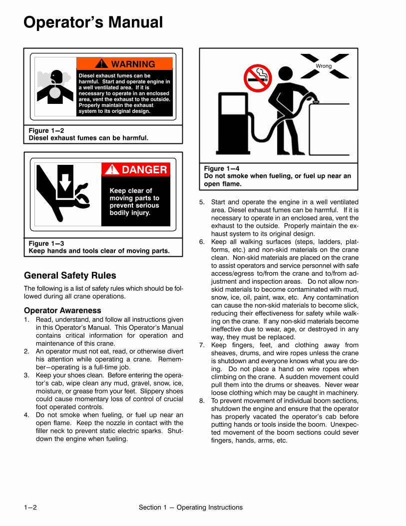
Figure 1-2Diesel exhaust fumes can be harmful.
Diesel exhaust fumes can beharmful. Start and operate engine ina well ventilated area. If it isnecessary to operate in an enclosedarea, vent the exhaust to the outside.Properly maintain the exhaustsystem to its original design.
Figure 1-3Keep hands and tools clear of moving parts.
Keep clear ofmoving parts toprevent seriousbodily injury.
General Safety Rules
The following is a list of safety rules which should be followed during all crane operations.
Operator Awareness1. Read, understand, and follow all instructions given
in this Operator's Manual. This Operator's Manualcontains critical information for operation andmaintenance of this crane.
2. An operator must not eat, read, or otherwise diverthis attention while operating a crane. Remember-operating is a full‐time job.
3. Keep your shoes clean. Before entering the operator's cab, wipe clean any mud, gravel, snow, ice,moisture, or grease from your feet. Slippery shoescould cause momentary loss of control of crucialfoot operated controls.
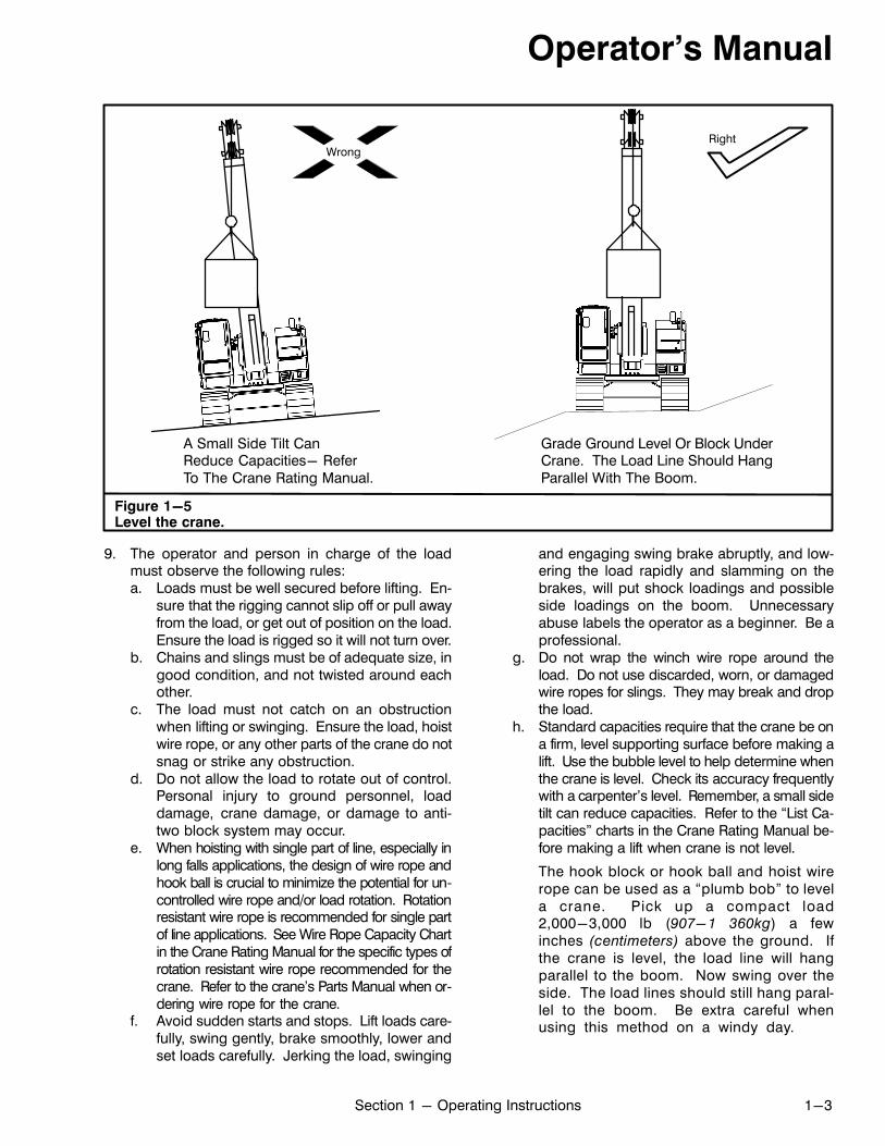
4. Do not smoke when fueling, or fuel up near anopen flame. Keep the nozzle in contact with thefiller neck to prevent static electric sparks. Shutdown the engine when fueling.
Wrong
Figure 1-4Do not smoke when fueling, or fuel up near an
open flame.
5. Start and operate the engine in a well ventilatedarea. Diesel exhaust fumes can be harmful. If it isnecessary to operate in an enclosed area, vent theexhaust to the outside. Properly maintain the exhaust system to its original design.
6. Keep all walking surfaces (steps, ladders, platforms, etc.) and non‐skid materials on the craneclean. Non‐skid materials are placed on the craneto assist operators and service personnel with safeaccess/egress to/from the crane and to/from adjustment and inspection areas. Do not allow non‐skid materials to become contaminated with mud,snow, ice, oil, paint, wax, etc. Any contaminationcan cause the non‐skid materials to become slick,reducing their effectiveness for safety while walking on the crane. If any non‐skid materials becomeineffective due to wear, age, or destroyed in anyway, they must be replaced.
7. Keep fingers, feet, and clothing away fromsheaves, drums, and wire ropes unless the craneis shutdown and everyone knows what you are doing. Do not place a hand on wire ropes whenclimbing on the crane. A sudden movement couldpull them into the drums or sheaves. Never wearloose clothing which may be caught in machinery.
8. To prevent movement of individual boom sections,shutdown the engine and ensure that the operatorhas properly vacated the operator's cab beforeputting hands or tools inside the boom. Unexpected movement of the boom sections could severfingers, hands, arms, etc.
Operator's Manual
1-3Section 1 - Operating Instructions
WrongRight
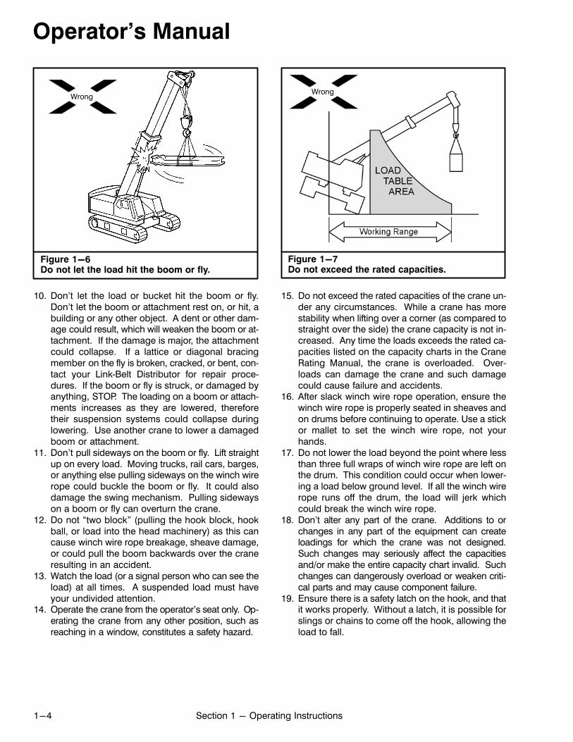
Figure 1-5Level the crane.
A Small Side Tilt CanReduce Capacities- ReferTo The Crane Rating Manual.
Grade Ground Level Or Block UnderCrane. The Load Line Should HangParallel With The Boom.
9. The operator and person in charge of the loadmust observe the following rules:a. Loads must be well secured before lifting. En
sure that the rigging cannot slip off or pull awayfrom the load, or get out of position on the load.Ensure the load is rigged so it will not turn over.
b. Chains and slings must be of adequate size, ingood condition, and not twisted around eachother.
c. The load must not catch on an obstructionwhen lifting or swinging. Ensure the load, hoistwire rope, or any other parts of the crane do notsnag or strike any obstruction.
d. Do not allow the load to rotate out of control.Personal injury to ground personnel, loaddamage, crane damage, or damage to anti‐two block system may occur.
e. When hoisting with single part of line, especially inlong falls applications, the design of wire rope andhook ball is crucial to minimize the potential for uncontrolled wire rope and/or load rotation. Rotationresistant wire rope is recommended for single partof line applications. See Wire Rope Capacity Chartin the Crane Rating Manual for the specific types ofrotation resistant wire rope recommended for thecrane. Refer to the crane's Parts Manual when ordering wire rope for the crane.
f. Avoid sudden starts and stops. Lift loads carefully, swing gently, brake smoothly, lower andset loads carefully. Jerking the load, swinging
and engaging swing brake abruptly, and lowering the load rapidly and slamming on thebrakes, will put shock loadings and possibleside loadings on the boom. Unnecessaryabuse labels the operator as a beginner. Be aprofessional.
g. Do not wrap the winch wire rope around theload. Do not use discarded, worn, or damagedwire ropes for slings. They may break and dropthe load.
h. Standard capacities require that the crane be ona firm, level supporting surface before making alift. Use the bubble level to help determine whenthe crane is level. Check its accuracy frequentlywith a carpenter's level. Remember, a small sidetilt can reduce capacities. Refer to the “List Capacities” charts in the Crane Rating Manual before making a lift when crane is not level.
The hook block or hook ball and hoist wirerope can be used as a “plumb bob” to levela crane. Pick up a compact load2,000-3,000 lb (907-1 360kg) a fewinches (centimeters) above the ground. Ifthe crane is level, the load line will hangparallel to the boom. Now swing over theside. The load lines should still hang parallel to the boom. Be extra careful whenusing this method on a windy day.
Operator's Manual
1-4 Section 1 - Operating Instructions
Wrong
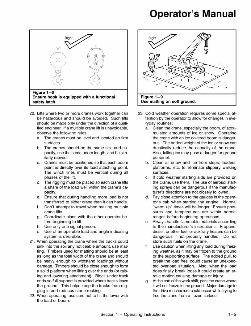
Figure 1-6Do not let the load hit the boom or fly.
10. Don't let the load or bucket hit the boom or fly.Don't let the boom or attachment rest on, or hit, abuilding or any other object. A dent or other damage could result, which will weaken the boom or attachment. If the damage is major, the attachmentcould collapse. If a lattice or diagonal bracingmember on the fly is broken, cracked, or bent, contact your Link‐Belt Distributor for repair procedures. If the boom or fly is struck, or damaged byanything, STOP. The loading on a boom or attachments increases as they are lowered, thereforetheir suspension systems could collapse duringlowering. Use another crane to lower a damagedboom or attachment.
11. Don't pull sideways on the boom or fly. Lift straightup on every load. Moving trucks, rail cars, barges,or anything else pulling sideways on the winch wirerope could buckle the boom or fly. It could alsodamage the swing mechanism. Pulling sidewayson a boom or fly can overturn the crane.
12. Do not “two block” (pulling the hook block, hookball, or load into the head machinery) as this cancause winch wire rope breakage, sheave damage,or could pull the boom backwards over the craneresulting in an accident.
13. Watch the load (or a signal person who can see theload) at all times. A suspended load must haveyour undivided attention.
14. Operate the crane from the operator's seat only. Operating the crane from any other position, such asreaching in a window, constitutes a safety hazard.
Figure 1-7Do not exceed the rated capacities.
Wrong
15. Do not exceed the rated capacities of the crane under any circumstances. While a crane has morestability when lifting over a corner (as compared tostraight over the side) the crane capacity is not increased. Any time the loads exceeds the rated capacities listed on the capacity charts in the CraneRating Manual, the crane is overloaded. Overloads can damage the crane and such damagecould cause failure and accidents.
16. After slack winch wire rope operation, ensure thewinch wire rope is properly seated in sheaves andon drums before continuing to operate. Use a stickor mallet to set the winch wire rope, not yourhands.
17. Do not lower the load beyond the point where lessthan three full wraps of winch wire rope are left onthe drum. This condition could occur when lowering a load below ground level. If all the winch wirerope runs off the drum, the load will jerk whichcould break the winch wire rope.
18. Don't alter any part of the crane. Additions to orchanges in any part of the equipment can createloadings for which the crane was not designed.Such changes may seriously affect the capacitiesand/or make the entire capacity chart invalid. Suchchanges can dangerously overload or weaken critical parts and may cause component failure.
19. Ensure there is a safety latch on the hook, and thatit works properly. Without a latch, it is possible forslings or chains to come off the hook, allowing theload to fall.
Operator's Manual
1-5Section 1 - Operating Instructions
Figure 1-8Ensure hook is equipped with a functional
safety latch.
Right
20. Lifts where two or more cranes work together canbe hazardous and should be avoided. Such liftsshould be made only under the direction of a qualified engineer. If a multiple crane lift is unavoidable,observe the following rules:a. The cranes must be level and located on firm
surfaces.b. The cranes should be the same size and ca
pacity, use the same boom length, and be similarly reeved.
c. Cranes must be positioned so that each boompoint is directly over its load attaching point.The winch lines must be vertical during allphases of the lift.
d. The rigging must be placed so each crane liftsa share of the load well within the crane's capacity.
e. Ensure that during handling more load is nottransferred to either crane than it can handle.
f. Don't attempt to travel when making multiplecrane lifts.
g. Coordinate plans with the other operator before beginning to lift.
h. Use only one signal person.i. Use of an operable load and angle indicating
system is desirable.21. When operating the crane where the tracks could
sink into the soil any noticeable amount, use matting. Timbers used for matting should be at leastas long as the total width of the crane and shouldbe heavy enough to withstand loadings withoutdamage. Timbers should be close enough to forma solid platform when lifting over the ends (or raising and lowering attachment). Block under trackends so full support is provided where tracks leavethe ground. This helps keep the tracks from digging in and reduces crane rocking.
22. When operating, use care not to hit the lower withthe load or boom.
Figure 1-9Use matting on soft ground.
Right
23. Cold weather operation requires some special attention by the operator to allow for changes in everyday routines:a. Clean the crane, especially the boom, of accu
mulated amounts of ice or snow. Operatingthe crane with an ice covered boom is dangerous. The added weight of the ice or snow candrastically reduce the capacity of the crane.Also, falling ice may pose a danger for groundpersonel.
b. Clean all snow and ice from steps, ladders,platforms, etc. to eliminate slippery walkingsurfaces.
c. If cold weather starting aids are provided onthe crane, use them. The use of aerosol starting sprays can be dangerous if the manufacturer's directions are not closely followed.
d. Pay close attention to the gauges in the operator's cab when starting the engine. Normal“warm up” times will be longer. Ensure pressures and temperatures are within normalranges before beginning operations.
e. Always handle flammable materials accordingto the manufacturer's instructions. Propane,diesel, or other fuel for auxiliary heaters can bedangerous if not properly handled. Do notstore such fuels on the crane.
f. Use caution when lifting any load during freezing weather, as it may be frozen to the groundor the supporting surface. The added pull, tobreak the load free, could cause an unexpected overload situation. Also, when the loaddoes finally break loose it could create an erratic motion causing damage or injury.
g. At the end of the work shift, park the crane whereit will not freeze to the ground. Major damage tothe drive mechanism could occur while trying tofree the crane from a frozen surface.
Operator's Manual
1-6 Section 1 - Operating Instructions
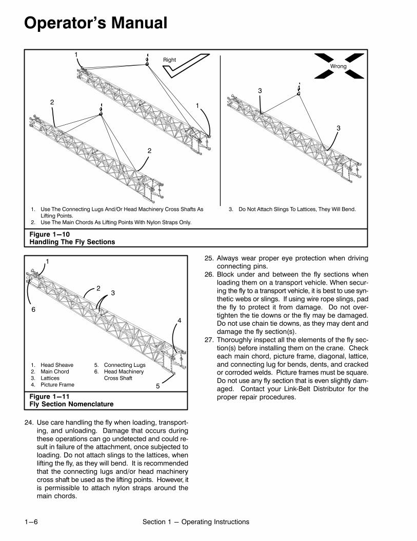
Figure 1-10Handling The Fly Sections
RightWrong
1. Use The Connecting Lugs And/Or Head Machinery Cross Shafts AsLifting Points.
2. Use The Main Chords As Lifting Points With Nylon Straps Only.
3. Do Not Attach Slings To Lattices, They Will Bend.
3
1
12
2
3
Figure 1-11Fly Section Nomenclature
1. Head Sheave2. Main Chord3. Lattices4. Picture Frame
5. Connecting Lugs6. Head Machinery
Cross Shaft
1
23
4
5
6
24. Use care handling the fly when loading, transporting, and unloading. Damage that occurs duringthese operations can go undetected and could result in failure of the attachment, once subjected toloading. Do not attach slings to the lattices, whenlifting the fly, as they will bend. It is recommendedthat the connecting lugs and/or head machinerycross shaft be used as the lifting points. However, itis permissible to attach nylon straps around themain chords.
25. Always wear proper eye protection when drivingconnecting pins.
26. Block under and between the fly sections whenloading them on a transport vehicle. When securing the fly to a transport vehicle, it is best to use synthetic webs or slings. If using wire rope slings, padthe fly to protect it from damage. Do not overtighten the tie downs or the fly may be damaged.Do not use chain tie downs, as they may dent anddamage the fly section(s).
27. Thoroughly inspect all the elements of the fly section(s) before installing them on the crane. Checkeach main chord, picture frame, diagonal, lattice,and connecting lug for bends, dents, and crackedor corroded welds. Picture frames must be square.Do not use any fly section that is even slightly damaged. Contact your Link‐Belt Distributor for theproper repair procedures.
Operator's Manual
1-7Section 1 - Operating Instructions
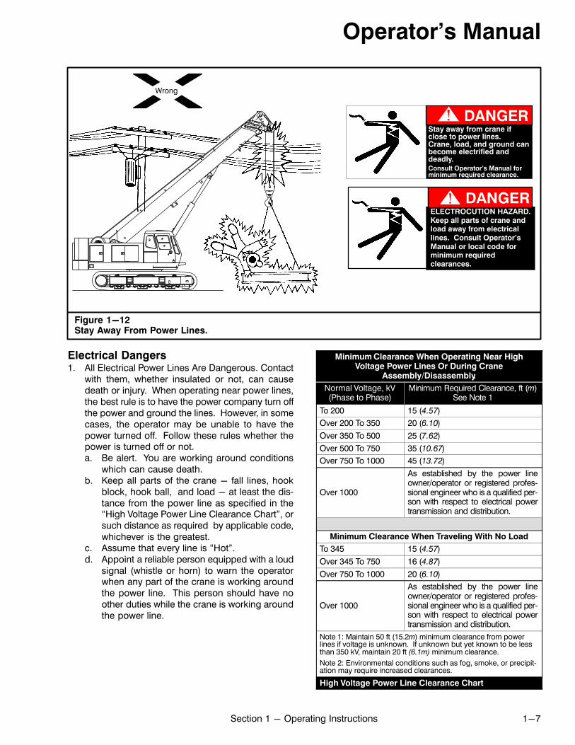
Figure 1-12Stay Away From Power Lines.
Wrong
ELECTROCUTION HAZARD.Keep all parts of crane andload away from electricallines. Consult Operator'sManual or local code forminimum requiredclearances.
Stay away from crane ifclose to power lines.Crane, load, and ground canbecome electrified anddeadly.Consult Operator's Manual forminimum required clearance.
Electrical Dangers1. All Electrical Power Lines Are Dangerous. Contact
with them, whether insulated or not, can causedeath or injury. When operating near power lines,the best rule is to have the power company turn offthe power and ground the lines. However, in somecases, the operator may be unable to have thepower turned off. Follow these rules whether thepower is turned off or not.a. Be alert. You are working around conditions
which can cause death.b. Keep all parts of the crane - fall lines, hook
block, hook ball, and load - at least the distance from the power line as specified in the“High Voltage Power Line Clearance Chart”, orsuch distance as required by applicable code,whichever is the greatest.
c. Assume that every line is “Hot”.d. Appoint a reliable person equipped with a loud
signal (whistle or horn) to warn the operatorwhen any part of the crane is working aroundthe power line. This person should have noother duties while the crane is working aroundthe power line.
Minimum Clearance When Operating Near HighVoltage Power Lines Or During Crane
Assembly/Disassembly.
Normal Voltage, kV(Phase to Phase)
Minimum Required Clearance, ft (m)See Note 1
To 200 15 (4.57)
Over 200 To 350 20 (6.10)
Over 350 To 500 25 (7.62)
Over 500 To 750 35 (10.67)
Over 750 To 1000 45 (13.72)
Over 1000
As established by the power lineowner/operator or registered professional engineer who is a qualified person with respect to electrical powertransmission and distribution.
Minimum Clearance When Traveling With No Load
To 345 15 (4.57)
Over 345 To 750 16 (4.87)
Over 750 To 1000 20 (6.10)
Over 1000
As established by the power lineowner/operator or registered professional engineer who is a qualified person with respect to electrical powertransmission and distribution.
Note 1: Maintain 50 ft (15.2m) minimum clearance from powerlines if voltage is unknown. If unknown but yet known to be lessthan 350 kV, maintain 20 ft (6.1m) minimum clearance.
Note 2: Environmental conditions such as fog, smoke, or precipitation may require increased clearances.
High Voltage Power Line Clearance Chart
Operator's Manual
1-8 Section 1 - Operating Instructions
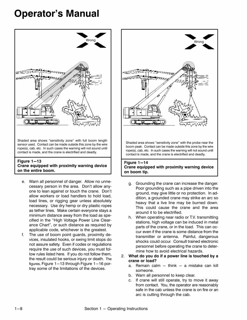
Figure 1-13Crane equipped with proximity warning device
on the entire boom.
Wrong
Shaded area shows “sensitivity zone” with full boom lengthsensor used. Contact can be made outside this zone by the wirerope(s), cab, etc. In such cases the warning will not sound untilcontact is made, and the crane is electrified and deadly.
e. Warn all personnel of danger. Allow no unnecessary person in the area. Don't allow anyone to lean against or touch the crane. Don'tallow workers or load handlers to hold load,load lines, or rigging gear unless absolutelynecessary. Use dry hemp or dry plastic ropesas tether lines. Make certain everyone stays aminimum distance away from the load as specified in the “High Voltage Power Line Clearance Chart”, or such distance as required byapplicable code, whichever is the greatest.
f. The use of boom point guards, proximity devices, insulated hooks, or swing limit stops donot assure safety. Even if codes or regulationsrequire the use of such devices, you must follow rules listed here. If you do not follow them,the result could be serious injury or death. The
figures, Figure 1-13 through Figure 1-16 portray some of the limitations of the devices.
Figure 1-14Crane equipped with proximity warning device
on boom tip.
Wrong
Shaded area shows “sensitivity zone” with the probe near theboom peak. Contact can be made outside this zone by the wirerope(s), cab, etc. In such cases the warning will not sound untilcontact is made, and the crane is electrified and deadly.
g. Grounding the crane can increase the danger.Poor grounding such as a pipe driven into theground, may give little or no protection. In addition, a grounded crane may strike an arc soheavy that a live line may be burned down.This could cause the crane and the areaaround it to be electrified.
h. When operating near radio or T.V. transmittingstations, high voltage can be induced in metalparts of the crane, or in the load. This can occur even if the crane is some distance from thetransmitter or antenna. Painful, dangerousshocks could occur. Consult trained electronicpersonnel before operating the crane to determine how to avoid electrical hazards.
2. What do you do if a power line is touched by acrane or load?
a. Remain calm - think - a mistake can killsomeone.
b. Warn all personnel to keep clear.c. If crane will still operate, try to move it away
from contact. You, the operator are reasonablysafe in the cab unless the crane is on fire or anarc is cutting through the cab.
Operator's Manual
1-9Section 1 - Operating Instructions
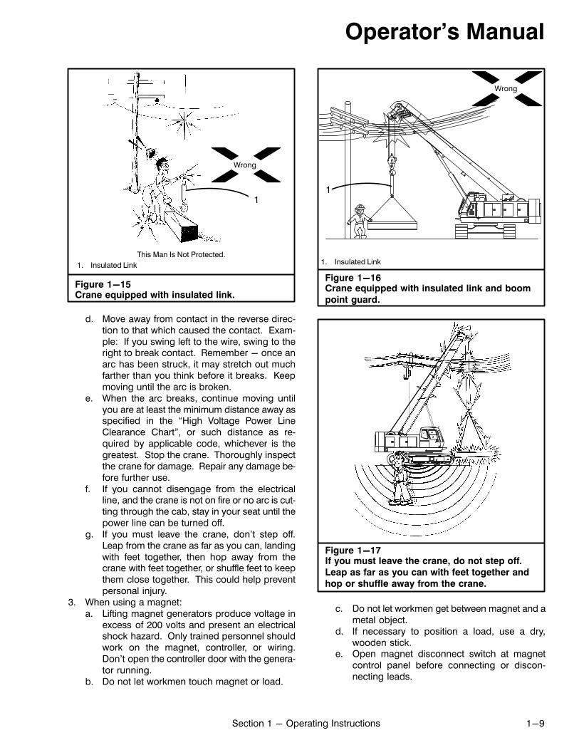
Figure 1-15Crane equipped with insulated link.
1
1. Insulated Link
This Man Is Not Protected.
Wrong
d. Move away from contact in the reverse direction to that which caused the contact. Example: If you swing left to the wire, swing to theright to break contact. Remember - once anarc has been struck, it may stretch out muchfarther than you think before it breaks. Keepmoving until the arc is broken.
e. When the arc breaks, continue moving untilyou are at least the minimum distance away asspecified in the “High Voltage Power LineClearance Chart”, or such distance as required by applicable code, whichever is thegreatest. Stop the crane. Thoroughly inspectthe crane for damage. Repair any damage before further use.
f. If you cannot disengage from the electricalline, and the crane is not on fire or no arc is cutting through the cab, stay in your seat until thepower line can be turned off.
g. If you must leave the crane, don't step off.Leap from the crane as far as you can, landingwith feet together, then hop away from thecrane with feet together, or shuffle feet to keepthem close together. This could help preventpersonal injury.
3. When using a magnet:a. Lifting magnet generators produce voltage in
excess of 200 volts and present an electricalshock hazard. Only trained personnel shouldwork on the magnet, controller, or wiring.Don't open the controller door with the generator running.
b. Do not let workmen touch magnet or load.
Figure 1-16Crane equipped with insulated link and boom
point guard.
1
1. Insulated Link
Wrong
Figure 1-17If you must leave the crane, do not step off.
Leap as far as you can with feet together and
hop or shuffle away from the crane.
c. Do not let workmen get between magnet and ametal object.
d. If necessary to position a load, use a dry,wooden stick.
e. Open magnet disconnect switch at magnetcontrol panel before connecting or disconnecting leads.
Operator's Manual
1-10 Section 1 - Operating Instructions
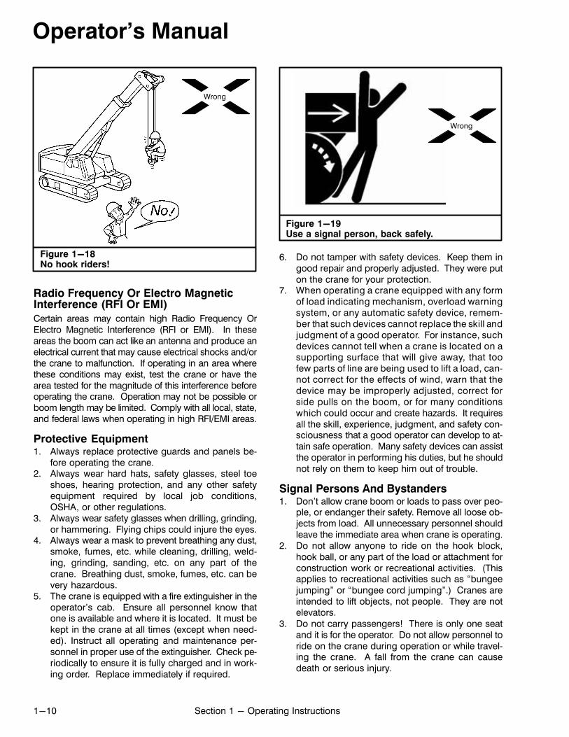
Figure 1-18No hook riders!
Wrong
Radio Frequency Or Electro MagneticInterference (RFI Or EMI)
Certain areas may contain high Radio Frequency OrElectro Magnetic Interference (RFI or EMI). In theseareas the boom can act like an antenna and produce anelectrical current that may cause electrical shocks and/orthe crane to malfunction. If operating in an area wherethese conditions may exist, test the crane or have thearea tested for the magnitude of this interference beforeoperating the crane. Operation may not be possible orboom length may be limited. Comply with all local, state,and federal laws when operating in high RFI/EMI areas.
Protective Equipment1. Always replace protective guards and panels be
fore operating the crane.2. Always wear hard hats, safety glasses, steel toe
shoes, hearing protection, and any other safetyequipment required by local job conditions,OSHA, or other regulations.
3. Always wear safety glasses when drilling, grinding,or hammering. Flying chips could injure the eyes.
4. Always wear a mask to prevent breathing any dust,smoke, fumes, etc. while cleaning, drilling, welding, grinding, sanding, etc. on any part of thecrane. Breathing dust, smoke, fumes, etc. can bevery hazardous.
5. The crane is equipped with a fire extinguisher in theoperator's cab. Ensure all personnel know thatone is available and where it is located. It must bekept in the crane at all times (except when needed). Instruct all operating and maintenance personnel in proper use of the extinguisher. Check periodically to ensure it is fully charged and in working order. Replace immediately if required.
Figure 1-19Use a signal person, back safely.
Wrong
6. Do not tamper with safety devices. Keep them ingood repair and properly adjusted. They were puton the crane for your protection.
7. When operating a crane equipped with any formof load indicating mechanism, overload warningsystem, or any automatic safety device, remember that such devices cannot replace the skill andjudgment of a good operator. For instance, suchdevices cannot tell when a crane is located on asupporting surface that will give away, that toofew parts of line are being used to lift a load, cannot correct for the effects of wind, warn that thedevice may be improperly adjusted, correct forside pulls on the boom, or for many conditionswhich could occur and create hazards. It requiresall the skill, experience, judgment, and safety consciousness that a good operator can develop to attain safe operation. Many safety devices can assistthe operator in performing his duties, but he shouldnot rely on them to keep him out of trouble.
Signal Persons And Bystanders1. Don't allow crane boom or loads to pass over peo
ple, or endanger their safety. Remove all loose objects from load. All unnecessary personnel shouldleave the immediate area when crane is operating.
2. Do not allow anyone to ride on the hook block,hook ball, or any part of the load or attachment forconstruction work or recreational activities. (Thisapplies to recreational activities such as “bungeejumping” or “bungee cord jumping”.) Cranes areintended to lift objects, not people. They are notelevators.
3. Do not carry passengers! There is only one seatand it is for the operator. Do not allow personnel toride on the crane during operation or while traveling the crane. A fall from the crane can causedeath or serious injury.
Operator's Manual
1-11Section 1 - Operating Instructions
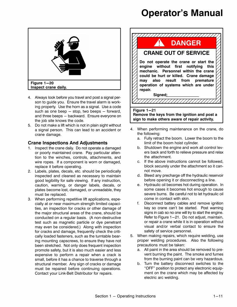
Figure 1-20Inspect crane daily.
4. Always look before you travel and post a signal person to guide you. Ensure the travel alarm is working properly. Use the horn as a signal. Use a codesuch as one beep - stop, two beeps - forward,and three beeps - backward. Ensure everyone onthe job site knows the code.
5. Do not make a lift which is not in plain sight withouta signal person. This can lead to an accident orcrane damage.
Crane Inspections And Adjustments1. Inspect the crane daily. Do not operate a damaged
or poorly maintained crane. Pay particular attention to the winches, controls, attachments, andwire ropes. If a component is worn or damaged,replace it before operating.
2. Labels, plates, decals, etc. should be periodicallyinspected and cleaned as necessary to maintaingood legibility for safe viewing. If any instruction,caution, warning, or danger labels, decals, orplates become lost, damaged, or unreadable, theymust be replaced.
3. When performing repetitive lift applications, especially at or near maximum strength limited capacities, an inspection for cracks or other damage ofthe major structural areas of the crane, should beconducted on a regular basis. (A non‐destructivetest such as magnetic particle or dye penetrantmay even be considered.) Along with inspectionfor cracks and damage, frequently check the critically loaded fasteners, such as the turntable bearing mounting capscrews, to ensure they have notbeen stretched. Not only does frequent inspectionpromote safety, but it is also much easier and lessexpensive to perform a repair when a crack issmall, before it has a chance to traverse through astructural member. Any sign of cracks or damagemust be repaired before continuing operations.Contact your Link‐Belt Distributor for repairs.
Figure 1-21Remove the keys from the ignition and post a
sign to make others aware of repair activity.
ÉÉÉÉÉÉÉÉÉÉÉÉÉÉÉÉÉÉÉÉÉÉÉÉÉÉÉÉÉÉÉÉÉÉÉÉÉÉÉÉÉÉÉÉÉÉÉÉÉÉÉÉÉÉÉÉÉÉÉÉÉÉÉÉÉÉÉÉÉÉÉÉÉÉÉÉÉÉÉÉÉÉÉÉÉÉÉÉÉÉÉÉÉÉÉÉÉÉÉÉÉÉÉÉÉÉÉÉÉÉÉÉÉÉÉÉÉÉÉÉÉÉÉÉÉÉÉÉÉÉÉÉÉÉÉÉÉÉÉÉÉÉÉÉÉÉÉÉÉÉÉÉÉÉÉÉÉÉÉÉÉÉÉÉÉÉÉÉÉÉÉÉÉÉÉÉÉÉÉÉÉÉÉÉÉÉÉÉÉÉÉÉÉÉÉÉÉÉÉÉÉÉÉÉÉÉÉÉ
CRANE OUT OF SERVICE
Signed:
Do not operate the crane or start theengine without first notifying this
mechanic. Personnel within the crane
could be hurt or killed. Crane damage
may also result from premature
operation of systems which are under
repair.
DANGER
4. When performing maintenance on the crane, dothe following:a. Fully retract the boom. Lower the boom to the
limit of the boom hoist cylinder.b. Shutdown the engine and work all control lev
ers back and forth to relieve pressure and relaxthe attachment.
c. If the above instructions cannot be followed,block securely under the attachment so it cannot move.
d. Bleed any precharge off the hydraulic reservoirbefore opening it or disconnecting a line.
e. Hydraulic oil becomes hot during operation. Insome cases it becomes hot enough to causesevere burns. Be careful not to let hydraulic oilcome in contact with skin.
f. Disconnect battery cables and remove ignitionkey so crane can't be started. Post warningsigns in cab so no one will try to start the engine.Refer to Figure 1-21. Do not adjust, maintain,or repair a crane while it is in operation withoutvisual and/or verbal contact to ensure thesafety of service personnel.
5. When making repairs, which require welding, useproper welding procedures. Also the followingprecautions must be taken:a. All paint in the area should be removed to pre
vent burning the paint. The smoke and fumesfrom the burning paint can be very hazardous.
b. Turn the battery disconnect switches to the“OFF” position to protect any electronic equipment on the crane which may be affected byelectric arc welding.
Operator's Manual
1-12 Section 1 - Operating Instructions
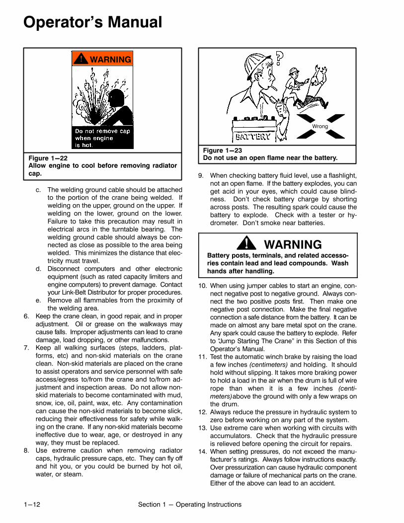
Figure 1-22Allow engine to cool before removing radiator
cap.
c. The welding ground cable should be attachedto the portion of the crane being welded. Ifwelding on the upper, ground on the upper. Ifwelding on the lower, ground on the lower.Failure to take this precaution may result inelectrical arcs in the turntable bearing. Thewelding ground cable should always be connected as close as possible to the area beingwelded. This minimizes the distance that electricity must travel.
d. Disconnect computers and other electronicequipment (such as rated capacity limiters andengine computers) to prevent damage. Contactyour Link‐Belt Distributor for proper procedures.
e. Remove all flammables from the proximity ofthe welding area.
6. Keep the crane clean, in good repair, and in properadjustment. Oil or grease on the walkways maycause falls. Improper adjustments can lead to cranedamage, load dropping, or other malfunctions.
7. Keep all walking surfaces (steps, ladders, platforms, etc) and non‐skid materials on the craneclean. Non‐skid materials are placed on the craneto assist operators and service personnel with safeaccess/egress to/from the crane and to/from adjustment and inspection areas. Do not allow non‐skid materials to become contaminated with mud,snow, ice, oil, paint, wax, etc. Any contaminationcan cause the non‐skid materials to become slick,reducing their effectiveness for safety while walking on the crane. If any non‐skid materials becomeineffective due to wear, age, or destroyed in anyway, they must be replaced.
8. Use extreme caution when removing radiatorcaps, hydraulic pressure caps, etc. They can fly offand hit you, or you could be burned by hot oil,water, or steam.
Figure 1-23Do not use an open flame near the battery.
Wrong
9. When checking battery fluid level, use a flashlight,not an open flame. If the battery explodes, you canget acid in your eyes, which could cause blindness. Don't check battery charge by shortingacross posts. The resulting spark could cause thebattery to explode. Check with a tester or hydrometer. Don't smoke near batteries.
WARNINGBattery posts, terminals, and related accessories contain lead and lead compounds. Wash
hands after handling.
10. When using jumper cables to start an engine, connect negative post to negative ground. Always connect the two positive posts first. Then make onenegative post connection. Make the final negativeconnection a safe distance from the battery. It can bemade on almost any bare metal spot on the crane.Any spark could cause the battery to explode. Referto “Jump Starting The Crane” in this Section of thisOperator's Manual.
11. Test the automatic winch brake by raising the loada few inches (centimeters) and holding. It shouldhold without slipping. It takes more braking powerto hold a load in the air when the drum is full of wirerope than when it is a few inches (centi
meters)above the ground with only a few wraps onthe drum.
12. Always reduce the pressure in hydraulic system tozero before working on any part of the system.
13. Use extreme care when working with circuits withaccumulators. Check that the hydraulic pressureis relieved before opening the circuit for repairs.
14. When setting pressures, do not exceed the manufacturer's ratings. Always follow instructions exactly.Over pressurization can cause hydraulic componentdamage or failure of mechanical parts on the crane.Either of the above can lead to an accident.
Operator's Manual
1-13Section 1 - Operating Instructions
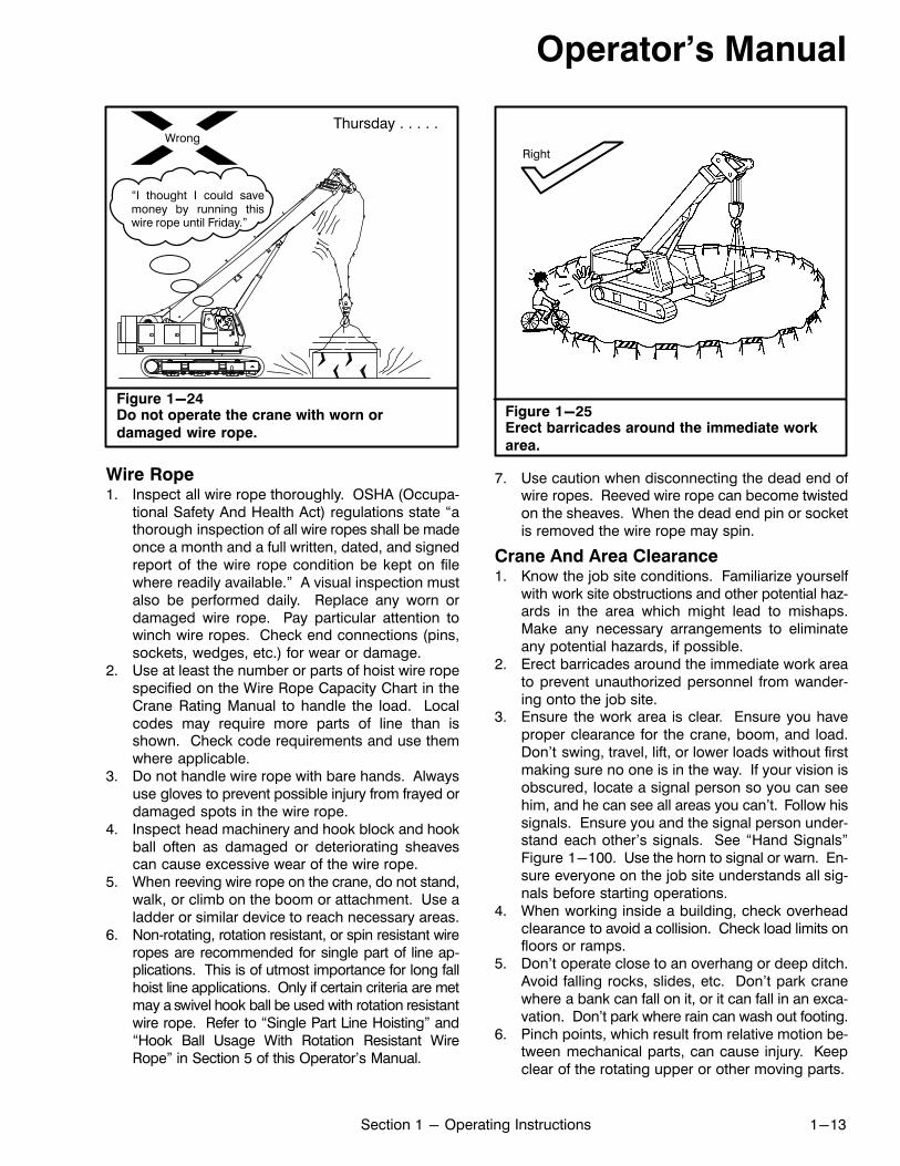
Figure 1-24Do not operate the crane with worn or
damaged wire rope.
Thursday . . . . .Wrong
“I thought I could savemoney by running thiswire rope until Friday.”
Wire Rope1. Inspect all wire rope thoroughly. OSHA (Occupa
tional Safety And Health Act) regulations state “athorough inspection of all wire ropes shall be madeonce a month and a full written, dated, and signedreport of the wire rope condition be kept on filewhere readily available.” A visual inspection mustalso be performed daily. Replace any worn ordamaged wire rope. Pay particular attention towinch wire ropes. Check end connections (pins,sockets, wedges, etc.) for wear or damage.
2. Use at least the number or parts of hoist wire ropespecified on the Wire Rope Capacity Chart in theCrane Rating Manual to handle the load. Localcodes may require more parts of line than isshown. Check code requirements and use themwhere applicable.
3. Do not handle wire rope with bare hands. Alwaysuse gloves to prevent possible injury from frayed ordamaged spots in the wire rope.
4. Inspect head machinery and hook block and hookball often as damaged or deteriorating sheavescan cause excessive wear of the wire rope.
5. When reeving wire rope on the crane, do not stand,walk, or climb on the boom or attachment. Use aladder or similar device to reach necessary areas.
6. Non‐rotating, rotation resistant, or spin resistant wireropes are recommended for single part of line applications. This is of utmost importance for long fallhoist line applications. Only if certain criteria are metmay a swivel hook ball be used with rotation resistantwire rope. Refer to “Single Part Line Hoisting” and“Hook Ball Usage With Rotation Resistant WireRope” in Section 5 of this Operator's Manual.
Figure 1-25Erect barricades around the immediate work
area.
Right
7. Use caution when disconnecting the dead end ofwire ropes. Reeved wire rope can become twistedon the sheaves. When the dead end pin or socketis removed the wire rope may spin.
Crane And Area Clearance1. Know the job site conditions. Familiarize yourself
with work site obstructions and other potential hazards in the area which might lead to mishaps.Make any necessary arrangements to eliminateany potential hazards, if possible.
2. Erect barricades around the immediate work areato prevent unauthorized personnel from wandering onto the job site.
3. Ensure the work area is clear. Ensure you haveproper clearance for the crane, boom, and load.Don't swing, travel, lift, or lower loads without firstmaking sure no one is in the way. If your vision isobscured, locate a signal person so you can seehim, and he can see all areas you can't. Follow hissignals. Ensure you and the signal person understand each other's signals. See “Hand Signals”Figure 1-100. Use the horn to signal or warn. Ensure everyone on the job site understands all signals before starting operations.
4. When working inside a building, check overheadclearance to avoid a collision. Check load limits onfloors or ramps.
5. Don't operate close to an overhang or deep ditch.Avoid falling rocks, slides, etc. Don't park cranewhere a bank can fall on it, or it can fall in an excavation. Don't park where rain can wash out footing.
6. Pinch points, which result from relative motion between mechanical parts, can cause injury. Keepclear of the rotating upper or other moving parts.
Operator's Manual
1-14 Section 1 - Operating Instructions
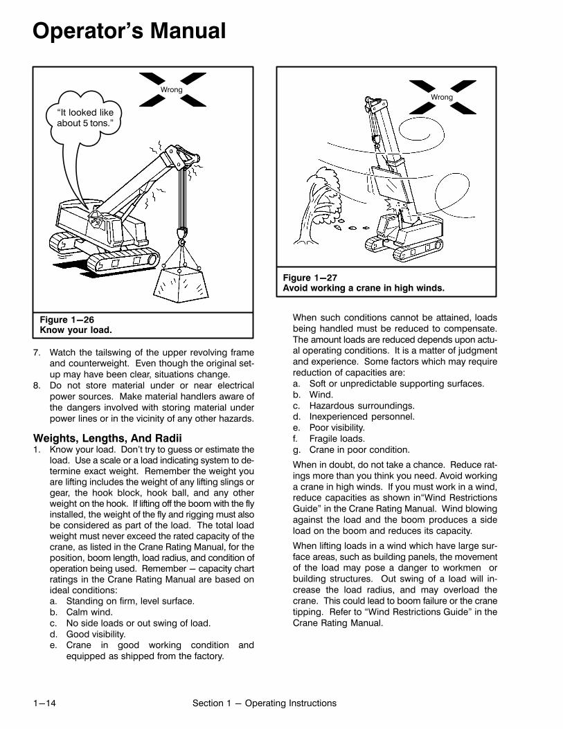
Figure 1-26Know your load.
Wrong
“It looked likeabout 5 tons.”
7. Watch the tailswing of the upper revolving frameand counterweight. Even though the original set‐up may have been clear, situations change.
8. Do not store material under or near electricalpower sources. Make material handlers aware ofthe dangers involved with storing material underpower lines or in the vicinity of any other hazards.
Weights, Lengths, And Radii1. Know your load. Don't try to guess or estimate the
load. Use a scale or a load indicating system to determine exact weight. Remember the weight youare lifting includes the weight of any lifting slings orgear, the hook block, hook ball, and any otherweight on the hook. If lifting off the boom with the flyinstalled, the weight of the fly and rigging must alsobe considered as part of the load. The total loadweight must never exceed the rated capacity of thecrane, as listed in the Crane Rating Manual, for theposition, boom length, load radius, and condition ofoperation being used. Remember - capacity chartratings in the Crane Rating Manual are based onideal conditions:a. Standing on firm, level surface.b. Calm wind.c. No side loads or out swing of load.d. Good visibility.e. Crane in good working condition and
equipped as shipped from the factory.
Wrong
Figure 1-27Avoid working a crane in high winds.
When such conditions cannot be attained, loadsbeing handled must be reduced to compensate.The amount loads are reduced depends upon actual operating conditions. It is a matter of judgmentand experience. Some factors which may requirereduction of capacities are:a. Soft or unpredictable supporting surfaces.b. Wind.c. Hazardous surroundings.d. Inexperienced personnel.e. Poor visibility.f. Fragile loads.g. Crane in poor condition.
When in doubt, do not take a chance. Reduce ratings more than you think you need. Avoid workinga crane in high winds. If you must work in a wind,reduce capacities as shown in“Wind RestrictionsGuide” in the Crane Rating Manual. Wind blowingagainst the load and the boom produces a sideload on the boom and reduces its capacity.
When lifting loads in a wind which have large surface areas, such as building panels, the movementof the load may pose a danger to workmen orbuilding structures. Out swing of a load will increase the load radius, and may overload thecrane. This could lead to boom failure or the cranetipping. Refer to “Wind Restrictions Guide” in theCrane Rating Manual.
Operator's Manual
1-15Section 1 - Operating Instructions
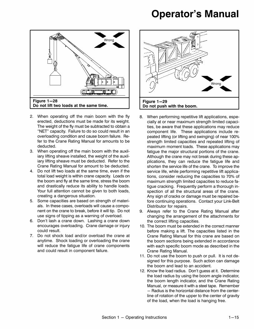
Figure 1-28Do not lift two loads at the same time.
Wrong
2. When operating off the main boom with the flyerected, deductions must be made for its weight.The weight of the fly must be subtracted to obtain a“NET” capacity. Failure to do so could result in anoverloading condition and cause boom failure. Refer to the Crane Rating Manual for amounts to bededucted.
3. When operating off the main boom with the auxiliary lifting sheave installed, the weight of the auxiliary lifting sheave must be deducted. Refer to theCrane Rating Manual for amount to be deducted.
4. Do not lift two loads at the same time, even if thetotal load weight is within crane capacity. Loads onthe boom and fly at the same time, stress the boomand drastically reduce its ability to handle loads.Your full attention cannot be given to both loads,creating a dangerous situation.
5. Some capacities are based on strength of materials. In these cases, overloads will cause a component on the crane to break, before it will tip. Do notuse signs of tipping as a warning of overload.
6. Don't lash a crane down. Lashing a crane downencourages overloading. Crane damage or injurycould result.
7. Do not shock load and/or overload the crane atanytime. Shock loading or overloading the cranewill reduce the fatigue life of crane componentsand could result in component failure.
Wrong
Figure 1-29Do not push with the boom.
8. When performing repetitive lift applications, especially at or near maximum strength limited capacities, be aware that these applications may reducecomponent life. These applications include repeated lifting (or lifting and swinging) of near 100%strength limited capacities and repeated lifting ofmaximum moment loads. These applications mayfatigue the major structural portions of the crane.Although the crane may not break during these applications, they can reduce the fatigue life andshorten the service life of the crane. To improve theservice life, while performing repetitive lift applications, consider reducing the capacities to 70% ofmaximum strength limited capacities to reduce fatigue cracking. Frequently perform a thorough inspection of all the structural areas of the crane.Any sign of cracks or damage must be repaired before continuing operations. Contact your Link‐BeltDistributor for repairs.
9. Always refer to the Crane Rating Manual afterchanging the arrangement of the attachments forthe correct lifting capacities.
10. The boom must be extended in the correct mannerbefore making a lift. The capacities listed in theCrane Rating Manual for this crane are based onthe boom sections being extended in accordancewith each specific boom mode as described in theCrane Rating Manual.
11. Do not use the boom to push or pull. It is not designed for this purpose. Such action can damagethe boom and lead to an accident.
12. Know the load radius. Don't guess at it. Determinethe load radius by using the boom angle indicator,the boom length indicator, and the Crane RatingManual, or measure it with a steel tape. Remember- Radius is the horizontal distance from the centerline of rotation of the upper to the center of gravityof the load, when the load is hanging free.
Operator's Manual
1-16 Section 1 - Operating Instructions
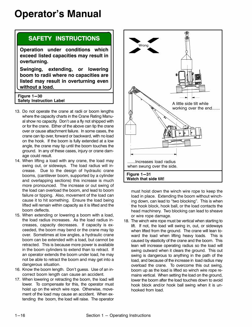
Figure 1-30Safety Instruction Label
Operation under conditions which
exceed listed capacities may result inoverturning.
Swinging, extending, or lowering
boom to radii where no capacities are
listed may result in overturning even
without a load.
13. Do not operate the crane at radii or boom lengthswhere the capacity charts in the Crane Rating Manual show no capacity. Don't use a fly not shipped withor for the crane. Either of the above can tip the craneover or cause attachment failure. In some cases, thecrane can tip over, forward or backward, with no loadon the hook. If the boom is fully extended at a lowangle, the crane may tip until the boom touches theground. In any of these cases, injury or crane damage could result.
14. When lifting a load with any crane, the load mayswing out, or sideways. The load radius will increase. Due to the design of hydraulic cranebooms, (cantilever boom, supported by a cylinderand overlapping sections) this increase is muchmore pronounced. The increase or out swing ofthe load can overload the boom, and lead to boomfailure or tipping. Also, movement of the load cancause it to hit something. Ensure the load beinglifted will remain within capacity as it is lifted and theboom deflects.
15. When extending or lowering a boom with a load,the load radius increases. As the load radius increases, capacity decreases. If capacity is exceeded, the boom may bend or the crane may tipover. Sometimes at low angles, a hydraulic craneboom can be extended with a load, but cannot beretracted. This is because more power is availablein the boom cylinders to extend than to retract. Ifan operator extends the boom under load, he maynot be able to retract the boom and may get into adangerous situation.
16. Know the boom length. Don't guess. Use of an incorrect boom length can cause an accident.
17. When lowering or retracting the boom, the load willlower. To compensate for this, the operator musthoist up on the winch wire rope. Otherwise, movement of the load may cause an accident. When extending the boom, the load will raise. The operator
Wrong
Figure 1-31Watch that side tilt!
A little side tilt whileworking over the end.......
.......Increases load radiuswhen swung over the side.
must hoist down the winch wire rope to keep theload in place. Extending the boom without winching down, can lead to “two blocking”. This is whenthe hook block, hook ball, or the load contacts thehead machinery. Two blocking can lead to sheaveor wire rope damage.
18. The winch wire rope must be vertical when starting tolift. If not, the load will swing in, out, or sidewayswhen lifted from the ground. The crane will lean toward the load when lifting heavy loads. This iscaused by elasticity of the crane and the boom. Thislean will increase operating radius so the load willswing outward when it clears the ground. This outswing is dangerous to anything in the path of theload, and because of the increase in load radius mayoverload the crane. To overcome this out swing,boom up as the load is lifted so winch wire rope remains vertical. When setting the load on the ground,lower the boom after the load touches down to avoidhook block and/or hook ball swing when it is unhooked from load.
Operator's Manual
1-17Section 1 - Operating Instructions
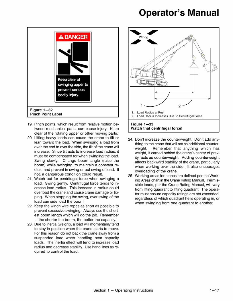
Figure 1-32Pinch Point Label
19. Pinch points, which result from relative motion between mechanical parts, can cause injury. Keepclear of the rotating upper or other moving parts.
20. Lifting heavy loads can cause the crane to tilt orlean toward the load. When swinging a load fromover the end to over the side, the tilt of the crane willincrease. Since tilt acts to increase load radius, itmust be compensated for when swinging the load.Swing slowly. Change boom angle (raise theboom) while swinging, to maintain a constant radius, and prevent in swing or out swing of load. Ifnot, a dangerous condition could result.
21. Watch out for centrifugal force when swinging aload. Swing gently. Centrifugal force tends to increase load radius. This increase in radius couldoverload the crane and cause crane damage or tipping. When stopping the swing, over swing of theload can side load the boom.
22. Keep the winch wire ropes as short as possible toprevent excessive swinging. Always use the shortest boom length which will do the job. Remember- the shorter the boom, the better the capacity.
23. Due to inertia (weight), a load will momentarily tendto stay in position when the crane starts to move.For this reason do not back the crane away from asuspended load when handling near capacityloads. The inertia effect will tend to increase loadradius and decrease stability. Use hand lines as required to control the load.
Figure 1-33Watch that centrifugal force!
Wrong
1. Load Radius at Rest2. Load Radius Increases Due To Centrifugal Force
1 2
24. Don't increase the counterweight. Don't add anything to the crane that will act as additional counterweight. Remember that anything which hasweight, if carried behind the crane's center of gravity, acts as counterweight. Adding counterweightaffects backward stability of the crane, particularlywhen working over the side. It also encouragesoverloading of the crane.
25. Working areas for cranes are defined per the Working Areas chart in the Crane Rating Manual. Permissible loads, per the Crane Rating Manual, will varyfrom lifting quadrant to lifting quadrant. The operator must ensure capacity ratings are not exceeded,regardless of which quadrant he is operating in, orwhen swinging from one quadrant to another.
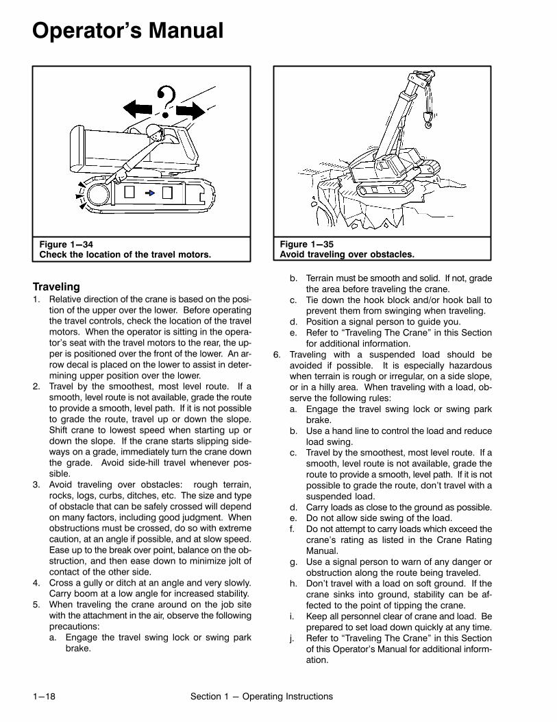
Operator's Manual
1-18 Section 1 - Operating Instructions
Figure 1-34Check the location of the travel motors.
Traveling1. Relative direction of the crane is based on the posi
tion of the upper over the lower. Before operatingthe travel controls, check the location of the travelmotors. When the operator is sitting in the operator's seat with the travel motors to the rear, the upper is positioned over the front of the lower. An arrow decal is placed on the lower to assist in determining upper position over the lower.
2. Travel by the smoothest, most level route. If asmooth, level route is not available, grade the routeto provide a smooth, level path. If it is not possibleto grade the route, travel up or down the slope.Shift crane to lowest speed when starting up ordown the slope. If the crane starts slipping sideways on a grade, immediately turn the crane downthe grade. Avoid side‐hill travel whenever possible.
3. Avoid traveling over obstacles: rough terrain,rocks, logs, curbs, ditches, etc. The size and typeof obstacle that can be safely crossed will dependon many factors, including good judgment. Whenobstructions must be crossed, do so with extremecaution, at an angle if possible, and at slow speed.Ease up to the break over point, balance on the obstruction, and then ease down to minimize jolt ofcontact of the other side.
4. Cross a gully or ditch at an angle and very slowly.Carry boom at a low angle for increased stability.
5. When traveling the crane around on the job sitewith the attachment in the air, observe the followingprecautions:a. Engage the travel swing lock or swing park
brake.
Figure 1-35Avoid traveling over obstacles.
b. Terrain must be smooth and solid. If not, gradethe area before traveling the crane.
c. Tie down the hook block and/or hook ball toprevent them from swinging when traveling.
d. Position a signal person to guide you.e. Refer to “Traveling The Crane” in this Section
for additional information.6. Traveling with a suspended load should be
avoided if possible. It is especially hazardouswhen terrain is rough or irregular, on a side slope,or in a hilly area. When traveling with a load, observe the following rules:a. Engage the travel swing lock or swing park
brake.b. Use a hand line to control the load and reduce
load swing.c. Travel by the smoothest, most level route. If a
smooth, level route is not available, grade theroute to provide a smooth, level path. If it is notpossible to grade the route, don't travel with asuspended load.
d. Carry loads as close to the ground as possible.e. Do not allow side swing of the load.f. Do not attempt to carry loads which exceed the
crane's rating as listed in the Crane RatingManual.
g. Use a signal person to warn of any danger orobstruction along the route being traveled.
h. Don't travel with a load on soft ground. If thecrane sinks into ground, stability can be affected to the point of tipping the crane.
i. Keep all personnel clear of crane and load. Beprepared to set load down quickly at any time.
j. Refer to “Traveling The Crane” in this Sectionof this Operator's Manual for additional information.
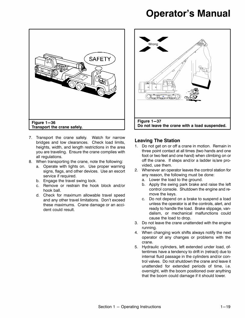
Operator's Manual
1-19Section 1 - Operating Instructions
Figure 1-36Transport the crane safely.
7. Transport the crane safely. Watch for narrowbridges and low clearances. Check load limits,heights, width, and length restrictions in the areayou are traveling. Ensure the crane complies withall regulations.
8. When transporting the crane, note the following:a. Operate with lights on. Use proper warning
signs, flags, and other devices. Use an escortservice if required.
b. Engage the travel swing lock.c. Remove or restrain the hook block and/or
hook ball.d. Check for maximum allowable travel speed
and any other travel limitations. Don't exceedthese maximums. Crane damage or an accident could result.
Wrong
Figure 1-37Do not leave the crane with a load suspended.
Leaving The Station1. Do not get on or off a crane in motion. Remain in
three point contact at all times (two hands and onefoot or two feet and one hand) when climbing on oroff the crane. If steps and/or a ladder is/are provided, use them.
2. Whenever an operator leaves the control station forany reason, the following must be done:a. Lower the load to the ground.b. Apply the swing park brake and raise the left
control console. Shutdown the engine and remove the keys.
c. Do not depend on a brake to suspend a loadunless the operator is at the controls, alert, andready to handle the load. Brake slippage, vandalism, or mechanical malfunctions couldcause the load to drop.
3. Do not leave the crane unattended with the enginerunning.
4. When changing work shifts always notify the nextoperator of any changes or problems with thecrane.
5. Hydraulic cylinders, left extended under load, oftentimes have a tendency to drift in (retract) due tointernal fluid passage in the cylinders and/or control valves. Do not shutdown the crane and leave itunattended for extended periods of time, i.e.overnight, with the boom positioned over anythingthat the boom could damage if it should lower.
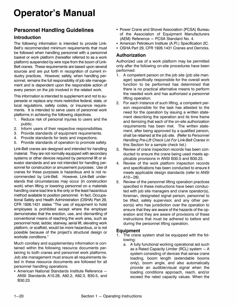
Operator's Manual
1-20 Section 1 - Operating Instructions
Personnel Handling Guidelines
Introduction
The following information is intended to provide Link‐Belt's recommended minimum requirements that mustbe followed when handling personnel with a personnelbasket or work platform (hereafter referred to as a workplatform) suspended by wire rope from the boom of Link‐Belt cranes. These requirements are based upon severalsources and are put forth in recognition of current industry practices. However, safety, when handling personnel, remains the full responsibility of job site management and is dependent upon the responsible action ofevery person on the job involved in the related work.
This information is intended to supplement and not to supersede or replace any more restrictive federal, state, orlocal regulations, safety codes, or insurance requirements. It is intended to serve users of personnel workplatforms in achieving the following objectives.1. Reduce risk of personal injuries to users and the
public.2. Inform users of their respective responsibilities.3. Provide standards of equipment requirements.4. Provide standards for tests and inspections.5. Provide standards of operation to promote safety.
Link‐Belt cranes are designed and intended for handlingmaterial. They are not normally equipped with secondarysystems or other devices required by personnel lift or elevator standards and are not intended for handling personnel for construction or amusement purposes. Use ofcranes for these purposes is hazardous and is not recommended by Link‐Belt. However, Link‐Belt understands that circumstances may occur (in constructionwork) when lifting or lowering personnel on a materialshandling crane load line is the only or the least hazardousmethod available to position personnel. In fact, Occupational Safety and Health Administration (OSHA) Part 29,CFR 1926.1431 states “The use of equipment to hoistemployees is prohibited except where the employerdemonstrates that the erection, use, and dismantling ofconventional means of reaching the work area, such aspersonnel hoist, ladder, stairway, aerial lift, elevating workplatform, or scaffold, would be more hazardous, or is notpossible because of the project's structural design orworksite conditions.”
Much corollary and supplementary information is contained within the following resource documents pertaining to both cranes and personnel work platforms.Job site management must ensure all requirements listed in these resource documents are followed for allpersonnel handling operations.� American National Standards Institute Reference -
ANSI Standards A10.28, A92.2, A92.3, B30.5, andB30.23.
� Power Crane and Shovel Association (PCSA) Bureauof the Association of Equipment Manufacturers(AEM) Reference - PCSA Standard No. 4.
� American Petroleum Institute (A.P.I.) Specification 2C.� OSHA Part 29, CFR 1926.1431 Cranes and Derricks.
Authorization
Authorized use of a work platform may be permittedonly after the following on‐site procedures have beenperformed:1. A competent person on the job site (job site man
ager) specifically responsible for the overall workfunction to be performed has determined thatthere is no practical alternative means to performthe needed work and has authorized a personnellifting operation.
2. For each instance of such lifting, a competent person responsible for the task has attested to theneed for the operation by issuing a written statement describing the operation and its time frameand itemizing that each of the on‐site authorizationrequirements has been met. The written statement, after being approved by a qualified person,shall be retained at the job site. (Refer to Personnel
Handling Pre‐Lift Check List For Link‐Belt Cranes inthis Section for a sample check list.)
3. Review of crane inspection records has been conducted to ensure the crane being used meets applicable provisions in ANSI B30.5 and B30.23.
4. Review of the work platform inspection recordsand specifications has been conducted to ensure itmeets applicable design standards (refer to ANSIA10-28).
5. Review of the personnel lifting operation practicesspecified in these instructions have been conducted with job site managers and crane operator(s),foreman, designated signal person, personnel tobe lifted, safety supervisor, and any other person(s) who has jurisdiction over the operation toensure that they are aware of the hazards of the operation and they are aware of provisions of theseinstructions that must be adhered to before andduring the personnel lifting operation.
Equipment1. The crane system shall be equipped with the fol
lowing:a. A fully functional working operational aid such
as a Rated Capacity Limiter (RCL) system - Asystem consisting of devices that sense craneloading, boom length (extendable boomsonly), boom angle, and also automaticallyprovide an audible/visual signal when theloading conditions approach, reach, and/orexceed the rated capacity values. When the

Operator's Manual
1-21Section 1 - Operating Instructions
Actual Load exceeds the Rated Capacity, thesystem supplies a signal to a function cutoutsystem. The operational aid shall be equippedwith these additional devices:1. Anti‐two block device to prevent damage
to the hoist wire rope, other crane components, or attachments, and subsequentendangerment of personnel.
� It is required that the anti‐two blockdevice warn both audibly and visually aswell as have the capability to cutout thecontrols/functions that may cause a twoblock condition.
2. Boom angle indicator.
� Cranes with extendable booms mustutilize a boom angle indicator having“high and low” set points and audible/visual alarm(s) capable of activatingfunction cutouts.
b. Boom hoist and load line shall have powerlowering and raising and shall have an automatic brake which is applied when the applicable control is in neutral, or when the anti‐twoblock device is actuated.
c. If the crane is equipped with a “free‐fall” hoist,steps shall be taken to ensure its use is notpossible during the use of the work platform.(Note: A.P.I. applications do not permit thecrane to be equipped with free‐fall.)
d. Each crane shall have a mechanical swingpark brake or swing lock capable of being setat any swing position, and shall have a variableswing brake or swing controls capable of stopping the upper swing motion smoothly. Theswing brake must be properly maintained at alltimes to ensure its holding capability.
Note: All operational aids and equipmentmust be maintained in operable condition.Alternative measures are not permitted.
2. The work platform shall be designed by a qualifiedengineer competent in structural design. Its maintenance, and its attachment to the crane load line,is the responsibility of the job site management.Their arrangement shall comply with the followingas a minimum:a. The work platform harness must be of suffi
cient length to prevent any portion of the workplatform or the harness from coming in contactwith the boom at any working boom angle.
b. Audible and visual alert systems shall beprovided to the personnel in the work platformto signal for assistance in the event of an emergency.
c. Hooks on hook block assemblies, hook ballassemblies, or other assemblies, shall be of atype that can be closed and locked, (with aworking safety latch) eliminating the hookthroat opening, and shall be full load‐bearing,and contain a manual trigger release.
3. No unauthorized alterations or modifications areallowed to be made to the basic crane.
Maintenance, Lubrication, And Adjustments1. The crane operator must have a complete under
standing of the crane's maintenance, lubrication,and adjustment instructions as outlined in theOperator's Manual.
2. The crane shall be maintained, lubricated, and adjusted, by a designated person, as specified in theOperator's Manual.
3. The crane and work platform decals must be understood and maintained.
4. All decal precautions and instructions shall bestrictly observed.
Inspection And Rigging1. The lift crane and work platform shall be inspected
immediately prior to commencement of operation.(Refer to the Crane Operator's Manual and ANSIB30.5, Section 5, Section 5-2.1.2 and 5.2.4, andANSI B30.23 for the required inspection proceduresfor the crane. Refer to ANSI A10-28 for inspectionprocedures required for the work platform.)
2. The inspection shall be performed once daily whenthe crane is being used in work platform service oreach time the crane is converted from material lifting to personnel handling operation. In the eventthe operator is replaced, a new inspection is required. Written documentation of all inspectionsmust be kept on the job site during personnelhandling operations.
3. Inspect the crane and work platform for any loose,damaged, or missing components.
4. Any structural or functional defect which adverselyaffects the safe operation of the lift crane shall becorrected before any operation utilizing a workplatform begins or continues.
5. The hoist drum shall have at least three full wraps ofwire rope remaining on the drum at all times whenusing a work platform.
6. Minimum load hoist and boom hoist wire ropedesign factors for the combined weight of the lift attachments, work platform personnel, and tools shallbe 10:1 for “Non‐Rotating” and “Rotation Resistant”wire ropes. All other wire rope types require a 7:1design factor. (Note: A.P.I. applications require 10:1design factor for all wire rope construction.)

Operator's Manual
1-22 Section 1 - Operating Instructions
Telescopic Booms
Main Boom HeadSheaves
Auxiliary Head Sheaves Fixed Fly Sheave
Allowed Allowed Allowed
Offset Fly SheaveOffset Fly With
Extension(s) SheaveA‐Frame Jib Sheave
Allowed Allowed Not Recommended
Conventional LatticeTubular or Angle Booms
Main Boom HeadSheaves
Tip Extension Sheaves Jib Head Sheave
Allowed Allowed Allowed
LuffingAttachments
Luffing BoomAuxiliary Head
SheavesMidfall Sheaves
Luffing Jib HeadSheaves
Fixed Jib HeadSheave
Not Recommended Allowed Allowed Not Recommended
Lifting Sheaves For Personnel Handling With Suspended Work Platforms
7. The work platform shall be suspended from a wirerope that is reeved from an allowed lifting sheave.Refer to “Lifting Sheaves For Personnel HandlingWith Suspended Work Platforms” chart to determine the allowed sheave(s).
8. Inspect the wire ropes, sheaves, hoist drumbrakes, and other mechanical and rigging equipment vital to the safe operation of the crane.
9. Ensure that all wire rope sockets and dead endlugs are properly installed and are in good workingcondition.
10. Ensure that all wire rope guards are in good workingorder and that they are properly installed and adjusted to prevent wire rope from jumping off sheaves.
11. Inspect all structural members of all boom sections, fly sections, luffing jib sections, and livemast, as equipped.
12. In addition to other regular inspections, visual inspection of the crane and work platform shall be conductedimmediately after testing and prior to lifting personnel.The following inspections shall be conducted on extendable booms prior to lifting personnel:a. Full power style booms:
1. Inspection of all extension wire ropes atthe access points in the boom where theend connections are visible - Refer to theOperator's Manual for inspection and adjustment procedures.
b. Pinning and latching style booms:1. Inspection of the latching mechanism,
sensors, and hydraulic/electrical circuit atthe access points.
2. Inspection of all pins and pinning locationsin the individual boom sections and at thefully retracted position.
3. Verification of the accuracy of the boomlength indicator. Refer to the Operator'sManual for the procedures.
13. The following inspections shall be conducted onfixed length style booms prior to lifting personnel:a. Inspection of all pendants, pendant links,
pendant spreader bars, links, etc.b. Inspection of all mechanical linkages, shafts,
drums, etc.14. A written record of all the above inspections must
be maintained on the job site.
Crane Test ProceduresThe test procedures listed below shall be conducted atthe following intervals:� Daily,� At each job site before hoisting employees,� After any repairs or modifications to the equipment,� When an operator is replaced, and� When, in the judgement of responsible job site man
agement, or controlling entity, there has been a significant change in the conditions of the personnel liftingoperation.
Note: No personnel are allowed to ride the workplatform during any of the tests recommended in
this Section.
1. The work platform and rigging shall be proof testedto 125 percent of the work platform's rated capacity. (The proof test may be done concurrently withthe trial lift by completing the following test procedures.) Do not exceed the rated lifting capacity ofthe applicable lift crane as listed on the crane capacity charts. (Refer to ANSI A10.28 for suspendedwork platform testing and inspection.)a. This test load shall be tested for stability.
� The operator and signal person shall conduct this test.
� This test shall include movement of the workplatform through its entire intended range ofmotion, simulating the specific operation tobe undertaken.

Operator's Manual
1-23Section 1 - Operating Instructions
� A successful stability test must not produceinstability of the crane or cause permanentdeformation of any component.
b. This test load shall be raised and lowered atmaximum power controlled line speed (NOTFREE‐FALL). The acceleration must besmooth and the deceleration capability of thecontrol/braking system shall be confirmed bybringing the work platform to a smooth stop.The work platform shall be held in a suspended position for a minimum of five minutes withthe test load evenly distributed on the workplatform. (This experience is intended tosharpen the skill of the operator in handling thework platform and to give the operator an opportunity to evaluate the crane's performance.) The work platform shall then be inspected for any evident sign of damage or defect.
2. All limiting and warning devices shall be tested byactivation of each appropriate control function.
3. With pinning and latching style extendable booms,a visual inspection shall be conducted to verify thatthe boom extend pins are properly set in the extended boom sections.
4. At the beginning of each lift, the work platform mustbe hoisted a few inches (mm) with the personneland materials/tools on board and inspected by acompetent person to ensure;� The work platform is secure and properly bal
anced,� All wire ropes are free of deficiencies such as
kinking, crushing, corrosion, etc.,� Any multiple part lines are not twisted,� The primary attachment is centered over the
work platform, and� If any load rope is slack, it must be inspected to
ensure that all ropes are properly seated on thedrum and in the sheaves.
5. Any condition found during any of these tests/inspections that fails to meet requirements or maycreate a safety hazard, must be corrected beforehoisting personnel.
Operation And Safety1. The Operator's Manual for the crane shall be read
and fully understood by operating personnel. TheCrane Operator's Manual shall be available tothem at all times.
2. Safety when handling personnel remains the fullresponsibility of job site management and is dependent upon the responsible action of every person on the job involved in the related work.
3. Mobile lift cranes shall be erected to obtain maximum crane stability. The crane must be level and onfirm ground. It is recommended that the outriggersbe fully extended and the tires must be clear of theground before beginning any operation.
4. The operator shall not leave the operator's stationwhen the work platform is occupied. The operatorshall remain alert in a position of readiness at thework station with the engine running and the master clutch engaged, if crane is so equipped.
5. Unauthorized personnel shall not be in the operator's cab on the lift crane, or near the lift crane whilea work platform is suspended from the load line.
6. Any operation in which a work platform is to be suspended from the load line shall be carefullyplanned by the operator, supervisory personnel,designated signal person, and personnel to be lifted prior to commencement of such operation.They are to be advised:a. That the crane does not have safety devices nor
mally used on personnel handling equipment.b. That the safety of the operation depends on
the skill and judgment of the crane operatorand others present.
c. Of procedures to enter and leave the work platform and other safety procedures.
7. After positioning of the work platform:a. All brakes and locks on the lift crane shall be
set before personnel perform any work.b. With pinning and latching style extendable
booms, a visual inspection shall be conductedto verify that the boom extend pins are properlyset in the extended boom sections.
8. Telescope operation is not recommended with anyextendable boom with personnel in a suspendedwork platform.
9. A work platform attached to load line of lift cranesshall not be used for working on any energized electric power line, or any energized device or facilityused for electric power generation or transmission.Minimum working clearance shall be at least twicethat recommended for material handling operationsin ANSI B30.5b section 503.4.5 and ANSI B30.23.
10. The combined weight of the work platform, any attachment device, personnel, tools, and otherequipment shall not exceed 50% of the lifting capacity of the applicable lift crane as listed on the cranecapacity chart. (Note: A.P.I. applications require25% of lifting capacity as the limit.)
11. Use caution when utilizing pendant supported lattice jibs on tubular or angle booms as the jib candrift backwards into the jib backstops under certain conditions. This is most likely with short jiblengths with minimum jib offset and maximumboom angle. Pay special attention to detect thepossibility of jib drift during the work platform testlift. An additional test lift is recommended with anempty work platform when operation at or nearthese conditions.
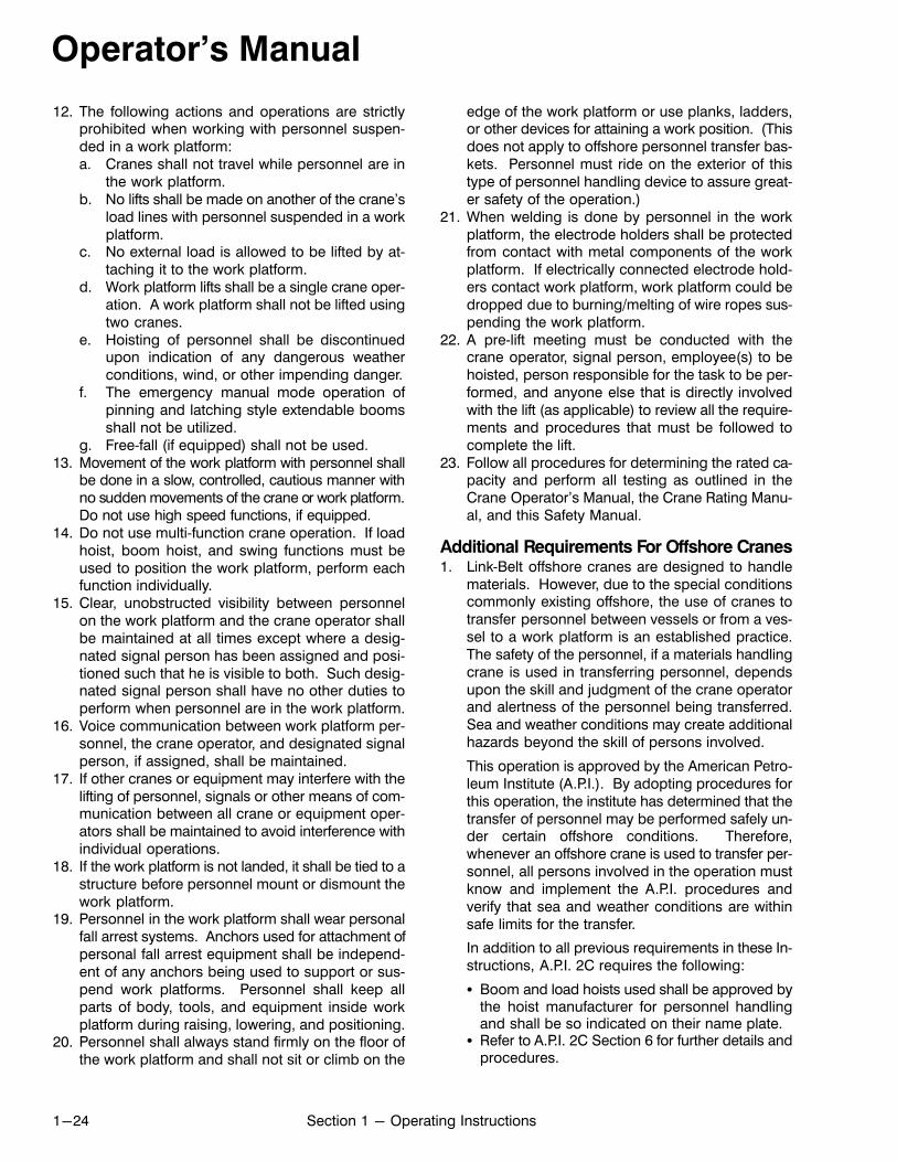
Operator's Manual
1-24 Section 1 - Operating Instructions
12. The following actions and operations are strictlyprohibited when working with personnel suspended in a work platform:a. Cranes shall not travel while personnel are in
the work platform.b. No lifts shall be made on another of the crane's
load lines with personnel suspended in a workplatform.
c. No external load is allowed to be lifted by attaching it to the work platform.
d. Work platform lifts shall be a single crane operation. A work platform shall not be lifted usingtwo cranes.
e. Hoisting of personnel shall be discontinuedupon indication of any dangerous weatherconditions, wind, or other impending danger.
f. The emergency manual mode operation ofpinning and latching style extendable boomsshall not be utilized.
g. Free‐fall (if equipped) shall not be used.13. Movement of the work platform with personnel shall
be done in a slow, controlled, cautious manner withno sudden movements of the crane or work platform.Do not use high speed functions, if equipped.
14. Do not use multi‐function crane operation. If loadhoist, boom hoist, and swing functions must beused to position the work platform, perform eachfunction individually.
15. Clear, unobstructed visibility between personnelon the work platform and the crane operator shallbe maintained at all times except where a designated signal person has been assigned and positioned such that he is visible to both. Such designated signal person shall have no other duties toperform when personnel are in the work platform.
16. Voice communication between work platform personnel, the crane operator, and designated signalperson, if assigned, shall be maintained.
17. If other cranes or equipment may interfere with thelifting of personnel, signals or other means of communication between all crane or equipment operators shall be maintained to avoid interference withindividual operations.
18. If the work platform is not landed, it shall be tied to astructure before personnel mount or dismount thework platform.
19. Personnel in the work platform shall wear personalfall arrest systems. Anchors used for attachment ofpersonal fall arrest equipment shall be independent of any anchors being used to support or suspend work platforms. Personnel shall keep allparts of body, tools, and equipment inside workplatform during raising, lowering, and positioning.
20. Personnel shall always stand firmly on the floor ofthe work platform and shall not sit or climb on the
edge of the work platform or use planks, ladders,or other devices for attaining a work position. (Thisdoes not apply to offshore personnel transfer baskets. Personnel must ride on the exterior of thistype of personnel handling device to assure greater safety of the operation.)
21. When welding is done by personnel in the workplatform, the electrode holders shall be protectedfrom contact with metal components of the workplatform. If electrically connected electrode holders contact work platform, work platform could bedropped due to burning/melting of wire ropes suspending the work platform.
22. A pre‐lift meeting must be conducted with thecrane operator, signal person, employee(s) to behoisted, person responsible for the task to be performed, and anyone else that is directly involvedwith the lift (as applicable) to review all the requirements and procedures that must be followed tocomplete the lift.
23. Follow all procedures for determining the rated capacity and perform all testing as outlined in theCrane Operator's Manual, the Crane Rating Manual, and this Safety Manual.
Additional Requirements For Offshore Cranes1. Link‐Belt offshore cranes are designed to handle
materials. However, due to the special conditionscommonly existing offshore, the use of cranes totransfer personnel between vessels or from a vessel to a work platform is an established practice.The safety of the personnel, if a materials handlingcrane is used in transferring personnel, dependsupon the skill and judgment of the crane operatorand alertness of the personnel being transferred.Sea and weather conditions may create additionalhazards beyond the skill of persons involved.
This operation is approved by the American Petroleum Institute (A.P.I.). By adopting procedures forthis operation, the institute has determined that thetransfer of personnel may be performed safely under certain offshore conditions. Therefore,whenever an offshore crane is used to transfer personnel, all persons involved in the operation mustknow and implement the A.P.I. procedures andverify that sea and weather conditions are withinsafe limits for the transfer.
In addition to all previous requirements in these Instructions, A.P.I. 2C requires the following:
� Boom and load hoists used shall be approved bythe hoist manufacturer for personnel handlingand shall be so indicated on their name plate.
� Refer to A.P.I. 2C Section 6 for further details andprocedures.

Operator's Manual
1-25Section 1 - Operating Instructions
Personnel HandlingPre‐Lift Check List for Link‐Belt Cranes
1
I am the designated person responsible for verifying that all safety requirements are met for thispersonnel handling operation;
Name: Title:
Signature: Date: / / Initials
2 I have verified that there are no conventional means to handle personnel for this operation.
3I have a written statement authorizing personnel handling from a competent person on the jobwho accepts full responsibility, or I accept full responsibility for the operation.
4The Crane Operator acknowledges that he has read and fully understands the CraneOperator's Manual and Crane Rating Manual. All personnel involved have been informed andunderstand the tasks required to complete the personnel lifting operation.
5The crane has been maintained, lubricated, and adjusted by a designated person, asspecified in the Crane Operator's Manual.
6 The lift crane is equipped, and all devices operate properly as follows:
� Anti‐two block device with hydraulic cutouts� Power load raising and lowering with automatic brakes and function cutouts - Free‐Fall (if
equipped) shall not be used� Boom angle indicator with high and low set points and function cutouts� Boom length indicator (telescopic booms only) and function cutouts� Load Indicating System or Rated Capacity Limiter System� A variable swing brake or swing controls capable of stopping upper swing motion smoothly� A mechanical swing park brake or swing lock to hold the upper in position while personnel
are working from the work platform� Hook block or hook ball being used can be closed and locked with a safety latch
7 A working audible and visual alert system is provided to the personnel in the work platform.
8 A mechanical and structural crane inspection has been completed by a designated person.
9 The wire rope used to lift the work platform is reeved from an allowed lifting sheave
10 Crane travel is not allowed with personnel in the work platform.
11 Telescoping the boom is not recommended with personnel in the work platform.
12When handling personnel with pinning and latching style booms, it is recommended boom bekept in a pinned position. Inspections must be made to ensure boom extend pins are set.
13 All wire rope sockets and dead end lugs are properly installed and are in good working condition. All Wire rope guards are properly installed and adjusted to hold all ropes on the appropriate sheaves.
14Voice communications between the Crane Operator and the personnel in the work platformare present and operational.
15 Fall arrest systems are present and in use by personnel in the work platform.
16 Weather and wind conditions are acceptable to safely perform the lift.
17 A Proof‐Test/Trial Lift was completed with 125% of the work platform's rated capacity.
18 The total load being lifted will not exceed 50% of the standard lift crane capacity charts.
19 Cranes with outriggers have them equally extended with tires clear of the ground.
20 A Pre‐Lift meeting was held with all appropriate personnel to review all aspects of the lift.
Note: This checklist is to be used as a supplement to (not a substitute for) the information and proceduressupplied for personnel handling operations.
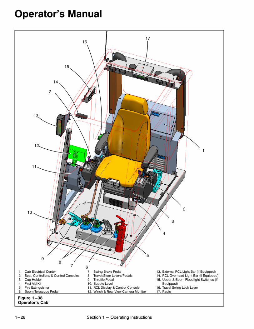
Operator's Manual
1-26 Section 1 - Operating Instructions
Figure 1-38Operator's Cab
1. Cab Electrical Center2. Seat, Controllers, & Control Consoles3. Cup Holder4. First Aid Kit5. Fire Extinguisher6. Boom Telescope Pedal
7. Swing Brake Pedal8. Travel/Steer Levers/Pedals9. Throttle Pedal10. Bubble Level11. RCL Display & Control Console12. Winch & Rear View Camera Monitor
13. External RCL Light Bar (If Equipped)14. RCL Overhead Light Bar (If Equipped)15. Upper & Boom Floodlight Switches (If
Equipped)16. Travel Swing Lock Lever17. Radio
9
13
3
112
5
67
210
8
1617
14
11
2
15
4

Operator's Manual
1-27Section 1 - Operating Instructions
Operator's CabSeveral panels which contain the gages, switches, andcontrols to operate and monitor crane operations aremounted throughout the operator's cab. Refer toFigure 1-38. The following is a description of eachgauge, switch, or control in each panel, along with anexplanation of their function and/or operation.
Bubble LevelThe bubble level is provided to assist the operator indetermining when the crane is level. It is on the lowerright front of the operator's cab. Refer to Figure 1-38.
Fire ExtinguisherA fire extinguisher is mounted in the left front corner of theoperator's cab. Refer to Figure 1-38. It is an ABC typefire extinguisher, meaning it is capable of extinguishingmost types of fires. The operator should be familiar withits location, the clamp mechanism used to secure it inplace, and foremost the operation of the device. Specificinstructions, regarding operation, are given on the labelon the fire extinguisher. A charge indicator on the fire extinguisher monitors the pressure within the tank. Checkthe indicator daily to ensure the fire extinguisher is adequately charged and ready for use.
RCL Overhead Light Bar (If Equipped)The operator's cab may be equipped with an overheadlight bar which gives a visual indication of how much ofthe crane's capacity is being used and the rate at whichan overload is being approached. This light bar operatessimilar to the bar‐graph on the RCL Display. Refer to“Rated Capacity Limiter” in this Section of this Operator'sManual for additional information.
External RCL Light Bar (If Equipped)An external RCL light bar may be mounted on the outsidetop right corner of the operator's cab. It gives groundpersonnel a visual indication of how much of the crane'scapacity is being used and the rate at which an overloadis being approached. This light bar operates similar tothe bar‐graph on the RCL Display. Refer to “Rated Capacity Limiter” in this Section of this Operator's Manual foradditional information.
First Aid Kit
The crane has a multi‐purpose first aid kit to the left ofthe operator's seat. Refer to Figure 1-38.
Figure 1-39Top Hatch
1. Sunscreen2. Wiper Motor
3. Latches4. Catch Release
1
2
3 4 3
Top Hatch
Top Hatch Wiper And Washer
The top hatch wiper is mounted in the top of the operator's cab roof. Refer to Figure 1-39. The switch for thetop hatch wiper/washer is on the cab control console.Refer to Figure 1-42 for switch location.
Top Hatch Window
The top hatch window can be opened to improve operator's cab ventilation. To open the top hatch window,rotate the latches, press the catch release, and pushup on the top hatch window. Refer to Figure 1-39.
Top Hatch Sunscreen
The top hatch is equipped with a roller type sunscreento assist operator vision when looking up through thetop hatch. Refer to Figure 1-39.

Operator's Manual
1-28 Section 1 - Operating Instructions
Figure 1-40Cab Electrical Center
1. RCL Control Module Diagnostic Connector2. Junction Block3. Solid State Flasher4. Rear View Camera Power Harness Unit5. Diode Packs6. Wind Speed Indicator Receiver
7. RCL Controller8. 75 Amp Relay Module9. Drum Rotation Indicator Controller10. Cab Fuse Box Access Panel11. Cab Fuse Box
11
10
78
96
5
4
1
3
2
2
RCL Control Module Diagnostic
Connector
A diagnostic connector is located behind the operator'sseat for initial calibration or extensive troubleshootingfor the RCL control module. Refer to Figure 1-40. Extensive troubleshooting requires a laptop computer,diagnostic software, and a factory trained technician.Contact your Link‐Belt Distributor if extensive troubleshooting is required.
Cab Electrical CenterThe cab electrical center is mounted behind the operator's seat. Refer to Figure 1-38 and Figure 1-40. Remove the access panels to gain access to electricalcomponents within the electrical center. The electricalcenter contains the fuse box, the RCL control module,and other various electrical components for the crane.
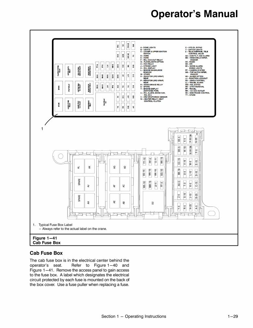
Operator's Manual
1-29Section 1 - Operating Instructions
Figure 1-41Cab Fuse Box
SPAR
E
LL-5
KK-1
0JJ
-5
GG
-10
FF-5
MM
-10
NN
-10
PP-5
RR
-10
SS-1
5TT
-15
HH
-15
UU
F-5
G-2
5
N-R
1.0K
P-R
1.0K
W-1
0X-
5
DD
-5EE
-5
A-5
B-25
C-1
5D
-10
E-15
H-2
5J-
10K-
5L-
10M
-5
R-5
S-10
T-3
U-5
V-10
Y-5
Z-5
AA-5
BB-1
0C
C-1
5
ALSP
ARE
AJAH
AK
ACAB
AD
AEAF
AG
A
1. Typical Fuse Box Label- Always refer to the actual label on the crane.
1
Cab Fuse Box
The cab fuse box is in the electrical center behind theoperator's seat. Refer to Figure 1-40 andFigure 1-41. Remove the access panel to gain accessto the fuse box. A label which designates the electricalcircuit protected by each fuse is mounted on the back ofthe box cover. Use a fuse puller when replacing a fuse.

Operator's Manual
1-30 Section 1 - Operating Instructions
Figure 1-42Cab Control Console
1. Emergency Engine Shutdown Button2. Winch & Rear View Cameras Monitor3. Crane Control Display4. RCL Display5. Fan Speed Switch6. Heater/Air Conditioner Selector Switch7. Rotating Beacon or Strobe Light Switch
(If Equipped)8. Upper Driving Lights Switch9. Travel Control Switch10. Cab Tilt Switch
11. Side Frame Extend/Retract Switch12. Ignition Switch13. 12V DC Accessory Outlet14. Top Hatch Wiper/Washer Switch15. Windshield Wiper/Washer Switch16. Auger Activation Switch (If Equipped)17. Auger Lock/Unlock Switch (If Equipped)18. Temperature Control Knob19. RCL Display Diagnostic Connector20. Engine Diagnostic Connector21. Crane Control Display (CCD) Diagnostic Connector
6
1
3
15
13
19
12
18
5
11
9
21
8
20
7
2
4
10
1416
17
Cab Control Console
A panel that contains the following controls, gauges,and indicators is mounted inside the right front cornerof the operator's cab and is shown in Figure 1-42.
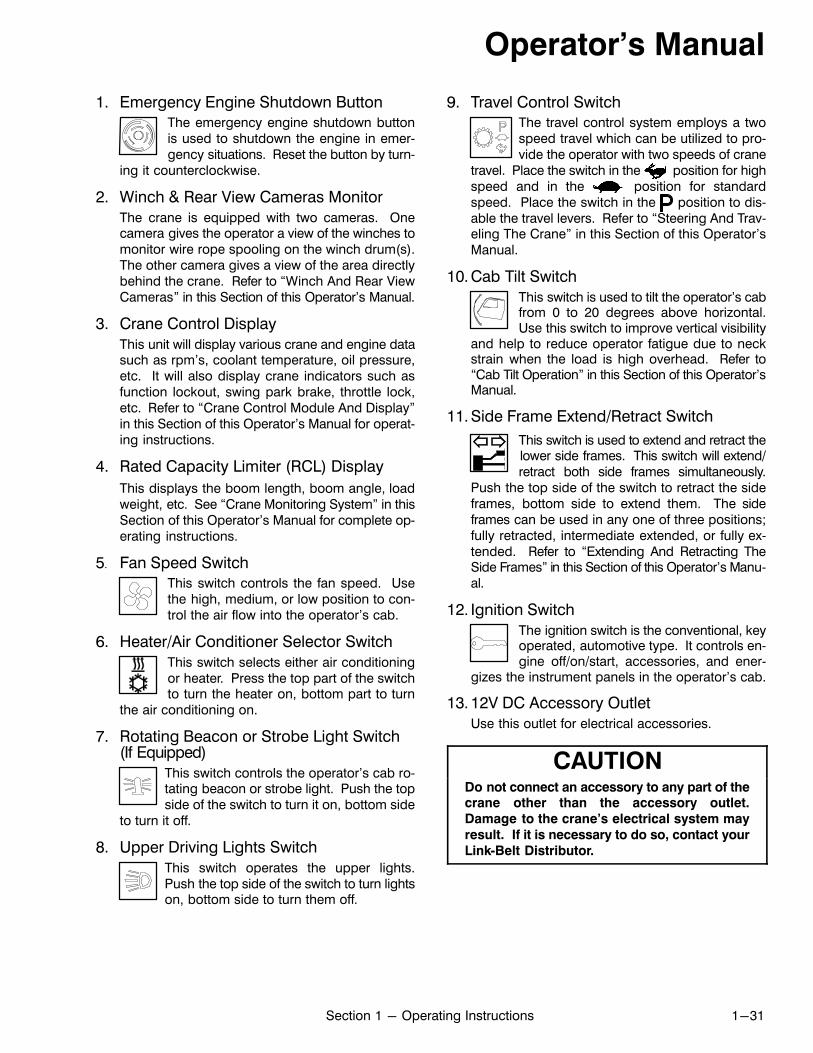
Operator's Manual
1-31Section 1 - Operating Instructions
1. Emergency Engine Shutdown ButtonThe emergency engine shutdown buttonis used to shutdown the engine in emergency situations. Reset the button by turn
ing it counterclockwise.
2. Winch & Rear View Cameras Monitor
The crane is equipped with two cameras. Onecamera gives the operator a view of the winches tomonitor wire rope spooling on the winch drum(s).The other camera gives a view of the area directlybehind the crane. Refer to “Winch And Rear ViewCameras” in this Section of this Operator's Manual.
3. Crane Control Display
This unit will display various crane and engine datasuch as rpm's, coolant temperature, oil pressure,etc. It will also display crane indicators such asfunction lockout, swing park brake, throttle lock,etc. Refer to “Crane Control Module And Display”in this Section of this Operator's Manual for operating instructions.
4. Rated Capacity Limiter (RCL) Display
This displays the boom length, boom angle, loadweight, etc. See “Crane Monitoring System” in thisSection of this Operator's Manual for complete operating instructions.
5. Fan Speed SwitchThis switch controls the fan speed. Usethe high, medium, or low position to control the air flow into the operator's cab.
6. Heater/Air Conditioner Selector Switch
This switch selects either air conditioningor heater. Press the top part of the switchto turn the heater on, bottom part to turn
the air conditioning on.
7. Rotating Beacon or Strobe Light Switch(If Equipped)
This switch controls the operator's cab rotating beacon or strobe light. Push the topside of the switch to turn it on, bottom side
to turn it off.
8. Upper Driving Lights Switch
This switch operates the upper lights.Push the top side of the switch to turn lightson, bottom side to turn them off.
9. Travel Control SwitchThe travel control system employs a twospeed travel which can be utilized to provide the operator with two speeds of crane
travel. Place the switch in the position for highspeed and in the position for standardspeed. Place the switch in the position to disable the travel levers. Refer to “Steering And Traveling The Crane” in this Section of this Operator'sManual.
10. Cab Tilt Switch
This switch is used to tilt the operator's cabfrom 0 to 20 degrees above horizontal.Use this switch to improve vertical visibility
and help to reduce operator fatigue due to neckstrain when the load is high overhead. Refer to“Cab Tilt Operation” in this Section of this Operator'sManual.
11. Side Frame Extend/Retract Switch
This switch is used to extend and retract thelower side frames. This switch will extend/retract both side frames simultaneously.
Push the top side of the switch to retract the sideframes, bottom side to extend them. The sideframes can be used in any one of three positions;fully retracted, intermediate extended, or fully extended. Refer to “Extending And Retracting TheSide Frames” in this Section of this Operator's Manual.
12. Ignition Switch
The ignition switch is the conventional, keyoperated, automotive type. It controls engine off/on/start, accessories, and ener
gizes the instrument panels in the operator's cab.
13. 12V DC Accessory Outlet
Use this outlet for electrical accessories.
CAUTIONDo not connect an accessory to any part of thecrane other than the accessory outlet.
Damage to the crane's electrical system may
result. If it is necessary to do so, contact your
Link‐Belt Distributor.

Operator's Manual
1-32 Section 1 - Operating Instructions
14. Top Hatch Wiper/Washer Switch
Rotate the wiper/washer switch clockwiseto activate the top hatch wiper. Rotate theswitch to the first detent for low speed wip
er and to the second detent for high speed wiper.Rotate the switch counterclockwise to turn thewipers off. Pushing the wiper/washer switchsprays washer fluid on the top hatch window toclean the window.
15. Windshield Wiper/Washer Switch
Rotate the wiper/washer switch clockwiseto activate the windshield wiper. Rotatethe switch to the first detent for low speed
wiper and to the second detent for high speed wiper. Rotate the switch counterclockwise to turn thewipers off. Pushing the wiper/washer switchsprays washer fluid on the windshield to clean thewindshield.
16. Auger Activation Switch (If Equipped)
This switch activates the left control lever to beused as the auger control. Refer to “Auger Attachment” in Section 4 of this Operator's Manual for additional information.
17. Auger Lock/Unlock Switch (If Equipped)
This switch is used to lock or unlock the auger attachment to the lower storage bracket. Refer to“Auger Attachment” in Section 4 of this Operator'sManual for additional information.
18. Temperature Control Knob
Turn the temperature control knob to adjust thetemperature in the operator's cab.
RCL Display Diagnostic ConnectorA diagnostic connector is on the left side of the CabControl Console for initial calibration or extensivetroubleshooting for the RCL Display. Refer toFigure 1-42. Extensive troubleshooting requires a laptop computer, diagnostic software, and a factorytrained technician. Contact your Link‐Belt Distributor ifextensive troubleshooting is required.
Engine Diagnostic ConnectorThe engine diagnostic connector is on the Cab ControlConsole. Refer to Figure 1-42. The diagnostic connector provides access to diagnostic codes within the enginecontrol module (ECM). When the check or stop enginelight illuminates, the service technician can plug in a datareader or laptop computer to retrieve the engine faultcodes stored in the ECM. Refer to the engine manufacturer's manual for information on engine diagnostics andengine fault code descriptions.
Crane Control Display (CCD)Diagnostic ConnectorA diagnostic connector is on the left side of the CabControl Console for initial calibration or extensivetroubleshooting for the Crane Control Display. Refer toFigure 1-42. Extensive troubleshooting requires a laptop computer, diagnostic software, and a factorytrained technician. Contact your Link‐Belt Distributor ifextensive troubleshooting is required.
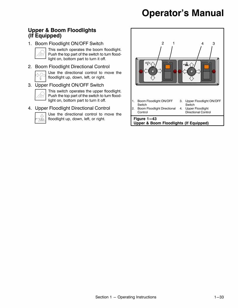
Operator's Manual
1-33Section 1 - Operating Instructions
Upper & Boom Floodlights(If Equipped)
1. Boom Floodlight ON/OFF Switch
This switch operates the boom floodlight.Push the top part of the switch to turn floodlight on, bottom part to turn it off.
2. Boom Floodlight Directional Control
Use the directional control to move thefloodlight up, down, left, or right.
3. Upper Floodlight ON/OFF Switch
This switch operates the upper floodlight.Push the top part of the switch to turn floodlight on, bottom part to turn it off.
4. Upper Floodlight Directional Control
Use the directional control to move thefloodlight up, down, left, or right. Figure 1-43
Upper & Boom Floodlights (If Equipped)
1. Boom Floodlight ON/OFFSwitch
2. Boom Floodlight DirectionalControl
3. Upper Floodlight ON/OFFSwitch
4. Upper FloodlightDirectional Control
1 32 4
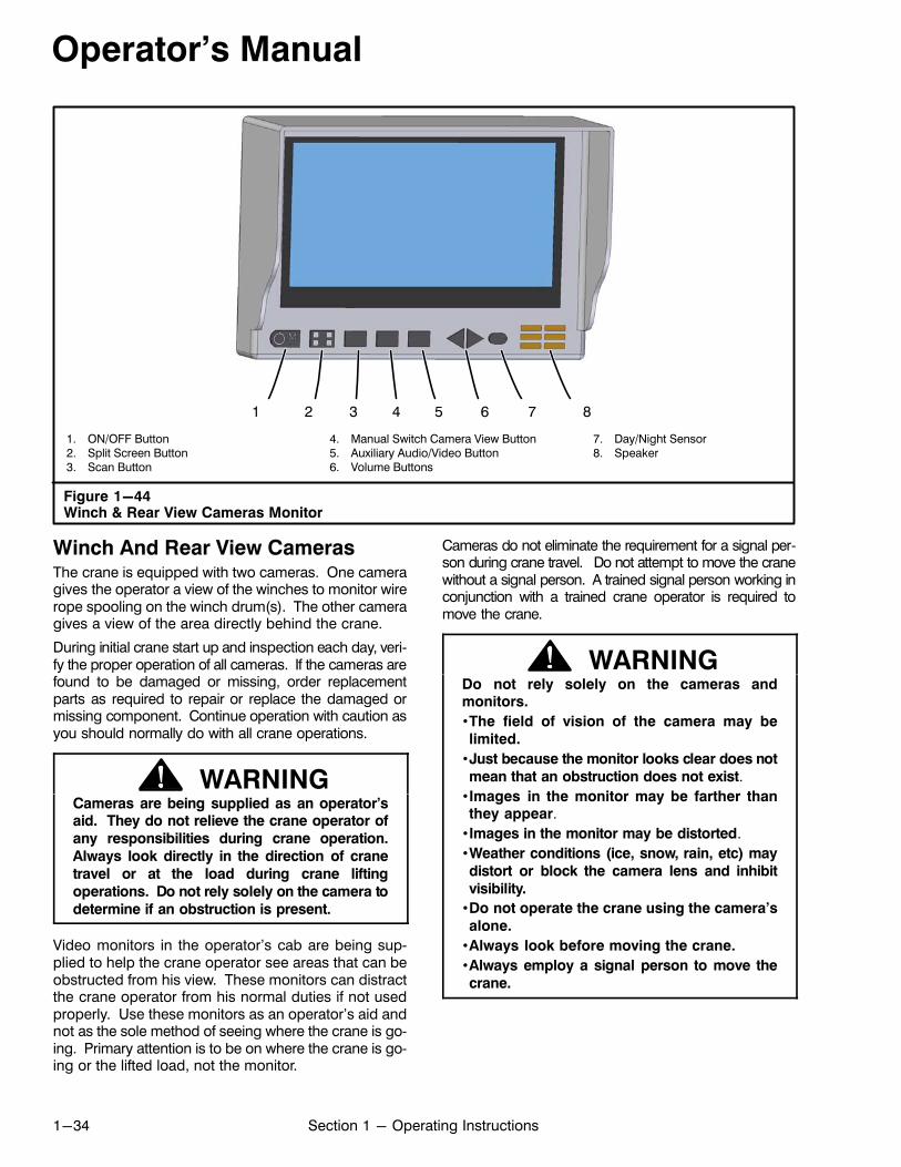
Operator's Manual
1-34 Section 1 - Operating Instructions
1. ON/OFF Button2. Split Screen Button3. Scan Button
4. Manual Switch Camera View Button5. Auxiliary Audio/Video Button6. Volume Buttons
7. Day/Night Sensor8. Speaker
Figure 1-44Winch & Rear View Cameras Monitor
1 2 3 4 5 6 7 8
Winch And Rear View CamerasThe crane is equipped with two cameras. One cameragives the operator a view of the winches to monitor wirerope spooling on the winch drum(s). The other cameragives a view of the area directly behind the crane.
During initial crane start up and inspection each day, verify the proper operation of all cameras. If the cameras arefound to be damaged or missing, order replacementparts as required to repair or replace the damaged ormissing component. Continue operation with caution asyou should normally do with all crane operations.
WARNINGCameras are being supplied as an operator’said. They do not relieve the crane operator of
any responsibilities during crane operation.
Always look directly in the direction of crane
travel or at the load during crane lifting
operations. Do not rely solely on the camera to
determine if an obstruction is present.
Video monitors in the operator’s cab are being supplied to help the crane operator see areas that can beobstructed from his view. These monitors can distractthe crane operator from his normal duties if not usedproperly. Use these monitors as an operator’s aid andnot as the sole method of seeing where the crane is going. Primary attention is to be on where the crane is going or the lifted load, not the monitor.
Cameras do not eliminate the requirement for a signal person during crane travel. Do not attempt to move the cranewithout a signal person. A trained signal person working inconjunction with a trained crane operator is required tomove the crane.
WARNINGDo not rely solely on the cameras andmonitors.
•The field of vision of the camera may be
limited.
•Just because the monitor looks clear does not
mean that an obstruction does not exist.
•Images in the monitor may be farther thanthey appear.
•Images in the monitor may be distorted.
•Weather conditions (ice, snow, rain, etc) may
distort or block the camera lens and inhibit
visibility.
•Do not operate the crane using the camera’s
alone.
•Always look before moving the crane.
•Always employ a signal person to move the
crane.

0%
Operator's Manual
1-35Section 1 - Operating Instructions
1. Hydraulic Oil Temperature Gauge2. Fine Metering Level Indicator3. Coolant Temperature Gauge4. Tachometer5. Fuel Level Gauge6. Fine Metering Indicator Light7. Hydraulic Oil Temperature Indicator Light8. Hydraulic Pump Controller Indicator Light9. Battery Indicator Light
10. Engine Oil Pressure Indicator Light11. Coolant Temperature Indicator Light12. DPF System Indicator Lights13. Stop Engine Indicator Light14. Check Engine Indicator Light15. Wait To Start Indicator Light16. Swing Park Brake Indicator Light17. Up And Down Arrow Buttons
18. OK Button19. Throttle Lock Indicator20. Menu Button21. Back Button22. Function Key F423. Function Key F324. Function Key F225. Function Key F1
Figure 1-45Crane Control Display (Main Working Screen Shown)
1
3
5
17
18
17
19
4
2
202122232425
16
7 8 119 10 13 14
6
12 15
Crane Control DisplayThe Crane Control Display contains the following controls, gauges, and indicators and is on the Crane Control Console. Refer to Figure 1-42 and Figure 1-45.
1. Hydraulic Oil Temperature GaugeThis gauge registers the hydraulic oil temperature in the main return line. Normal operating ranges vary with the oils used in dif
ferent climates. Refer to Section 2 of this Operator's Manual for proper oil viscosities and operating temperature ranges. If the hydraulic oil ex
ceeds the maximum operating temperature, thehydraulic oil temperature indicator light will illuminate and an alarm buzzer will sound. Also the indicator light within the gauge will change fromwhite to red. If the system overheats, shutdown thecrane immediately and correct the problem.
2. Fine Metering Level Indicator
This indicator alerts the operator of the finemetering level. Refer to “Fine Metering Control” in this Section of this Operator's Manual.

Operator's Manual
1-36 Section 1 - Operating Instructions
3. Coolant Temperature GaugeThis gauge registers the engine cooling system temperature. For proper cooling system operating temperature range, refer to
the engine manufacturer's manual. If the coolingsystem overheats, reduce engine speed until thetemperature returns to normal operating range. Ifengine temperature does not return to normal temperature, refer to engine manufacturer's manual.When the coolant temperature exceeds normal operating range an indicator light will illuminate, analarm buzzer will sound, and the stop engine indicator light will illuminate. Also the indicator light withinthe gauge will change from white to red.
4. Tachometer
The tachometer registers engine speed inrevolutions per minute (rpm). Refer to theengine manufacturer's manual for sug
gested operating speeds.
5. Fuel Level Gauge
This gauge registers the level of fuel in the fueltank. The fuel tank capacity is 110 gal (416L).Refer to the engine manufacturer's manual for
the correct grade of diesel fuel. When the fuel levelreaches an eighth of a tank, the indicator light within thegauge will change from white to yellow.
6. Fine Metering Indicator Light
This indicator alerts the operator that thefine metering system has been enabled.Refer to “Fine Metering Control” in this Sec
tion of this Operator's Manual.
7. Hydraulic Oil Temperature Indicator Light
This red indicator light will illuminate alongwith an alarm buzzer to alert the operatorthat the hydraulic oil exceeds the maximum
operating temperature. If the system overheats,shutdown the crane immediately and correct theproblem.
8. Hydraulic Pump Controller Indicator LightThis red indicator light will illuminate along withan error message pop‐up screen to alert theoperator of a problem with the main hydraulic
pump controller. Communicate the pump controllerproblem to a Link‐Belt Distributor and correct the erroras soon as possible.
9. Battery Indicator Light
This red indicator light will illuminate alongwith an alarm buzzer to alert the operatorthat the charge or the voltage in the battery
is not within normal operating range.
10. Engine Oil Pressure Indicator LightThis red indicator light will illuminate alongwith an alarm buzzer to alert the operatorthat the engine oil pressure is not within
normal operating range. For proper oil pressureoperating range, refer to the engine manufacturer's manual. If there is no engine oil pressure after10-15 seconds of running time, shutdown the engine immediately and repair the problem to avoidengine damage.
11. Coolant Temperature Indicator Light
This red indicator light will illuminate alongwith an alarm buzzer to alert the operatorthat the engine cooling system temperat
ure exceeds the maximum operating temperature.For proper cooling system operating temperaturerange, refer to the engine manufacturer's manual.If the cooling system overheats, reduce enginespeed until the temperature returns to normal operating range. If engine temperature does not return to normal temperature, refer to engine manufacturer's manual. When the coolant temperatureexceeds normal operating range, the stop engineindicator light will also illuminate.
12. DPF System Indicator Lights
These indicator lights will illuminate duringvarious DPF operations. Refer to “DieselParticulate Filter (DPF)” in this Section ofthis Operator's Manual.
13. Stop Engine Indicator Light
This red indicator light will illuminate alongwith an alarm buzzer and an error messagepop‐up screen to alert the operator of major
engine problems. When this light illuminates stopoperations immediately and shutdown the engine.Refer to the engine manufacturer's manual and determine the problem before any further operationof the engine.
14. Check Engine Indicator Light
This yellow indicator light will illuminatealong with an error message pop‐upscreen to make the operator aware of
minor engine problems. When this light illuminatesengine operation may continue. However, refer tothe engine manufacturer's manual and determinethe problem as soon as possible to avoid prolongedoperation of the malfunctioning engine which coulddevelop into a major problem.

F4
F3
F2
F1
Operator's Manual
1-37Section 1 - Operating Instructions
15. Wait To Start Indicator LightThis green indicator light will illuminate incold weather when the ignition switch is inthe “ON” position to alert the operator not to
crank the engine. During cold weather conditionsthe light illuminates and an engine air intake heaterwill activate to heat the air before entering the engineair intake. When the air intake is warm enough theindicator light will go out and then the engine can bestarted. This aids in engine start‐up in cold weatherconditions and reduces white smoke after starting.For additional information refer to “Cold Engine Starting” in this Section of this Operator's Manual.
16. Swing Park Brake Indicator LightThis light will illuminate anytime the swingpark brake is applied and the ignition is on.
17. Up And Down Arrow Buttons
These are navigation buttons that are usedto scroll through selections on a menupage.
18. OK Button
Pushing this button equals “enter”. Savesthe value or confirms the selection.
19. Throttle Lock Indicator
This indicator alerts the operator that thethrottle lock system is locked or unlocked . Refer to “Throttle Lock System”
in this Section of this Operator's Manual.
20. Menu Button
Push this button to bring up a menu page.
21. Back Button
Push this button to return to the previousdisplay page.
22. Function Key F4
This function key will bring up the first layer/third wrap calibration screen (if equipped).Refer to “First Layer/Third Wrap Calibra
tion” in Section 3 of this Operator's Manual.
23. Function Key F3
This function key will bring up the enginedata screen. Refer to “Engine DataScreen” in this Section of this Operator's
Manual.
24. Function Key F2
This function key will bring up the finemetering screen. Refer to “Fine MeteringControl” in this Section of this Operator's
Manual.
25. Function Key F1
This function key has no function when themain working screen is displayed.

n‐1
ThrottlePedal
Operator's Manual
1-38 Section 1 - Operating Instructions
1. Engine RPM2. Throttle Pedal Position3. Engine Oil Temperature4. Engine Oil Pressure5. Coolant Temperature6. Battery Voltage Output
7. Engine Hour Meter8. Engine Load9. Fuel Consumption10. Function Key F2 - DPF Regeneration Inhibit Switch11. Function Key F1 - DPF (Parked) Manual Regeneration Switch
Figure 1-46Engine Data And Aftertreatment Control Screen
2
5
8
1
6
3
7
4
9
1011
Engine Data And Aftertreatment Control
Screen
The engine data and aftertreatment control screen canbe displayed by pressing the Function Key F3 on theCrane Control Display. Press the back button to return to the main working screen. The following describes the data displayed on the engine data screen.
1. Engine RPM
This displays the actual engine speed inrevolutions per minute (rpm). Refer to theengine manufacturer's manual for sug
gested operating speeds.
2. Throttle Pedal Position
This indicator light will illuminate anytimethe throttle pedal is depressed and the vertical bar‐graph will indicate percentage
pedal is depressed.
3. Engine Oil Temperature
This displays the actual engine oil temperature in degrees Fahrenheit (°F). For properoil temperature operating range, refer to
the engine manufacturer's manual.
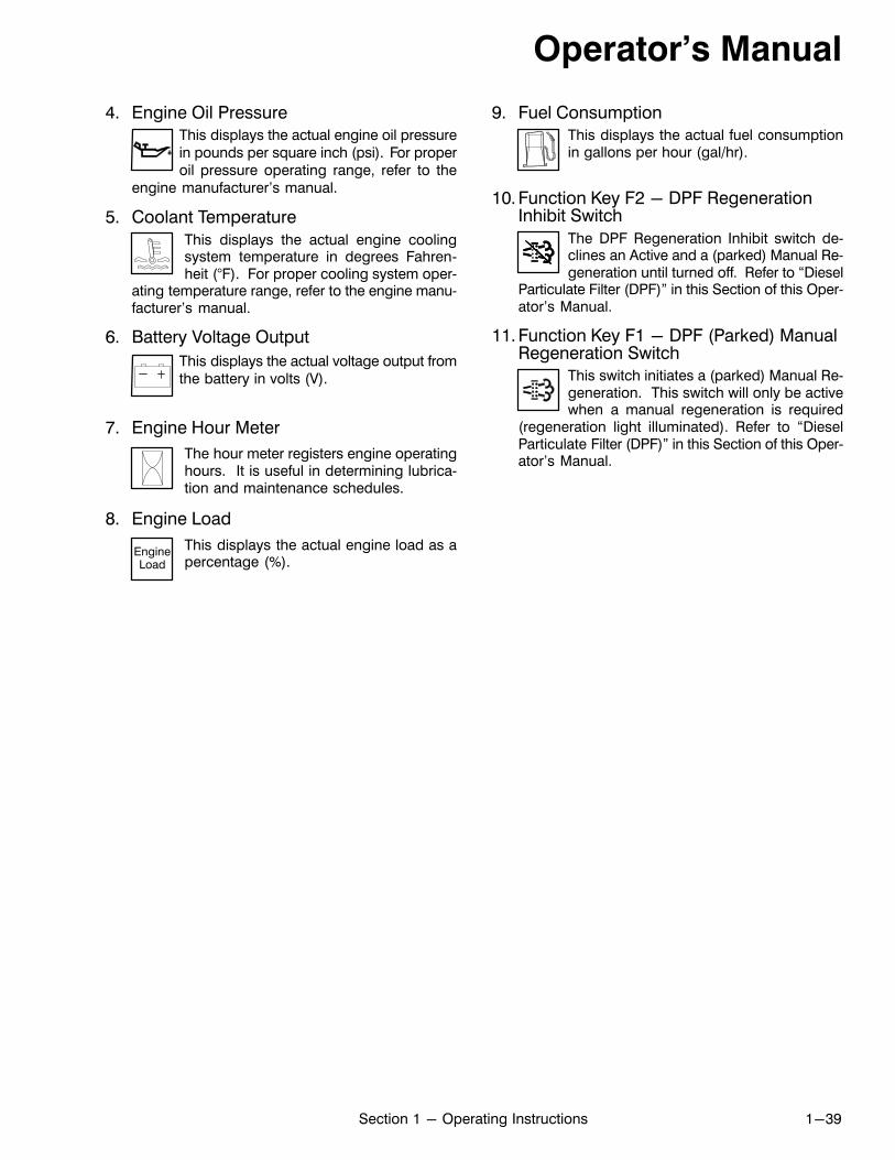
EngineLoad
Operator's Manual
1-39Section 1 - Operating Instructions
4. Engine Oil PressureThis displays the actual engine oil pressurein pounds per square inch (psi). For properoil pressure operating range, refer to the
engine manufacturer's manual.
5. Coolant Temperature
This displays the actual engine coolingsystem temperature in degrees Fahrenheit (°F). For proper cooling system oper
ating temperature range, refer to the engine manufacturer's manual.
6. Battery Voltage Output
This displays the actual voltage output fromthe battery in volts (V).
7. Engine Hour Meter
The hour meter registers engine operatinghours. It is useful in determining lubrication and maintenance schedules.
8. Engine Load
This displays the actual engine load as apercentage (%).
9. Fuel ConsumptionThis displays the actual fuel consumptionin gallons per hour (gal/hr).
10. Function Key F2 - DPF RegenerationInhibit Switch
The DPF Regeneration Inhibit switch declines an Active and a (parked) Manual Regeneration until turned off. Refer to “Diesel
Particulate Filter (DPF)” in this Section of this Operator's Manual.
11. Function Key F1 - DPF (Parked) ManualRegeneration Switch
This switch initiates a (parked) Manual Regeneration. This switch will only be activewhen a manual regeneration is required
(regeneration light illuminated). Refer to “DieselParticulate Filter (DPF)” in this Section of this Operator's Manual.

Operator's Manual
1-40 Section 1 - Operating Instructions
Crane Control Display Brightness Adjustment
1. From the main working screen, press the menubutton.
2. Press the Function Key F3 to bring up the Preferences screen.
3. Press the Function Key F1 to bring up the Displayscreen.
4. Press the Function Key F2 to select Backlight.
5. Press the Up/Down Arrow buttons to adjust the display brightness.
6. Press the Function Key F1 to return to the mainworking screen.

Operator's Manual
1-41Section 1 - Operating Instructions
Diesel Particulate Filter (DPF)
The diesel particulate filter (DPF) is designed to removediesel particulate matter or soot from the exhaust gasof the engine. The filter must be periodically regenerated to remove the accumulated soot from the filter.During normal operation, the soot in the DPF will bepurged by an automatic regeneration cycle. In somecases an automatic regeneration may not occur andthe regeneration cycle must be initiated manually.
Refer to engine manufacturer's manual for additional information on the regeneration process and procedures.
Engine DPF Regeneration Indicators
1. The DPF regeneration indicator light will illuminateto alert the operator that an active regeneration ofthe diesel particulate filter is required but cannotoccur. When this light illuminates, ensure the regeneration inhibit switch is off (regeneration inhibitindicator light is off), increase upper engine load/speed to allow the engine to run until regenerationis complete, or use the engine DPF regenerationswitch to initiate a (parked) manual regenerationcycle as soon as safely possible. Press the Function Key F2 OK button to return to previous screen.
2. The DPF regeneration light begins to flash alertingthe operator that the soot loading in the DPF is nearlyfull. When this light illuminates, ensure the regeneration inhibit switch is off (regeneration inhibit indicator light is off), increase upper engine load/speed to allow the engine to run until regenerationis complete, or use the engine DPF regenerationswitch to initiate a (parked) manual regenerationcycle as soon as safely possible.
3. The DPF regeneration light continues to flash andthe check engine light will illuminate to alert the operator that the soot loading in the DPF is full. Thiscondition alerts the operator that the soot loadingin the DPF has reached a critical level where a(parked) manual regeneration must be performedimmediately. Press the Function Key F2 OK buttonand initiate a (parked) manual regeneration. Referto “DPF (Parked) Manual Regeneration” in this Operator's Manual.
4. The stop engine light will illuminate to alert the operator that the soot loading in the DPF has reacheda critical level and continued operation could resultin damage to the DPF. Stop the engine as soon aspossible and call for service or risk damage to theDPF.

Operator's Manual
1-42 Section 1 - Operating Instructions
Figure 1-47High Exhaust System Temperature Indicator
Light
1. High Exhaust System Temperature Indicator Light
1
High Exhaust System Temperature
Indicator Light
This indicator light will illuminate to alert the operator thatthe outlet temperature in the upper engine exhaust system is above normal. This condition can occur undernormal operation or during an automatic or manual DPFregeneration cycle. No action is required.
DANGERThe temperature of the engine exhaust gasand the exhaust system components can
reach up to 1200°F (650°C) during DPF
regeneration. An unexpected failure of the
engine or regeneration system may increase
exhaust gas temperature at the particulate
exhaust filter to as high as 1650°F (900°C).
This may result in fire, burn, or explosionhazards, which may result in serious personal
injury or death. Do not expose flammable
material or explosive atmospheres to exhaust
gas or to exhaust system components during
DPF regeneration.
Engine DPF Regeneration Inhibit Switch
The engine DPF regeneration inhibit switch disablesany automatic or manual regeneration of the upper engine diesel particulate filter. It may be used to preventany regeneration when the crane is operating in a hazardous environment and there is a concern about hightemperatures from the DPF system.
1. To access the DPF Regeneration Inhibit Switch,press the Function Key F3 from the main workingscreen.
2. The main screen will change to the engine dataand aftertreatment control screen. From thisscreen, press the Function Key F2 DPF Regeneration Inhibit Switch.
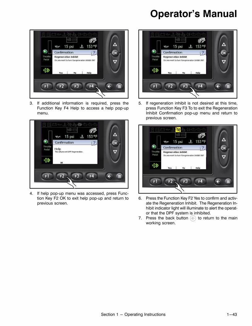
Operator's Manual
1-43Section 1 - Operating Instructions
3. If additional information is required, press theFunction Key F4 Help to access a help pop‐upmenu.
4. If help pop‐up menu was accessed, press Function Key F2 OK to exit help pop‐up and return toprevious screen.
5. If regeneration inhibit is not desired at this time,press Function Key F3 To to exit the RegenerationInhibit Confirmation pop‐up menu and return toprevious screen.
6. Press the Function Key F2 Yes to confirm and activate the Regeneration Inhibit. The Regeneration Inhibit indicator light will illuminate to alert the operator that the DPF system is inhibited.
7. Press the back button to return to the mainworking screen.

Operator's Manual
1-44 Section 1 - Operating Instructions
DPF (Parked) Manual Regeneration
The DPF manual regeneration switch is used to start amanual regeneration only when the DPF regenerationlight is illuminated.
Note: The crane must remain stationary for approximately 45 minutes to complete an engine DPF(parked) manual regeneration.
1. Park the crane in a safe location and apply the swingpark brake. Ensure the regeneration inhibit switch isoff (regeneration inhibit indicator light is off).
2. Engine must be at minimum operating temperature of 140°F (60°C).
3. To access the DPF Manual Regeneration Switch, pressthe Function Key F3 from the main working screen toenter the engine data and aftertreatment controlscreen.
4. The main screen will change to the engine datascreen. From the engine data and aftertreatmentcontrol screen, press the Function Key F1 ManualRegeneration switch to access the Manual Regeneration Confirmation pop‐up menu.
Note: Do not press the engine throttle pedalduring a DPF manual regeneration cycle.Pressing the engine throttle pedal will deactivate the regeneration cycle and the engine willreturn to idle. The engine DPF manual regeneration cycle must be restarted.
5. If additional information is required, press theFunction Key F4 Help to access a help pop‐upmenu.
6. If help pop‐up menu was accessed, press Function Key F2 OK to exit help pop‐up and return toprevious screen.
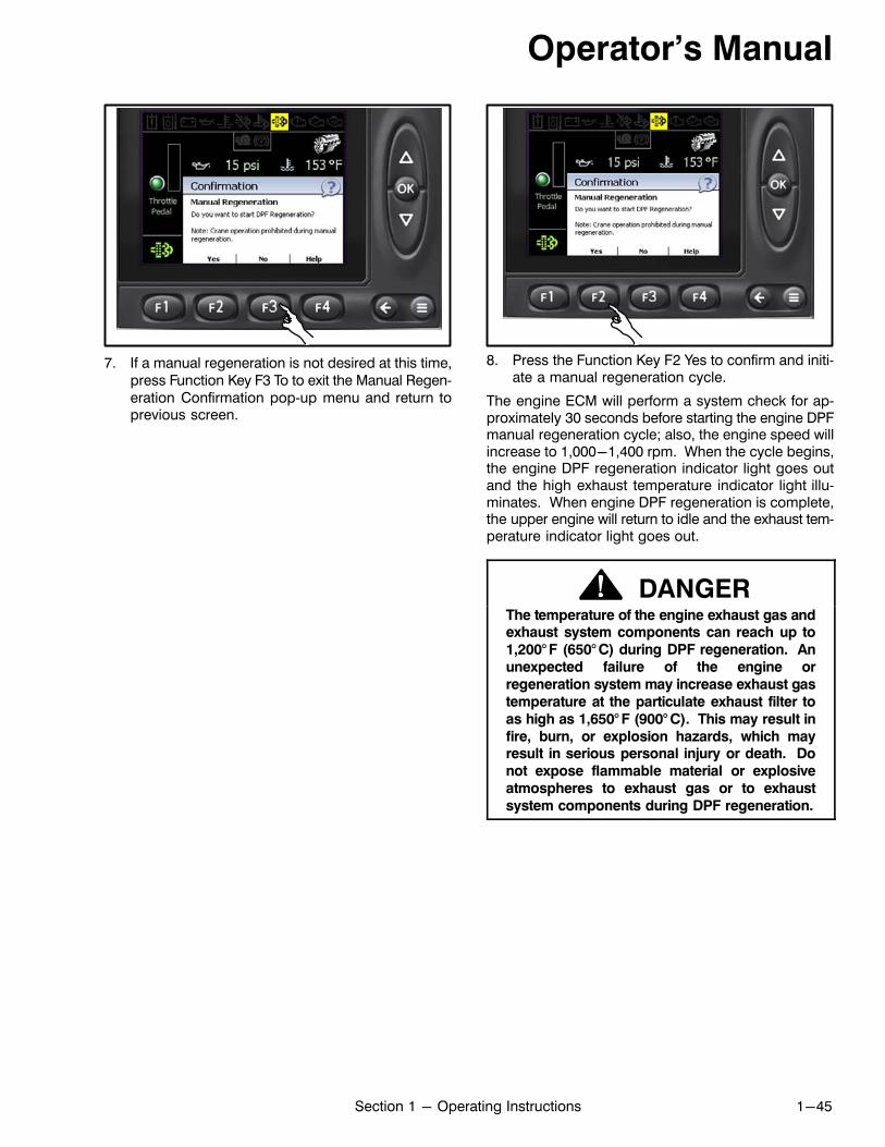
Operator's Manual
1-45Section 1 - Operating Instructions
7. If a manual regeneration is not desired at this time,press Function Key F3 To to exit the Manual Regeneration Confirmation pop‐up menu and return toprevious screen.
8. Press the Function Key F2 Yes to confirm and initiate a manual regeneration cycle.
The engine ECM will perform a system check for approximately 30 seconds before starting the engine DPFmanual regeneration cycle; also, the engine speed willincrease to 1,000-1,400 rpm. When the cycle begins,the engine DPF regeneration indicator light goes outand the high exhaust temperature indicator light illuminates. When engine DPF regeneration is complete,the upper engine will return to idle and the exhaust temperature indicator light goes out.
DANGERThe temperature of the engine exhaust gas andexhaust system components can reach up to
1,200° F (650° C) during DPF regeneration. An
unexpected failure of the engine or
regeneration system may increase exhaust gas
temperature at the particulate exhaust filter to
as high as 1,650° F (900° C). This may result in
fire, burn, or explosion hazards, which mayresult in serious personal injury or death. Do
not expose flammable material or explosive
atmospheres to exhaust gas or to exhaust
system components during DPF regeneration.

Operator's Manual
1-46 Section 1 - Operating Instructions
1. Boom Telescope Override Switches2. Swing Park Brake Switch*3. Front Winch Control Switch
4. Rear Winch Control Switch5. Horn Button*
6. Drum Rotation Indicator Switch7. Function Lockout Switch
*Refer to Figure 1-54 if equipped with joystick controls.
Figure 1-48Seat Console Control Switches
1
2
3
5
6
74
Î
Î
Î
Seat Console Control Switches
Control switches are on the left and right consoles ofthe operator's seat. Refer to Figure 1-48.
1. Boom Telescope Override SwitchesThese switches are provided to manuallyoverride the telescope system when theboom is not extending/retracting proportionally in all boom modes. Use theseswitches for that purpose only. Press the
switch to enter telescope overridemode. Use the switch to select the boom sections to override as follows:
Top position of the switch will override the inner and center sections allowing only the tipand outer sections to extend and retract.
Center position of the switch will override theinner, outer, and tip sections allowing onlythe center section to extend and retract.
The bottom position of the switch will overridethe center, outer, and tip sections allowingonly the inner section to extend and retract.
2. Swing Park Brake SwitchThis switch is used to operate the swingpark brake to hold the upper in any position over the lower. An indicator light on
the Crane Control Display will illuminate to indicatethe switch is in the ON position. Refer to “SwingSystem” in this Section of this Operator's Manualfor complete operating procedures. (Refer toFigure 1-54 if equipped with joystick controls.)
3. Front Winch Control Switch
This switch is used to control engaging/disengaging the high speed hoist anddisabling the front winch. Refer to “Wire
Rope Winch System” in this Section of this Operator's Manual for complete operating procedures.
4. Rear Winch Control Switch
This switch is used to control engaging/disengaging the high speed hoist anddisabling the rear winch. Refer to “Wire
Rope Winch System” in this Section of this Operator's Manual for complete operating procedures.
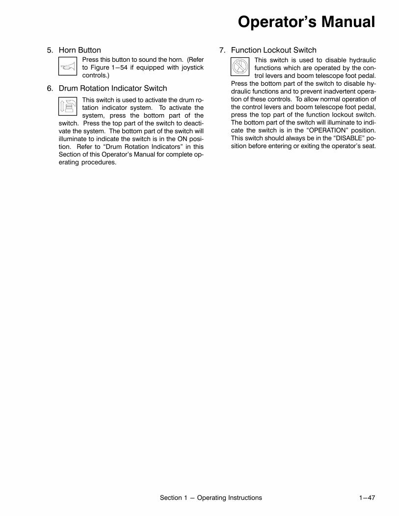
Operator's Manual
1-47Section 1 - Operating Instructions
5. Horn ButtonPress this button to sound the horn. (Referto Figure 1-54 if equipped with joystickcontrols.)
6. Drum Rotation Indicator Switch
This switch is used to activate the drum rotation indicator system. To activate thesystem, press the bottom part of the
switch. Press the top part of the switch to deactivate the system. The bottom part of the switch willilluminate to indicate the switch is in the ON position. Refer to “Drum Rotation Indicators” in thisSection of this Operator's Manual for complete operating procedures.
7. Function Lockout SwitchThis switch is used to disable hydraulicfunctions which are operated by the control levers and boom telescope foot pedal.
Press the bottom part of the switch to disable hydraulic functions and to prevent inadvertent operation of these controls. To allow normal operation ofthe control levers and boom telescope foot pedal,press the top part of the function lockout switch.The bottom part of the switch will illuminate to indicate the switch is in the “OPERATION” position.This switch should always be in the “DISABLE” position before entering or exiting the operator's seat.
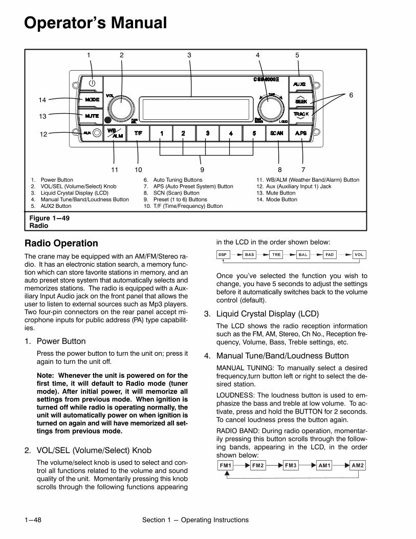
Operator's Manual
1-48 Section 1 - Operating Instructions
1. Power Button2. VOL/SEL (Volume/Select) Knob3. Liquid Crystal Display (LCD)4. Manual Tune/Band/Loudness Button5. AUX2 Button
6. Auto Tuning Buttons7. APS (Auto Preset System) Button8. SCN (Scan) Button9. Preset (1 to 6) Buttons10. T/F (Time/Frequency) Button
11. WB/ALM (Weather Band/Alarm) Button12. Aux (Auxiliary Input 1) Jack13. Mute Button14. Mode Button
Figure 1-49Radio
1 2 3
12
4 5
6
11 8910
13
7
14
Radio Operation
The crane may be equipped with an AM/FM/Stereo radio. It has an electronic station search, a memory function which can store favorite stations in memory, and anauto preset store system that automatically selects andmemorizes stations. The radio is equipped with a Auxiliary Input Audio jack on the front panel that allows theuser to listen to external sources such as Mp3 players.Two four‐pin connectors on the rear panel accept microphone inputs for public address (PA) type capabilities.
1. Power Button
Press the power button to turn the unit on; press itagain to turn the unit off.
Note: Whenever the unit is powered on for thefirst time, it will default to Radio mode (tunermode). After initial power, it will memorize allsettings from previous mode. When ignition isturned off while radio is operating normally, theunit will automatically power on when ignition isturned on again and will have memorized all settings from previous mode.
2. VOL/SEL (Volume/Select) Knob
The volume/select knob is used to select and control all functions related to the volume and soundquality of the unit. Momentarily pressing this knobscrolls through the following functions appearing
in the LCD in the order shown below:
Once you've selected the function you wish tochange, you have 5 seconds to adjust the settingsbefore it automatically switches back to the volumecontrol (default).
3. Liquid Crystal Display (LCD)
The LCD shows the radio reception informationsuch as the FM, AM, Stereo, Ch No., Reception frequency, Volume, Bass, Treble settings, etc.
4. Manual Tune/Band/Loudness Button
MANUAL TUNING: To manually select a desiredfrequency,turn button left or right to select the desired station.
LOUDNESS: The loudness button is used to emphasize the bass and treble at low volume. To activate, press and hold the BUTTON for 2 seconds.To cancel loudness press the button again.
RADIO BAND: During radio operation, momentarily pressing this button scrolls through the following bands, appearing in the LCD, in the ordershown below:
Operator's Manual
1-49Section 1 - Operating Instructions
5. AUX2 Button
When there is a Auxiliary Audio device plugged intothe connector on the rear of the unit, simply pressAUX2 button to enter into AUX2 mode.
6. Auto Tuning Buttons
To automatically select a radio station,press SEEKUP button or TRACK DOWN button. The radio willseek the next acceptable signal strength stationand then stop and remain at that frequency.
7. APS (Auto Preset System) Button
Pressing this button momentarily scans the stations preset 1-5 of the current radio BAND. Scanning will stop at each preset station for approximately 5 seconds before continuing to the next preset station, until all 5 presets have been scanned.Press and hold this button for more than 2 secondsand it will automatically preset 5 stations intomemory (presets 1 to 5) in order of strongest signalstrength.
8. SCN (Scan) Button
Press the Scan button to start scanning the available frequencies. Scanning will pause at eachavailable frequency for approximately 5 secondsand then continue scanning. Press the Scan button to stop scanning at the current broadcast.
9. Preset (1 to 5) Buttons
The preset buttons are used to store favorite radiostations into memory. 15 FM stations and 10 AM stations can be stored in memory (each button canstore 6 stations). Tune the radio to a desired stationthen press and hold one of the preset buttons for 2seconds. The desired station will now be stored inmemory. Once you have completed storing desiredradio stations, simply press each preset button momentarily to check if the correct stations have beenmemorized. To select a station which is stored inmemory, momentarily press any one of the presetbuttons 1 to 5. The station stored in the preset buttonwill automatically be selected. The LCD will show thepreset number and frequency.
10. T/F (Time/Frequency) Button
In any mode, the time display is the default indication on the LCD. When T/F button is pressed whiletime is displayed, the current frequency will appearfor approximately 6 seconds and then revert totime indication.
Setting or Changing the timePress and hold the T/F button until hour digit begins to flash. Rotate volume control knob clockwise to increase hours, rotate volume control knobcounterclockwise to decrease the hours. Pressand hold T/F button again until minute digit beginsto flash. Rotate volume control knob clockwise toincrease the minutes, rotate volume control knobcounterclockwise to decrease the minutes. Oncetime (Hour or Minute) has been adjusted, wait 5seconds until time stops flashing, time is now set.
11. WB/ALM (Weather Band/Alarm) Button
Press and hold this button for 2 seconds to changeinto Alarm mode. Refer to “Setting An Alarm” in thisSection of this Operator's Manual. Momentarilypress the button to change to weather band, thenpress the preset buttons 1-5 to listen to WB presetstations . Refer to “Weather Band” in this Section ofthis Operator's Manual.
12. Aux (Auxiliary Input 1) Jack
Activate the auxiliary input jack by pressing theMode button until AUX In appears on the LCD. Using an Auxiliary Device with the Auxiliary Input Jacka. Obtain an audio cable with 1/8 (3.5mm) male
plug at each end.b. First connect the cable to the radio's auxiliary
input jack, then connect the other end to an external audio device.
c. Press the MODE button until AUX In is displayed on the LCD.
Note: Before selecting AUX In mode, verify thatthe cable is connected to both audio device andthe radio. Since audio devices vary in outputvolume levels, it is recommended that the auxiliary audio device not be set at max outputvolume. Very high output levels from audiodevices may cause audio distortion to the output of the radio.
13. Mute Button
Press this button to mute audio output. Pressagain to enable audio output.
14. Mode Button
Press this button to toggle between radio modeand auxiliary mode.
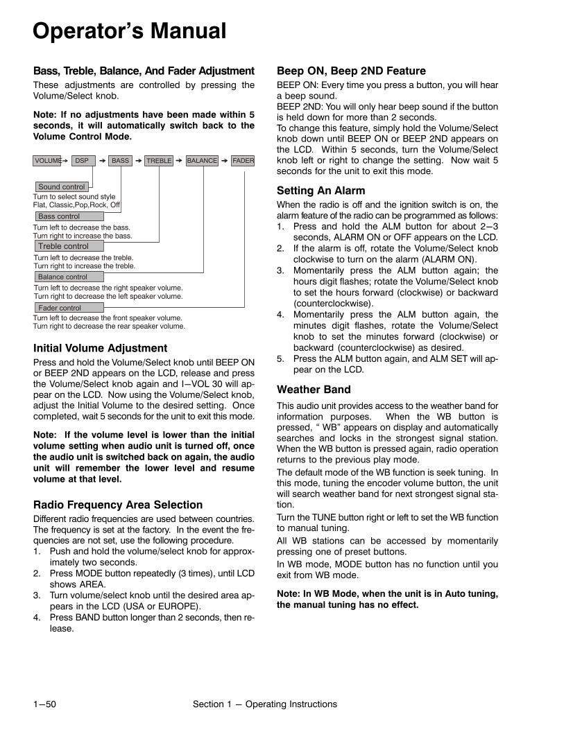
Operator's Manual
1-50 Section 1 - Operating Instructions
Bass, Treble, Balance, And Fader Adjustment
These adjustments are controlled by pressing theVolume/Select knob.
Note: If no adjustments have been made within 5seconds, it will automatically switch back to the
Volume Control Mode.
Turn left to decrease the bass.Turn right to increase the bass.
Turn left to decrease the treble.Turn right to increase the treble.
Turn left to decrease the right speaker volume.Turn right to decrease the left speaker volume.
Turn left to decrease the front speaker volume.Turn right to decrease the rear speaker volume.
VOLUME BASS TREBLE BALANCE FADER
Balance control
Bass control
Treble control
Fader control
Sound control
DSP
Turn to select sound styleFlat, Classic,Pop,Rock, Off
Initial Volume Adjustment
Press and hold the Volume/Select knob until BEEP ONor BEEP 2ND appears on the LCD, release and pressthe Volume/Select knob again and I-VOL 30 will appear on the LCD. Now using the Volume/Select knob,adjust the Initial Volume to the desired setting. Oncecompleted, wait 5 seconds for the unit to exit this mode.
Note: If the volume level is lower than the initial
volume setting when audio unit is turned off, once
the audio unit is switched back on again, the audio
unit will remember the lower level and resume
volume at that level.
Radio Frequency Area Selection
Different radio frequencies are used between countries.The frequency is set at the factory. In the event the frequencies are not set, use the following procedure.1. Push and hold the volume/select knob for approx
imately two seconds.2. Press MODE button repeatedly (3 times), until LCD
shows AREA.3. Turn volume/select knob until the desired area ap
pears in the LCD (USA or EUROPE).4. Press BAND button longer than 2 seconds, then re
lease.
Beep ON, Beep 2ND Feature
BEEP ON: Every time you press a button, you will heara beep sound.BEEP 2ND: You will only hear beep sound if the buttonis held down for more than 2 seconds.To change this feature, simply hold the Volume/Selectknob down until BEEP ON or BEEP 2ND appears onthe LCD. Within 5 seconds, turn the Volume/Selectknob left or right to change the setting. Now wait 5seconds for the unit to exit this mode.
Setting An Alarm
When the radio is off and the ignition switch is on, thealarm feature of the radio can be programmed as follows:1. Press and hold the ALM button for about 2-3
seconds, ALARM ON or OFF appears on the LCD.2. If the alarm is off, rotate the Volume/Select knob
clockwise to turn on the alarm (ALARM ON).3. Momentarily press the ALM button again; the
hours digit flashes; rotate the Volume/Select knobto set the hours forward (clockwise) or backward(counterclockwise).
4. Momentarily press the ALM button again, theminutes digit flashes, rotate the Volume/Selectknob to set the minutes forward (clockwise) orbackward (counterclockwise) as desired.
5. Press the ALM button again, and ALM SET will appear on the LCD.
Weather Band
This audio unit provides access to the weather band forinformation purposes. When the WB button ispressed, “ WB” appears on display and automaticallysearches and locks in the strongest signal station.When the WB button is pressed again, radio operationreturns to the previous play mode.
The default mode of the WB function is seek tuning. Inthis mode, tuning the encoder volume button, the unitwill search weather band for next strongest signal station.
Turn the TUNE button right or left to set the WB functionto manual tuning.
All WB stations can be accessed by momentarilypressing one of preset buttons.
In WB mode, MODE button has no function until youexit from WB mode.
Note: In WB Mode, when the unit is in Auto tuning,
the manual tuning has no effect.

Operator's Manual
1-51Section 1 - Operating Instructions
Public Address (PA) Feature
The radio is equipped with two four‐pin connectors onthe rear panel that accept microphone inputs for publicaddress (PA) type capabilities.
Microphone One (MIC 1)
When the microphone pres‐to‐talk switch is activated onmicrophone one (MIC 1), the current program audio output is interrupted, MIC 1 appears on the LCD and the microphone voice input can be heard through the speakers. When the microphone switch is released, the previous program audio output is restored and MIC 1 disappears from the LCD. Output level heard through thespeakers is controlled with MIC 1 volume control.
Note: MIC 1 input uses CSS/CRC-103 series
Microphone Two (MIC 2)
When the microphone pres‐to‐talk switch is activated onmicrophone two (MIC 2), the current program audio output is interrupted, MIC 2 appears on the LCD and the microphone voice input can be heard through the speakers. When the microphone switch is released, the previous program audio output is restored and MIC 2 disappears from LCD. Output level heard through the speakersis controlled with the Radio volume control.
Note: MIC 2 input uses CSS/CRC-105 series and
gooseneck type microphones.
MIC 2 volume levels will be memorized by the unit fromprevious set level during normal operation and whenradio is turned off.
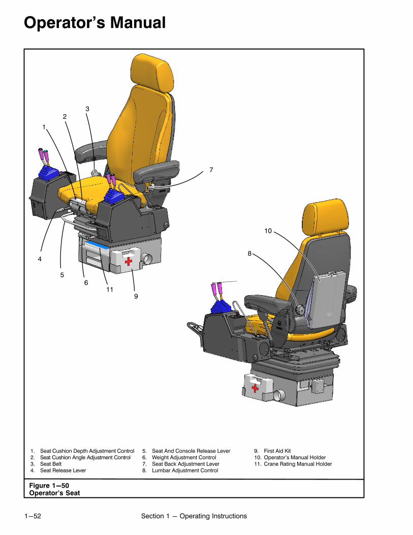
Operator's Manual
1-52 Section 1 - Operating Instructions
1. Seat Cushion Depth Adjustment Control2. Seat Cushion Angle Adjustment Control3. Seat Belt4. Seat Release Lever
5. Seat And Console Release Lever6. Weight Adjustment Control7. Seat Back Adjustment Lever8. Lumbar Adjustment Control
9. First Aid Kit10. Operator's Manual Holder11. Crane Rating Manual Holder
Figure 1-50Operator's Seat
23
4
56
9
7
8
10
1
11
Operator's Manual
1-53Section 1 - Operating Instructions
Operator's SeatThis 6‐way adjustable seat is controlled by manualcontrols. Refer to Figure 1-50.
WARNINGDo not make seat or console adjustmentswhile operating the crane or while crane is in
motion. Discontinue operations and properly
park crane before making adjustments.
Seat Height Adjustment
The seat height can be manually adjusted to three positions. With the seat in it's lowest position, grab the seatand pull up until the seat latches in the first detent position. Pull it up again to latch it in the second detent position. Pull it up again and push it down to release theseat to the lowest position.
1. Seat Cushion Depth Adjustment Control
Use the seat cushion depth adjustment control toposition the seat cushion to the desired depth.
2. Seat Cushion Angle Adjustment Control
Use the seat cushion angle adjustment control toposition the seat cushion to the desired angle.
3. Seat Belt
A seat belt is provided and must be worn during alloperations. To fasten the seat belt pull the belt outof the retractor and insert the tongue into thebuckle until you hear a snap and feel the latch engage. Ensure the belt is not twisted and is fittingsnugly across the hips, not around the waist.
WARNINGAlways wear the seat belt while operating thecrane. The seat belt must be snug and low
across the hips.
4. Seat Release Lever
Pull the seat release lever up and hold. Position theseat as desired and release the lever to lock theseat in place.
5. Seat And Console Release Lever
Pull the seat and console release lever up andhold. Position the seat and console as desired andrelease the lever to lock the seat and console inplace.
6. Weight Adjustment Control
The weight adjustment control is used to adjust theweight resistance for maximum driver comfort. Increase the weight resistance for a heavier operatoror bumpy travel conditions; decrease for lighter operator or smooth travel conditions.
7. Seat Back Adjustment Lever
Raise the seat back adjustment lever and adjustthe seat back to the desired position. Release theseat back adjustment lever to lock the seat back inplace.
8. Lumbar Adjustment Control
Use the lumbar adjustment control to adjust thelumbar support in the lower back area of the seat.
First Aid KitThe crane has a multi‐purpose first aid kit to the left ofthe operator's seat. Refer to Figure 1-50.
Operator's Manual HolderThe Operator's Manual is stored on the back of the operator's seat. Refer Figure 1-50. This is a convenientstorage place to ensure this Operator's Manual is keptwith the crane at all times. If this Operator's Manualbecomes lost, damaged, or unreadable, it must bereplaced before operating the crane. Informationcontained in this Operator's Manual is important andfailure to follow the information it contains could resultin an accident. A replacement Operator's Manual canbe ordered through your Link‐Belt Distributor.
Crane Rating Manual HolderThe Crane Rating Manual is stored under the operator'sseat. It is tethered to the seat to ensure it is kept with thecrane at all times. If the Crane Rating Manual becomes
lost, damaged, or unreadable, it must be replaced be
fore operating the crane. Information contained in theCrane Rating Manual is important and failure to follow theinformation it contains could result in an accident. A replacement Crane Rating Manual can be ordered throughyour Link‐Belt Distributor. Refer to “Crane Rating ManualAnd Serial Number” in Section 5 of this Operator's Manual for further information.
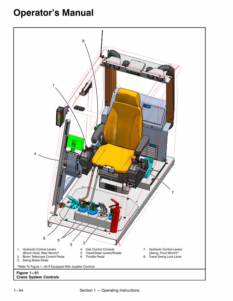
Operator's Manual
1-54 Section 1 - Operating Instructions
1. Hydraulic Control Levers(Boom Hoist, Rear Winch)*
2. Boom Telescope Control Pedal3. Swing Brake Pedal
4. Cab Control Console5. Travel/Steer Levers/Pedals6. Throttle Pedal
7. Hydraulic Control Levers(Swing, Front Winch)*
8. Travel Swing Lock Lever
*Refer To Figure 1-54 If Equipped With Joystick Controls
Figure 1-51Crane System Controls
1
23
4
56
7
8

Operator's Manual
1-55Section 1 - Operating Instructions
Figure 1-52Throttle Lock Controls
1. Up Arrow Button2. Throttle Lock Indicator3. OK Button4. Down Arrow Button
1
2
3
4
Crane System ControlsThe following pages, along with Figure 1-51, give detailed instructions of individual controls related to craneoperation. It is essential that the operator knows thefunction of each control and its duty in the overall operation of the crane.
WARNINGRead and understand all “Operating Safety”procedures as well as all other operating
instructions in this Operator's Manual before
attempting to operate the crane. Operation of
the crane by unqualified personnel may result
in an accident.
Horn ButtonThe horn button is on the right control lever. Refer toFigure 1-48 or Figure 1-54 if equipped with joystickcontrols. To sound the horn, press the button.
Engine Throttle ControlsA foot throttle pedal is on the operator's cab floor. To operate the foot throttle, press down to increase enginespeed; release to decrease engine speed.
Throttle Lock System
The throttle lock system gives the operator the ability toset and hold a specific engine speed. Refer toFigure 1-52 for location of throttle lock controls. Thisprovides the operator with more flexibility for certain jobrequirements.
With the Crane Control Display on the main workingscreen, lock the throttle by pressing the throttle pedaluntil the desired engine speed is reached and pressand release the OK button. The locked indicatorshould illuminate and engine should continue to run ata constant speed when the throttle pedal is released.
To increase throttle lock setting, press and hold the Uparrow button until desired engine speed is reached andrelease switch.
Note: With the throttle locked, the throttle pedal can
still be depressed to increase engine rpm's and willreturn to throttle lock setting when released.
To decrease throttle lock setting, press and hold theDown arrow button until desired engine speed isreached and release switch.
With the Crane Control Display on the main workingscreen, return the engine speed to idle by pressing andreleasing the OK button. The unlocked indicatorshould illuminate.
Note: The throttle lock system is deactivated
anytime the ignition switch is turned off.
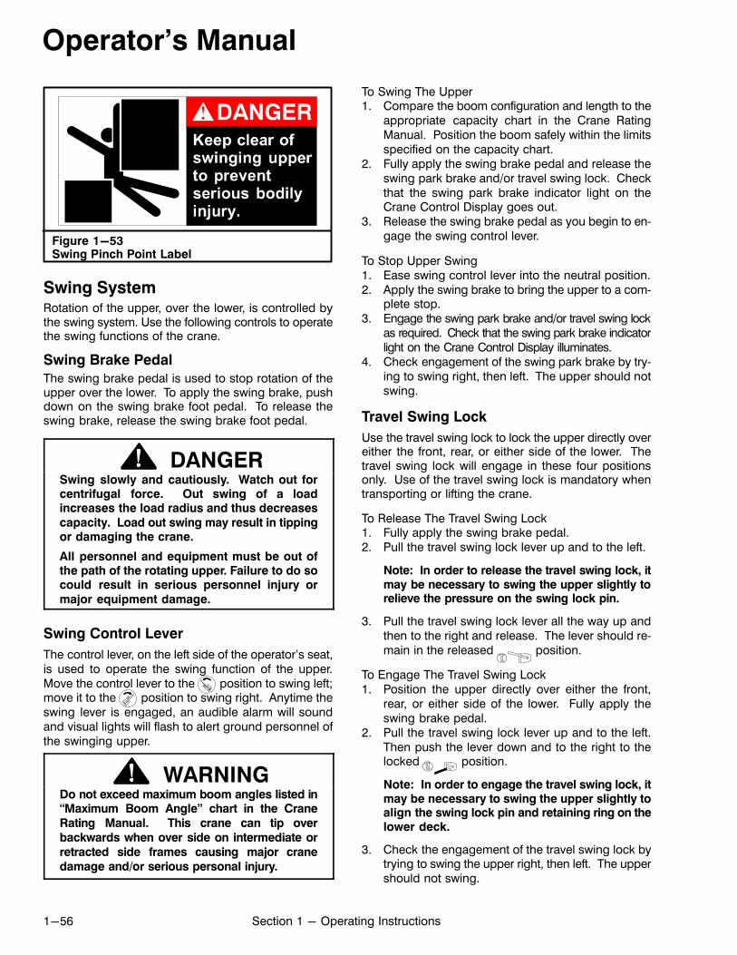
Operator's Manual
1-56 Section 1 - Operating Instructions
Figure 1-53Swing Pinch Point Label
Swing SystemRotation of the upper, over the lower, is controlled bythe swing system. Use the following controls to operatethe swing functions of the crane.
Swing Brake Pedal
The swing brake pedal is used to stop rotation of theupper over the lower. To apply the swing brake, pushdown on the swing brake foot pedal. To release theswing brake, release the swing brake foot pedal.
DANGERSwing slowly and cautiously. Watch out forcentrifugal force. Out swing of a loadincreases the load radius and thus decreases
capacity. Load out swing may result in tippingor damaging the crane.
All personnel and equipment must be out ofthe path of the rotating upper. Failure to do socould result in serious personnel injury or
major equipment damage.
Swing Control Lever
The control lever, on the left side of the operator's seat,is used to operate the swing function of the upper.Move the control lever to the position to swing left;move it to the position to swing right. Anytime theswing lever is engaged, an audible alarm will soundand visual lights will flash to alert ground personnel ofthe swinging upper.
WARNINGDo not exceed maximum boom angles listed in“Maximum Boom Angle” chart in the Crane
Rating Manual. This crane can tip over
backwards when over side on intermediate or
retracted side frames causing major crane
damage and/or serious personal injury.
To Swing The Upper1. Compare the boom configuration and length to the
appropriate capacity chart in the Crane RatingManual. Position the boom safely within the limitsspecified on the capacity chart.
2. Fully apply the swing brake pedal and release theswing park brake and/or travel swing lock. Checkthat the swing park brake indicator light on theCrane Control Display goes out.
3. Release the swing brake pedal as you begin to engage the swing control lever.
To Stop Upper Swing1. Ease swing control lever into the neutral position.2. Apply the swing brake to bring the upper to a com
plete stop.3. Engage the swing park brake and/or travel swing lock
as required. Check that the swing park brake indicatorlight on the Crane Control Display illuminates.
4. Check engagement of the swing park brake by trying to swing right, then left. The upper should notswing.
Travel Swing Lock
Use the travel swing lock to lock the upper directly overeither the front, rear, or either side of the lower. Thetravel swing lock will engage in these four positionsonly. Use of the travel swing lock is mandatory whentransporting or lifting the crane.
To Release The Travel Swing Lock1. Fully apply the swing brake pedal.2. Pull the travel swing lock lever up and to the left.
Note: In order to release the travel swing lock, itmay be necessary to swing the upper slightly torelieve the pressure on the swing lock pin.
3. Pull the travel swing lock lever all the way up andthen to the right and release. The lever should remain in the released position.
To Engage The Travel Swing Lock1. Position the upper directly over either the front,
rear, or either side of the lower. Fully apply theswing brake pedal.
2. Pull the travel swing lock lever up and to the left.Then push the lever down and to the right to thelocked position.
Note: In order to engage the travel swing lock, itmay be necessary to swing the upper slightly toalign the swing lock pin and retaining ring on thelower deck.
3. Check the engagement of the travel swing lock bytrying to swing the upper right, then left. The uppershould not swing.
Operator's Manual
1-57Section 1 - Operating Instructions
Swing Park Brake
The swing park brake is a multiple disc type brake andis used for holding the upper, in any position, over thelower during normal crane operations. An indicatorlight on the Crane Control Display will illuminate whenthe swing park brake is applied. For switch location,refer to Figure 1-48 or Figure 1-54 if equipped withjoystick controls.
To Release The Swing Park Brake1. Fully apply the swing brake pedal.2. Push the swing park brake switch on the left con
trol lever. The indicator light will go out.
To Apply The Swing Park Brake1. Rotate the upper to the desired position over the
lower. Apply the swing brake pedal to bring the upper to a complete stop.
2. Push the swing park brake switch on the left control lever. Indicator light will illuminate.
CAUTIONDo not attempt to apply swing park brake withthe upper in motion. This practice will result in
damage to the swing mechanism. Use the
swing brake pedal to stop rotation of upper.
3. Check engagement of swing park brake by trying toswing upper right, then left. Upper should not swing.
Wire Rope Winch SystemThis system controls raising and lowering the winchwire rope(s). The system is equipped with a two speedmotor that, when activated, will approximately doublewinch wire rope(s) speed. The controls for the systemare shown in Figure 1-48, Figure 1-51, and/orFigure 1-54 if equipped with joystick controls. Reviewthe following for control descriptions and a brief summary of operation.
WARNINGCold weather operation of the winch requiresa warm‐up procedure. Failure to properlywarm‐up the winch may result in brakeslippage. Warm‐up the winch beforebeginning crane operations.
Warm‐Up Procedure
A warm‐up procedure is recommended at eachstart‐up and is essential at ambient temperaturesbelow 40°F (4°C ). Allow the engine to run at idle speedand the winch control lever(s) in neutral for severalminutes. Once the hydraulic oil begins to warm,
operate the winch at low speed, with no load, lifting andlowering only the hook block or hook ball until warm oilcirculates throughout the winch.
WARNINGThe weight of the load must be known beforemaking a lift. Compare the load weight to the
appropriate capacity chart in the Crane Rating
Manual to ensure compliance with capacity
ratings. Compare the load weight to the Wire
Rope Capacity Chart in the Crane Rating
Manual to determine the number of parts ofline required to lift the load. Rig and set up the
crane to ensure compliance with both the
appropriate crane capacity chart and Wire
Rope Capacity Chart in the Crane Rating
Manual. Properly set the Rated CapacityLimiter to the correct crane configuration.
Do not lift a load to the point where the hook
block, hook ball, or load contacts the head
machinery. “Two blocking” could damage the
hook block, hook ball, and/or the headmachinery. Always keep the hook block, hook
ball, and load a safe distance from the boom.
Front Winch Control Lever (If Equipped)
This lever controls the front winch drum. Pull this control lever back to the position to lift the load. Pushthis control lever forward to the position to lowerthe load. Refer to “Winch Operation” in this Section ofthis Operator's Manual for more specific instructions.
Rear Winch Control Lever
This lever controls the rear winch drum. Pull this control lever back to the position to lift the load. Pushthis control lever forward to the position to lowerthe load. Refer to “Winch Operation” in this Section ofthis Operator's Manual for more specific instructions.
Winch Operation
The following is a brief description of the basic procedure for operating the wire rope winch. Crane operations are to be performed only by a qualified operatorwho has read and fully understands the entire contentof this Operator's Manual.
To Lift A Load: Position head machinery directly abovethe load. Attach the hook block or hook ball to the load.Pull the control lever back, toward the operator.
Note: When both winch levers are activated simul
taneously, the winch line requiring the most line pull
may not function.
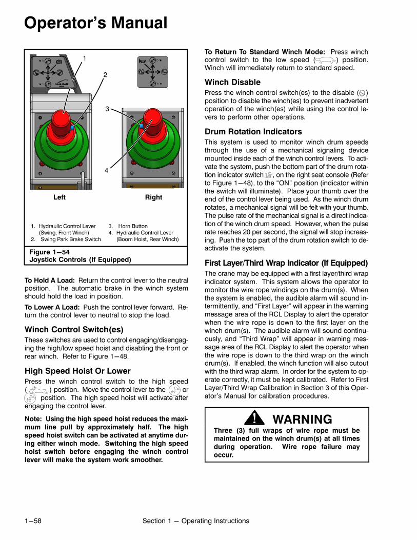
Operator's Manual
1-58 Section 1 - Operating Instructions
Figure 1-54Joystick Controls (If Equipped)
1. Hydraulic Control Lever(Swing, Front Winch)
2. Swing Park Brake Switch
3. Horn Button4. Hydraulic Control Lever
(Boom Hoist, Rear Winch)
1
4
Left Right
2
3
To Hold A Load: Return the control lever to the neutralposition. The automatic brake in the winch systemshould hold the load in position.
To Lower A Load: Push the control lever forward. Return the control lever to neutral to stop the load.
Winch Control Switch(es)
These switches are used to control engaging/disengaging the high/low speed hoist and disabling the front orrear winch. Refer to Figure 1-48.
High Speed Hoist Or Lower
Press the winch control switch to the high speed(� �) position. Move the control lever to the or
position. The high speed hoist will activate afterengaging the control lever.
Note: Using the high speed hoist reduces the maxi
mum line pull by approximately half. The high
speed hoist switch can be activated at anytime dur
ing either winch mode. Switching the high speed
hoist switch before engaging the winch control
lever will make the system work smoother.
To Return To Standard Winch Mode: Press winchcontrol switch to the low speed ( ) position.Winch will immediately return to standard speed.
Winch Disable
Press the winch control switch(es) to the disable ( )position to disable the winch(es) to prevent inadvertentoperation of the winch(es) while using the control levers to perform other operations.
Drum Rotation Indicators
This system is used to monitor winch drum speedsthrough the use of a mechanical signaling devicemounted inside each of the winch control levers. To activate the system, push the bottom part of the drum rotation indicator switch , on the right seat console (Referto Figure 1-48), to the “ON” position (indicator withinthe switch will illuminate). Place your thumb over theend of the control lever being used. As the winch drumrotates, a mechanical signal will be felt with your thumb.The pulse rate of the mechanical signal is a direct indication of the winch drum speed. However, when the pulserate reaches 20 per second, the signal will stop increasing. Push the top part of the drum rotation switch to deactivate the system.
First Layer/Third Wrap Indicator (If Equipped)
The crane may be equipped with a first layer/third wrapindicator system. This system allows the operator tomonitor the wire rope windings on the drum(s). Whenthe system is enabled, the audible alarm will sound intermittently, and “First Layer” will appear in the warningmessage area of the RCL Display to alert the operatorwhen the wire rope is down to the first layer on thewinch drum(s). The audible alarm will sound continuously, and “Third Wrap” will appear in warning message area of the RCL Display to alert the operator whenthe wire rope is down to the third wrap on the winchdrum(s). If enabled, the winch function will also cutoutwith the third wrap alarm. In order for the system to operate correctly, it must be kept calibrated. Refer to FirstLayer/Third Wrap Calibration in Section 3 of this Operator's Manual for calibration procedures.
WARNINGThree (3) full wraps of wire rope must bemaintained on the winch drum(s) at all times
during operation. Wire rope failure may
occur.
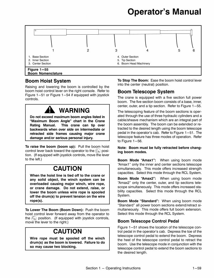
Operator's Manual
1-59Section 1 - Operating Instructions
Figure 1-55Boom Nomenclature
1. Base Section2. Inner Section3. Center Section
4. Outer Section5. Tip Section6. Boom Head Machinery
65421 3
Boom Hoist SystemRaising and lowering the boom is controlled by theboom hoist control lever on the right console. Refer toFigure 1-51 or Figure 1-54 if equipped with joystickcontrols.
WARNINGDo not exceed maximum boom angles listed in“Maximum Boom Angle” chart in the Crane
Rating Manual. This crane can tip over
backwards when over side on intermediate or
retracted side frames causing major crane
damage and/or serious personal injury.
To raise the boom (boom up): Pull the boom hoistcontrol lever back toward the operator to the position. (If equipped with joystick controls, move the leverto the left.)
CAUTIONWhen the hoist line is tied off to the crane orany solid object, the winch system can be
overloaded causing major winch, wire rope,
or crane damage. Do not extend, raise, or
lower the boom unless wire rope is spooled
off the drum(s) to prevent tension on the wire
rope(s).
To Lower The Boom (Boom Down): Push the boomhoist control lever forward away from the operator tothe position. (If equipped with joystick controls,move the lever to the right.)
CAUTIONWire rope must be spooled off the winchdrum(s) as the boom is lowered. Failure to do
so may cause two blocking.
To Stop The Boom: Ease the boom hoist control leverinto the center (neutral) position.
Boom Telescope SystemThe crane is equipped with a five section full powerboom. The five section boom consists of a base, inner,center, outer, and a tip section. Refer to Figure 1-55.
The telescoping feature of the boom sections is operated through the use of three hydraulic cylinders and acable/sheave mechanism which are an integral part ofthe boom assembly. The boom can be extended or retracted to the desired length using the boom telescopepedal in the operator's cab. Refer to Figure 1-51. Thetelescope feature has three modes of operation. Referto Figure 1-56.
Note: Boom must be fully retracted before chang
ing boom modes.
Boom Mode “Amax1”: When using boom mode“Amax1” only the inner and center sections telescopesimultaneously. This mode offers increased strengthcapacities. Select this mode through the RCL System.
Boom Mode “Amax2”: When using boom mode“Amax2” only the center, outer, and tip sections telescope simultaneously. This mode offers increased stability capacities. Select this mode through the RCLSystem.
Boom Mode “Standard”: When using boom mode“Standard” all power boom sections extend/retract simultaneously. This mode offers full boom extension.Select this mode through the RCL System.
Boom Telescope Control Pedal
Figure 1-51 shows the location of the telescope control pedal in the operator's cab. Depress the toe of thetelescope control pedal to extend the boom. Depressthe heel of the telescope control pedal to retract theboom. Use the telescope mode in conjunction with thetelescope control pedal to extend the boom sections tothe desired length.
Operator's Manual
1-60 Section 1 - Operating Instructions
Boom Telescope Override Switches
Boom telescope override switches are provided tomanually override the telescope system if the boom isnot extending/retracting proportionally. Theseswitches are to be used for that purpose only. Pressthe switch to enter telescope override mode. For allboom modes, move the switch to one of the threepositions to override its corresponding boom sectionso the boom can be extended/retracted proportionally.Refer to Figure 1-48 for switch location. Each positionof the switch is defined as follows:
Top position of the switch will override the innerand center sections allowing only the tip and outer sections to extend and retract.
Center position of the switch will override the inner, outer, and tip sections allowing only the center section to extend and retract.
The bottom position of the switch will override thecenter, outer, and tip sections allowing only the inner section to extend and retract.
To Extend The Boom Sections1. Park the crane on a firm level surface.2. Review the appropriate capacity chart in the Crane
Rating Manual to establish boom length, angle,and load limitations.
Note: Boom must be fully retracted before
changing boom modes.
3. Set the RCL System to the desired telescopemode.
CAUTIONWhen the hoist line is tied off to the crane orany solid object, the winch system can be
overloaded causing major winch, wire rope,
or crane damage. Do not extend boom, raise
or lower the boom, or raise the crane on
outriggers unless wire rope is spooled off the
drum (s) to prevent tension on the wire
rope(s).
4. Depress the toe of the telescope control pedal.
CAUTIONWire rope must be spooled off the winchdrum(s) as the boom is extended. Failure to
do so may cause two blocking.
5. Stop the boom sections by releasing the telescopecontrol pedal.
Note: The telescope control pedal is spring
loaded and should return to the neutral position
when released.
To Retract The Boom Sections
1. Depress the heel of the telescope control pedal.2. Stop the boom sections by releasing the telescope
control pedal.

Operator's Manual
1-61Section 1 - Operating Instructions
Figure 1-56Boom Telescope Modes
Boom Mode “Amax1”
Boom Mode “Amax2”
Inner (T1) and center (T2) sections telescope simultaneously.
Center (T2), outer (T3), and tip (T4) sections telescope simultaneously.
Boom Mode “Standard”Inner (T1), center (T2), outer (T3), and tip (T4) sections telescope simultaneously.
Base
400000502.52.52.52.5605.05.05.05.0707.57.57.57.58010.010.010.010.09012.512.512.512.510015.015.015.015.011017.517.517.517.512020.020.020.020.013022.522.522.522.514025.025.025.025.015027.527.527.527.5
InnerCenterOuterTip
40000503.33606.667010.008013.339016.6610020.0011023.33
122.527.50
BaseCenterOuterTip
3.336.6610.0013.3316.6620.0023.3327.50
3.336.6610.0013.3316.6620.0023.3327.50
400505.06010.07015.08020.09025.09527.5
BaseInnerCenter
05.010.015.020.025.027.5
Boom Length (Ft.)Telescope Length (Ft.)
Boom Length (Ft.)Telescope Length (Ft.)
Boom Length (Ft.)Telescope Length (Ft.)
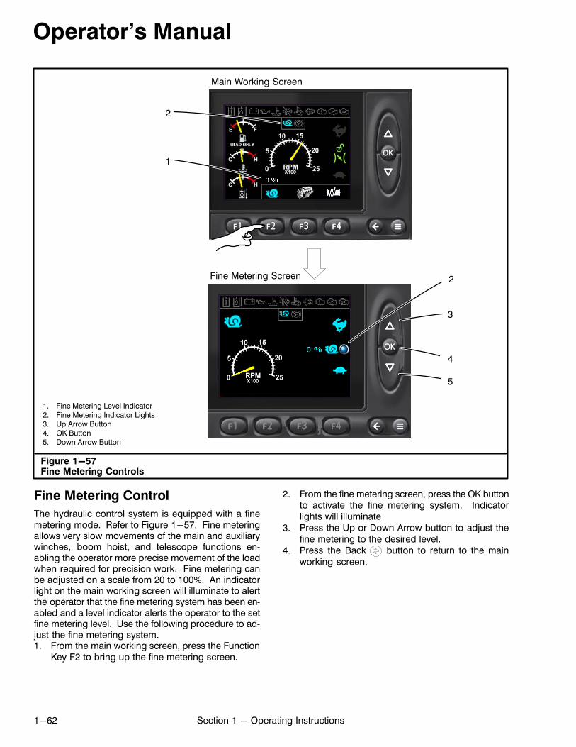
Operator's Manual
1-62 Section 1 - Operating Instructions
Figure 1-57Fine Metering Controls
1. Fine Metering Level Indicator2. Fine Metering Indicator Lights3. Up Arrow Button4. OK Button5. Down Arrow Button
3
2
4
5
1
Main Working Screen
Fine Metering Screen 2
Fine Metering Control
The hydraulic control system is equipped with a finemetering mode. Refer to Figure 1-57. Fine meteringallows very slow movements of the main and auxiliarywinches, boom hoist, and telescope functions enabling the operator more precise movement of the loadwhen required for precision work. Fine metering canbe adjusted on a scale from 20 to 100%. An indicatorlight on the main working screen will illuminate to alertthe operator that the fine metering system has been enabled and a level indicator alerts the operator to the setfine metering level. Use the following procedure to adjust the fine metering system.1. From the main working screen, press the Function
Key F2 to bring up the fine metering screen.
2. From the fine metering screen, press the OK buttonto activate the fine metering system. Indicatorlights will illuminate
3. Press the Up or Down Arrow button to adjust thefine metering to the desired level.
4. Press the Back button to return to the mainworking screen.
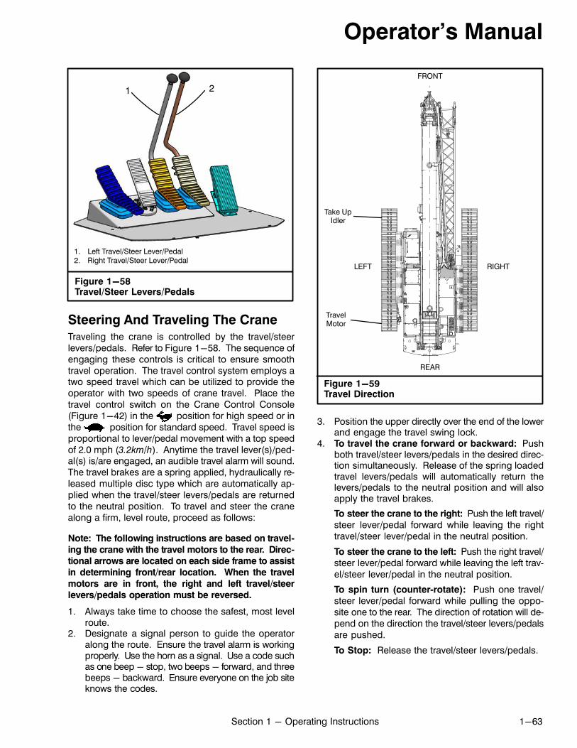
Operator's Manual
1-63Section 1 - Operating Instructions
Figure 1-58Travel/Steer Levers/Pedals
1. Left Travel/Steer Lever/Pedal2. Right Travel/Steer Lever/Pedal
1 2
Steering And Traveling The CraneTraveling the crane is controlled by the travel/steerlevers/pedals. Refer to Figure 1-58. The sequence ofengaging these controls is critical to ensure smoothtravel operation. The travel control system employs atwo speed travel which can be utilized to provide theoperator with two speeds of crane travel. Place thetravel control switch on the Crane Control Console(Figure 1-42) in the position for high speed or inthe position for standard speed. Travel speed isproportional to lever/pedal movement with a top speedof 2.0 mph (3.2km/h). Anytime the travel lever(s)/pedal(s) is/are engaged, an audible travel alarm will sound.The travel brakes are a spring applied, hydraulically released multiple disc type which are automatically applied when the travel/steer levers/pedals are returnedto the neutral position. To travel and steer the cranealong a firm, level route, proceed as follows:
Note: The following instructions are based on travel
ing the crane with the travel motors to the rear. Direc
tional arrows are located on each side frame to assist
in determining front/rear location. When the travel
motors are in front, the right and left travel/steer
levers/pedals operation must be reversed.
1. Always take time to choose the safest, most levelroute.
2. Designate a signal person to guide the operatoralong the route. Ensure the travel alarm is workingproperly. Use the horn as a signal. Use a code suchas one beep - stop, two beeps - forward, and threebeeps - backward. Ensure everyone on the job siteknows the codes.
Figure 1-59Travel Direction
LEFT RIGHT
FRONT
REAR
TravelMotor
Take UpIdler
3. Position the upper directly over the end of the lowerand engage the travel swing lock.
4. To travel the crane forward or backward: Pushboth travel/steer levers/pedals in the desired direction simultaneously. Release of the spring loadedtravel levers/pedals will automatically return thelevers/pedals to the neutral position and will alsoapply the travel brakes.
To steer the crane to the right: Push the left travel/steer lever/pedal forward while leaving the righttravel/steer lever/pedal in the neutral position.
To steer the crane to the left: Push the right travel/steer lever/pedal forward while leaving the left travel/steer lever/pedal in the neutral position.
To spin turn (counter‐rotate): Push one travel/steer lever/pedal forward while pulling the opposite one to the rear. The direction of rotation will depend on the direction the travel/steer levers/pedalsare pushed.
To Stop: Release the travel/steer levers/pedals.
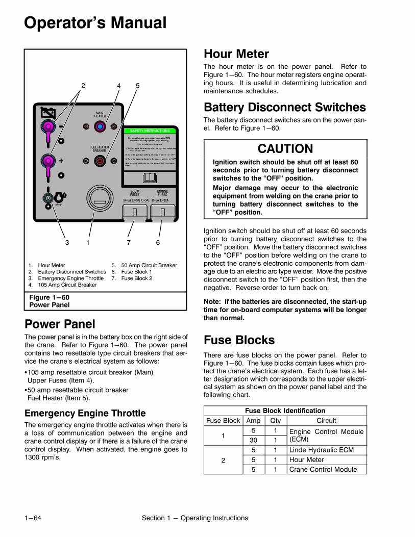
Operator's Manual
1-64 Section 1 - Operating Instructions
FUEL HEATERBREAKER
MAINBREAKER
A-5A
EQUIPFUSES
ENGINEFUSES
- +
B-5A C-5A D-5A E-30An/min
Figure 1-60Power Panel
1. Hour Meter2. Battery Disconnect Switches3. Emergency Engine Throttle4. 105 Amp Circuit Breaker
5. 50 Amp Circuit Breaker6. Fuse Block 17. Fuse Block 2
54
1
2
3 7 6
Power PanelThe power panel is in the battery box on the right side ofthe crane. Refer to Figure 1-60. The power panelcontains two resettable type circuit breakers that service the crane's electrical system as follows:
�105 amp resettable circuit breaker (Main)Upper Fuses (Item 4).
�50 amp resettable circuit breakerFuel Heater (Item 5).
Emergency Engine ThrottleThe emergency engine throttle activates when there isa loss of communication between the engine andcrane control display or if there is a failure of the cranecontrol display. When activated, the engine goes to1300 rpm's.
Hour MeterThe hour meter is on the power panel. Refer toFigure 1-60. The hour meter registers engine operating hours. It is useful in determining lubrication andmaintenance schedules.
Battery Disconnect SwitchesThe battery disconnect switches are on the power panel. Refer to Figure 1-60.
CAUTIONIgnition switch should be shut off at least 60seconds prior to turning battery disconnect
switches to the “OFF” position.
Major damage may occur to the electronic
equipment from welding on the crane prior to
turning battery disconnect switches to the
“OFF” position.
Ignition switch should be shut off at least 60 secondsprior to turning battery disconnect switches to the“OFF” position. Move the battery disconnect switchesto the “OFF” position before welding on the crane toprotect the crane's electronic components from damage due to an electric arc type welder. Move the positivedisconnect switch to the “OFF” position first, then thenegative. Reverse order to turn back on.
Note: If the batteries are disconnected, the start‐up
time for on‐board computer systems will be longer
than normal.
Fuse BlocksThere are fuse blocks on the power panel. Refer toFigure 1-60. The fuse blocks contain fuses which protect the crane's electrical system. Each fuse has a letter designation which corresponds to the upper electrical system as shown on the power panel label and thefollowing chart.
Fuse Block Identification
Fuse Block Amp Qty Circuit
15 1 Engine Control Module
(ECM)30 1
2
5 1 Linde Hydraulic ECM
5 1 Hour Meter
5 1 Crane Control Module

Operator's Manual
1-65Section 1 - Operating Instructions
Figure 1-61Operator's Cab Tilt Control Switch
UP 20�
DOWN
0�
Cab Tilt OperationThe operator's cab tilts up from 0 to 20 degrees abovehorizontal to improve vertical visibility and help to reduce operator fatigue due to neck strain when at highboom angles. Use the three position momentaryswitch on the cab control console to operate the cab tiltfunction. Refer to Figure 1-61.
Cab must be returned to its horizontal, 0 degree position, before exiting the cab. An alarm will sound if theleft arm rest is raised and the cab is tilted above 0 degrees.
Before operating the cab tilt feature, the operator's cabdoor must be secured in the fully closed or fully open position.
Tilting the Upper Operator's Cab
� Push the bottom part of the switch and hold to raisethe cab. Release switch to stop.
� Push the top part of the switch and hold to lower thecab. Release switch to stop.

Operator's Manual
1-66 Section 1 - Operating Instructions
Operating In Wind Or
LightningAvoid working a crane in high winds and when there isa likelihood of lightning. Rated lifting capacities do notaccount for the effects of wind on a suspended load orthe boom. Lifting capacities should be considered acceptable for wind speeds up to 20 mph (32km/h) andappropriately reduced for wind speeds greater than 20mph (32km/h). If you must work in a wind, reduce capacities to those listed in “Wind Restrictions Guide” inthe Crane Rating Manual. Wind blowing against theload and the boom produces a side load on the boomand reduces its capacity. When lifting loads whichhave large surface areas in a wind, such as buildingpanels, the movement of the load may pose a danger
to workers or building structures. Out swing of a loadwill increase the load radius, and may overload thecrane. This could lead to boom failure or the crane tipping. Monitor the wind speed using a wind speed indicator or the “Wind Scale” chart below. Stop lifting operations, ground the load and fully retract and lower theboom to horizontal if wind speed exceeds the maximum allowed listed in “Wind Restrictions Guide” in theCrane Rating Manual. Use the following “Wind Scale”chart as a general guide.
DANGERIf there is a likelihood of lightning,immediately stop lifting operations, ground
the load, and fully retract and lower the boom.
Wind Scale
Wind Speed Wind StrengthInland Wind Effect
mph km/h Beaufort Scale WMO* Description
<0.6 <1 0 Calm Calm, smoke rises vertically.
0.6 to 3.1 1 to 5 1 Light AirSmoke drift indicates wind direction,wind vanes remain still.
3.7 to 6.8 6 to 11 2 Light BreezeWind felt on face, leaves rustle, windvanes begin to move.
7.4 to 11.8 12 to 19 3 Gentle BreezeLeaves and small twigs constantlymoving, light flags extended.
12.4 to 17.4 20 to 28 4 Moderate BreezeDust, leaves, and loose paper lifted,small tree branches move.
18.0 to 23.6 29 to 38 5 Fresh BreezeSmall trees in leaf begin to sway.Crested waves form on inland waters.
24.2 to 30.4 39 to 49 6 Strong BreezeLarger tree branches moving. Telephone wires whistle. Umbrellasused with difficulty.
31.1 to 37.9 50 to 61 7 Near GaleWhole trees moving. Resistance feltwalking against wind.
38.5 to 46.0 62 to 74 8 GaleBreaks twigs off trees. Resistancefelt walking against wind.
46.6 to 54.1 75 to 87 9 Strong GaleSlight structural damage. Slateblows off roofs.
54.7 to 62.8 88 to 101 10 StormTrees broken or uprooted. Considerable structural damage.
* World Meteorological Organization

Operator's Manual
1-67Section 1 - Operating Instructions
1. Anemometer2. Transmitter3. Lock Pin
Figure 1-62Wind Speed Indicator
1
2
Main Boom Fly BaseFly Tip
3
10 Ft Fly Base
RCL Display
Crane Monitoring SystemA crane monitoring system is used for monitoringboom length, boom angle, load weight, and two blocksituations.
Wind Speed Indicator
The crane is equipped with a wireless wind speedindicator integrated into the Rated Capacity LimiterSystem. The indicator is used to monitor wind speedsat the main boom head or the fly head when erected.Refer to Figure 1-62. An anemometer mounted on theboom or fly head transmits wind speed data to the
display unit in the operator's cab. Refer to “WindRestrictions Guide” in the Crane Rating Manual formore information on wind speed restrictions.
CAUTIONRemove the anemometer assembly from theboom and/or fly head during transport toprevent damage to the unit.
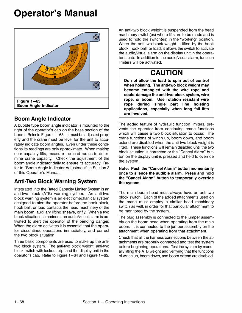
Operator's Manual
1-68 Section 1 - Operating Instructions
Figure 1-63Boom Angle Indicator
Boom Angle IndicatorA bubble type boom angle indicator is mounted to theright of the operator's cab on the base section of theboom. Refer to Figure 1-63. It must be adjusted properly and the crane must be level for the unit to accurately indicate boom angles. Even under these conditions its readings are only approximate. When makingnear capacity lifts, measure the load radius to determine crane capacity. Check the adjustment of theboom angle indicator daily to ensure its accuracy. Refer to “Boom Angle Indicator Adjustment” in Section 3of this Operator's Manual.
Anti‐Two Block Warning System
Integrated into the Rated Capacity Limiter System is ananti‐two block (ATB) warning system. An anti‐twoblock warning system is an electromechanical systemdesigned to alert the operator before the hook block,hook ball, or load contacts the head machinery of themain boom, auxiliary lifting sheave, or fly. When a twoblock situation is imminent, an audio/visual alarm is activated to alert the operator of the pending danger.When the alarm activates it is essential that the operator discontinue operations immediately, and correctthe two block situation.
Three basic components are used to make up the anti‐two block system. The anti‐two block weight, anti‐twoblock switch with lockout clip, and the display unit in theoperator's cab. Refer to Figure 1-64 and Figure 1-65.
An anti‐two block weight is suspended from the headmachinery switch(es) where lifts are to be made and isused to hold the switch(es) in the “working” position.When the anti‐two block weight is lifted by the hookblock, hook ball, or load, it allows the switch to activatethe audio/visual alarm on the display unit in the operator's cab. In addition to the audio/visual alarm, functionlimiters will be activated.
CAUTIONDo not allow the load to spin out of controlwhen hoisting. The anti‐two block weight may
become entangled with the wire rope and
could damage the anti‐two block system, wire
rope, or boom. Use rotation resistant wire
rope during single part line hoisting
applications, especially when long fall lifts
are involved.
The added feature of hydraulic function limiters, prevents the operator from continuing crane functionswhich will cause a two block situation to occur. Thecrane functions of winch up, boom down, and boomextend are disabled when the anti‐two block weight islifted. These functions will remain disabled until the twoblock situation is corrected or the “Cancel Alarm” button on the display unit is pressed and held to overridethe system.
Note: Push the “Cancel Alarm” button momentarily
once to silence the audible alarm. Press and hold
the “Cancel Alarm” button to temporarily override
the system.
The main boom head must always have an anti‐twoblock switch. Each of the added attachments used onthe crane must employ a similar head machineryswitch as well, in order for that particular attachment tobe monitored by the system.
The plug assembly is connected to the jumper assembly on the boom head when operating from the mainboom. It is connected to the jumper assembly on theattachment when operating from that attachment.
Check that all the harness connections between the attachments are properly connected and test the systembefore beginning operations. Test the system by manually lifting the ATB weight and verifying that the functionsof winch up, boom down, and boom extend are disabled.
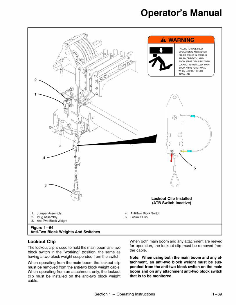
Operator's Manual
1-69Section 1 - Operating Instructions
Figure 1-64Anti‐Two Block Weights And Switches
1. Jumper Assembly2. Plug Assembly3. Anti‐Two Block Weight
4. Anti‐Two Block Switch5. Lockout Clip
Lockout Clip Installed(ATB Switch Inactive)
3
2
1
WARNINGFAILURE TO HAVE FULLY
OPERATIONAL ATB SYSTEM
COULD RESULT IN SERIOUS
INJURY OR DEATH. MAIN
BOOM ATB IS DISABLED WHEN
LOCKOUT IS INSTALLED. MAIN
BOOM ATB IS FUNCTIONAL
WHEN LOCKOUT IS NOT
INSTALLED.
4
5
Lockout Clip
The lockout clip is used to hold the main boom anti‐twoblock switch in the “working” position, the same ashaving a two block weight suspended from the switch.
When operating from the main boom the lockout clipmust be removed from the anti‐two block weight cable.When operating from an attachment only, the lockoutclip must be installed on the anti‐two block weightcable.
When both main boom and any attachment are reevedfor operation, the lockout clip must be removed fromthe cable.
Note: When using both the main boom and any at
tachment, an anti‐two block weight must be sus
pended from the anti‐two block switch on the main
boom and on any attachment anti‐two block switch
that is to be monitored.

Operator's Manual
1-70 Section 1 - Operating Instructions
Figure 1-65Rated Capacity Limiter
1. Bar‐Graph2. Pre‐Alarm Indicator3. Overload Indicator4. Side Frame Or Lifting Jack Configuration5. Counterweight Configuration6. Boom Extension Mode7. Attachment Configuration8. Stowed Attachment Configuration9. Operator Alarm Indicator10. Cancel Alarm Icon
11. Brightness Icon12. Winch Setup Icon13. Selection Buttons14. Winch Select Icon15. Main Menu Icon16. Crane Representation Image17. Wind Speed Display18. Boom Telescope Animation Display19. Boom Length Display
20. Boom Section Length Display21. Working Area Display22. Parts Of Line Display23. Warning Message Area24. Load Radius Display25. Boom Angle Display26. Maximum Rated Capacity Display27. Actual Load Display28. Boom Head Height Display
1
13
5
6
8
15
3
2
14
17
12 11
10
9
18
7
4
16
23
19
25
24
27
22
21
20
28
26
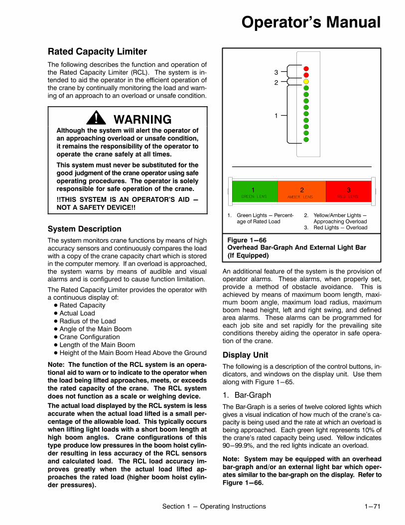
Operator's Manual
1-71Section 1 - Operating Instructions
Rated Capacity Limiter
The following describes the function and operation ofthe Rated Capacity Limiter (RCL). The system is intended to aid the operator in the efficient operation ofthe crane by continually monitoring the load and warning of an approach to an overload or unsafe condition.
WARNINGAlthough the system will alert the operator ofan approaching overload or unsafe condition,
it remains the responsibility of the operator to
operate the crane safely at all times.
This system must never be substituted for the
good judgment of the crane operator using safe
operating procedures. The operator is solelyresponsible for safe operation of the crane.
!!THIS SYSTEM IS AN OPERATOR'S AID -
NOT A SAFETY DEVICE!!
System Description
The system monitors crane functions by means of highaccuracy sensors and continuously compares the loadwith a copy of the crane capacity chart which is storedin the computer memory. If an overload is approached,the system warns by means of audible and visualalarms and is configured to cause function limitation.
The Rated Capacity Limiter provides the operator witha continuous display of:� Rated Capacity� Actual Load� Radius of the Load� Angle of the Main Boom� Crane Configuration� Length of the Main Boom� Height of the Main Boom Head Above the Ground
Note: The function of the RCL system is an opera
tional aid to warn or to indicate to the operator whenthe load being lifted approaches, meets, or exceeds
the rated capacity of the crane. The RCL system
does not function as a scale or weighing device.
The actual load displayed by the RCL system is less
accurate when the actual load lifted is a small per
centage of the allowable load. This typically occurswhen lifting light loads with a short boom length at
high boom angles. Crane configurations of this
type produce low pressures in the boom hoist cylin
der resulting in less accuracy of the RCL sensors
and calculated load. The RCL load accuracy im
proves greatly when the actual load lifted ap
proaches the rated load (higher boom hoist cylinder pressures).
Figure 1-66Overhead Bar‐Graph And External Light Bar
(If Equipped)
2
3
1. Green Lights - Percentage of Rated Load
2. Yellow/Amber Lights -Approaching Overload
3. Red Lights - Overload
1
2 31
An additional feature of the system is the provision ofoperator alarms. These alarms, when properly set,provide a method of obstacle avoidance. This isachieved by means of maximum boom length, maximum boom angle, maximum load radius, maximumboom head height, left and right swing, and definedarea alarms. These alarms can be programmed foreach job site and set rapidly for the prevailing siteconditions thereby aiding the operator in safe operation of the crane.
Display Unit
The following is a description of the control buttons, indicators, and windows on the display unit. Use themalong with Figure 1-65.
1. Bar‐Graph
The Bar‐Graph is a series of twelve colored lights whichgives a visual indication of how much of the crane's capacity is being used and the rate at which an overload isbeing approached. Each green light represents 10% ofthe crane's rated capacity being used. Yellow indicates90-99.9%, and the red lights indicate an overload.
Note: System may be equipped with an overhead
bar‐graph and/or an external light bar which operates similar to the bar‐graph on the display. Refer to
Figure 1-66.
Operator's Manual
1-72 Section 1 - Operating Instructions
2. Pre‐Alarm Indicator
The Pre‐Alarm Indicator illuminates yellow at a pre‐setvalue of 90% of Maximum Rated Capacity and providesa visual indication of an approach to an overload.
3. Overload Indicator
The Overload Indicator illuminates red at a pre‐set value of 100% of the Maximum Rated Capacity and provides a visual indication of Maximum Allowed Load. Itwill also illuminate whenever a wire rope limit is exceeded. Function limiters will occur simultaneously for anOverload, Wire Rope Limit, or a Two Block condition,but function limiters will not occur when exceeding anoperator settable alarm. An audible alarm will soundand a message will appear in the warning messagearea for all 4 conditions.
4. Side Frame Or Lifting Jack Configuration
This area displays the current lower configuration. Itwill also display rigging and travel modes.
5. Counterweight Configuration
This area displays the current counterweight configuration.
6. Boom Extension Mode
This area displays the current boom extension mode. Italso shows the maximum boom length for the currentboom extension mode.
7. Attachment Configuration
This area displays the current attachment configuration.
8. Stowed Attachment Configuration
This area displays the current stowed attachment configuration.
9. Operator Alarm Indicator
This indicator will display whether or not an operatoralarm is set.
10. Cancel Alarm Icon
The button below this icon can be pushed once to silence the audible alarm when the alarm has occurredas a result of either an Overload, a Two Block, or anOperator Settable alarm. It is also used to reset thefunction limit relay when it is necessary to by‐pass afunction limit which has occurred as a result of either anOverload or a Two Block alarm. This requires the button be pressed and held for 2 seconds or longer.
11. Brightness Icon
The button below this icon is used to adjust the displaybrightness.
12. Winch Setup Icon
The button below this icon is used to enter the activewinch setup screen. The active winch setup screen allows the user to configure lift point and parts of line forthe active winch.
13. Selection Buttons
The selection buttons are used to activate each of theicons at the bottom of the screen. The icons willchange depending on the current menu display.
14. Winch Select Icon
The button below this icon is used to select whichwinch will be in use.
15. Main Menu Icon
The button below this icon navigates to the main menu.The main menu contains items such as: Crane Configuration, Operator Alarms, Diagnostics, Display Options, About, etc.
16. Crane Representation Image
This crane representation image is a generic representation of the boom, active winch configuration, auxiliary head configuration (on or off), and fly configuration(on or off). The attachment image will not change withinstalled attachment.
17. Wind Speed Display
The current wind speed is displayed here.
18. Boom Telescope Animation Display
The Boom Telescope Animation Display is a real‐timevisual representation of the location of the boom sections.
19. Boom Length Display
The Boom Length Display gives a continuous indication of the boom length in feet (m). It is the distancefrom the centerline of the boom foot pin to the centerline of the boom head machinery.
Operator's Manual
1-73Section 1 - Operating Instructions
20. Boom Section Length Display
The Boom Section Length Display shows the currentsection lengths as a percentage of their absolute maximum length (not in the current boom mode). The maximum length for each section in the current boommode is shown in brackets.
21. Working Area Display
This area displays a graphical representation of the allowable lifting quadrant(s) based on the selected configuration. A quadrant not allowed will be filled red, anallowable quadrant will be filled green.
22. Parts Of Line Display
The Parts of Line Display shows the parts of line currently selected for the winch in use.
23. Warning Message Area
The Warning Message Area displays text messages ofvarious alarms which may occur during normal operation of the system. When an alarm occurs, the rectangular area fills in red. The Warning Message Area willonly be shown when there is an active message.Otherwise the navigation button icons will be shown.Refer to Figure 1-68. Press any of the selection buttons, except the cancel alarm button, to temporarily replace the Warning Message Area with the navigationicons.
24. Load Radius Display
The Load Radius Display gives a continuous indicationof the radius of the load in feet (m). It is the horizontaldistance from the centerline of rotation to the centerlineof the hook.
25. Boom Angle Display
The Boom Angle Display gives a continuous indicationof the angle of the main boom relative to horizontal.
26. Maximum Rated Capacity Display
The Maximum Rated Capacity Display is a digital display of the maximum permitted capacity. It is derivedfrom a copy of the crane's capacity chart which isstored in the computer memory and is the referencecapacity for any lifting operation. It is dependent on theconfiguration currently selected, which is shown in thecrane configuration screen, and which determines thesection of the capacity chart to be used as the rated capacity reference.
27. Actual Load Display
The Actual Load Display is a digital display of the totalload suspended below the boom or fly head. It includes the load, any slings, pins, or tackle used to secure the load and the hook block or hook ball.
28. Boom Head Height Display
The Boom Head Height Display gives a continuous display of the height of the boom head or attachment headabove the ground.
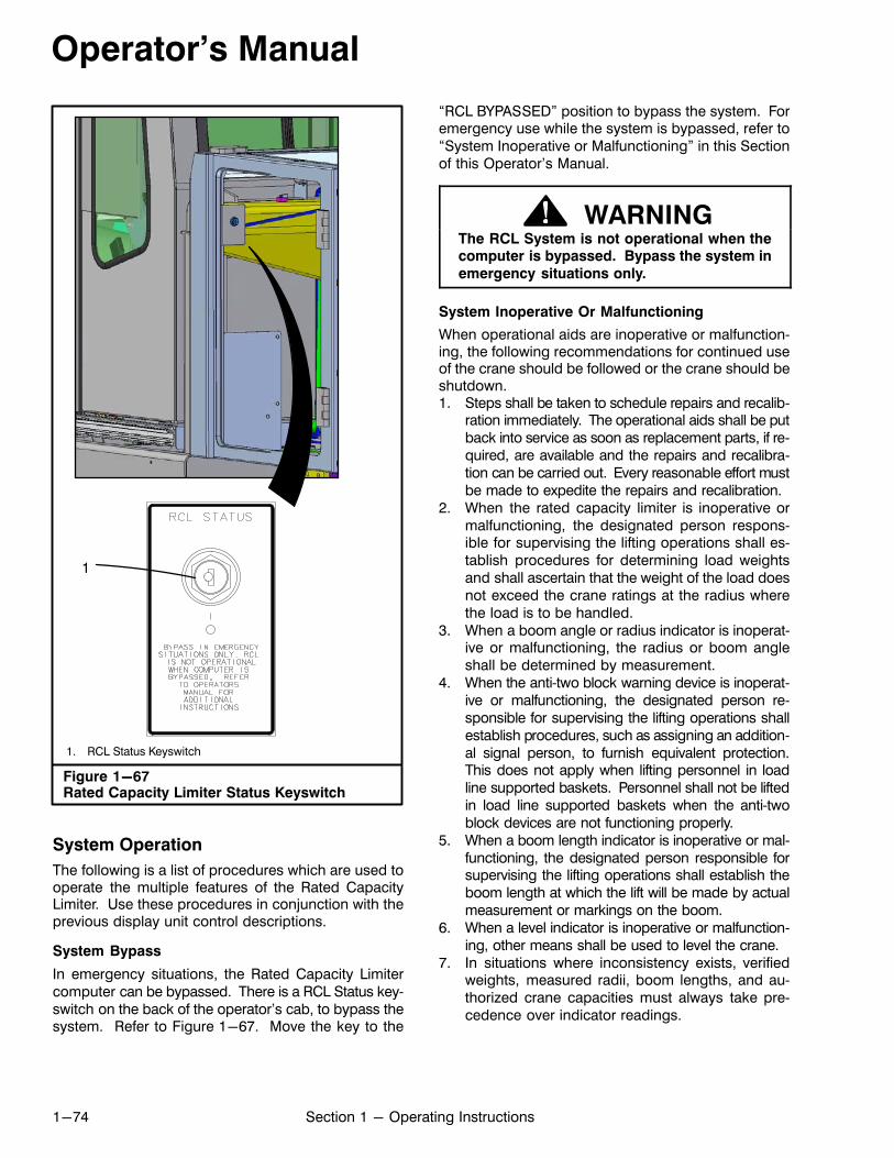
Operator's Manual
1-74 Section 1 - Operating Instructions
Figure 1-67Rated Capacity Limiter Status Keyswitch
1. RCL Status Keyswitch
1
System Operation
The following is a list of procedures which are used tooperate the multiple features of the Rated CapacityLimiter. Use these procedures in conjunction with theprevious display unit control descriptions.
System Bypass
In emergency situations, the Rated Capacity Limitercomputer can be bypassed. There is a RCL Status keyswitch on the back of the operator's cab, to bypass thesystem. Refer to Figure 1-67. Move the key to the
“RCL BYPASSED” position to bypass the system. Foremergency use while the system is bypassed, refer to“System Inoperative or Malfunctioning” in this Sectionof this Operator's Manual.
WARNINGThe RCL System is not operational when thecomputer is bypassed. Bypass the system in
emergency situations only.
System Inoperative Or Malfunctioning
When operational aids are inoperative or malfunctioning, the following recommendations for continued useof the crane should be followed or the crane should beshutdown.1. Steps shall be taken to schedule repairs and recalib
ration immediately. The operational aids shall be putback into service as soon as replacement parts, if required, are available and the repairs and recalibration can be carried out. Every reasonable effort mustbe made to expedite the repairs and recalibration.
2. When the rated capacity limiter is inoperative ormalfunctioning, the designated person responsible for supervising the lifting operations shall establish procedures for determining load weightsand shall ascertain that the weight of the load doesnot exceed the crane ratings at the radius wherethe load is to be handled.
3. When a boom angle or radius indicator is inoperative or malfunctioning, the radius or boom angleshall be determined by measurement.
4. When the anti‐two block warning device is inoperative or malfunctioning, the designated person responsible for supervising the lifting operations shallestablish procedures, such as assigning an additional signal person, to furnish equivalent protection.This does not apply when lifting personnel in loadline supported baskets. Personnel shall not be liftedin load line supported baskets when the anti‐twoblock devices are not functioning properly.
5. When a boom length indicator is inoperative or malfunctioning, the designated person responsible forsupervising the lifting operations shall establish theboom length at which the lift will be made by actualmeasurement or markings on the boom.
6. When a level indicator is inoperative or malfunctioning, other means shall be used to level the crane.
7. In situations where inconsistency exists, verifiedweights, measured radii, boom lengths, and authorized crane capacities must always take precedence over indicator readings.
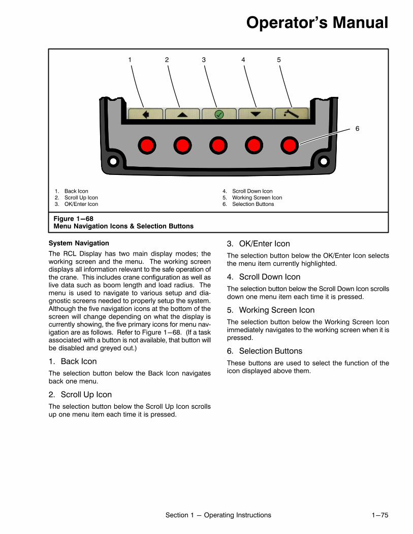
Operator's Manual
1-75Section 1 - Operating Instructions
1. Back Icon2. Scroll Up Icon3. OK/Enter Icon
4. Scroll Down Icon5. Working Screen Icon6. Selection Buttons
Figure 1-68Menu Navigation Icons & Selection Buttons
4 5
6
1 2 3
System Navigation
The RCL Display has two main display modes; theworking screen and the menu. The working screendisplays all information relevant to the safe operation ofthe crane. This includes crane configuration as well aslive data such as boom length and load radius. Themenu is used to navigate to various setup and diagnostic screens needed to properly setup the system.Although the five navigation icons at the bottom of thescreen will change depending on what the display iscurrently showing, the five primary icons for menu navigation are as follows. Refer to Figure 1-68. (If a taskassociated with a button is not available, that button willbe disabled and greyed out.)
1. Back Icon
The selection button below the Back Icon navigatesback one menu.
2. Scroll Up Icon
The selection button below the Scroll Up Icon scrollsup one menu item each time it is pressed.
3. OK/Enter Icon
The selection button below the OK/Enter Icon selectsthe menu item currently highlighted.
4. Scroll Down Icon
The selection button below the Scroll Down Icon scrollsdown one menu item each time it is pressed.
5. Working Screen Icon
The selection button below the Working Screen Iconimmediately navigates to the working screen when it ispressed.
6. Selection Buttons
These buttons are used to select the function of theicon displayed above them.
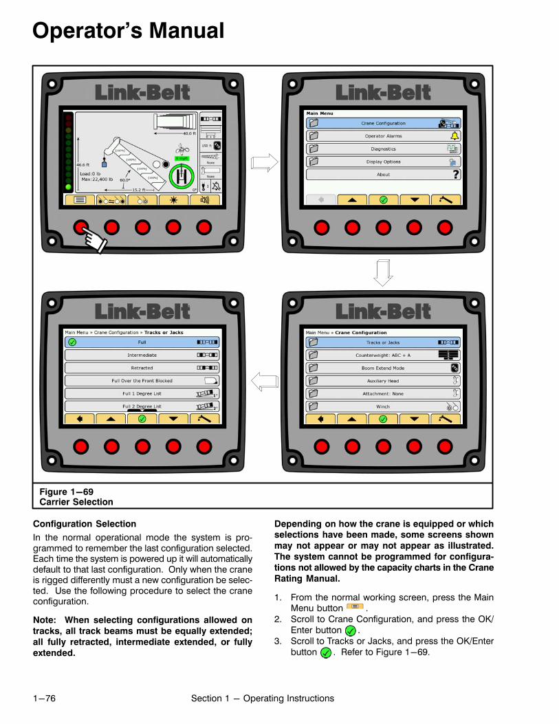
Operator's Manual
1-76 Section 1 - Operating Instructions
Figure 1-69Carrier Selection
Configuration Selection
In the normal operational mode the system is programmed to remember the last configuration selected.Each time the system is powered up it will automaticallydefault to that last configuration. Only when the craneis rigged differently must a new configuration be selected. Use the following procedure to select the craneconfiguration.
Note: When selecting configurations allowed on
tracks, all track beams must be equally extended;
all fully retracted, intermediate extended, or fully
extended.
Depending on how the crane is equipped or whichselections have been made, some screens shown
may not appear or may not appear as illustrated.
The system cannot be programmed for configura
tions not allowed by the capacity charts in the Crane
Rating Manual.
1. From the normal working screen, press the MainMenu button .
2. Scroll to Crane Configuration, and press the OK/Enter button .
3. Scroll to Tracks or Jacks, and press the OK/Enterbutton . Refer to Figure 1-69.
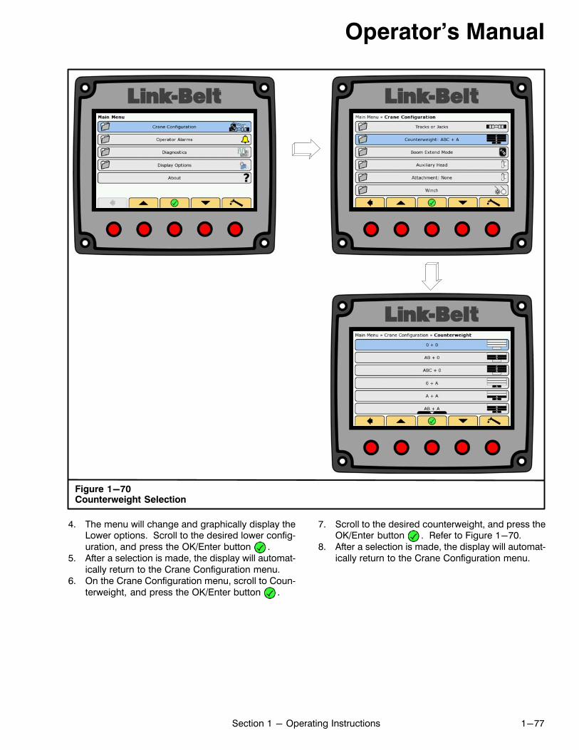
Operator's Manual
1-77Section 1 - Operating Instructions
Figure 1-70Counterweight Selection
4. The menu will change and graphically display theLower options. Scroll to the desired lower configuration, and press the OK/Enter button .
5. After a selection is made, the display will automatically return to the Crane Configuration menu.
6. On the Crane Configuration menu, scroll to Counterweight, and press the OK/Enter button .
7. Scroll to the desired counterweight, and press theOK/Enter button . Refer to Figure 1-70.
8. After a selection is made, the display will automatically return to the Crane Configuration menu.
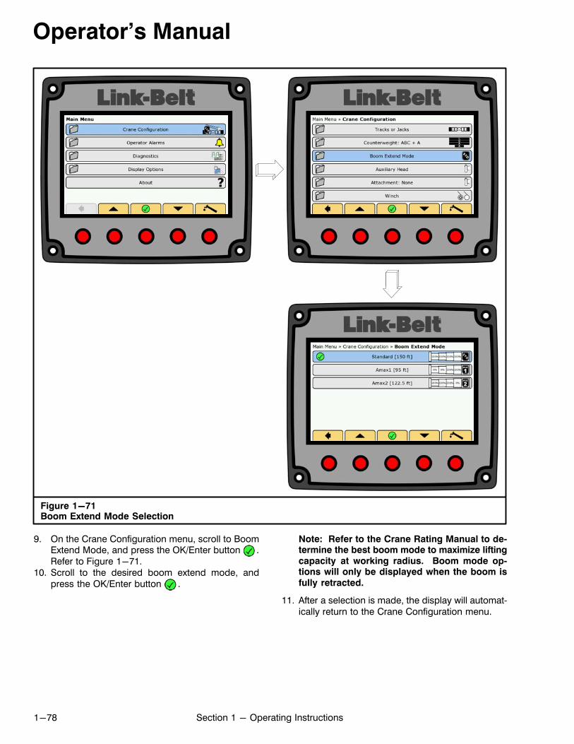
Operator's Manual
1-78 Section 1 - Operating Instructions
Figure 1-71Boom Extend Mode Selection
9. On the Crane Configuration menu, scroll to BoomExtend Mode, and press the OK/Enter button .Refer to Figure 1-71.
10. Scroll to the desired boom extend mode, andpress the OK/Enter button .
Note: Refer to the Crane Rating Manual to determine the best boom mode to maximize liftingcapacity at working radius. Boom mode options will only be displayed when the boom isfully retracted.
11. After a selection is made, the display will automatically return to the Crane Configuration menu.
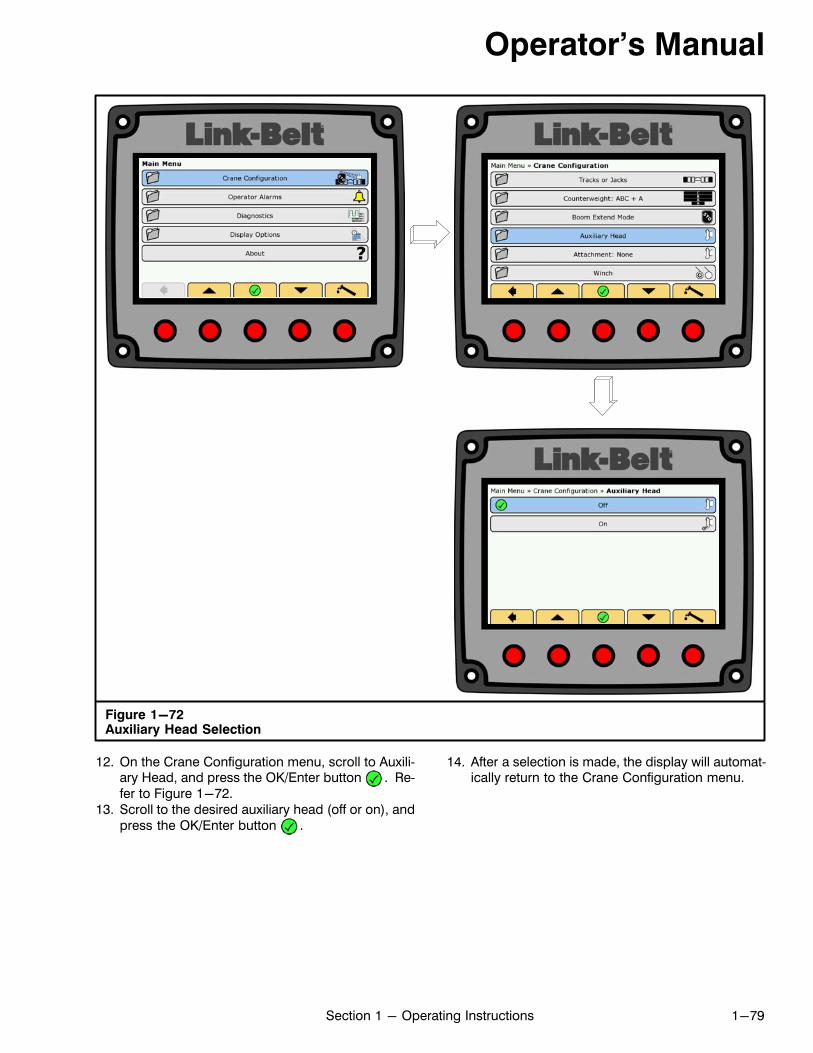
Operator's Manual
1-79Section 1 - Operating Instructions
Figure 1-72Auxiliary Head Selection
12. On the Crane Configuration menu, scroll to Auxiliary Head, and press the OK/Enter button . Refer to Figure 1-72.
13. Scroll to the desired auxiliary head (off or on), andpress the OK/Enter button .
14. After a selection is made, the display will automatically return to the Crane Configuration menu.

Operator's Manual
1-80 Section 1 - Operating Instructions
15. On the Crane Configuration menu, scroll to Attachment, and press the OK/Enter button .
16. Scroll to Erected Attachment, and press the OK/Enter button to display the fly options. Scroll tothe desired erected fly, if required, and press theOK/Enter button . Refer to Figure 1-73.a. If Nothing Erected is selected, the display will
automatically return to the Crane Configuration menu.
b. If an erected attachment is selected, the display will change and graphically display theavailable offsets as required.
c. Scroll to the desired offset angle, and press theOK/Enter button .
d. After a selection is made, the display will automatically return to the Crane Configurationmenu.
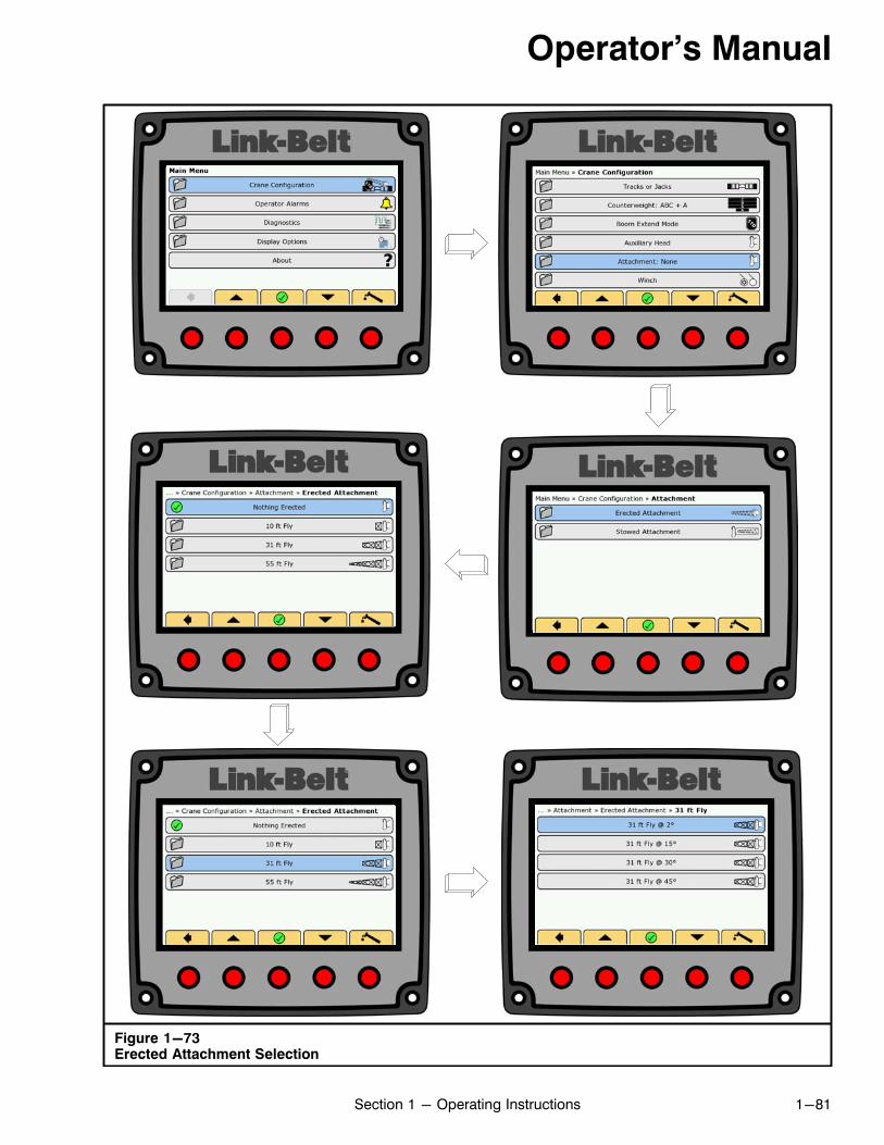
Operator's Manual
1-81Section 1 - Operating Instructions
Figure 1-73Erected Attachment Selection
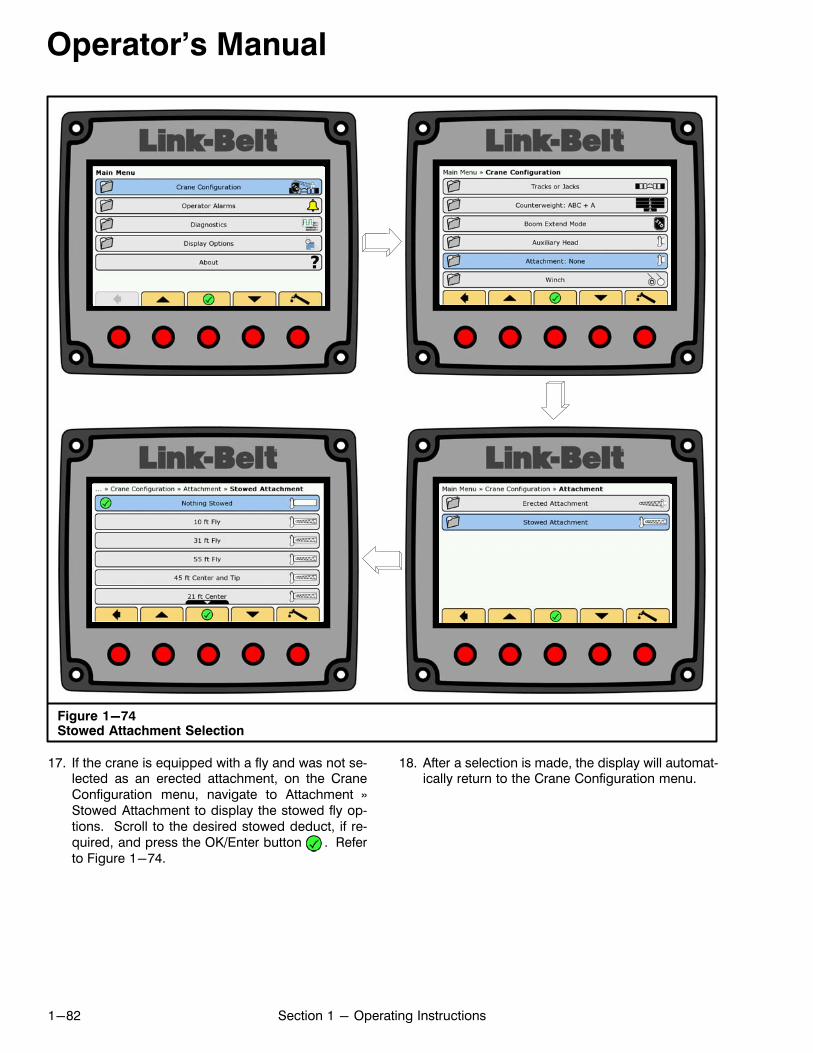
Operator's Manual
1-82 Section 1 - Operating Instructions
Figure 1-74Stowed Attachment Selection
17. If the crane is equipped with a fly and was not selected as an erected attachment, on the CraneConfiguration menu, navigate to Attachment »Stowed Attachment to display the stowed fly options. Scroll to the desired stowed deduct, if required, and press the OK/Enter button . Referto Figure 1-74.
18. After a selection is made, the display will automatically return to the Crane Configuration menu.
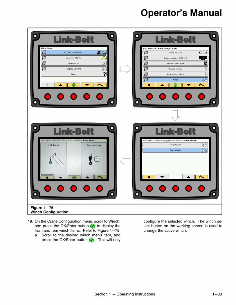
Operator's Manual
1-83Section 1 - Operating Instructions
Figure 1-75Winch Configuration
19. On the Crane Configuration menu, scroll to Winch,and press the OK/Enter button to display thefront and rear winch items. Refer to Figure 1-75.a. Scroll to the desired winch menu item, and
press the OK/Enter button . This will only
configure the selected winch. The winch select button on the working screen is used tochange the active winch.
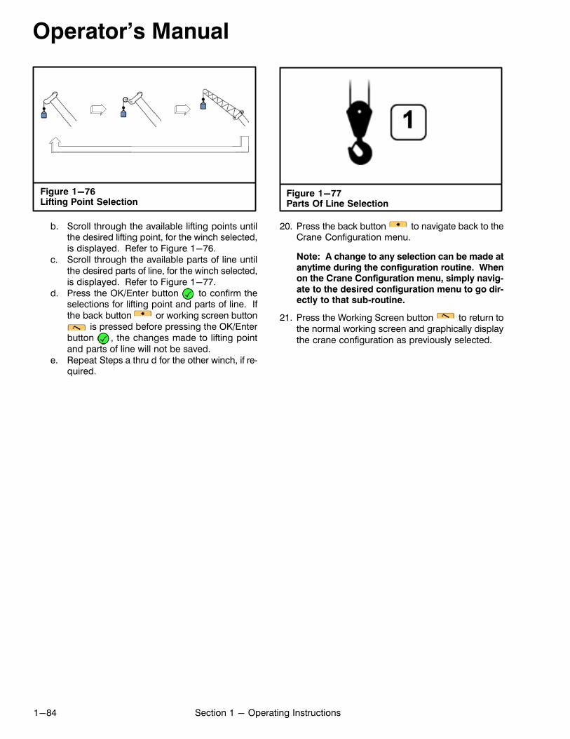
Operator's Manual
1-84 Section 1 - Operating Instructions
Figure 1-76Lifting Point Selection
b. Scroll through the available lifting points untilthe desired lifting point, for the winch selected,is displayed. Refer to Figure 1-76.
c. Scroll through the available parts of line untilthe desired parts of line, for the winch selected,is displayed. Refer to Figure 1-77.
d. Press the OK/Enter button to confirm theselections for lifting point and parts of line. Ifthe back button or working screen button
is pressed before pressing the OK/Enterbutton , the changes made to lifting pointand parts of line will not be saved.
e. Repeat Steps a thru d for the other winch, if required.
Figure 1-77Parts Of Line Selection
20. Press the back button to navigate back to theCrane Configuration menu.
Note: A change to any selection can be made atanytime during the configuration routine. Whenon the Crane Configuration menu, simply navigate to the desired configuration menu to go directly to that sub‐routine.
21. Press the Working Screen button to return tothe normal working screen and graphically displaythe crane configuration as previously selected.
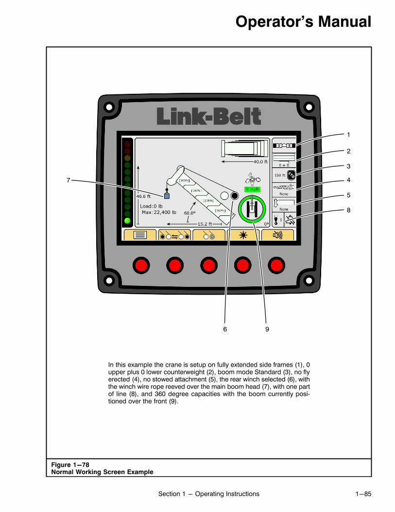
Operator's Manual
1-85Section 1 - Operating Instructions
Figure 1-78Normal Working Screen Example
In this example the crane is setup on fully extended side frames (1), 0upper plus 0 lower counterweight (2), boom mode Standard (3), no flyerected (4), no stowed attachment (5), the rear winch selected (6), withthe winch wire rope reeved over the main boom head (7), with one partof line (8), and 360 degree capacities with the boom currently positioned over the front (9).
1
2
3
4
5
6
7
8
9
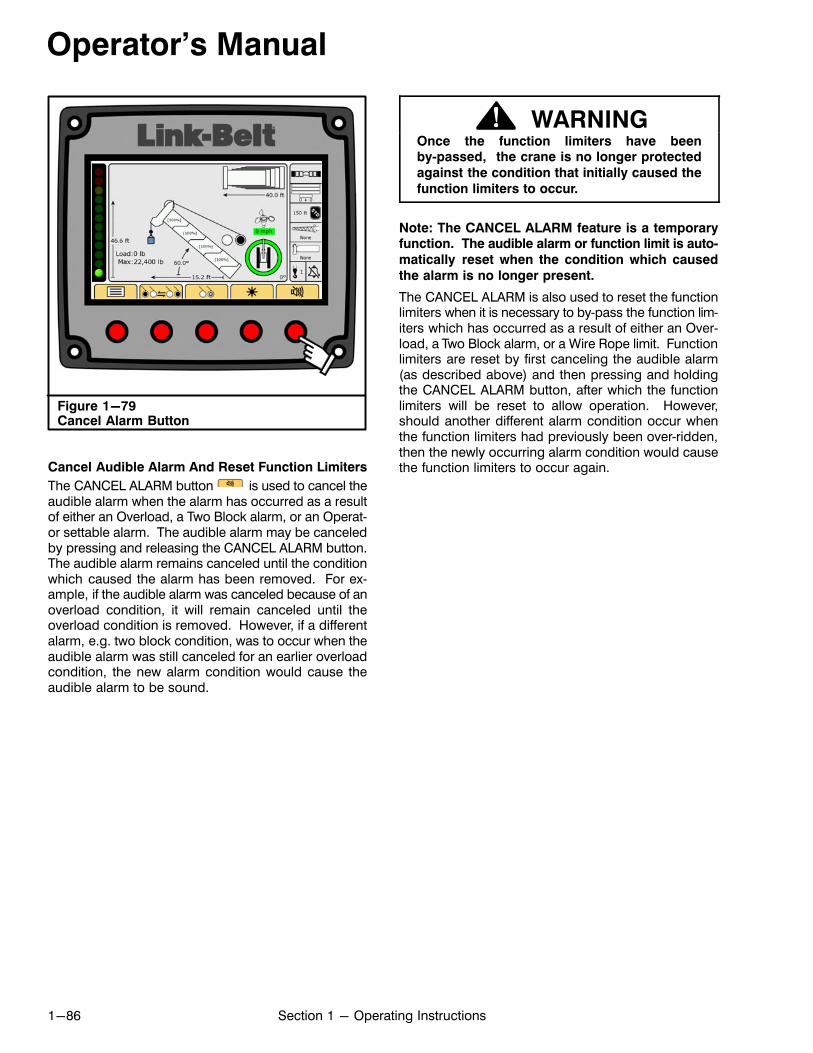
Operator's Manual
1-86 Section 1 - Operating Instructions
Figure 1-79Cancel Alarm Button
Cancel Audible Alarm And Reset Function Limiters
The CANCEL ALARM button is used to cancel theaudible alarm when the alarm has occurred as a resultof either an Overload, a Two Block alarm, or an Operator settable alarm. The audible alarm may be canceledby pressing and releasing the CANCEL ALARM button.The audible alarm remains canceled until the conditionwhich caused the alarm has been removed. For example, if the audible alarm was canceled because of anoverload condition, it will remain canceled until theoverload condition is removed. However, if a differentalarm, e.g. two block condition, was to occur when theaudible alarm was still canceled for an earlier overloadcondition, the new alarm condition would cause theaudible alarm to be sound.
WARNINGOnce the function limiters have beenby‐passed, the crane is no longer protected
against the condition that initially caused the
function limiters to occur.
Note: The CANCEL ALARM feature is a temporaryfunction. The audible alarm or function limit is auto
matically reset when the condition which caused
the alarm is no longer present.
The CANCEL ALARM is also used to reset the functionlimiters when it is necessary to by‐pass the function limiters which has occurred as a result of either an Overload, a Two Block alarm, or a Wire Rope limit. Functionlimiters are reset by first canceling the audible alarm(as described above) and then pressing and holdingthe CANCEL ALARM button, after which the functionlimiters will be reset to allow operation. However,should another different alarm condition occur whenthe function limiters had previously been over‐ridden,then the newly occurring alarm condition would causethe function limiters to occur again.
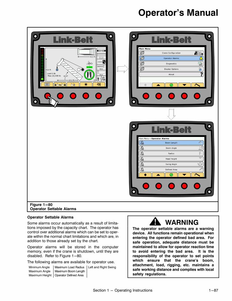
Operator's Manual
1-87Section 1 - Operating Instructions
Figure 1-80Operator Settable Alarms
Operator Settable Alarms
Some alarms occur automatically as a result of limitations imposed by the capacity chart. The operator hascontrol over additional alarms which can be set to operate within the normal chart limitations and which are, inaddition to those already set by the chart.
Operator alarms will be stored in the computermemory, even if the crane is shutdown, until they aredisabled. Refer to Figure 1-80.
The following alarms are available for operator use.
Minimum Angle Maximum Load Radius Left and Right Swing
Maximum Angle Maximum Boom Length
Maximum Height Operator Defined Area
WARNINGThe operator settable alarms are a warningdevice. All functions remain operational when
entering the operator defined bad area. For
safe operation, adequate distance must be
maintained to allow for operator reaction time
to avoid entering the bad area. It is the
responsibility of the operator to set pointswhich ensure that the crane's boom,
attachment, load, rigging, etc. maintains a
safe working distance and complies with local
safety regulations.
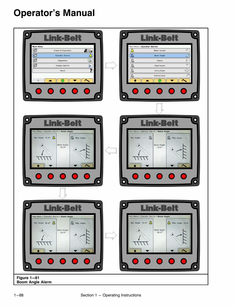
Operator's Manual
1-88 Section 1 - Operating Instructions
Figure 1-81Boom Angle Alarm
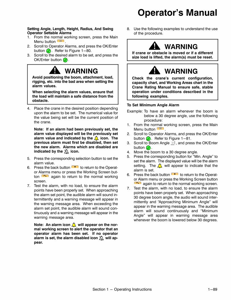
Operator's Manual
1-89Section 1 - Operating Instructions
Setting Angle, Length, Height, Radius, And SwingOperator Settable Alarms1. From the normal working screen, press the Main
Menu button .2. Scroll to Operator Alarms, and press the OK/Enter
button . Refer to Figure 1-80.3. Scroll to the desired alarm to be set, and press the
OK/Enter button .
WARNINGAvoid positioning the boom, attachment, load,rigging, etc. into the bad area when setting thealarm values.
When selecting the alarm values, ensure thatthe load will maintain a safe distance from theobstacle.
4. Place the crane in the desired position dependingupon the alarm to be set. The numerical value forthe value being set will be the current position ofthe crane.
Note: If an alarm had been previously set, thealarm value displayed will be the previously setalarm value and indicated by the icon. Theprevious alarm must first be disabled, then setthe new alarm. Alarms which are disabled areindicated by the icon.
5. Press the corresponding selection button to set thealarm value.
6. Press the back button to return to the Operator Alarms menu or press the Working Screen button again to return to the normal workingscreen.
7. Test the alarm, with no load, to ensure the alarmpoints have been properly set. When approachingthe alarm set point, the audible alarm will sound intermittently and a warning message will appear inthe warning message area. When exceeding thealarm set point, the audible alarm will sound continuously and a warning message will appear in thewarning message area.
Note: An alarm icon will appear on the normal working screen to alert the operator that anoperator alarm has been set. If no operatoralarm is set, the alarm disabled icon will appear.
8. Use the following examples to understand the useof the procedure.
WARNINGIf crane or obstacle is moved or if a differentsize load is lifted, the alarm(s) must be reset.
WARNINGCheck the crane's current configuration,capacity chart, and Working Areas chart in the
Crane Rating Manual to ensure safe, stable
operation under conditions described in the
following examples.
To Set Minimum Angle Alarm
Example: To have an alarm whenever the boom isbelow a 30 degree angle, use the followingprocedure:
1. From the normal working screen, press the MainMenu button .
2. Scroll to Operator Alarms, and press the OK/Enterbutton . Refer to Figure 1-81.
3. Scroll to Boom Angle , and press the OK/Enterbutton .
4. Move the boom to a 30 degree angle.5. Press the corresponding button for “Min. Angle” to
set the alarm. The displayed value will be the alarmsetting. The will appear to indicate that thealarm is set.
6. Press the back button to return to the Operator Alarm menu or press the Working Screen button
again to return to the normal working screen.7. Test the alarm, with no load, to ensure the alarm
points have been properly set. When approaching30 degree boom angle, the audio will sound intermittently and “Approaching Minimum Angle” willappear in the warning message area. The audiblealarm will sound continuously and “MinimumAngle” will appear in warning message areawhenever the boom is lowered below 30 degrees.
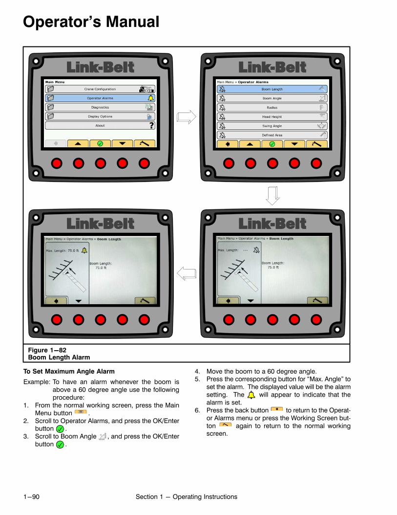
Operator's Manual
1-90 Section 1 - Operating Instructions
Figure 1-82Boom Length Alarm
To Set Maximum Angle Alarm
Example: To have an alarm whenever the boom isabove a 60 degree angle use the followingprocedure:
1. From the normal working screen, press the MainMenu button .
2. Scroll to Operator Alarms, and press the OK/Enterbutton .
3. Scroll to Boom Angle , and press the OK/Enterbutton .
4. Move the boom to a 60 degree angle.5. Press the corresponding button for “Max. Angle” to
set the alarm. The displayed value will be the alarmsetting. The will appear to indicate that thealarm is set.
6. Press the back button to return to the Operator Alarms menu or press the Working Screen button again to return to the normal workingscreen.

Operator's Manual
1-91Section 1 - Operating Instructions
7. Test the alarm, with no load, to ensure the alarmpoints have been properly set. When approaching60 degree boom angle, the audio will sound intermittently and “Approaching Maximum Angle” willappear in the warning message area. The audiblealarm will sound continuously whenever the boomis raised above 60 degrees and “Maximum Angle”will appear in warning message area.
To Set Maximum Length Alarm
Example: To have an alarm whenever the boomlength exceeds 75 feet (22.8m), use thefollowing procedure:
1. From the normal working screen, press the MainMenu button .
2. Scroll to Operator Alarms, and press the OK/Enterbutton .
3. Scroll to Boom Length , and press the OK/Enter
button .
4. Extend the boom so that the length is 75feet(22.8m).
5. Press the corresponding button for “Max. Length”to set the alarm. The displayed value will be thealarm setting. The will appear to indicate thatthe alarm is set.
6. Press the back button to return to the Operator Alarms menu or press the Working Screen button again to return to the normal workingscreen.
7. Test the alarm, with no load, to ensure the alarmpoints have been properly set. When approaching75 foot (22.8m) boom length, the audio alarm willsound intermittently and “Approaching MaximumLength” will appear in the warning message area.The audible alarm will sound continuouslywhenever the boom length exceeds 75 feet(22.8m) and “Maximum Length” will appear in thewarning message area.
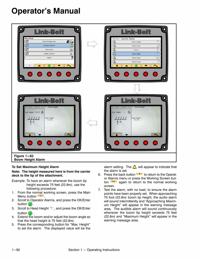
Operator's Manual
1-92 Section 1 - Operating Instructions
Figure 1-83Boom Height Alarm
To Set Maximum Height Alarm
Note: The height measured here is from the carrier
deck to the tip of the attachment.
Example: To have an alarm whenever the boom tipheight exceeds 75 feet (22.8m), use thefollowing procedure:
1. From the normal working screen, press the MainMenu button .
2. Scroll to Operator Alarms, and press the OK/Enterbutton .
3. Scroll to Head Height , and press the OK/Enter
button .4. Extend the boom and/or adjust the boom angle so
that the head height is 75 feet (22.8m).5. Press the corresponding button for “Max. Height”
to set the alarm. The displayed value will be the
alarm setting. The will appear to indicate thatthe alarm is set.
6. Press the back button to return to the Operator Alarms menu or press the Working Screen button again to return to the normal workingscreen.
7. Test the alarm, with no load, to ensure the alarmpoints have been properly set. When approaching75 foot (22.8m) boom tip height, the audio alarmwill sound intermittently and “Approaching Maximum Height” will appear in the warning messagearea. The audible alarm will sound continuouslywhenever the boom tip height exceeds 75 feet(22.8m) and “Maximum Height” will appear in thewarning message area.
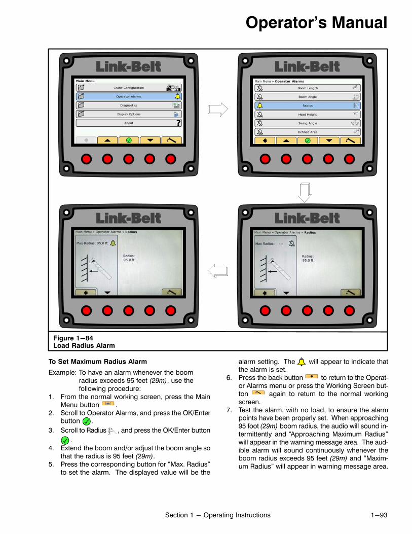
Operator's Manual
1-93Section 1 - Operating Instructions
Figure 1-84Load Radius Alarm
To Set Maximum Radius Alarm
Example: To have an alarm whenever the boomradius exceeds 95 feet (29m), use thefollowing procedure:
1. From the normal working screen, press the MainMenu button .
2. Scroll to Operator Alarms, and press the OK/Enterbutton .
3. Scroll to Radius , and press the OK/Enter button
.4. Extend the boom and/or adjust the boom angle so
that the radius is 95 feet (29m).5. Press the corresponding button for “Max. Radius”
to set the alarm. The displayed value will be the
alarm setting. The will appear to indicate thatthe alarm is set.
6. Press the back button to return to the Operator Alarms menu or press the Working Screen button again to return to the normal workingscreen.
7. Test the alarm, with no load, to ensure the alarmpoints have been properly set. When approaching95 foot (29m) boom radius, the audio will sound intermittently and “Approaching Maximum Radius”will appear in the warning message area. The audible alarm will sound continuously whenever theboom radius exceeds 95 feet (29m) and “Maximum Radius” will appear in warning message area.
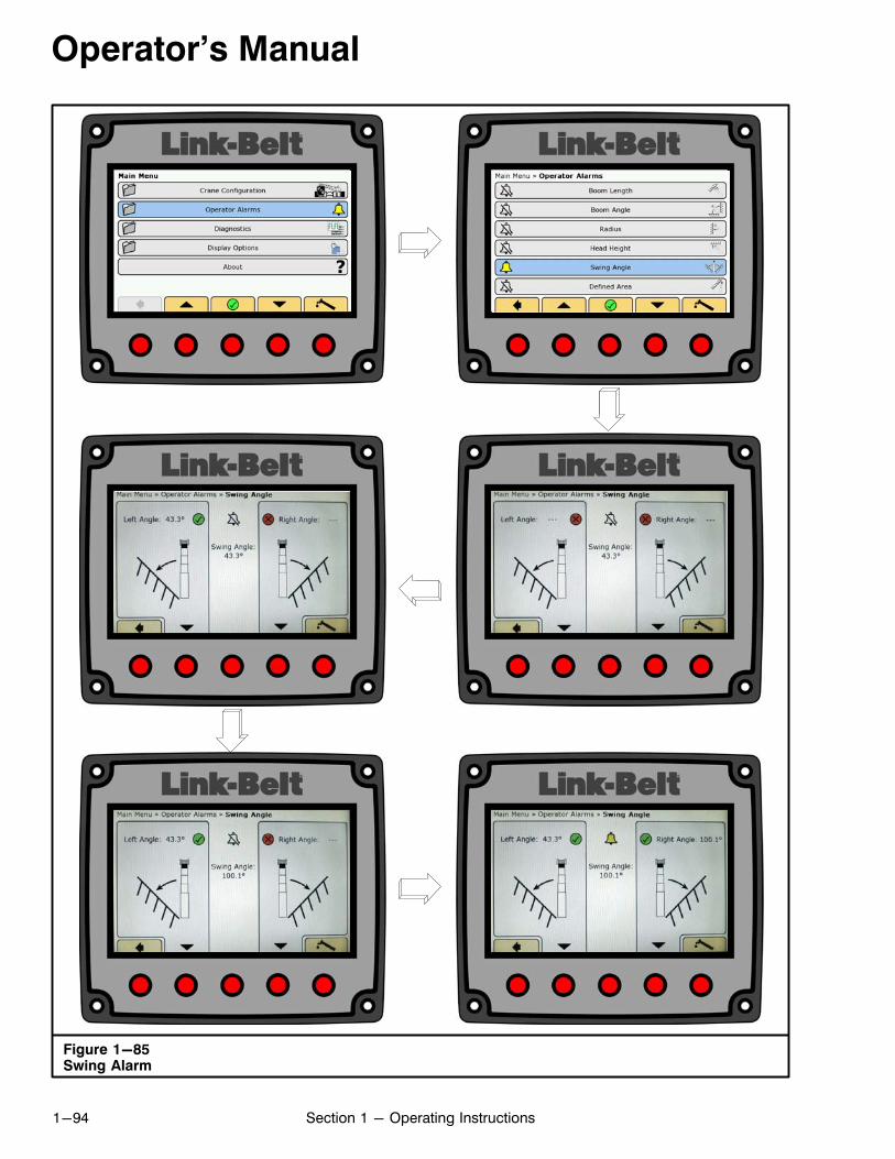
Operator's Manual
1-94 Section 1 - Operating Instructions
Figure 1-85Swing Alarm
Operator's Manual
1-95Section 1 - Operating Instructions
To Set Left And Right Swing Alarms
Example: To have an alarm whenever the LEFTSWING AND RIGHT SWING exceedpre‐determined alarm points, use thefollowing procedure:
1. From the normal working screen, press the MainMenu button .
2. Scroll to Operator Alarms, and press the OK/Enterbutton . Refer to Figure 1-85.
3. Scroll to Swing Angle , and press the OK/Enterbutton .
4. Swing the boom to the left alarm point.5. Press the corresponding button for “Left Angle” to
enter the left alarm point. The displayed value willbe the left alarm setting. The will appear to indicate that the angle is set.
6. Swing the boom to the right alarm point.
7. Press the corresponding button for “Right Angle”to enter the right alarm point. The displayed valuewill be the right alarm setting. The will appear toindicate that the angle is set.
8. When both angles are set, the will appear to indicate that the alarm is set.
9. Press the back button to return to the Operator Alarms menu or press the Working Screen button again to return to the normal workingscreen.
10. Test the alarm, with no load, to ensure the alarmpoints have been properly set. When approachingthe set alarm point, the audio alarm will sound intermittently and “Approaching Swing Angle Limit”will appear in the warning message area. The audible alarm will sound continuously whenever theswing exceeds the alarm points and “Swing AngleLimit” will appear in warning message area.
Note: Both the left and right swing alarms mustbe set for the system to determine the operatorset working area.
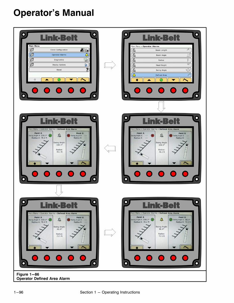
Operator's Manual
1-96 Section 1 - Operating Instructions
Figure 1-86Operator Defined Area Alarm
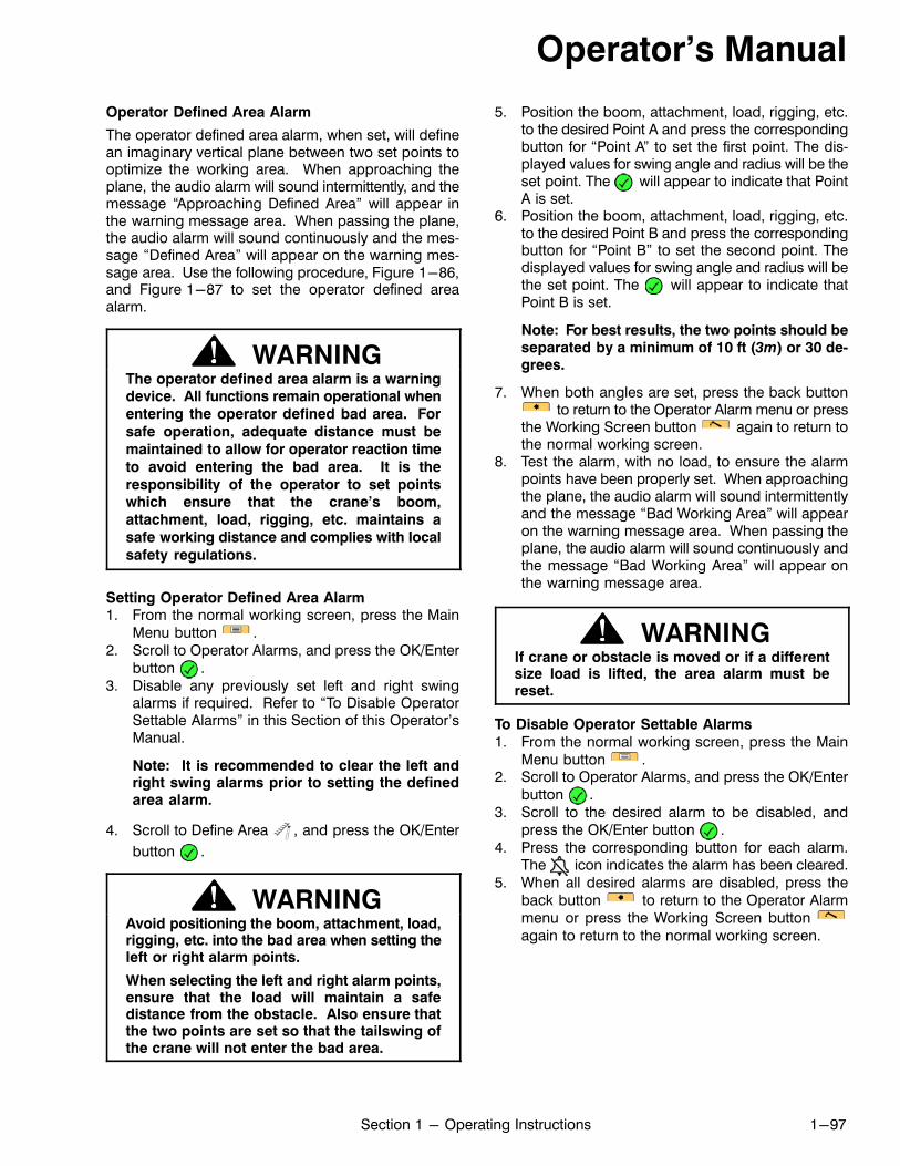
Operator's Manual
1-97Section 1 - Operating Instructions
Operator Defined Area Alarm
The operator defined area alarm, when set, will definean imaginary vertical plane between two set points tooptimize the working area. When approaching theplane, the audio alarm will sound intermittently, and themessage “Approaching Defined Area” will appear inthe warning message area. When passing the plane,the audio alarm will sound continuously and the message “Defined Area” will appear on the warning message area. Use the following procedure, Figure 1-86,and Figure 1-87 to set the operator defined areaalarm.
WARNINGThe operator defined area alarm is a warningdevice. All functions remain operational when
entering the operator defined bad area. For
safe operation, adequate distance must be
maintained to allow for operator reaction time
to avoid entering the bad area. It is the
responsibility of the operator to set pointswhich ensure that the crane's boom,
attachment, load, rigging, etc. maintains a
safe working distance and complies with local
safety regulations.
Setting Operator Defined Area Alarm1. From the normal working screen, press the Main
Menu button .2. Scroll to Operator Alarms, and press the OK/Enter
button .3. Disable any previously set left and right swing
alarms if required. Refer to “To Disable OperatorSettable Alarms” in this Section of this Operator'sManual.
Note: It is recommended to clear the left andright swing alarms prior to setting the definedarea alarm.
4. Scroll to Define Area , and press the OK/Enter
button .
WARNINGAvoid positioning the boom, attachment, load,rigging, etc. into the bad area when setting theleft or right alarm points.
When selecting the left and right alarm points,ensure that the load will maintain a safedistance from the obstacle. Also ensure thatthe two points are set so that the tailswing ofthe crane will not enter the bad area.
5. Position the boom, attachment, load, rigging, etc.to the desired Point A and press the correspondingbutton for “Point A” to set the first point. The displayed values for swing angle and radius will be theset point. The will appear to indicate that PointA is set.
6. Position the boom, attachment, load, rigging, etc.to the desired Point B and press the correspondingbutton for “Point B” to set the second point. Thedisplayed values for swing angle and radius will bethe set point. The will appear to indicate thatPoint B is set.
Note: For best results, the two points should beseparated by a minimum of 10 ft (3m) or 30 degrees.
7. When both angles are set, press the back button to return to the Operator Alarm menu or press
the Working Screen button again to return tothe normal working screen.
8. Test the alarm, with no load, to ensure the alarmpoints have been properly set. When approachingthe plane, the audio alarm will sound intermittentlyand the message “Bad Working Area” will appearon the warning message area. When passing theplane, the audio alarm will sound continuously andthe message “Bad Working Area” will appear onthe warning message area.
WARNINGIf crane or obstacle is moved or if a differentsize load is lifted, the area alarm must bereset.
To Disable Operator Settable Alarms
1. From the normal working screen, press the MainMenu button .
2. Scroll to Operator Alarms, and press the OK/Enterbutton .
3. Scroll to the desired alarm to be disabled, andpress the OK/Enter button .
4. Press the corresponding button for each alarm.The icon indicates the alarm has been cleared.
5. When all desired alarms are disabled, press theback button to return to the Operator Alarmmenu or press the Working Screen button again to return to the normal working screen.
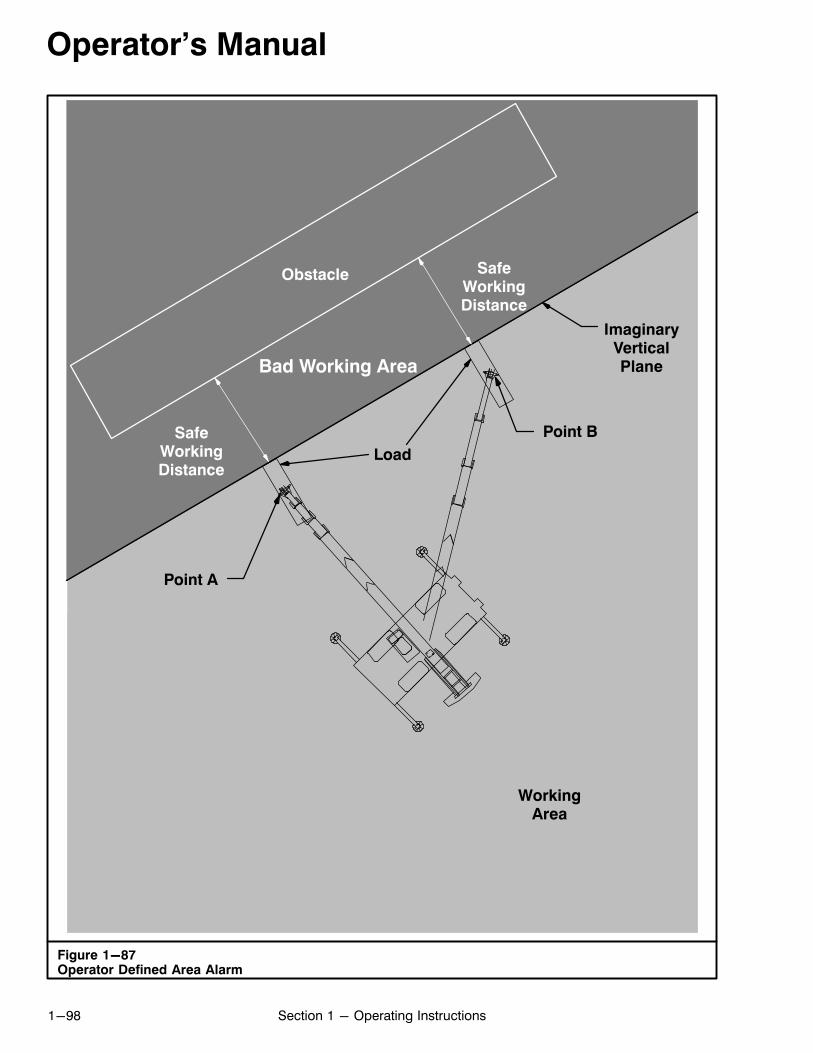
Operator's Manual
1-98 Section 1 - Operating Instructions
Figure 1-87Operator Defined Area Alarm
Point A
Point B
ImaginaryVerticalPlane
Load
SafeWorkingDistance
SafeWorkingDistance
Bad Working Area
Obstacle
WorkingArea
Operator's Manual
1-99Section 1 - Operating Instructions
Figure 1-88Active System Faults
Active System FaultsThe Active System Faults menu displays current system faults. Refer to Figure 1-88 and the System FaultsMessages chart.1. From the normal working screen, press the Main
Menu button .2. Scroll to Diagnostics, and press the OK/Enter but
ton .3. Scroll to Active System Faults, and press the OK/
Enter button .
4. Scroll to the fault code to be addressed, and pressthe OK/Enter button .
5. The message selected, meaning of the message,and how to clear the message will be displayed.
6. Press the back button to return to the SystemFaults menu or press the Working Screen button
to return to the normal working screen.
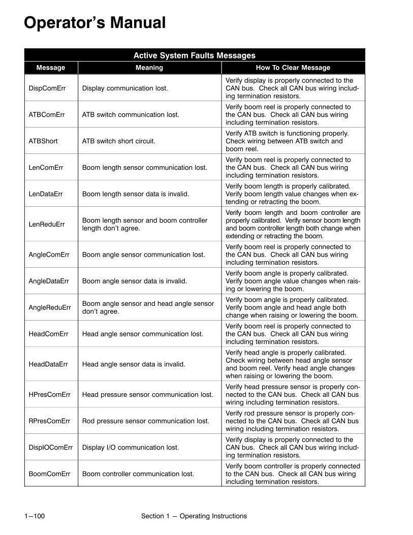
Operator's Manual
1-100 Section 1 - Operating Instructions
Active System Faults Messages
Message Meaning How To Clear Message
DispComErr Display communication lost.Verify display is properly connected to theCAN bus. Check all CAN bus wiring including termination resistors.
ATBComErr ATB switch communication lost.Verify boom reel is properly connected tothe CAN bus. Check all CAN bus wiringincluding termination resistors.
ATBShort ATB switch short circuit.Verify ATB switch is functioning properly.Check wiring between ATB switch andboom reel.
LenComErr Boom length sensor communication lost.Verify boom reel is properly connected tothe CAN bus. Check all CAN bus wiringincluding termination resistors.
LenDataErr Boom length sensor data is invalid.Verify boom length is properly calibrated.Verify boom length value changes when extending or retracting the boom.
LenReduErrBoom length sensor and boom controllerlength don't agree.
Verify boom length and boom controller areproperly calibrated. Verify sensor boom lengthand boom controller length both change whenextending or retracting the boom.
AngleComErr Boom angle sensor communication lost.Verify boom reel is properly connected tothe CAN bus. Check all CAN bus wiringincluding termination resistors.
AngleDataErr Boom angle sensor data is invalid.Verify boom angle is properly calibrated.Verify boom angle value changes when raising or lowering the boom.
AngleReduErrBoom angle sensor and head angle sensordon't agree.
Verify boom angle is properly calibrated.Verify boom angle and head angle bothchange when raising or lowering the boom.
HeadComErr Head angle sensor communication lost.Verify boom reel is properly connected tothe CAN bus. Check all CAN bus wiringincluding termination resistors.
HeadDataErr Head angle sensor data is invalid.
Verify head angle is properly calibrated.Check wiring between head angle sensorand boom reel. Verify head angle changeswhen raising or lowering the boom.
HPresComErr Head pressure sensor communication lost.Verify head pressure sensor is properly connected to the CAN bus. Check all CAN buswiring including termination resistors.
RPresComErr Rod pressure sensor communication lost.Verify rod pressure sensor is properly connected to the CAN bus. Check all CAN buswiring including termination resistors.
DispIOComErr Display I/O communication lost.Verify display is properly connected to theCAN bus. Check all CAN bus wiring including termination resistors.
BoomComErr Boom controller communication lost.Verify boom controller is properly connectedto the CAN bus. Check all CAN bus wiringincluding termination resistors.
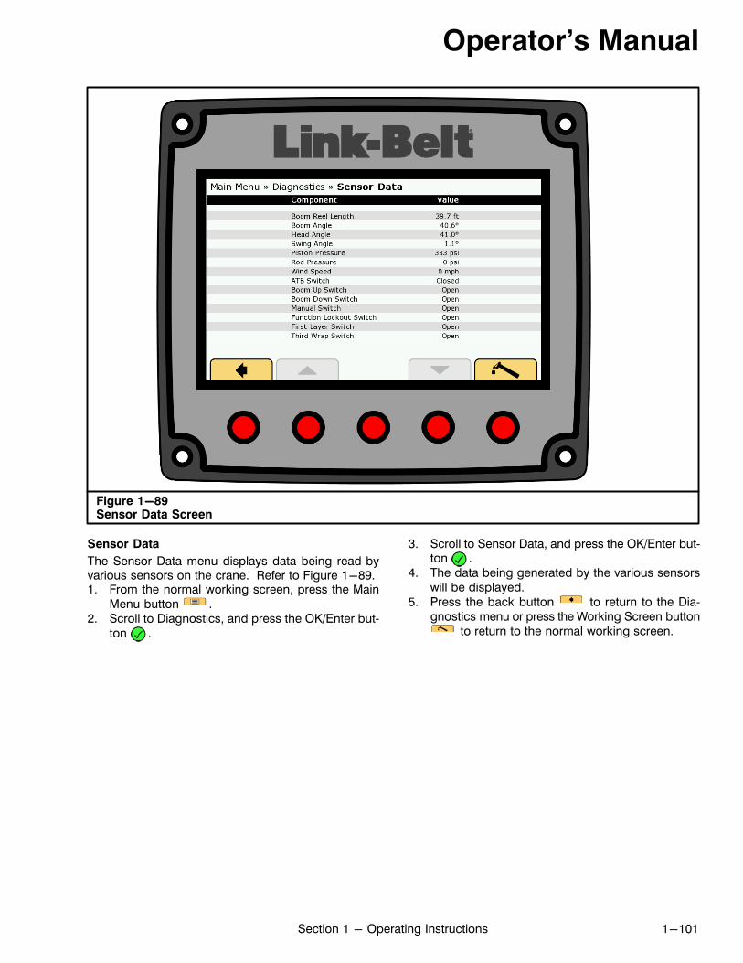
Operator's Manual
1-101Section 1 - Operating Instructions
Figure 1-89Sensor Data Screen
Sensor Data
The Sensor Data menu displays data being read byvarious sensors on the crane. Refer to Figure 1-89.1. From the normal working screen, press the Main
Menu button .2. Scroll to Diagnostics, and press the OK/Enter but
ton .
3. Scroll to Sensor Data, and press the OK/Enter button .
4. The data being generated by the various sensorswill be displayed.
5. Press the back button to return to the Diagnostics menu or press the Working Screen button
to return to the normal working screen.
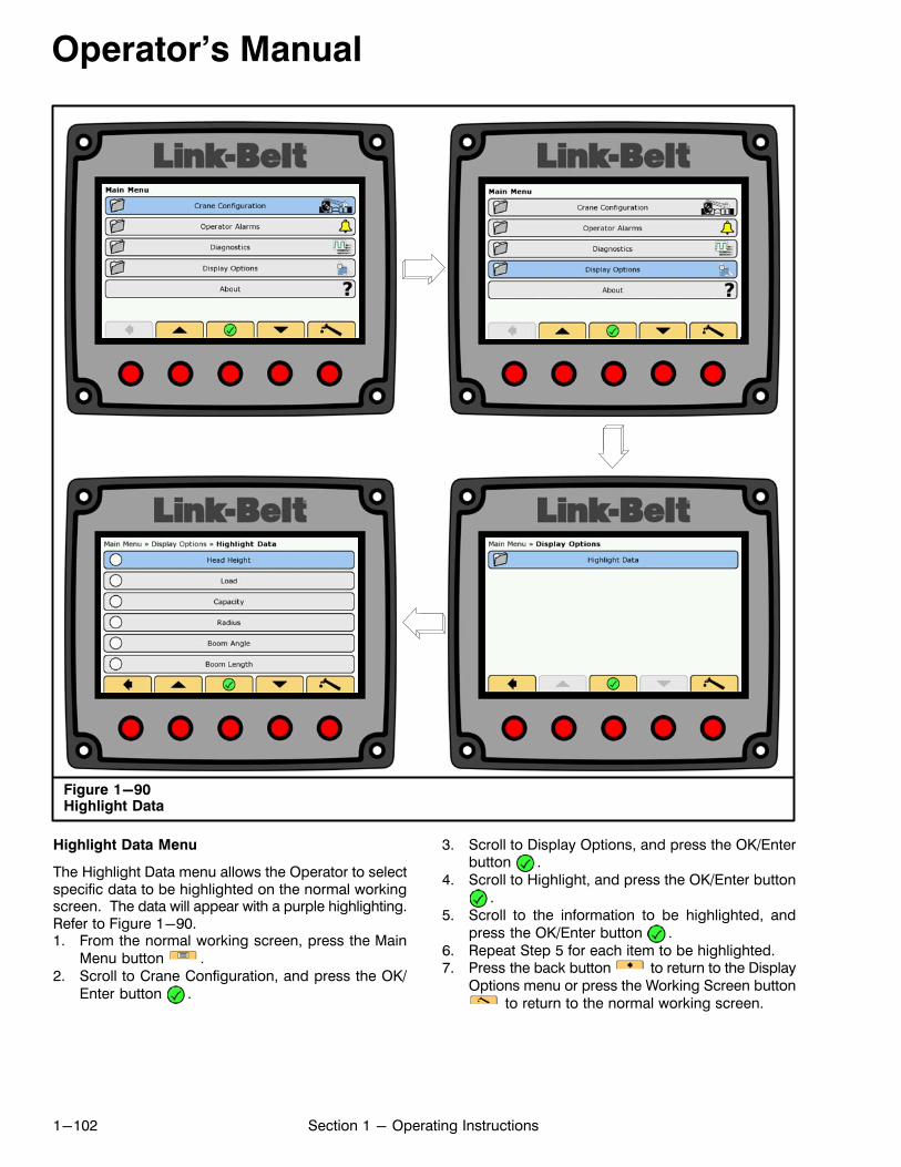
Operator's Manual
1-102 Section 1 - Operating Instructions
Figure 1-90Highlight Data
Highlight Data Menu
The Highlight Data menu allows the Operator to selectspecific data to be highlighted on the normal workingscreen. The data will appear with a purple highlighting.Refer to Figure 1-90.1. From the normal working screen, press the Main
Menu button .2. Scroll to Crane Configuration, and press the OK/
Enter button .
3. Scroll to Display Options, and press the OK/Enterbutton .
4. Scroll to Highlight, and press the OK/Enter button.
5. Scroll to the information to be highlighted, andpress the OK/Enter button .
6. Repeat Step 5 for each item to be highlighted.7. Press the back button to return to the Display
Options menu or press the Working Screen button to return to the normal working screen.
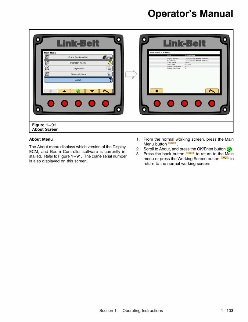
Operator's Manual
1-103Section 1 - Operating Instructions
Figure 1-91About Screen
About Menu
The About menu displays which version of the Display,ECM, and Boom Controller software is currently installed. Refer to Figure 1-91. The crane serial numberis also displayed on this screen.
1. From the normal working screen, press the MainMenu button .
2. Scroll to About, and press the OK/Enter button .3. Press the back button to return to the Main
menu or press the Working Screen button toreturn to the normal working screen.
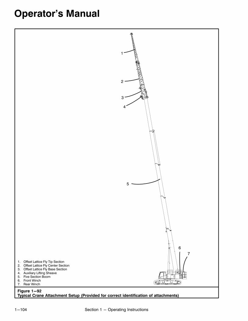
Operator's Manual
1-104 Section 1 - Operating Instructions
Figure 1-92Typical Crane Attachment Setup (Provided for correct identification of attachments)
1. Offset Lattice Fly Tip Section2. Offset Lattice Fly Center Section3. Offset Lattice Fly Base Section4. Auxiliary Lifting Sheave5. Five Section Boom6. Front Winch7. Rear Winch
1
2
3
4
5
6
7
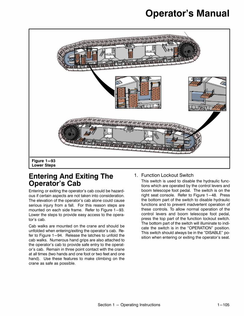
Operator's Manual
1-105Section 1 - Operating Instructions
Figure 1-93Lower Steps
Entering And Exiting TheOperator's CabEntering or exiting the operator's cab could be hazardous if certain aspects are not taken into consideration.The elevation of the operator's cab alone could causeserious injury from a fall. For this reason steps aremounted on each side frame. Refer to Figure 1-93.Lower the steps to provide easy access to the operator's cab.
Cab walks are mounted on the crane and should beunfolded when entering/exiting the operator's cab. Refer to Figure 1-94. Release the latches to unfold thecab walks. Numerous hand grips are also attached tothe operator's cab to provide safe entry to the operator's cab. Remain in three point contact with the craneat all times (two hands and one foot or two feet and onehand). Use these features to make climbing on thecrane as safe as possible.
1. Function Lockout SwitchThis switch is used to disable the hydraulic functions which are operated by the control levers andboom telescope foot pedal. The switch is on theright seat console. Refer to Figure 1-48. Pressthe bottom part of the switch to disable hydraulicfunctions and to prevent inadvertent operation ofthese controls. To allow normal operation of thecontrol levers and boom telescope foot pedal,press the top part of the function lockout switch.The bottom part of the switch will illuminate to indicate the switch is in the “OPERATION” position.This switch should always be in the “DISABLE” position when entering or exiting the operator's seat.
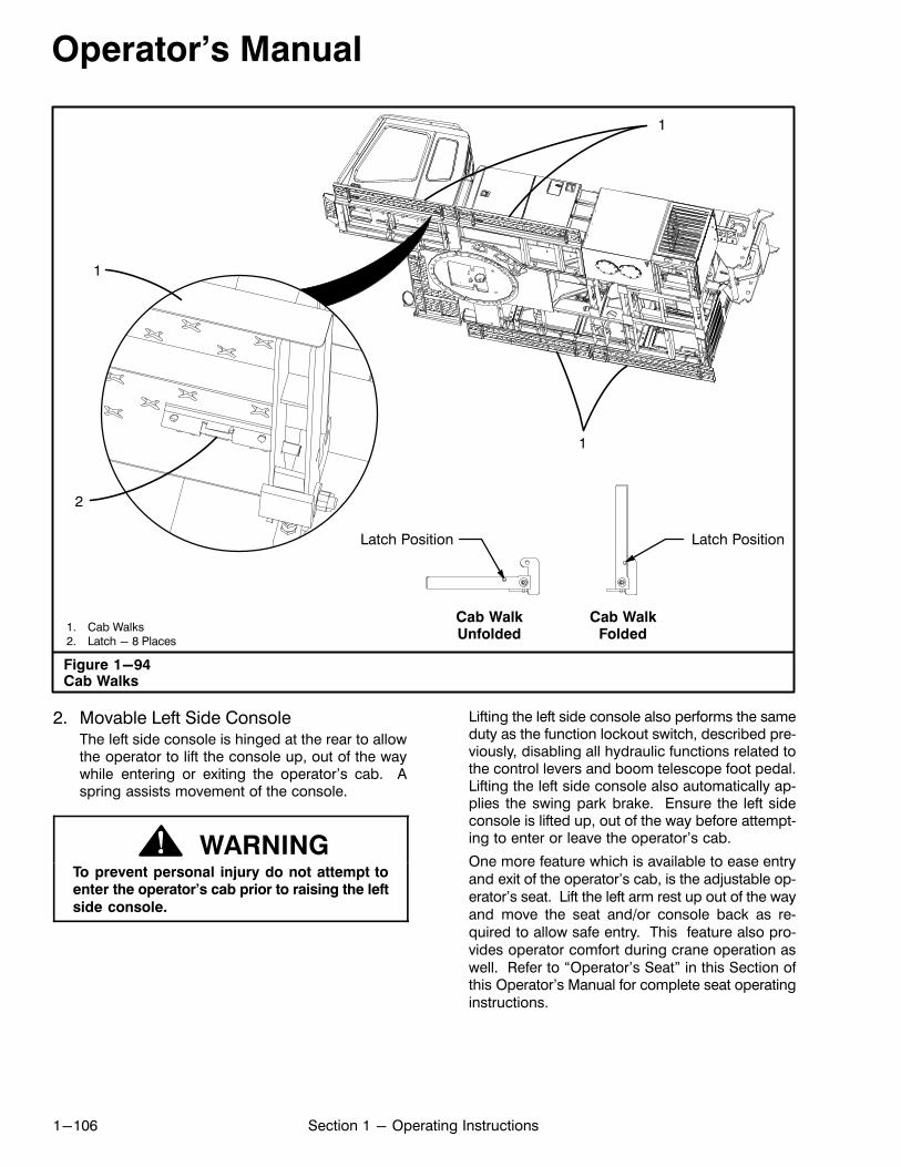
Operator's Manual
1-106 Section 1 - Operating Instructions
1. Cab Walks2. Latch - 8 Places
Figure 1-94Cab Walks
1
2
1
1
Cab WalkFolded
Cab WalkUnfolded
Latch Position Latch Position
2. Movable Left Side ConsoleThe left side console is hinged at the rear to allowthe operator to lift the console up, out of the waywhile entering or exiting the operator's cab. Aspring assists movement of the console.
WARNINGTo prevent personal injury do not attempt toenter the operator's cab prior to raising the left
side console.
Lifting the left side console also performs the sameduty as the function lockout switch, described previously, disabling all hydraulic functions related tothe control levers and boom telescope foot pedal.Lifting the left side console also automatically applies the swing park brake. Ensure the left sideconsole is lifted up, out of the way before attempting to enter or leave the operator's cab.
One more feature which is available to ease entryand exit of the operator's cab, is the adjustable operator's seat. Lift the left arm rest up out of the wayand move the seat and/or console back as required to allow safe entry. This feature also provides operator comfort during crane operation aswell. Refer to “Operator's Seat” in this Section ofthis Operator's Manual for complete seat operatinginstructions.
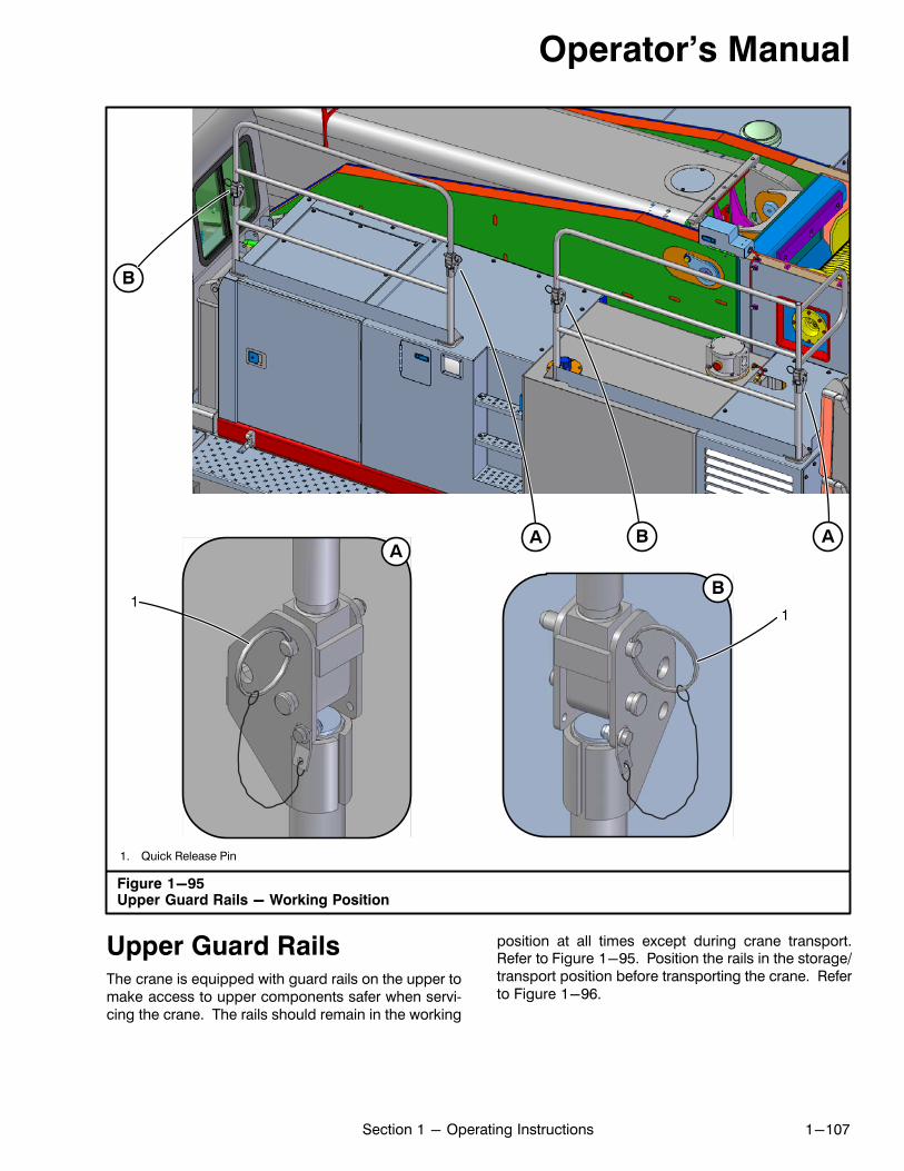
Operator's Manual
1-107Section 1 - Operating Instructions
1. Quick Release Pin
Figure 1-95Upper Guard Rails - Working Position
B
B A
B1
AA
1
Upper Guard RailsThe crane is equipped with guard rails on the upper tomake access to upper components safer when servicing the crane. The rails should remain in the working
position at all times except during crane transport.Refer to Figure 1-95. Position the rails in the storage/transport position before transporting the crane. Referto Figure 1-96.
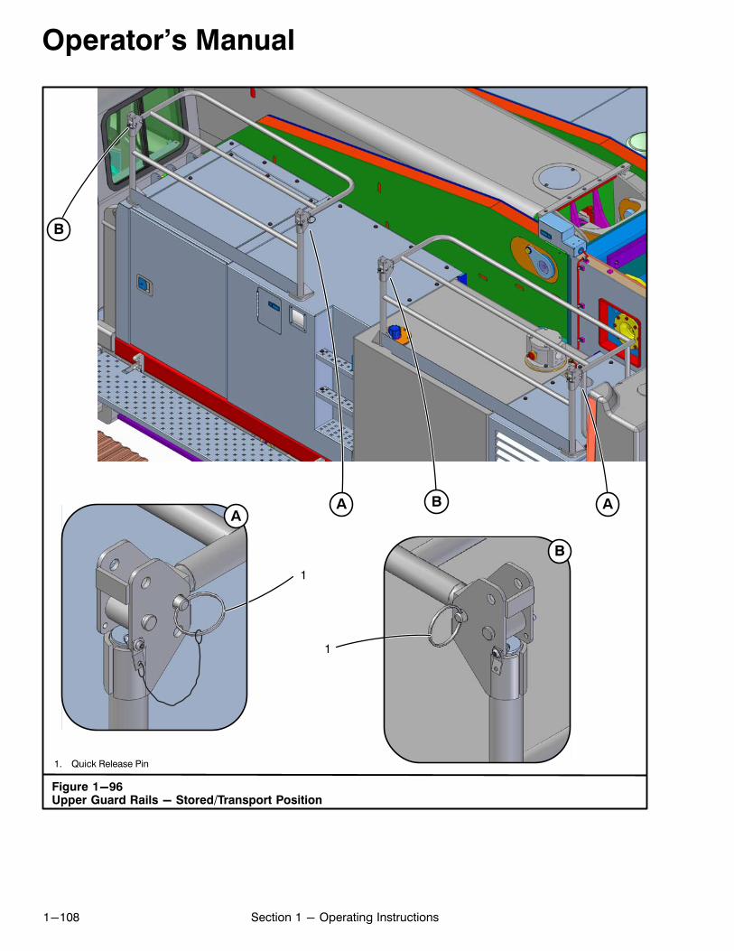
Operator's Manual
1-108 Section 1 - Operating Instructions
1. Quick Release Pin
Figure 1-96Upper Guard Rails - Stored/Transport Position
1
B
ABA A
B
1
Operator's Manual
1-109Section 1 - Operating Instructions
Before Starting OperationsBefore starting daily operations, make the followingchecks and inspections:
EngineCheck fuel, oil, and cooling systems for proper fluid levels. Check for leaks. Repair or fill as required. Refer tothe engine manufacturer's manual for additional information.
Gear CasesVisually inspect all gear cases for leaks or damage. Ifleaks or damage exists, repair and fill case(s) to properlubrication level.
Hydraulic SystemCheck all hoses for chafing, bulging, or other damage.Replace as necessary. Inspect hydraulic system for external leaks. Repair as needed. Check hydraulic reservoir oil level. Add oil if necessary.
LubricationLubricate the crane as outlined in Section 2 of this Operator's Manual.
Note: Operators may have nothing to do with lubri
cation or maintenance of the crane, but it could beadvantageous for them to be familiar with it. Knowl
edge of preventive maintenance makes the opera
tor more aware of malfunctions in the crane so re
pairs can be made with a minimum of downtime.
Wire Rope And SheavesInspect all wire rope and sheaves for damage or deterioration. Replace as necessary.
General InspectionVisually inspect the entire crane for loose or missingcotter pins, bolts, boom damage, or fly chord and/orlattice damage. Check for oil or fluid leaks. Make repairs as needed.
Electrical SystemCheck the operation of all lights, windshield wipers,horns, etc. Repair as needed.
ControlsCheck all controls for proper operation and adjustment. Repair as needed.
Fire ExtinguisherA fire extinguisher is mounted in the operator's cab. Itis an ABC type fire extinguisher, meaning it is capableof extinguishing most types of fires. The operatorshould be familiar with its location, the clampmechanism used to secure it in place, and foremost theoperation of the device. Specific instructions,regarding operation, are given on the label attached on
the fire extinguisher. A charge indicator on the fireextinguisher monitors the pressure within the tank.Check the indicator daily to ensure the fire extinguisheris adequately charged and ready for use.
Boom Distortion Due To Thermal EffectsOf The SunThe heat from the sun may have a thermal effect on thesides of telescopic booms causing the sides of theboom to expand (lengthen). The sides of the boommay not expand equally if the boom is extended forlong periods of time with only one side of the boom exposed to the sun. The unequal expansion may causeboom distortion (the boom may “deflect” to one side).This is more noticeable with long boom lengths and/orlong booms with long lattice flys attached to the boom.
For example, a 100 ft (30.5m) main boom, with a 50°F(10°C ) temperature differential between the two sidesof the boom, may cause the centerline of the mainboom head to “deflect” as much as 3 ft (0.9m) off thecenterline of the crane. Attaching a lattice fly to thesame boom may cause the centerline of the fly head to“deflect” even more off the centerline of the crane. This“deflection” to one side creates a “side load” on theboom and/or fly. Side load on a boom or fly, whetherinduced by the load or thermal effects, is dangerousand shall be avoided.
Prior to lifting any loads, inspect the boom or boom andfly combination to ensure they are straight. If the boomor boom and fly combination is not straight, ensure thatall the boom wear pads are properly adjusted.
If the boom is distorted due to temperature differentialon the sides of the boom, reposition the boom to allowthe thermal effects from the sun to equalize the temperatures of the side walls of the boom to eliminate the distortion before lifting a load.
Engine Starting Procedure
WARNINGThis Operator's Manual and the enginemanufacturer's manual must be thoroughly
read and understood by the operator before
starting the engine. Major crane damage
and/or serious personal injury could result
from improper operating procedures.
Before attempting to start the engine, the operator shouldcarefully read and understand the engine startinginstructions in the engine manufacturer's manual andthis Operator's Manual. Attempting to start or run theengine before studying these instructions may result inengine damage. With the crane fully serviced and theoperator familiar with all gauges, switches, controls, andhaving read and fully understood this entire Operator'sManual, start the engine using the following procedures.
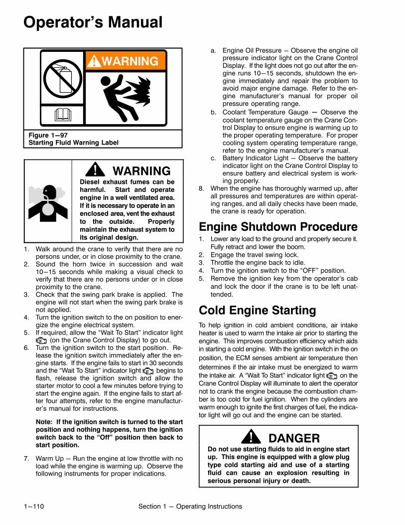
Operator's Manual
1-110 Section 1 - Operating Instructions
Figure 1-97Starting Fluid Warning Label
WARNING
WARNINGDiesel exhaust fumes can beharmful. Start and operate
engine in a well ventilated area.
If it is necessary to operate in an
enclosed area, vent the exhaust
to the outside. Properly
maintain the exhaust system to
its original design.
1. Walk around the crane to verify that there are nopersons under, or in close proximity to the crane.
2. Sound the horn twice in succession and wait10-15 seconds while making a visual check toverify that there are no persons under or in closeproximity to the crane.
3. Check that the swing park brake is applied. Theengine will not start when the swing park brake isnot applied.
4. Turn the ignition switch to the on position to energize the engine electrical system.
5. If required, allow the “Wait To Start” indicator light (on the Crane Control Display) to go out.
6. Turn the ignition switch to the start position. Release the ignition switch immediately after the engine starts. If the engine fails to start in 30 secondsand the “Wait To Start” indicator light begins toflash, release the ignition switch and allow thestarter motor to cool a few minutes before trying tostart the engine again. If the engine fails to start after four attempts, refer to the engine manufacturer's manual for instructions.
Note: If the ignition switch is turned to the startposition and nothing happens, turn the ignitionswitch back to the “Off” position then back tostart position.
7. Warm Up - Run the engine at low throttle with noload while the engine is warming up. Observe thefollowing instruments for proper indications.
a. Engine Oil Pressure - Observe the engine oilpressure indicator light on the Crane ControlDisplay. If the light does not go out after the engine runs 10-15 seconds, shutdown the engine immediately and repair the problem toavoid major engine damage. Refer to the engine manufacturer's manual for proper oilpressure operating range.
b. Coolant Temperature Gauge - Observe thecoolant temperature gauge on the Crane Control Display to ensure engine is warming up tothe proper operating temperature. For propercooling system operating temperature range,refer to the engine manufacturer's manual.
c. Battery Indicator Light - Observe the batteryindicator light on the Crane Control Display toensure battery and electrical system is working properly.
8. When the engine has thoroughly warmed up, afterall pressures and temperatures are within operating ranges, and all daily checks have been made,the crane is ready for operation.
Engine Shutdown Procedure1. Lower any load to the ground and properly secure it.
Fully retract and lower the boom.2. Engage the travel swing lock.3. Throttle the engine back to idle.4. Turn the ignition switch to the “OFF” position.5. Remove the ignition key from the operator's cab
and lock the door if the crane is to be left unattended.
Cold Engine StartingTo help ignition in cold ambient conditions, air intakeheater is used to warm the intake air prior to starting theengine. This improves combustion efficiency which aidsin starting a cold engine. With the ignition switch in the on
position, the ECM senses ambient air temperature then
determines if the air intake must be energized to warm
the intake air. A “Wait To Start” indicator light on theCrane Control Display will illuminate to alert the operatornot to crank the engine because the combustion chamber is too cold for fuel ignition. When the cylinders arewarm enough to ignite the first charges of fuel, the indicator light will go out and the engine can be started.
DANGERDo not use starting fluids to aid in engine startup. This engine is equipped with a glow plug
type cold starting aid and use of a starting
fluid can cause an explosion resulting in
serious personal injury or death.
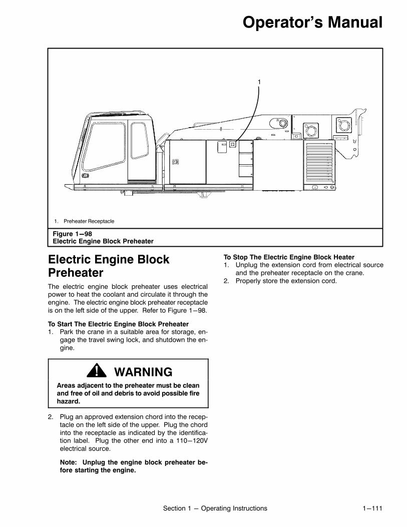
Operator's Manual
1-111Section 1 - Operating Instructions
Figure 1-98Electric Engine Block Preheater
1. Preheater Receptacle
1
Electric Engine BlockPreheaterThe electric engine block preheater uses electricalpower to heat the coolant and circulate it through theengine. The electric engine block preheater receptacleis on the left side of the upper. Refer to Figure 1-98.
To Start The Electric Engine Block Preheater1. Park the crane in a suitable area for storage, en
gage the travel swing lock, and shutdown the engine.
WARNINGAreas adjacent to the preheater must be cleanand free of oil and debris to avoid possible fire
hazard.
2. Plug an approved extension chord into the receptacle on the left side of the upper. Plug the chordinto the receptacle as indicated by the identification label. Plug the other end into a 110-120Velectrical source.
Note: Unplug the engine block preheater before starting the engine.
To Stop The Electric Engine Block Heater1. Unplug the extension cord from electrical source
and the preheater receptacle on the crane.2. Properly store the extension cord.
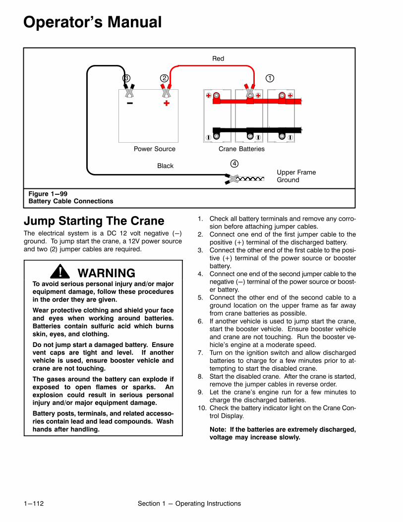
Operator's Manual
1-112 Section 1 - Operating Instructions
Figure 1-99Battery Cable Connections
Power Source
23
4
1
Upper FrameGround
Crane Batteries
Red
Black
ÌÌÌÌ
Jump Starting The CraneThe electrical system is a DC 12 volt negative (-)ground. To jump start the crane, a 12V power sourceand two (2) jumper cables are required.
WARNINGTo avoid serious personal injury and/or majorequipment damage, follow these procedures
in the order they are given.
Wear protective clothing and shield your face
and eyes when working around batteries.
Batteries contain sulfuric acid which burns
skin, eyes, and clothing.
Do not jump start a damaged battery. Ensurevent caps are tight and level. If another
vehicle is used, ensure booster vehicle and
crane are not touching.
The gases around the battery can explode if
exposed to open flames or sparks. An
explosion could result in serious personalinjury and/or major equipment damage.
Battery posts, terminals, and related accesso
ries contain lead and lead compounds. Wash
hands after handling.
1. Check all battery terminals and remove any corrosion before attaching jumper cables.
2. Connect one end of the first jumper cable to thepositive (+) terminal of the discharged battery.
3. Connect the other end of the first cable to the positive (+) terminal of the power source or boosterbattery.
4. Connect one end of the second jumper cable to thenegative (-) terminal of the power source or booster battery.
5. Connect the other end of the second cable to aground location on the upper frame as far awayfrom crane batteries as possible.
6. If another vehicle is used to jump start the crane,start the booster vehicle. Ensure booster vehicleand crane are not touching. Run the booster vehicle's engine at a moderate speed.
7. Turn on the ignition switch and allow dischargedbatteries to charge for a few minutes prior to attempting to start the disabled crane.
8. Start the disabled crane. After the crane is started,remove the jumper cables in reverse order.
9. Let the crane's engine run for a few minutes tocharge the discharged batteries.
10. Check the battery indicator light on the Crane Control Display.
Note: If the batteries are extremely discharged,voltage may increase slowly.
Operator's Manual
1-113Section 1 - Operating Instructions
General OperationThe following procedure contains helpful informationfor typical lift crane operation. This information is general in nature and is not intended to serve as a fail safeprocedure for any and all situations. The operatormust, at all times, be alert and fully aware of the loadrequirements and specific job site conditions. The operator must be ready and able to perform any changein procedure, in a moments notice, to safely operatethe crane as the immediate situation changes.
Note: Before operating the crane near airports, ra
dio and microwave towers, power lines, etc., always
review and comply with all local, state, and federallaws.
Lift Crane OperationCranes are used primarily for making heavy lifts. In order to do this properly, certain procedures must be followed. The following is a suggested procedure formaking typical lifts:1. Determine the weight to be lifted. Add the weight of
the hook block, hook ball, slings, rigging, fly, etc. Determine height to which the load must be lifted.
2. Refer to the Working Areas, Working Range, andthe appropriate capacity chart in the Crane RatingManual. Find the shortest boom length and loadradius that will accomplish the job and assemblethe crane accordingly.
3. Position the crane so a minimum swing is necessary.4. The crane must be supported by a firm, level sur
face before starting to lift. All capacities (except listcapacities) in the Crane Rating Manual are basedon the crane being level in all directions. If thecrane is not level, out swing or side swing of theload will greatly reduce lifting capacities and couldcause crane damage or an accident. If the groundis soft, use mats.
5. Check that the proper counterweight arrangementis properly installed. Do not make lifts which exceed capacity chart specifications.
6. Check that the correct configuration has been entered in the Rated Capacity Limiter (RCL).
7. Raise the boom and swing over the load.8. Lower the hook block or hook ball and fasten it to
the load. The following points must be observed:a. The boom head must be directly above the
load. (Booms are made to lift, and should notbe used to drag a load sideways.)
b. Always use chains, wire ropes, and/or slings ofample size and make periodic checks of theircondition.
c. Always use sufficient parts of line. Refer to theWire Rope Capacity Chart in the Crane RatingManual for the number of parts of line neededfor a given lift.
d. When lifting loads, care should be taken to prevent sudden loading or unloading of the winchwire rope. Ease into the load. Lift the load afew inches (centimeters) off the ground andhold to check the winch brakes.
9. Boom to the desired angle. Lift the load to the desired height. Be careful when booming down orswinging the load, as these increase the load radius and result in a decrease in capacity. Ensurethe load being lifted remains within the lifting capacity of the crane for the boom length, radius, andworking area being used.
10. Control the load at all times. Use hand lines toguide the load. Do not guide loads into place withyour hands. Swing slowly and smoothly. Avoidjerks when starting or stopping swings.
During OperationThe operator must remain alert to possible malfunctioning of the crane while operating. If the crane doesmalfunction, lower the load and shutdown the craneuntil the problem is found and corrected. During operation, the operator must:1. Remain alert to any noise, loss of power, or bad re
sponse to control of the crane. Watch the engineoil pressure indicator light and coolant temperature gauges for proper operating ranges.
2. Watch the hydraulic system oil temperaturegauge. If the temperature exceeds maximum temperature, shutdown the crane until the problem iscorrected. (Refer to Section 2 of this Operator'sManual for the maximum temperature for each viscosity of hydraulic oil.)
3. Listen for any unusual noises in the hydraulic system,power train, and gear boxes. If any, correct problem.
4. Watch for oil leaks or any loss of control. If any develop, correct before continuing operation.
5. Ensure all controls work freely and easily, with nosticking or binding. Lubricate or adjust as necessary.
6. Periodically check to confirm the crane is level andstable.
7. Heed all DANGER, WARNING, and CAUTION labels. Observe good safety practices at all times.
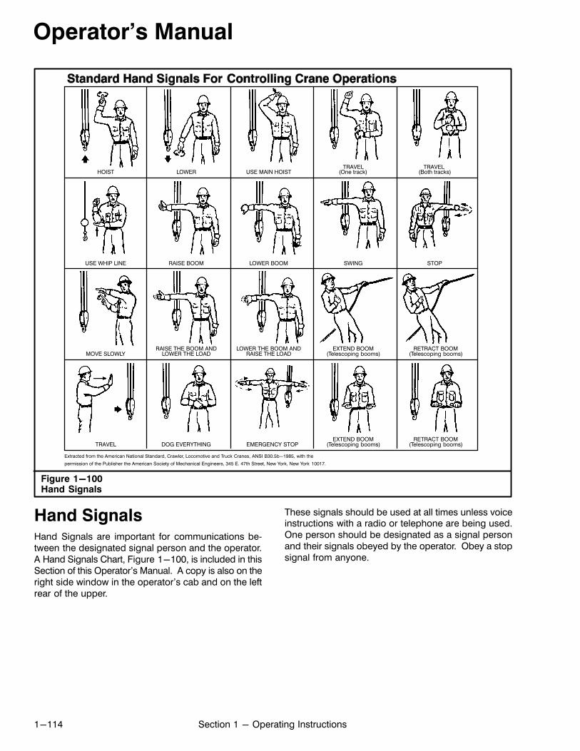
Operator's Manual
1-114 Section 1 - Operating Instructions
Figure 1-100Hand Signals
permission of the Publisher the American Society of Mechanical Engineers, 345 E. 47th Street, New York, New York 10017.
USE WHIP LINE
MOVE SLOWLY
TRAVEL
RAISE BOOM
LOWER THE LOAD
DOG EVERYTHING
LOWER
LOWER BOOM
RAISE THE LOAD
EMERGENCY STOP
USE MAIN HOIST
SWING
(Telescoping booms)
(One track)
STOP
(Both tracks)TRAVEL TRAVEL
EXTEND BOOM
(Telescoping booms)EXTEND BOOM
(Telescoping booms)RETRACT BOOM
(Telescoping booms)RETRACT BOOMRAISE THE BOOM AND LOWER THE BOOM AND
HOIST
Extracted from the American National Standard, Crawler, Locomotive and Truck Cranes, ANSI B30.5b-1985, with the
Hand SignalsHand Signals are important for communications between the designated signal person and the operator.A Hand Signals Chart, Figure 1-100, is included in thisSection of this Operator's Manual. A copy is also on theright side window in the operator's cab and on the leftrear of the upper.
These signals should be used at all times unless voiceinstructions with a radio or telephone are being used.One person should be designated as a signal personand their signals obeyed by the operator. Obey a stopsignal from anyone.
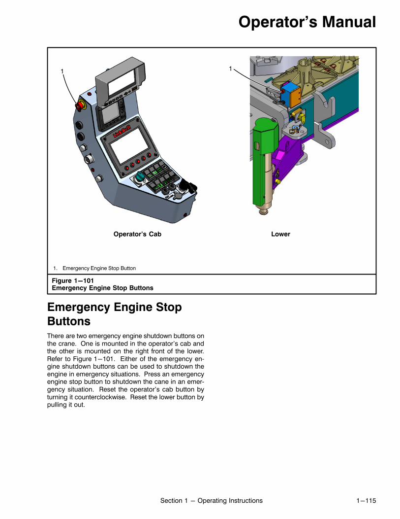
Operator's Manual
1-115Section 1 - Operating Instructions
Figure 1-101Emergency Engine Stop Buttons
1. Emergency Engine Stop Button
11
Operator's Cab Lower
Emergency Engine Stop
ButtonsThere are two emergency engine shutdown buttons onthe crane. One is mounted in the operator's cab andthe other is mounted on the right front of the lower.Refer to Figure 1-101. Either of the emergency engine shutdown buttons can be used to shutdown theengine in emergency situations. Press an emergencyengine stop button to shutdown the cane in an emergency situation. Reset the operator's cab button byturning it counterclockwise. Reset the lower button bypulling it out.
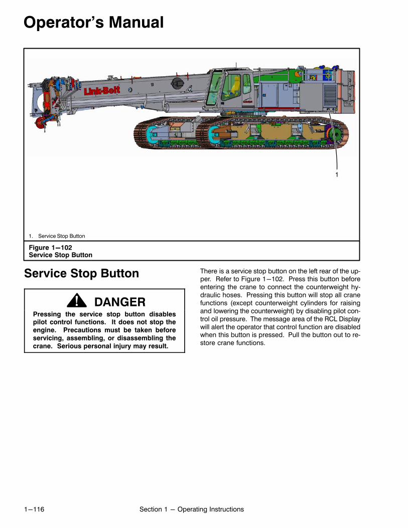
Operator's Manual
1-116 Section 1 - Operating Instructions
Figure 1-102Service Stop Button
1
1. Service Stop Button
Service Stop Button
DANGERPressing the service stop button disablespilot control functions. It does not stop the
engine. Precautions must be taken before
servicing, assembling, or disassembling the
crane. Serious personal injury may result.
There is a service stop button on the left rear of the upper. Refer to Figure 1-102. Press this button beforeentering the crane to connect the counterweight hydraulic hoses. Pressing this button will stop all cranefunctions (except counterweight cylinders for raisingand lowering the counterweight) by disabling pilot control oil pressure. The message area of the RCL Displaywill alert the operator that control function are disabledwhen this button is pressed. Pull the button out to restore crane functions.
Operator's Manual
1-117Section 1 - Operating Instructions
Crane Assembly And
DisassemblyWhen transporting, the crane may require disassembly.When at the job site, it will require reassembly. The following instructions are recommended, safe procedures for assembling and disassembling the crane.Due to job site conditions and the availability of auxiliaryequipment, other methods may be used only if they areproven, safe methods. If any questions exist about thesafety of any procedure, contact your Link‐Belt Distributor.
Crane Assembly
Note: When using the crane boom for lifting
during all self assembly procedures, use the
“Standard” boom mode and a fully retracted
boom.
1. Unload the crane from the transport vehicle. Referto “Unloading The Crane” in this Section of this Operator's Manual.
2. Install the lower counterweights if required. Referto “Lower Counterweight Installation“ in this Section of this Operator's Manual.
3. Install the side frames. Refer to “Side Frame Installation” in this Section of this Operator's Manual.
4. Install the upper counterweights. Refer to “UpperCounterweight Installation” in this Section of thisOperator's Manual.
Crane Disassembly
Note: When using the crane boom for lifting
during all self disassembly procedures, use the
“Standard” boom mode and a fully retracted
boom.
1. Extend the side frames to the fully extended position. Refer to “Extending The Side Frames” in thisSection of this Operator's Manual.
2. If equipped, store or remove the fly. Refer to Section 4 of this Operator's Manual.
3. Remove the upper counterweights. Refer to“Counterweight Installation And Removal” in thisSection of this Operator's Manual.
4. Remove the side frames. Refer to “Side Frame Removal” in this Section of this Operator's Manual.
5. Remove the lower counterweights. Refer to“Lower Counterweight Removal” in this Section ofthis Operator's Manual.
6. Load the crane onto the transport vehicle. Refer to“Loading The Crane” in this Section of this Operator's Manual.
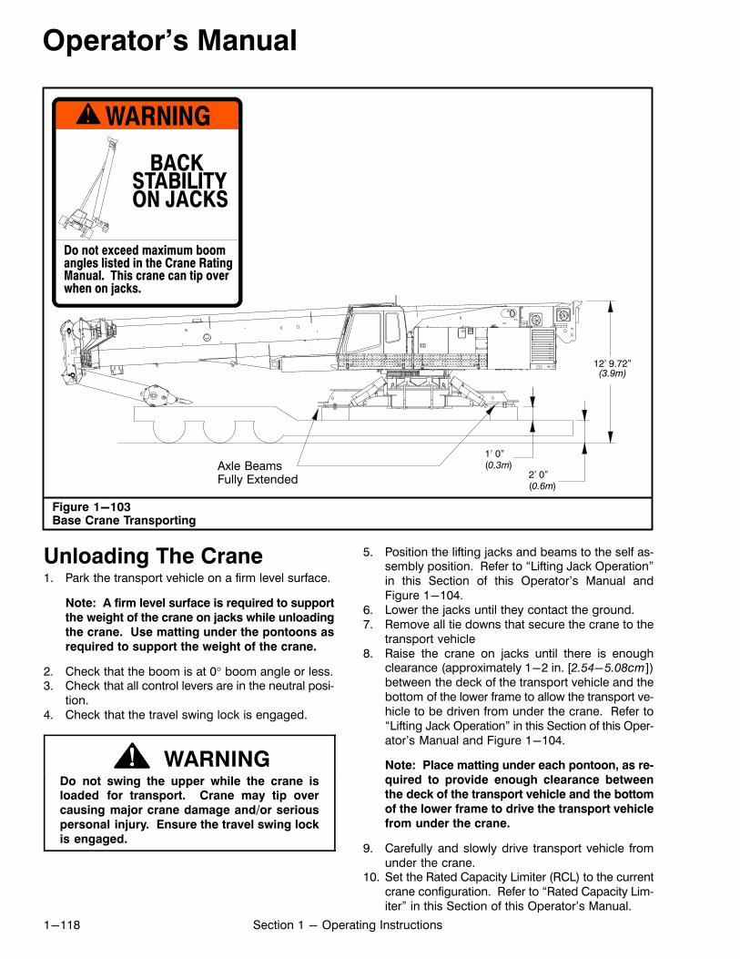
Operator's Manual
1-118 Section 1 - Operating Instructions
Figure 1-103Base Crane Transporting
12' 9.72”(3.9m)
1' 0”(0.3m)
Do not exceed maximum boomangles listed in the Crane RatingManual. This crane can tip overwhen on jacks.
WARNING
BACKSTABILITYON JACKS
2' 0”(0.6m)
Axle BeamsFully Extended
Unloading The Crane1. Park the transport vehicle on a firm level surface.
Note: A firm level surface is required to support
the weight of the crane on jacks while unloading
the crane. Use matting under the pontoons as
required to support the weight of the crane.
2. Check that the boom is at 0� boom angle or less.3. Check that all control levers are in the neutral posi
tion.4. Check that the travel swing lock is engaged.
WARNINGDo not swing the upper while the crane isloaded for transport. Crane may tip over
causing major crane damage and/or serious
personal injury. Ensure the travel swing lock
is engaged.
5. Position the lifting jacks and beams to the self assembly position. Refer to “Lifting Jack Operation”in this Section of this Operator's Manual andFigure 1-104.
6. Lower the jacks until they contact the ground.7. Remove all tie downs that secure the crane to the
transport vehicle8. Raise the crane on jacks until there is enough
clearance (approximately 1-2 in. [2.54-5.08cm])between the deck of the transport vehicle and thebottom of the lower frame to allow the transport vehicle to be driven from under the crane. Refer to“Lifting Jack Operation” in this Section of this Operator's Manual and Figure 1-104.
Note: Place matting under each pontoon, as re
quired to provide enough clearance between
the deck of the transport vehicle and the bottom
of the lower frame to drive the transport vehicle
from under the crane.
9. Carefully and slowly drive transport vehicle fromunder the crane.
10. Set the Rated Capacity Limiter (RCL) to the currentcrane configuration. Refer to “Rated Capacity Limiter” in this Section of this Operator's Manual.
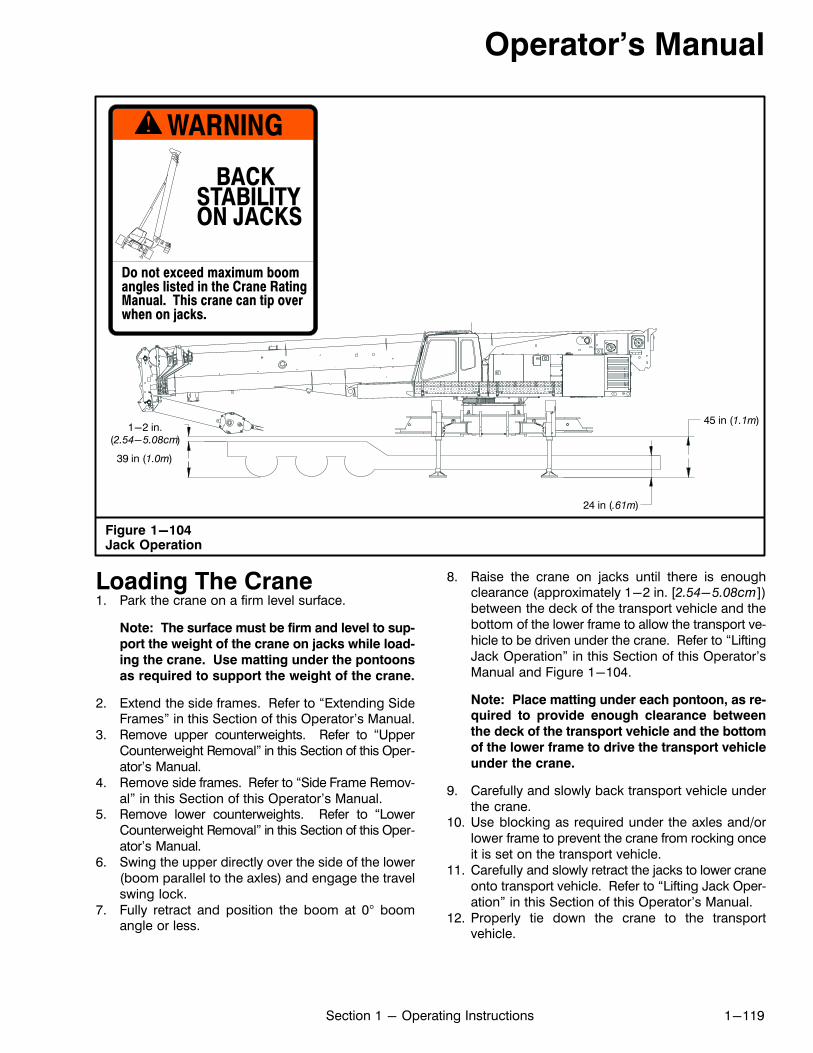
Operator's Manual
1-119Section 1 - Operating Instructions
Figure 1-104Jack Operation
39 in (1.0m)
45 in (1.1m)
24 in (.61m)
Do not exceed maximum boomangles listed in the Crane RatingManual. This crane can tip overwhen on jacks.
WARNING
BACKSTABILITYON JACKS
1-2 in.(2.54-5.08cm)
Loading The Crane1. Park the crane on a firm level surface.
Note: The surface must be firm and level to sup
port the weight of the crane on jacks while load
ing the crane. Use matting under the pontoons
as required to support the weight of the crane.
2. Extend the side frames. Refer to “Extending SideFrames” in this Section of this Operator's Manual.
3. Remove upper counterweights. Refer to “UpperCounterweight Removal” in this Section of this Operator's Manual.
4. Remove side frames. Refer to “Side Frame Removal” in this Section of this Operator's Manual.
5. Remove lower counterweights. Refer to “LowerCounterweight Removal” in this Section of this Operator's Manual.
6. Swing the upper directly over the side of the lower(boom parallel to the axles) and engage the travelswing lock.
7. Fully retract and position the boom at 0° boomangle or less.
8. Raise the crane on jacks until there is enoughclearance (approximately 1-2 in. [2.54-5.08cm])between the deck of the transport vehicle and thebottom of the lower frame to allow the transport vehicle to be driven under the crane. Refer to “LiftingJack Operation” in this Section of this Operator'sManual and Figure 1-104.
Note: Place matting under each pontoon, as required to provide enough clearance between
the deck of the transport vehicle and the bottom
of the lower frame to drive the transport vehicle
under the crane.
9. Carefully and slowly back transport vehicle underthe crane.
10. Use blocking as required under the axles and/orlower frame to prevent the crane from rocking onceit is set on the transport vehicle.
11. Carefully and slowly retract the jacks to lower craneonto transport vehicle. Refer to “Lifting Jack Operation” in this Section of this Operator's Manual.
12. Properly tie down the crane to the transportvehicle.
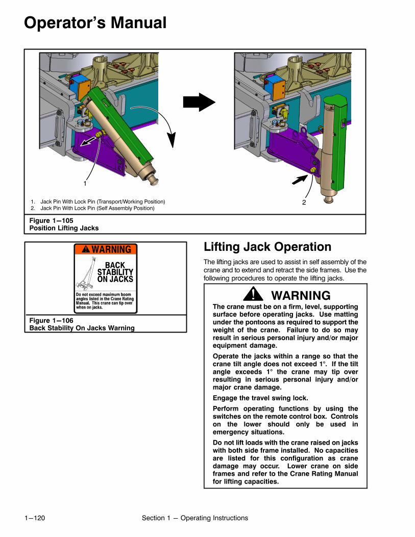
Operator's Manual
1-120 Section 1 - Operating Instructions
1. Jack Pin With Lock Pin (Transport/Working Position)2. Jack Pin With Lock Pin (Self Assembly Position)
Figure 1-105Position Lifting Jacks
1
2
Figure 1-106Back Stability On Jacks Warning
Lifting Jack OperationThe lifting jacks are used to assist in self assembly of thecrane and to extend and retract the side frames. Use thefollowing procedures to operate the lifting jacks.
WARNINGThe crane must be on a firm, level, supportingsurface before operating jacks. Use mattingunder the pontoons as required to support theweight of the crane. Failure to do so mayresult in serious personal injury and/or majorequipment damage.
Operate the jacks within a range so that thecrane tilt angle does not exceed 1°. If the tiltangle exceeds 1° the crane may tip overresulting in serious personal injury and/ormajor crane damage.
Engage the travel swing lock.
Perform operating functions by using theswitches on the remote control box. Controlson the lower should only be used inemergency situations.
Do not lift loads with the crane raised on jackswith both side frame installed. No capacitiesare listed for this configuration as cranedamage may occur. Lower crane on sideframes and refer to the Crane Rating Manualfor lifting capacities.
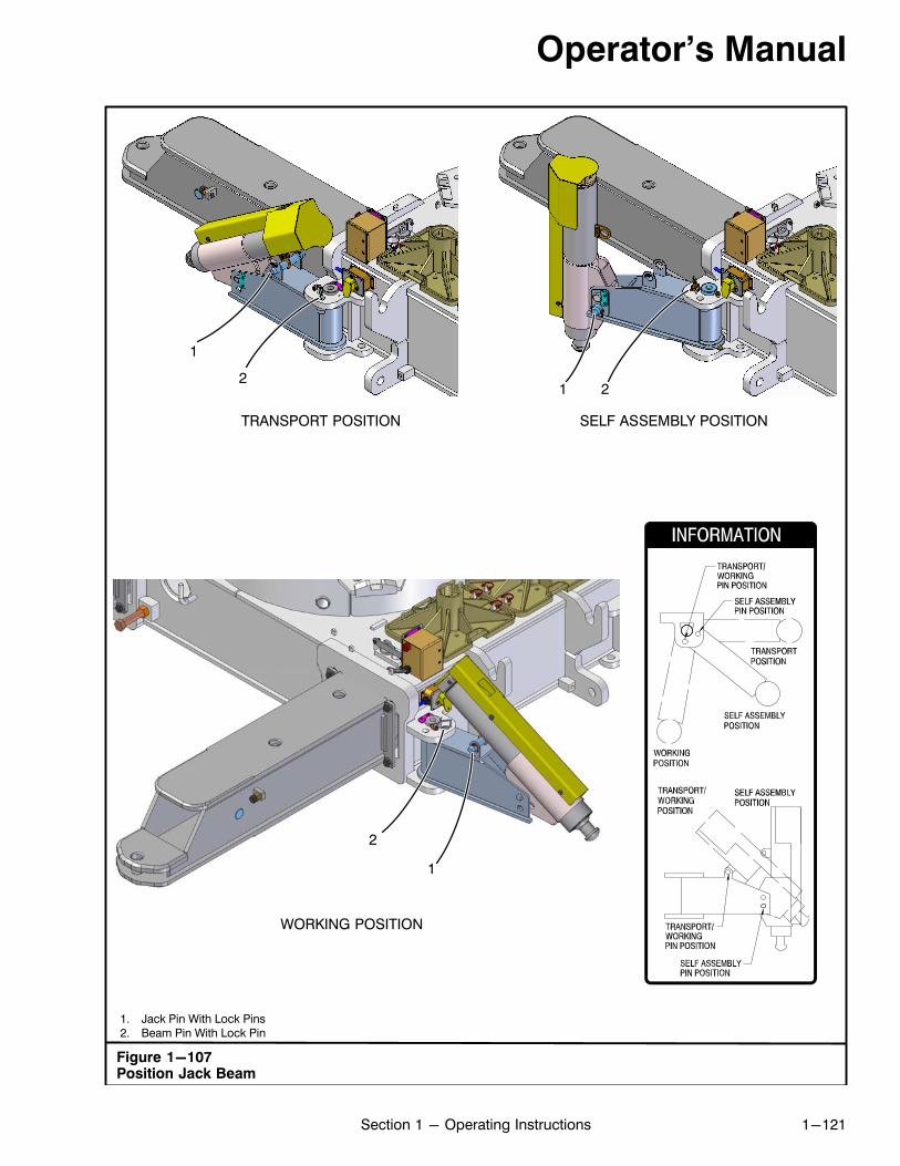
Operator's Manual
1-121Section 1 - Operating Instructions
1. Jack Pin With Lock Pins2. Beam Pin With Lock Pin
Figure 1-107Position Jack Beam
1
TRANSPORT POSITION SELF ASSEMBLY POSITION
12
2
WORKING POSITION
1
2
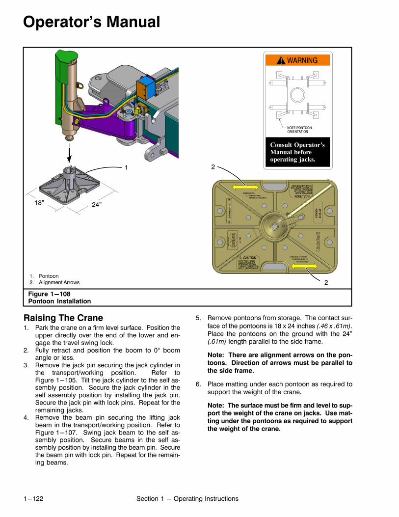
Operator's Manual
1-122 Section 1 - Operating Instructions
Figure 1-108Pontoon Installation
1. Pontoon2. Alignment Arrows
1
24”18”
2
2
Consult Operator’sManual beforeoperating jacks.
Raising The Crane1. Park the crane on a firm level surface. Position the
upper directly over the end of the lower and engage the travel swing lock.
2. Fully retract and position the boom to 0° boomangle or less.
3. Remove the jack pin securing the jack cylinder inthe transport/working position. Refer toFigure 1-105. Tilt the jack cylinder to the self assembly position. Secure the jack cylinder in theself assembly position by installing the jack pin.Secure the jack pin with lock pins. Repeat for theremaining jacks.
4. Remove the beam pin securing the lifting jackbeam in the transport/working position. Refer toFigure 1-107. Swing jack beam to the self assembly position. Secure beams in the self assembly position by installing the beam pin. Securethe beam pin with lock pin. Repeat for the remaining beams.
5. Remove pontoons from storage. The contact sur
face of the pontoons is 18 x 24 inches (.46 x .61m).Place the pontoons on the ground with the 24”(.61m) length parallel to the side frame.
Note: There are alignment arrows on the pon
toons. Direction of arrows must be parallel to
the side frame.
6. Place matting under each pontoon as required tosupport the weight of the crane.
Note: The surface must be firm and level to support the weight of the crane on jacks. Use mat
ting under the pontoons as required to support
the weight of the crane.
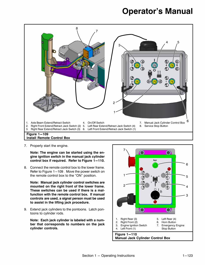
Operator's Manual
1-123Section 1 - Operating Instructions
1. Axle Beam Extend/Retract Switch2. Right Front Extend/Retract Jack Switch (2)3. Right Rear Extend/Retract Jack Switch (3)
4. On/Off Switch5. Left Rear Extend/Retract Jack Switch (4)6. Left Front Extend/Retract Jack Switch (1)
7. Manual Jack Cylinder Control Box8. Service Stop Button
Figure 1-109Install Remote Control Box
3
2
6
54
1
78
7. Properly start the engine.
Note: The engine can be started using the en
gine ignition switch in the manual jack cylinder
control box if required. Refer to Figure 1-110.
8. Connect the remote control box to the lower frame.Refer to Figure 1-109 . Move the power switch onthe remote control box to the “ON” position.
Note: Manual jack cylinder control switches aremounted on the right front of the lower frame.
These switches can be used if there is a mal
function with the remote control box. If manual
controls are used, a signal person must be used
to assist in the lifting jack procedure.
9. Extend jack cylinders to the pontoons. Latch pontoons to cylinder rods.
Note: Each jack cylinder is labeled with a num
ber that corresponds to numbers on the jack
cylinder controls.
Figure 1-110Manual Jack Cylinder Control Box
1. Right Rear (3)2. Right Front (2)3. Engine Ignition Switch4. Left Front (1)
5. Left Rear (4)6. Horn Button7. Emergency Engine
Stop Button
1
2 4
5
6
3
7
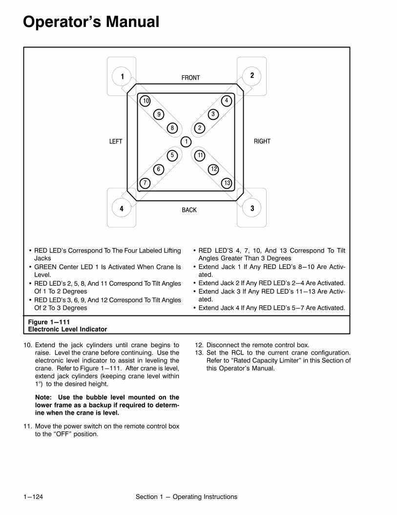
Operator's Manual
1-124 Section 1 - Operating Instructions
Figure 1-111Electronic Level Indicator
FRONT
BACK
LEFT RIGHT1
2
3
4
5
6
7
8
9
10
11
12
13
1 2
34
• RED LED's Correspond To The Four Labeled LiftingJacks
• GREEN Center LED 1 Is Activated When Crane IsLevel.
• RED LED's 2, 5, 8, And 11 Correspond To Tilt AnglesOf 1 To 2 Degrees
• RED LED's 3, 6, 9, And 12 Correspond To Tilt AnglesOf 2 To 3 Degrees
• RED LED'S 4, 7, 10, And 13 Correspond To TiltAngles Greater Than 3 Degrees
• Extend Jack 1 If Any RED LED's 8-10 Are Activated.
• Extend Jack 2 If Any RED LED's 2-4 Are Activated.
• Extend Jack 3 If Any RED LED's 11-13 Are Activated.
• Extend Jack 4 If Any RED LED's 5-7 Are Activated.
10. Extend the jack cylinders until crane begins toraise. Level the crane before continuing. Use theelectronic level indicator to assist in leveling thecrane. Refer to Figure 1-111. After crane is level,extend jack cylinders (keeping crane level within1°) to the desired height.
Note: Use the bubble level mounted on the
lower frame as a backup if required to determine when the crane is level.
11. Move the power switch on the remote control boxto the “OFF” position.
12. Disconnect the remote control box.13. Set the RCL to the current crane configuration.
Refer to “Rated Capacity Limiter” in this Section ofthis Operator's Manual.
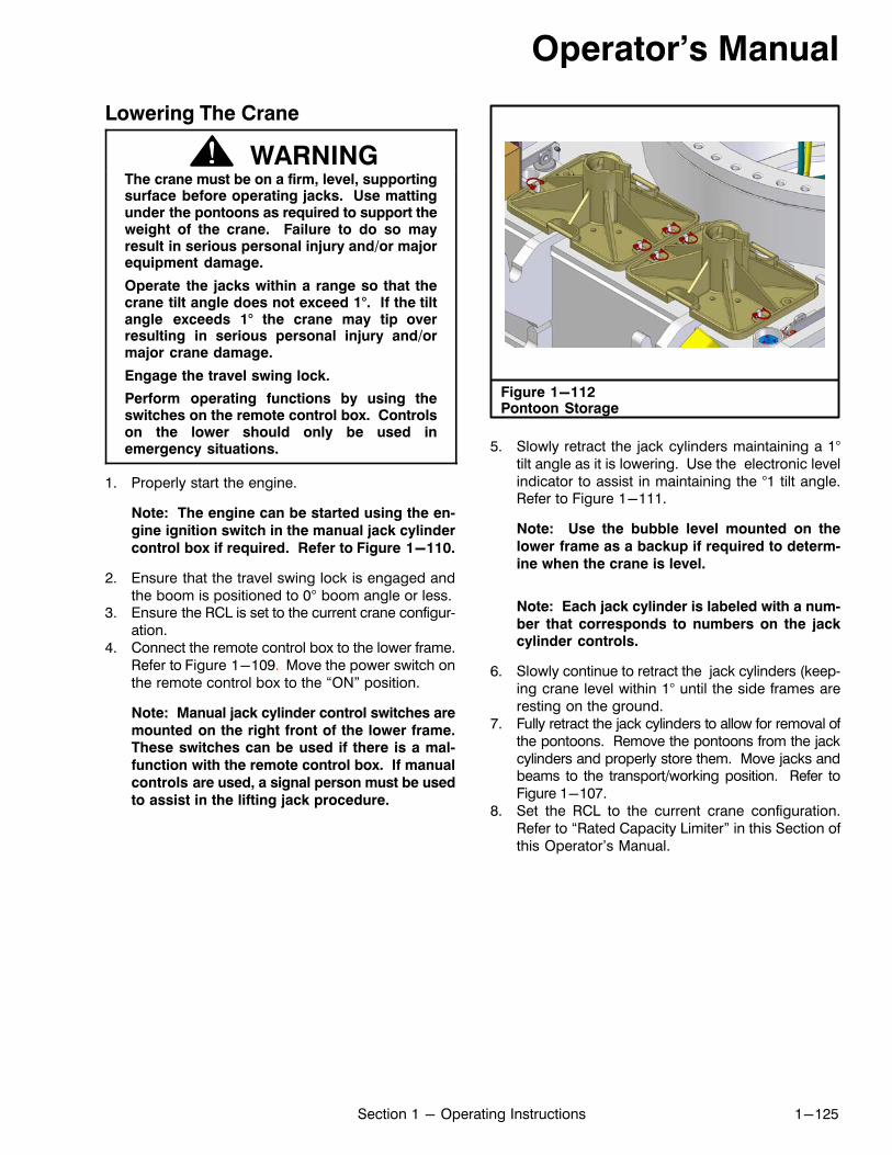
Operator's Manual
1-125Section 1 - Operating Instructions
Lowering The Crane
WARNINGThe crane must be on a firm, level, supportingsurface before operating jacks. Use mattingunder the pontoons as required to support theweight of the crane. Failure to do so mayresult in serious personal injury and/or majorequipment damage.
Operate the jacks within a range so that thecrane tilt angle does not exceed 1°. If the tiltangle exceeds 1° the crane may tip overresulting in serious personal injury and/ormajor crane damage.
Engage the travel swing lock.
Perform operating functions by using theswitches on the remote control box. Controlson the lower should only be used inemergency situations.
1. Properly start the engine.
Note: The engine can be started using the en
gine ignition switch in the manual jack cylinder
control box if required. Refer to Figure 1-110.
2. Ensure that the travel swing lock is engaged andthe boom is positioned to 0° boom angle or less.
3. Ensure the RCL is set to the current crane configuration.
4. Connect the remote control box to the lower frame.Refer to Figure 1-109. Move the power switch onthe remote control box to the “ON” position.
Note: Manual jack cylinder control switches are
mounted on the right front of the lower frame.These switches can be used if there is a mal
function with the remote control box. If manual
controls are used, a signal person must be used
to assist in the lifting jack procedure.
Figure 1-112Pontoon Storage
5. Slowly retract the jack cylinders maintaining a 1°tilt angle as it is lowering. Use the electronic levelindicator to assist in maintaining the °1 tilt angle.Refer to Figure 1-111.
Note: Use the bubble level mounted on the
lower frame as a backup if required to determ
ine when the crane is level.
Note: Each jack cylinder is labeled with a num
ber that corresponds to numbers on the jackcylinder controls.
6. Slowly continue to retract the jack cylinders (keeping crane level within 1° until the side frames areresting on the ground.
7. Fully retract the jack cylinders to allow for removal ofthe pontoons. Remove the pontoons from the jackcylinders and properly store them. Move jacks andbeams to the transport/working position. Refer toFigure 1-107.
8. Set the RCL to the current crane configuration.Refer to “Rated Capacity Limiter” in this Section ofthis Operator's Manual.
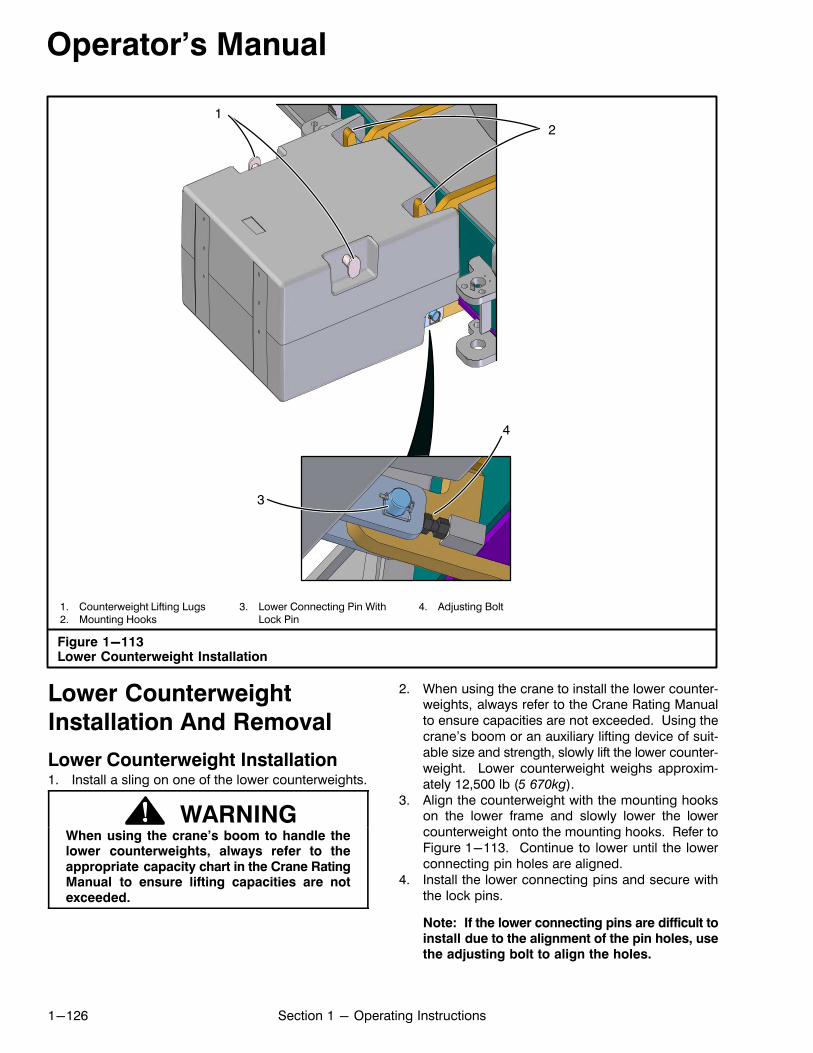
Operator's Manual
1-126 Section 1 - Operating Instructions
Figure 1-113Lower Counterweight Installation
1. Counterweight Lifting Lugs2. Mounting Hooks
3. Lower Connecting Pin WithLock Pin
4. Adjusting Bolt
12
3
4
Lower Counterweight
Installation And Removal
Lower Counterweight Installation1. Install a sling on one of the lower counterweights.
WARNINGWhen using the crane's boom to handle thelower counterweights, always refer to theappropriate capacity chart in the Crane RatingManual to ensure lifting capacities are notexceeded.
2. When using the crane to install the lower counterweights, always refer to the Crane Rating Manualto ensure capacities are not exceeded. Using thecrane's boom or an auxiliary lifting device of suitable size and strength, slowly lift the lower counterweight. Lower counterweight weighs approximately 12,500 lb (5 670kg).
3. Align the counterweight with the mounting hookson the lower frame and slowly lower the lowercounterweight onto the mounting hooks. Refer toFigure 1-113. Continue to lower until the lowerconnecting pin holes are aligned.
4. Install the lower connecting pins and secure withthe lock pins.
Note: If the lower connecting pins are difficult toinstall due to the alignment of the pin holes, usethe adjusting bolt to align the holes.
Operator's Manual
1-127Section 1 - Operating Instructions
5. Repeat Steps 1 through 4 for the other lower counterweight.
6. Set the RCL to the current crane configuration.Refer to “Rated Capacity Limiter” in this Section ofthis Operator's Manual.
Lower Counterweight Removal1. Remove the lower connecting pins. Refer to
Figure 1-113.2. Install a sling on one of the lower counterweights.
WARNINGWhen using the crane's boom to handle thelower counterweights, always refer to theappropriate capacity chart in the Crane RatingManual to ensure lifting capacities are notexceeded.
3. When using the crane to install the lower counterweights, always refer to the Crane Rating Manualto ensure capacities are not exceeded. Using thecrane's boom or an auxiliary lifting device of suitable size and strength, slowly lift the lower counterweight. Lower counterweight weighs approximately 12,500 lb (5 670kg).
4. Repeat Steps 1 through 3 for the other lower counterweight.
5. Set the RCL to the current crane configuration.Refer to “Rated Capacity Limiter” in this Section ofthis Operator's Manual.

Operator's Manual
1-128 Section 1 - Operating Instructions
Figure 1-114Side Frame Installation And Removal
1. Rated Capacity Radius 2. Lower Counterweight
12
12
Do not exceed maximum boomangles listed in the Crane RatingManual. This crane can tip overwhen on jacks.
WARNING
BACKSTABILITYON JACKS
Figure 1-115On Jacks, No Tracks Working Area
360° Side Frame Installation AndRemovalSide Frame Installation
WARNINGDo not place your body between the sideframe and lower frame during the installation
process. Serious personal injury may result.
1. Unload the crane from the transport vehicle. Refer to“Unloading The Crane” in this Section of this Operator's Manual.
2. Install lower counterweights if required. Refer to“Lower Counterweight Installation” in this Section ofthis Operator's Manual.
3. Remove axle beam covers. Refer to Figure 1-117.4. Ensure the RCL is set to the current crane configur
ation.
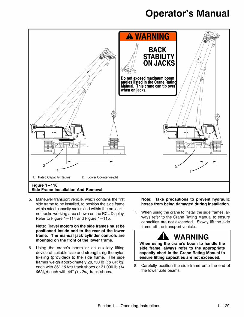
Operator's Manual
1-129Section 1 - Operating Instructions
1. Rated Capacity Radius 2. Lower Counterweight
Figure 1-116Side Frame Installation And Removal
12 2
1
Do not exceed maximum boomangles listed in the Crane RatingManual. This crane can tip overwhen on jacks.
WARNINGBACK
STABILITYON JACKS
5. Maneuver transport vehicle, which contains the firstside frame to be installed, to position the side framewithin rated capacity radius and within the on jacks,no tracks working area shown on the RCL Display.Refer to Figure 1-114 and Figure 1-115.
Note: Travel motors on the side frames must bepositioned inside and to the rear of the lowerframe. The manual jack cylinder controls aremounted on the front of the lower frame.
6. Using the crane's boom or an auxiliary liftingdevice of suitable size and strength, rig the nylontri‐sling (provided) to the side frame. The sideframes weigh approximately 28,750 lb (13 041kg)each with 36” (.91m) track shoes or 31,000 lb (14
062kg) each with 44” (1.12m) track shoes.
Note: Take precautions to prevent hydraulichoses from being damaged during installation.
7. When using the crane to install the side frames, always refer to the Crane Rating Manual to ensurecapacities are not exceeded. Slowly lift the sideframe off the transport vehicle.
WARNINGWhen using the crane's boom to handle theside frame, always refer to the appropriatecapacity chart in the Crane Rating Manual toensure lifting capacities are not exceeded.
8. Carefully position the side frame onto the end ofthe lower axle beams.

Operator's Manual
1-130 Section 1 - Operating Instructions
1. Retaining Pin And Cotter Pin2. 2.5” (6.35cm) Diameter Pin
3. 1” (2.54cm) Diameter Bolts4. Jam Nuts
5. Hydraulic Hoses6. Axle Beam Covers
Figure 1-117Side Frame Connection
1
3
4
5 6
3
4
2
Figure 1-118On Jacks, One Track Working Area
Over Side
9. Connect side frame to axle beams using the 2.5 in(6.35cm) diameter pins. Refer to Figure 1-117.Remove tri‐sling.
10. Position the boom at or below maximum angle listedat right. Slowly swing the upper over the side opposite the installed side frame.
WARNING
Track Counterweight Max Boom
Shoes Upper + Lower Angle
0+0 62°
0+A 72.5°
0+0 58°
0+A 68°
Do not exceed maximum boomangle before swinging the rear of
the upper over the same side as
the first installed side frame while
on jacks. Crane may turn over
backwards. Boom must be
positioned at or below themaximum angle listed below
before swinging the upper.
36”
44”

Operator's Manual
1-131Section 1 - Operating Instructions
1. Case Drain2. Side Frame Extend3. Side Frame Retract
4. Track Tension5. Two Speed Travel
6. Forward Travel7. Reverse Travel
Figure 1-119Hydraulic Hose Connections
43 5
2
A
6
7
A
B
B
1
11. Maneuver transport vehicle, which contains thesecond side frame to be installed, to the side opposite the installed side frame. Position the transportvehicle so the side frame is within the radius listed on
the following page and within on jacks, one trackworking area shown on the RCL Display. Refer toFigure 1-116 and Figure 1-118.
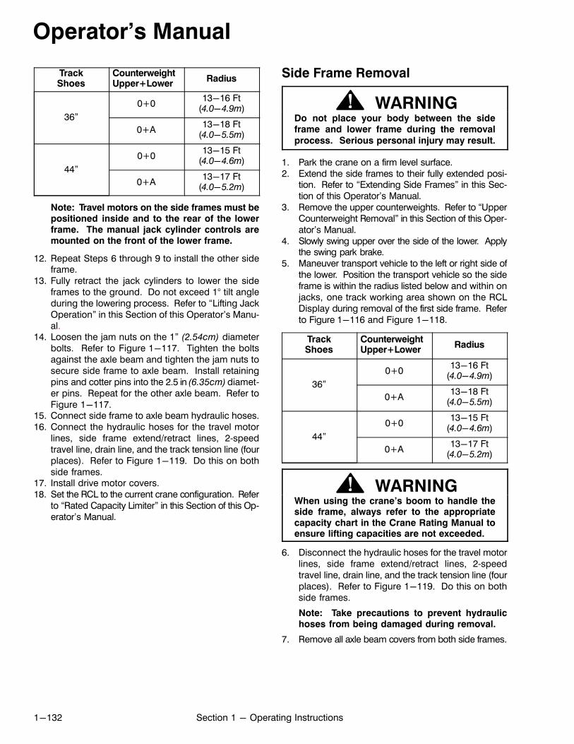
Operator's Manual
1-132 Section 1 - Operating Instructions
TrackShoes
CounterweightUpper+Lower
Radius
36”
0+013-16 Ft
(4.0-4.9m)
0+A13-18 Ft
(4.0-5.5m)
44”
0+013-15 Ft
(4.0-4.6m)
0+A13-17 Ft
(4.0-5.2m)
Note: Travel motors on the side frames must bepositioned inside and to the rear of the lowerframe. The manual jack cylinder controls aremounted on the front of the lower frame.
12. Repeat Steps 6 through 9 to install the other sideframe.
13. Fully retract the jack cylinders to lower the sideframes to the ground. Do not exceed 1° tilt angleduring the lowering process. Refer to “Lifting JackOperation” in this Section of this Operator's Manual.
14. Loosen the jam nuts on the 1” (2.54cm) diameterbolts. Refer to Figure 1-117. Tighten the boltsagainst the axle beam and tighten the jam nuts tosecure side frame to axle beam. Install retainingpins and cotter pins into the 2.5 in (6.35cm) diameter pins. Repeat for the other axle beam. Refer toFigure 1-117.
15. Connect side frame to axle beam hydraulic hoses.16. Connect the hydraulic hoses for the travel motor
lines, side frame extend/retract lines, 2‐speedtravel line, drain line, and the track tension line (fourplaces). Refer to Figure 1-119. Do this on bothside frames.
17. Install drive motor covers.18. Set the RCL to the current crane configuration. Refer
to “Rated Capacity Limiter” in this Section of this Operator's Manual.
Side Frame Removal
WARNINGDo not place your body between the sideframe and lower frame during the removal
process. Serious personal injury may result.
1. Park the crane on a firm level surface.2. Extend the side frames to their fully extended posi
tion. Refer to “Extending Side Frames” in this Section of this Operator's Manual.
3. Remove the upper counterweights. Refer to “UpperCounterweight Removal” in this Section of this Operator's Manual.
4. Slowly swing upper over the side of the lower. Applythe swing park brake.
5. Maneuver transport vehicle to the left or right side ofthe lower. Position the transport vehicle so the sideframe is within the radius listed below and within onjacks, one track working area shown on the RCLDisplay during removal of the first side frame. Referto Figure 1-116 and Figure 1-118.
TrackShoes
CounterweightUpper+Lower
Radius
36”
0+013-16 Ft
(4.0-4.9m)
0+A13-18 Ft
(4.0-5.5m)
44”
0+013-15 Ft
(4.0-4.6m)
0+A13-17 Ft
(4.0-5.2m)
WARNINGWhen using the crane's boom to handle theside frame, always refer to the appropriatecapacity chart in the Crane Rating Manual toensure lifting capacities are not exceeded.
6. Disconnect the hydraulic hoses for the travel motorlines, side frame extend/retract lines, 2‐speedtravel line, drain line, and the track tension line (fourplaces). Refer to Figure 1-119. Do this on bothside frames.
Note: Take precautions to prevent hydraulichoses from being damaged during removal.
7. Remove all axle beam covers from both side frames.
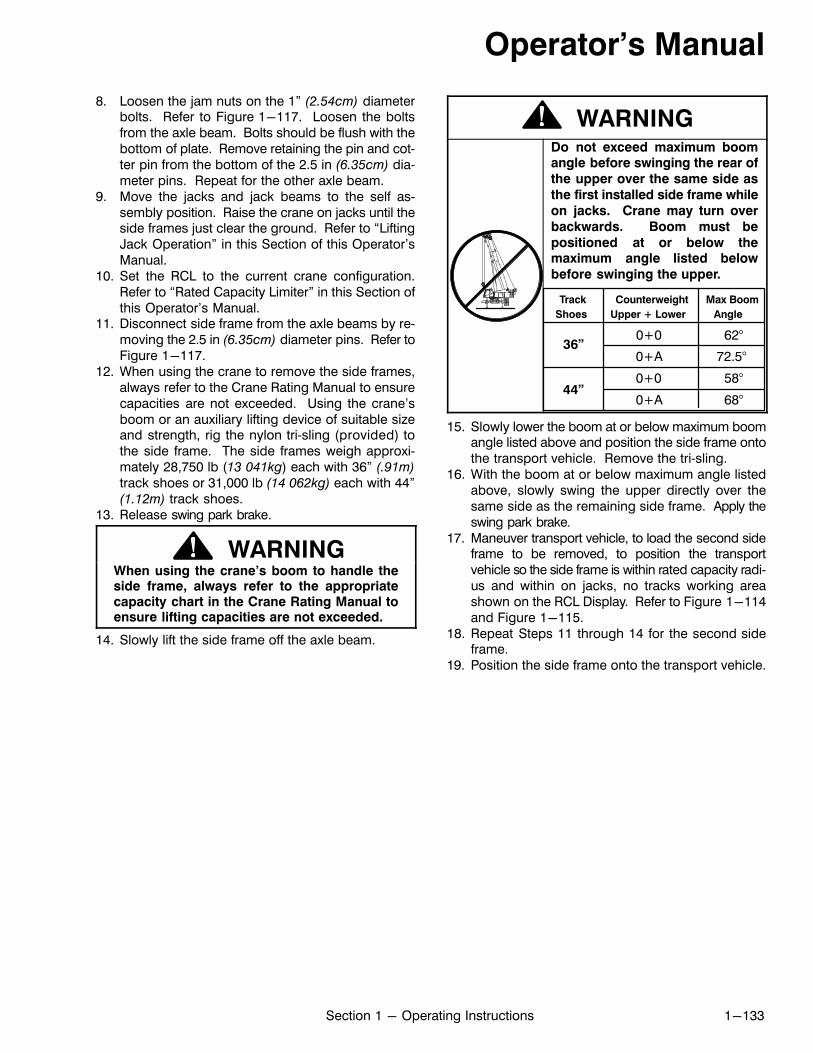
Operator's Manual
1-133Section 1 - Operating Instructions
8. Loosen the jam nuts on the 1” (2.54cm) diameterbolts. Refer to Figure 1-117. Loosen the boltsfrom the axle beam. Bolts should be flush with thebottom of plate. Remove retaining the pin and cotter pin from the bottom of the 2.5 in (6.35cm) diameter pins. Repeat for the other axle beam.
9. Move the jacks and jack beams to the self assembly position. Raise the crane on jacks until theside frames just clear the ground. Refer to “LiftingJack Operation” in this Section of this Operator'sManual.
10. Set the RCL to the current crane configuration.Refer to “Rated Capacity Limiter” in this Section ofthis Operator's Manual.
11. Disconnect side frame from the axle beams by removing the 2.5 in (6.35cm) diameter pins. Refer toFigure 1-117.
12. When using the crane to remove the side frames,always refer to the Crane Rating Manual to ensurecapacities are not exceeded. Using the crane'sboom or an auxiliary lifting device of suitable sizeand strength, rig the nylon tri‐sling (provided) tothe side frame. The side frames weigh approximately 28,750 lb (13 041kg) each with 36” (.91m)
track shoes or 31,000 lb (14 062kg) each with 44”(1.12m) track shoes.
13. Release swing park brake.
WARNINGWhen using the crane's boom to handle theside frame, always refer to the appropriatecapacity chart in the Crane Rating Manual toensure lifting capacities are not exceeded.
14. Slowly lift the side frame off the axle beam.
WARNING
Track Counterweight Max Boom
Shoes Upper + Lower Angle
0+0 62°
0+A 72.5°
0+0 58°
0+A 68°
Do not exceed maximum boomangle before swinging the rear of
the upper over the same side as
the first installed side frame while
on jacks. Crane may turn over
backwards. Boom must be
positioned at or below themaximum angle listed below
before swinging the upper.
36”
44”
15. Slowly lower the boom at or below maximum boomangle listed above and position the side frame ontothe transport vehicle. Remove the tri‐sling.
16. With the boom at or below maximum angle listedabove, slowly swing the upper directly over thesame side as the remaining side frame. Apply theswing park brake.
17. Maneuver transport vehicle, to load the second sideframe to be removed, to position the transportvehicle so the side frame is within rated capacity radius and within on jacks, no tracks working areashown on the RCL Display. Refer to Figure 1-114and Figure 1-115.
18. Repeat Steps 11 through 14 for the second sideframe.
19. Position the side frame onto the transport vehicle.
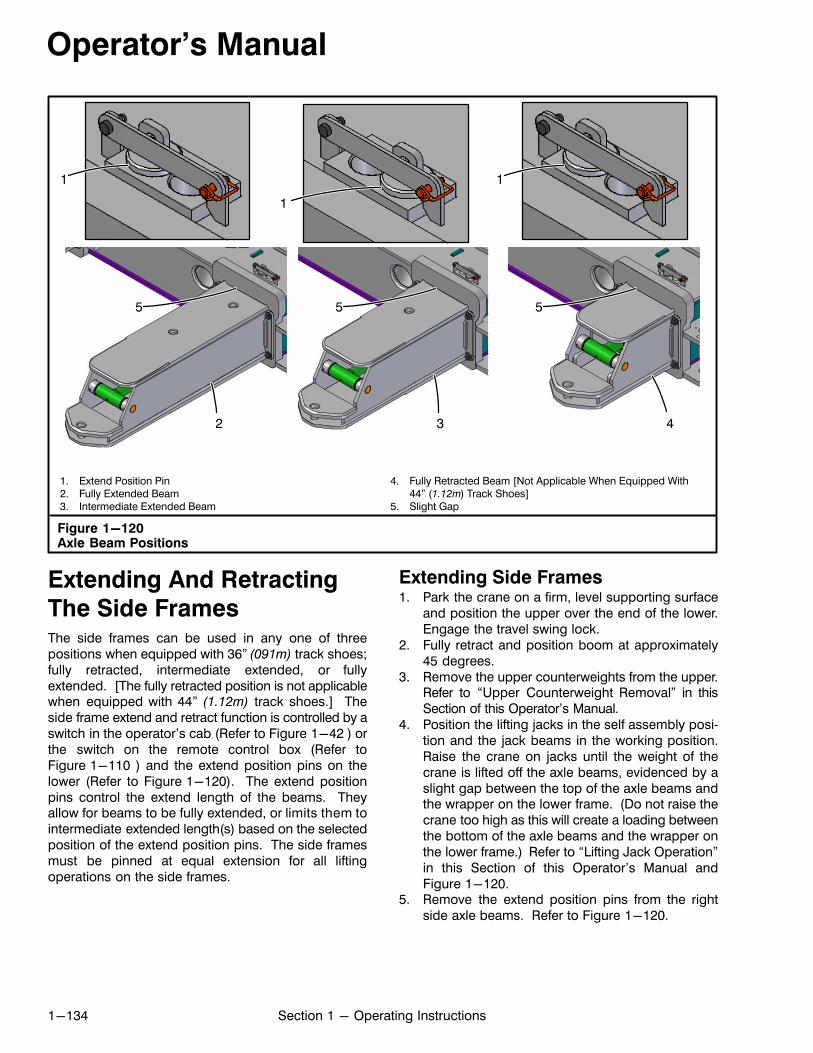
Operator's Manual
1-134 Section 1 - Operating Instructions
Figure 1-120Axle Beam Positions
1. Extend Position Pin2. Fully Extended Beam3. Intermediate Extended Beam
4. Fully Retracted Beam [Not Applicable When Equipped With44” (1.12m) Track Shoes]
5. Slight Gap
1
2 3 4
1
1
5 5 5
Extending And Retracting
The Side FramesThe side frames can be used in any one of threepositions when equipped with 36” (091m) track shoes;fully retracted, intermediate extended, or fullyextended. [The fully retracted position is not applicablewhen equipped with 44” (1.12m) track shoes.] Theside frame extend and retract function is controlled by aswitch in the operator's cab (Refer to Figure 1-42 ) orthe switch on the remote control box (Refer toFigure 1-110 ) and the extend position pins on thelower (Refer to Figure 1-120). The extend positionpins control the extend length of the beams. Theyallow for beams to be fully extended, or limits them tointermediate extended length(s) based on the selectedposition of the extend position pins. The side framesmust be pinned at equal extension for all liftingoperations on the side frames.
Extending Side Frames1. Park the crane on a firm, level supporting surface
and position the upper over the end of the lower.Engage the travel swing lock.
2. Fully retract and position boom at approximately45 degrees.
3. Remove the upper counterweights from the upper.Refer to “Upper Counterweight Removal” in thisSection of this Operator's Manual.
4. Position the lifting jacks in the self assembly position and the jack beams in the working position.Raise the crane on jacks until the weight of thecrane is lifted off the axle beams, evidenced by aslight gap between the top of the axle beams andthe wrapper on the lower frame. (Do not raise thecrane too high as this will create a loading betweenthe bottom of the axle beams and the wrapper onthe lower frame.) Refer to “Lifting Jack Operation”in this Section of this Operator's Manual andFigure 1-120.
5. Remove the extend position pins from the rightside axle beams. Refer to Figure 1-120.
Operator's Manual
1-135Section 1 - Operating Instructions
WARNINGWhen making lifts on side frames, all axlebeams must be equally extended; all fully
retracted [fully retracted position is not
applicable when equipped with 44” (1.12m)
track shoes], all intermediate extended, or all
fully extended. Failure to do so will cause a
loss of stability and possible crane damageand/or personal injury.
6. Push the side frame extend switch to the “Extend” position and hold until the right side axle
beams are extended to desired position. Releasethe switch.
7. Install the extend position pins in the appropriateextended position. Refer to Figure 1-120.
8. Remove the extend position pins from the left sideaxle beams. Refer to Figure 1-120.
9. Push the side frame extend switch to the “Extend” position and hold until the left side axle beams
are extended to desired position. Release theswitch.
10. Install the extend position pins in the appropriateextended position. Refer to Figure 1-120.
11. Lower the crane and completely retract lifting jackcylinders. Properly remove and store pontoonsand position jack cylinders and beams in the working position. Refer to “Lifting Jack Operation” inthis Section of this Operator's Manual.
12. Configure upper counterweights to an allowableconfiguration per the current side frame position.Refer to the Crane Rating Manual to determinethe allowable counterweight combinations. Install upper counterweights. Refer to “Upper Counterweight Installation” in this Section of this Operator's Manual.
13. Set the RCL to the current crane configuration. Referto “Rated Capacity Limiter” in this Section of this Operator's Manual.
Retracting Side Frames1. Park the crane on a firm, level supporting surface
and position the upper over the end of the lower.Engage the travel swing lock.
2. Properly store the fly if equipped. Refer to Section4 of this Operator's Manual.
3. Remove the upper counterweights from the upper.Refer to “Upper Counterweight Removal” in thisSection of this Operator's Manual.
4. Fully retract and position boom at approximately45 degrees.
5. Position the lifting jacks in the self assembly position and the jack beams in the working position.Raise the crane on jacks until the weight of thecrane is lifted off the axle beams, evidenced by aslight gap between the top of the axle beams andthe wrapper on the lower frame. (Do not raise thecrane too high as this will create a loading betweenthe bottom of the axle beams and the wrapper onthe lower frame.) Refer to “Lifting Jack Operation”in this Section of this Operator's Manual andFigure 1-120.
6. Remove the extend position pins from the rightside axle beams. Refer to Figure 1-120.
WARNINGWhen making lifts on side frames, all axlebeams must be equally extended; all fully
retracted [fully retracted position is not
applicable when equipped with 44” (1.12m)
track shoes], all intermediate extended, or all
fully extended. Failure to do so will cause a
loss of stability and possible crane damageand/or personal injury.
7. Push the side frame extend switch to the “Retract” position and hold until the right side axle
beams are retracted to desired position. Releasethe switch.
8. Install the extend position pins in the appropriateposition. Refer to Figure 1-120.
9. Remove the extend position pins from the left sideaxle beam. Refer to Figure 1-120.
10. Push the side frame extend switch to the “Retract” position and hold until the left side axle beams
are retracted to desired position. Release theswitch.
11. Install the extend position pins in the appropriateposition. Refer to Figure 1-120.
12. Lower the crane and completely retract lifting jackcylinders. Properly remove and store pontoonsand position jack cylinders and beams in the working position. Refer to “Lifting Jack Operation” inthis Section of this Operator's Manual.
13. Configure upper counterweights to an allowableconfiguration per the current side frame position.Refer to the Crane Rating Manual to determinethe allowable counterweight combinations. Install the upper counterweights. Refer to “UpperCounterweight Installation” in this Section of thisOperator's Manual.
14. Set the RCL to the current crane configuration. Referto “Rated Capacity Limiter” in this Section of this Operator's Manual.

Operator's Manual
1-136 Section 1 - Operating Instructions
Figure 1-121Counterweight Installation
1
2
1. “A” Counterweight Lifting Shackles2. “A” Counterweight W/Cylinders
3. Connecting Link4. Lock Pin
5. “B” Counterweight6. “C” Counterweight
4
3
Component Weight
lb kg
“A” CTWT W/Cylinders 19,000 (8 618)“B” CTWT 16,000 (7 257)
“C” CTWT 16,000 (7 257)
5
6
2
Upper CounterweightAssembly, Installation, AndRemovalThe upper counterweights can be assembled with thecrane. They are installed and removed using the coun
terweight installation/removal cylinders. They can beinstalled to the upper in “A”, “AB”, or “ABC” combinations depending upon the desired capacities.Refer to the Crane Rating Manual to determine theallowable counterweight combinations.
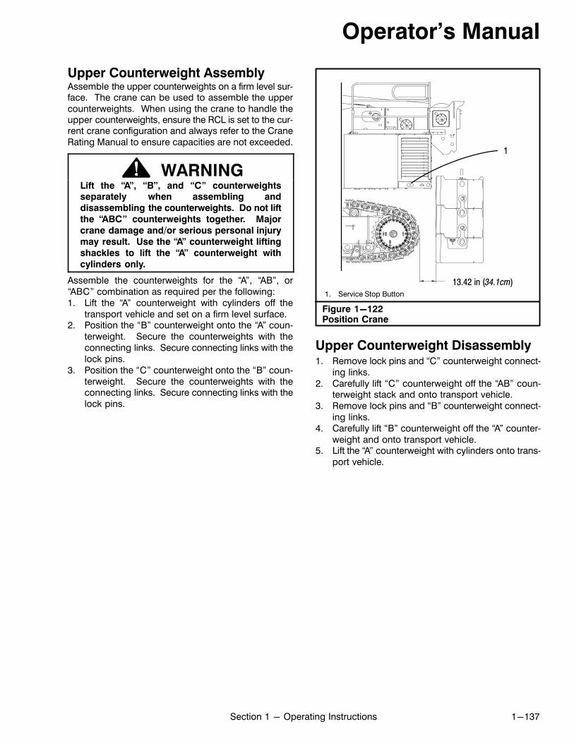
Operator's Manual
1-137Section 1 - Operating Instructions
Upper Counterweight AssemblyAssemble the upper counterweights on a firm level surface. The crane can be used to assemble the uppercounterweights. When using the crane to handle theupper counterweights, ensure the RCL is set to the current crane configuration and always refer to the CraneRating Manual to ensure capacities are not exceeded.
WARNINGLift the “A”, “B”, and “C” counterweightsseparately when assembling and
disassembling the counterweights. Do not lift
the “ABC” counterweights together. Major
crane damage and/or serious personal injury
may result. Use the “A” counterweight lifting
shackles to lift the “A” counterweight with
cylinders only.
Assemble the counterweights for the “A”, “AB”, or“ABC” combination as required per the following:1. Lift the “A” counterweight with cylinders off the
transport vehicle and set on a firm level surface.2. Position the “B” counterweight onto the “A” coun
terweight. Secure the counterweights with theconnecting links. Secure connecting links with thelock pins.
3. Position the “C” counterweight onto the “B” counterweight. Secure the counterweights with theconnecting links. Secure connecting links with thelock pins.
Figure 1-122Position Crane
13.42 in (34.1cm)1. Service Stop Button
1
Upper Counterweight Disassembly1. Remove lock pins and “C” counterweight connect
ing links.2. Carefully lift “C” counterweight off the “AB” coun
terweight stack and onto transport vehicle.3. Remove lock pins and “B” counterweight connect
ing links.4. Carefully lift “B” counterweight off the “A” counter
weight and onto transport vehicle.5. Lift the “A” counterweight with cylinders onto trans
port vehicle.
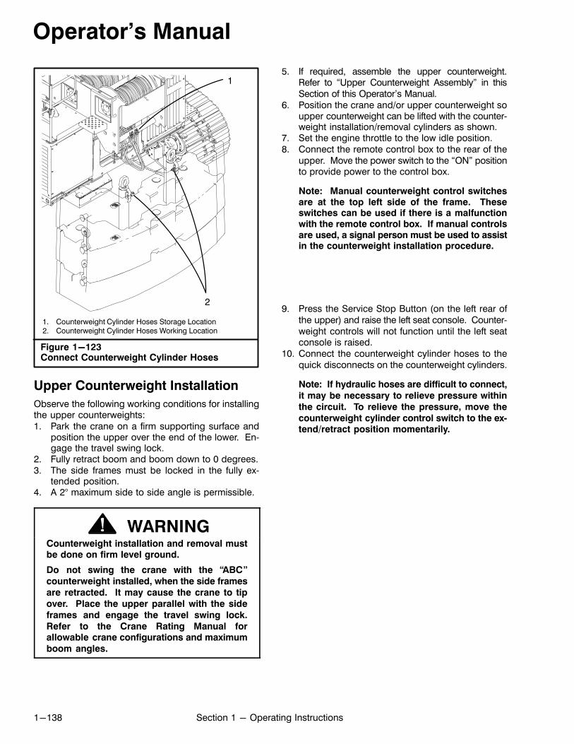
Operator's Manual
1-138 Section 1 - Operating Instructions
Figure 1-123Connect Counterweight Cylinder Hoses
1. Counterweight Cylinder Hoses Storage Location2. Counterweight Cylinder Hoses Working Location
1
2
Upper Counterweight Installation
Observe the following working conditions for installingthe upper counterweights:1. Park the crane on a firm supporting surface and
position the upper over the end of the lower. Engage the travel swing lock.
2. Fully retract boom and boom down to 0 degrees.3. The side frames must be locked in the fully ex
tended position.4. A 2° maximum side to side angle is permissible.
WARNINGCounterweight installation and removal mustbe done on firm level ground.
Do not swing the crane with the “ABC”
counterweight installed, when the side frames
are retracted. It may cause the crane to tip
over. Place the upper parallel with the side
frames and engage the travel swing lock.
Refer to the Crane Rating Manual forallowable crane configurations and maximum
boom angles.
5. If required, assemble the upper counterweight.Refer to “Upper Counterweight Assembly” in thisSection of this Operator's Manual.
6. Position the crane and/or upper counterweight soupper counterweight can be lifted with the counterweight installation/removal cylinders as shown.
7. Set the engine throttle to the low idle position.8. Connect the remote control box to the rear of the
upper. Move the power switch to the “ON” positionto provide power to the control box.
Note: Manual counterweight control switchesare at the top left side of the frame. Theseswitches can be used if there is a malfunctionwith the remote control box. If manual controlsare used, a signal person must be used to assistin the counterweight installation procedure.
9. Press the Service Stop Button (on the left rear ofthe upper) and raise the left seat console. Counterweight controls will not function until the left seatconsole is raised.
10. Connect the counterweight cylinder hoses to thequick disconnects on the counterweight cylinders.
Note: If hydraulic hoses are difficult to connect,
it may be necessary to relieve pressure within
the circuit. To relieve the pressure, move the
counterweight cylinder control switch to the extend/retract position momentarily.
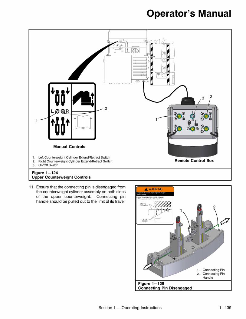
Operator's Manual
1-139Section 1 - Operating Instructions
1. Left Counterweight Cylinder Extend/Retract Switch2. Right Counterweight Cylinder Extend/Retract Switch3. On/Off Switch
Figure 1-124Upper Counterweight Controls
1
2
Remote Control Box
Manual Controls
3
1
2
11. Ensure that the connecting pin is disengaged fromthe counterweight cylinder assembly on both sidesof the upper counterweight. Connecting pinhandle should be pulled out to the limit of its travel.
Figure 1-125Connecting Pin Disengaged
1. Connecting Pin2. Connecting Pin
Handle
12Ï
ÏÏÏÏÏÏ
ÏÏÏÏÏÏÏÏ
ÏÏÏÏÏÏ
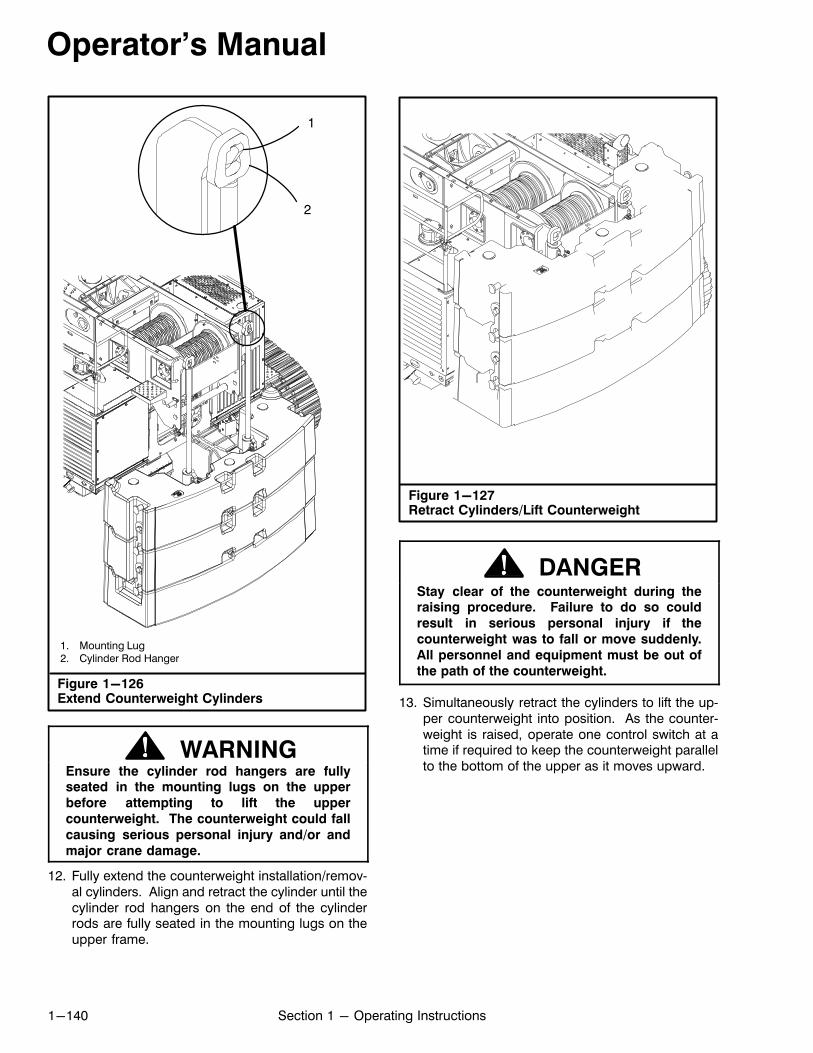
Operator's Manual
1-140 Section 1 - Operating Instructions
Figure 1-126Extend Counterweight Cylinders
1. Mounting Lug2. Cylinder Rod Hanger
1
2
WARNINGEnsure the cylinder rod hangers are fullyseated in the mounting lugs on the upper
before attempting to lift the upper
counterweight. The counterweight could fall
causing serious personal injury and/or and
major crane damage.
12. Fully extend the counterweight installation/removal cylinders. Align and retract the cylinder until thecylinder rod hangers on the end of the cylinderrods are fully seated in the mounting lugs on theupper frame.
Figure 1-127Retract Cylinders/Lift Counterweight
DANGERStay clear of the counterweight during theraising procedure. Failure to do so could
result in serious personal injury if the
counterweight was to fall or move suddenly.
All personnel and equipment must be out of
the path of the counterweight.
13. Simultaneously retract the cylinders to lift the upper counterweight into position. As the counterweight is raised, operate one control switch at atime if required to keep the counterweight parallelto the bottom of the upper as it moves upward.
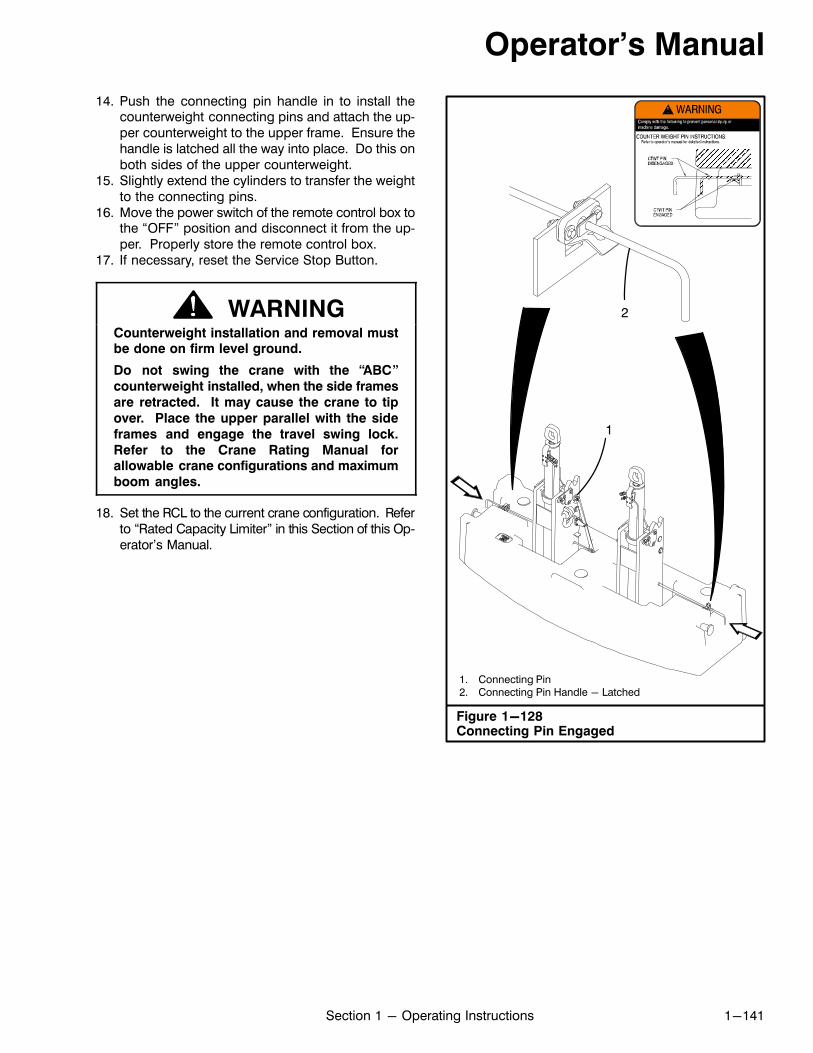
Operator's Manual
1-141Section 1 - Operating Instructions
14. Push the connecting pin handle in to install thecounterweight connecting pins and attach the upper counterweight to the upper frame. Ensure thehandle is latched all the way into place. Do this onboth sides of the upper counterweight.
15. Slightly extend the cylinders to transfer the weightto the connecting pins.
16. Move the power switch of the remote control box tothe “OFF” position and disconnect it from the upper. Properly store the remote control box.
17. If necessary, reset the Service Stop Button.
WARNINGCounterweight installation and removal mustbe done on firm level ground.
Do not swing the crane with the “ABC”
counterweight installed, when the side frames
are retracted. It may cause the crane to tip
over. Place the upper parallel with the side
frames and engage the travel swing lock.
Refer to the Crane Rating Manual forallowable crane configurations and maximum
boom angles.
18. Set the RCL to the current crane configuration. Referto “Rated Capacity Limiter” in this Section of this Operator's Manual.
Figure 1-128Connecting Pin Engaged
1. Connecting Pin2. Connecting Pin Handle - Latched
1
2
ÏÏÏÏÏÏÏÏÏÏÏÏÏÏ
ÏÏÏÏÏÏ
Operator's Manual
1-142 Section 1 - Operating Instructions
Upper Counterweight Removal
Observe the following working conditions for removingthe upper counterweights:1. Park the crane on a firm supporting surface and
position the upper over the end of the lower. Engage the travel swing lock.
2. Properly store the fly if equipped. Refer to Section4 of this Operator's Manual.
3. A 2° maximum side to side angle is permissible.4. The side frames must be locked in the fully ex
tended position.
WARNINGCounterweight installation and removal mustbe done on firm level ground.
Do not swing the crane with the “ABC”
counterweight installed, when the side frames
are retracted. It may cause the crane to tip
over. Place the upper parallel with the side
frames and engage the travel swing lock.
Refer to the Crane Rating Manual forallowable crane configurations and maximum
boom angles.
5. Fully retract the boom and boom down to 0 degrees.
6. Press the Service Stop Button (on the left rear ofthe upper, refer to Figure 1-122) and raise the leftseat console. Counterweight controls will not function until the left seat console is raised.
7. If not already connected, connect the counterweight cylinder hoses to the quick disconnects onthe counterweight cylinders. Refer toFigure 1-123.
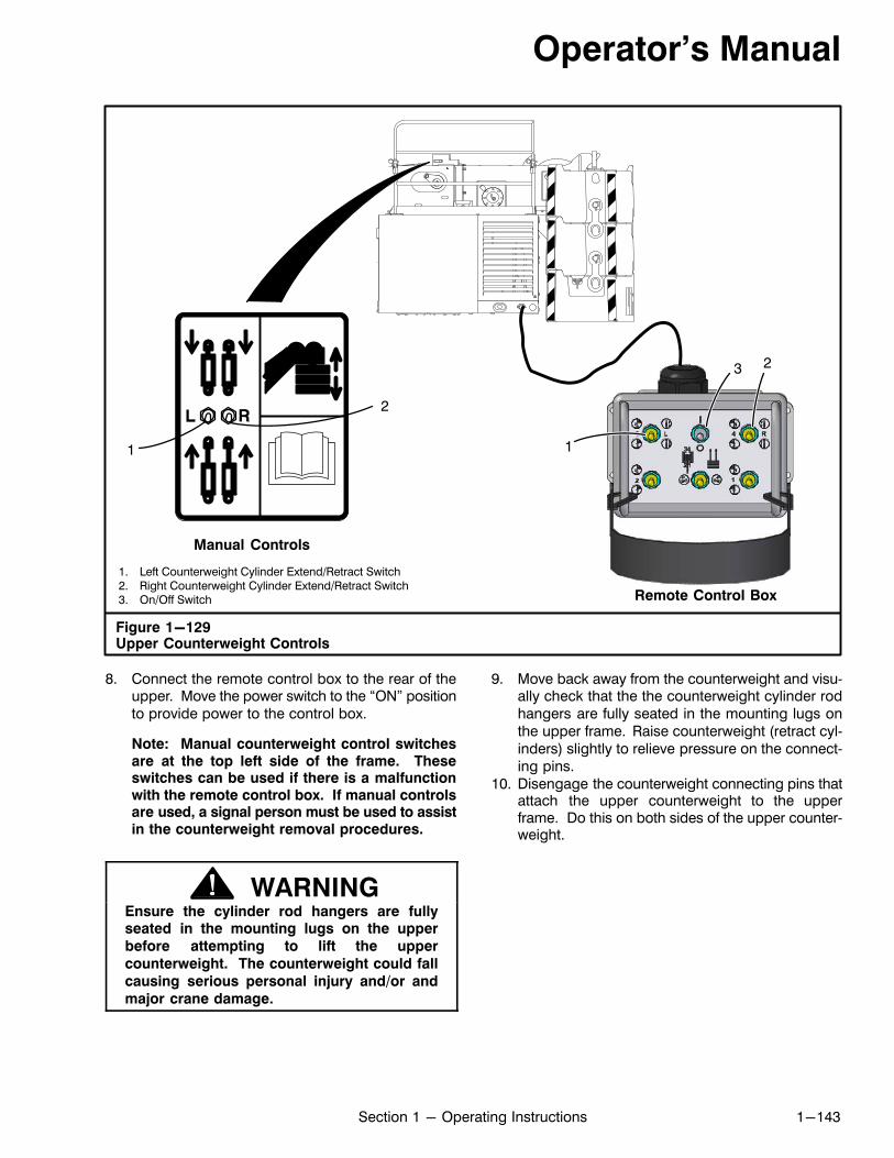
Operator's Manual
1-143Section 1 - Operating Instructions
1. Left Counterweight Cylinder Extend/Retract Switch2. Right Counterweight Cylinder Extend/Retract Switch3. On/Off Switch
Figure 1-129Upper Counterweight Controls
1
2
Remote Control Box
Manual Controls
3
1
2
8. Connect the remote control box to the rear of theupper. Move the power switch to the “ON” positionto provide power to the control box.
Note: Manual counterweight control switchesare at the top left side of the frame. Theseswitches can be used if there is a malfunctionwith the remote control box. If manual controlsare used, a signal person must be used to assistin the counterweight removal procedures.
WARNINGEnsure the cylinder rod hangers are fullyseated in the mounting lugs on the upper
before attempting to lift the upper
counterweight. The counterweight could fall
causing serious personal injury and/or and
major crane damage.
9. Move back away from the counterweight and visually check that the the counterweight cylinder rodhangers are fully seated in the mounting lugs onthe upper frame. Raise counterweight (retract cylinders) slightly to relieve pressure on the connecting pins.
10. Disengage the counterweight connecting pins thatattach the upper counterweight to the upperframe. Do this on both sides of the upper counterweight.
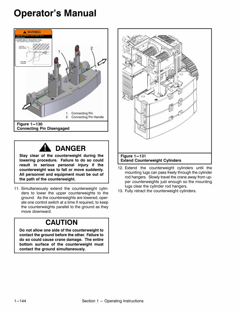
Operator's Manual
1-144 Section 1 - Operating Instructions
Figure 1-130Connecting Pin Disengaged
1. Connecting Pin2. Connecting Pin Handle
12
ÏÏÏÏÏÏÏÏÏÏÏÏÏÏÏÏ
ÏÏÏÏÏÏÏÏ
DANGERStay clear of the counterweight during thelowering procedure. Failure to do so could
result in serious personal injury if the
counterweight was to fall or move suddenly.
All personnel and equipment must be out of
the path of the counterweight.
11. Simultaneously extend the counterweight cylinders to lower the upper counterweights to theground. As the counterweights are lowered, operate one control switch at a time if required, to keepthe counterweights parallel to the ground as theymove downward.
CAUTIONDo not allow one side of the counterweight tocontact the ground before the other. Failure to
do so could cause crane damage. The entire
bottom surface of the counterweight must
contact the ground simultaneously.
Figure 1-131Extend Counterweight Cylinders
12. Extend the counterweight cylinders until themounting lugs can pass freely through the cylinderrod hangers. Slowly travel the crane away from upper counterweights just enough so the mountinglugs clear the cylinder rod hangers.
13. Fully retract the counterweight cylinders.
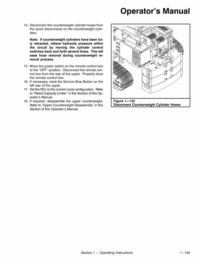
Operator's Manual
1-145Section 1 - Operating Instructions
14. Disconnect the counterweight cylinder hoses fromthe quick disconnects on the counterweight cylinders.
Note: If counterweight cylinders have been ful
ly retracted, relieve hydraulic pressure within
the circuit by moving the cylinder control
switches back and forth several times. This will
ease hose removal during counterweight re
moval process.
15. Move the power switch on the remote control boxto the “OFF” position. Disconnect the remote control box from the rear of the upper. Properly storethe remote control box.
16. If necessary, reset the Service Stop Button on theleft rear of the upper.
17. Set the RCL to the current crane configuration. Referto “Rated Capacity Limiter” in this Section of this Operator's Manual.
18. If required, disassemble the upper counterweight.Refer to “Upper Counterweight Disassembly” in thisSection of this Operator's Manual.
Figure 1-132Disconnect Counterweight Cylinder Hoses
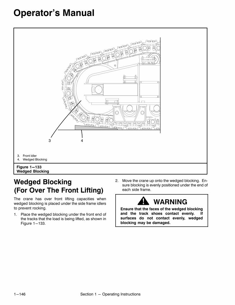
Operator's Manual
1-146 Section 1 - Operating Instructions
3. Front Idler4. Wedged Blocking
Figure 1-133Wedged Blocking
3 4
Wedged Blocking
(For Over The Front Lifting)The crane has over front lifting capacities whenwedged blocking is placed under the side frame idlersto prevent rocking.
1. Place the wedged blocking under the front end ofthe tracks that the load is being lifted, as shown inFigure 1-133.
2. Move the crane up onto the wedged blocking. Ensure blocking is evenly positioned under the end ofeach side frame.
WARNINGEnsure that the faces of the wedged blockingand the track shoes contact evenly. If
surfaces do not contact evenly, wedged
blocking may be damaged.
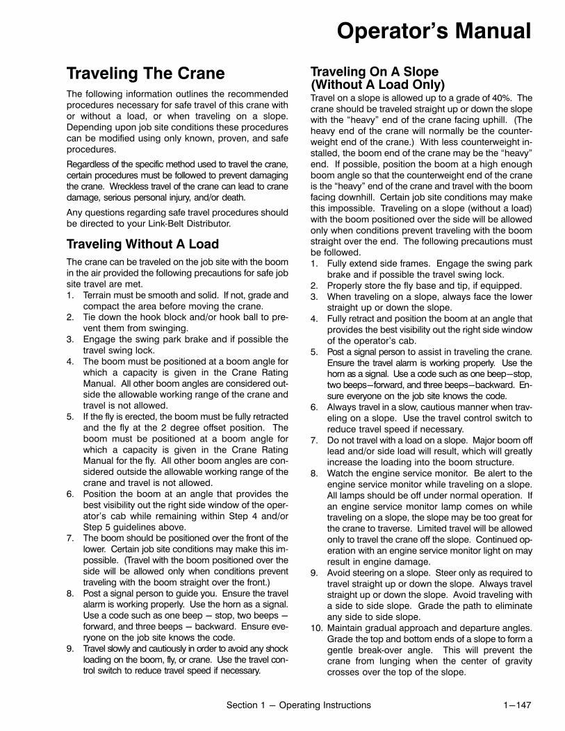
Operator's Manual
1-147Section 1 - Operating Instructions
Traveling The CraneThe following information outlines the recommendedprocedures necessary for safe travel of this crane withor without a load, or when traveling on a slope.Depending upon job site conditions these procedurescan be modified using only known, proven, and safeprocedures.
Regardless of the specific method used to travel the crane,certain procedures must be followed to prevent damagingthe crane. Wreckless travel of the crane can lead to cranedamage, serious personal injury, and/or death.
Any questions regarding safe travel procedures shouldbe directed to your Link‐Belt Distributor.
Traveling Without A Load
The crane can be traveled on the job site with the boomin the air provided the following precautions for safe jobsite travel are met.1. Terrain must be smooth and solid. If not, grade and
compact the area before moving the crane.2. Tie down the hook block and/or hook ball to pre
vent them from swinging.3. Engage the swing park brake and if possible the
travel swing lock.4. The boom must be positioned at a boom angle for
which a capacity is given in the Crane RatingManual. All other boom angles are considered outside the allowable working range of the crane andtravel is not allowed.
5. If the fly is erected, the boom must be fully retractedand the fly at the 2 degree offset position. Theboom must be positioned at a boom angle forwhich a capacity is given in the Crane RatingManual for the fly. All other boom angles are considered outside the allowable working range of thecrane and travel is not allowed.
6. Position the boom at an angle that provides thebest visibility out the right side window of the operator's cab while remaining within Step 4 and/orStep 5 guidelines above.
7. The boom should be positioned over the front of thelower. Certain job site conditions may make this impossible. (Travel with the boom positioned over theside will be allowed only when conditions preventtraveling with the boom straight over the front.)
8. Post a signal person to guide you. Ensure the travelalarm is working properly. Use the horn as a signal.Use a code such as one beep - stop, two beeps -forward, and three beeps - backward. Ensure everyone on the job site knows the code.
9. Travel slowly and cautiously in order to avoid any shockloading on the boom, fly, or crane. Use the travel control switch to reduce travel speed if necessary.
Traveling On A Slope(Without A Load Only)Travel on a slope is allowed up to a grade of 40%. Thecrane should be traveled straight up or down the slopewith the “heavy” end of the crane facing uphill. (Theheavy end of the crane will normally be the counterweight end of the crane.) With less counterweight installed, the boom end of the crane may be the “heavy”end. If possible, position the boom at a high enoughboom angle so that the counterweight end of the craneis the “heavy” end of the crane and travel with the boomfacing downhill. Certain job site conditions may makethis impossible. Traveling on a slope (without a load)with the boom positioned over the side will be allowedonly when conditions prevent traveling with the boomstraight over the end. The following precautions mustbe followed.1. Fully extend side frames. Engage the swing park
brake and if possible the travel swing lock.2. Properly store the fly base and tip, if equipped.3. When traveling on a slope, always face the lower
straight up or down the slope.4. Fully retract and position the boom at an angle that
provides the best visibility out the right side windowof the operator's cab.
5. Post a signal person to assist in traveling the crane.Ensure the travel alarm is working properly. Use thehorn as a signal. Use a code such as one beep-stop,two beeps-forward, and three beeps-backward. Ensure everyone on the job site knows the code.
6. Always travel in a slow, cautious manner when traveling on a slope. Use the travel control switch toreduce travel speed if necessary.
7. Do not travel with a load on a slope. Major boom offlead and/or side load will result, which will greatlyincrease the loading into the boom structure.
8. Watch the engine service monitor. Be alert to theengine service monitor while traveling on a slope.All lamps should be off under normal operation. Ifan engine service monitor lamp comes on whiletraveling on a slope, the slope may be too great forthe crane to traverse. Limited travel will be allowedonly to travel the crane off the slope. Continued operation with an engine service monitor light on mayresult in engine damage.
9. Avoid steering on a slope. Steer only as required totravel straight up or down the slope. Always travelstraight up or down the slope. Avoid traveling witha side to side slope. Grade the path to eliminateany side to side slope.
10. Maintain gradual approach and departure angles.Grade the top and bottom ends of a slope to form agentle break‐over angle. This will prevent thecrane from lunging when the center of gravitycrosses over the top of the slope.
Operator's Manual
1-148 Section 1 - Operating Instructions
Traveling With A Load (Pick & Carry)
The Crane Rating Manual lists the allowable capacitiesfor traveling with a load (pick and carry) operations.Use these capacities only for all pick and carry operations. The boom should be positioned over the front ofthe lower. If the load was lifted over the side, swing theload over the front before traveling. Certain job siteconditions may make this impossible. (Pick and carrywith the boom positioned over the side will be allowedonly when conditions prevent traveling with the boomstraight over the front.) The following precautions mustbe followed while traveling with a load.1. Engage the swing park brake and if possible the
travel swing lock.2. Travel only on a smooth level surface. If a smooth
level route is not available, don't travel with a suspended load. Grade and compact the route to provide a firm, smooth, and level path. If it is not possible to grade the route, move the load by stepping. Park the crane on a level area, lift the load,swing around, and set it down ahead of the crane.Travel the unloaded crane beyond the load, levelthe crane, lift the load, swing, and set it down farther along the route. Continue this procedure untilthe load is at its destination.
3. Boom must be extended in accordance with“Standard” or “A‐Max” boom modes.
4. Use hand lines to control the load and reduce loadswing.
5. Carry loads as close to the ground as possible.
6. Do not allow side swing of load.7. Don't attempt to carry loads which exceed the
crane's rating.8. Don't travel with a load on soft ground. If the crane
sinks into the ground, stability can be affected tothe point of tipping the crane.
9. Keep all personnel clear of the crane and load. Beprepared to set the load down quickly at anytime incase of an emergency.
10. Position the boom at a boom angle/boom lengththat will give the greatest margin of safety. If theload was lifted at a long radius and the load is at ornear capacity for that radius, boom up/retractboom to obtain a greater lifting capacity (and thusa greater margin of safety) before starting travel.
11. Position the boom at an angle that provides thebest visibility out the right side window of the operator's cab while remaining within Step 10guidelines above.
12. Position a signal person to assist in traveling thecrane. Ensure the travel alarm is working properly.Use the horn as a signal. Use a code such as onebeep - stop, two beeps - forward, and three beeps- backward. Ensure everyone on the job site knowsthe code.
13. Travel slowly and cautiously in order to avoid shockloading on the boom, fly, or crane. Use the travelcontrol switch to reduce travel speed if necessary.Do not let the load swing out or to the side. Theload must be kept directly under the boom point atall times.
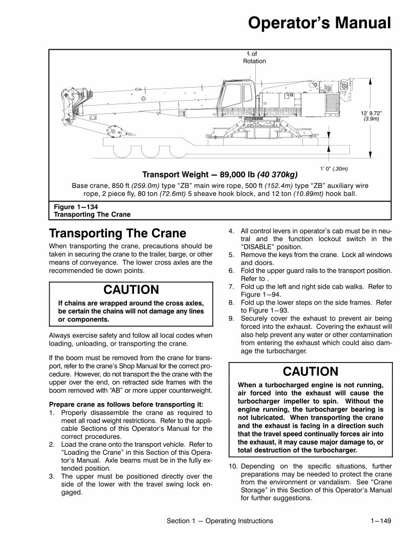
Operator's Manual
1-149Section 1 - Operating Instructions
Figure 1-134Transporting The Crane
Transport Weight - 89,000 lb (40 370kg)
Base crane, 850 ft (259.0m) type “ZB” main wire rope, 500 ft (152.4m) type “ZB” auxiliary wirerope, 2 piece fly, 80 ton (72.6mt) 5 sheave hook block, and 12 ton (10.89mt) hook ball.
ofRotation
12' 9.72”(3.9m)
1' 0” (.30m)
Transporting The CraneWhen transporting the crane, precautions should betaken in securing the crane to the trailer, barge, or othermeans of conveyance. The lower cross axles are therecommended tie down points.
CAUTIONIf chains are wrapped around the cross axles,be certain the chains will not damage any lines
or components.
Always exercise safety and follow all local codes whenloading, unloading, or transporting the crane.
If the boom must be removed from the crane for transport, refer to the crane's Shop Manual for the correct procedure. However, do not transport the the crane with theupper over the end, on retracted side frames with theboom removed with “AB” or more upper counterweight.
Prepare crane as follows before transporting it:
1. Properly disassemble the crane as required tomeet all road weight restrictions. Refer to the applicable Sections of this Operator's Manual for thecorrect procedures.
2. Load the crane onto the transport vehicle. Refer to“Loading the Crane” in this Section of this Operator's Manual. Axle beams must be in the fully extended position.
3. The upper must be positioned directly over theside of the lower with the travel swing lock engaged.
4. All control levers in operator's cab must be in neutral and the function lockout switch in the“DISABLE” position.
5. Remove the keys from the crane. Lock all windowsand doors.
6. Fold the upper guard rails to the transport position.Refer to .
7. Fold up the left and right side cab walks. Refer toFigure 1-94.
8. Fold up the lower steps on the side frames. Referto Figure 1-93.
9. Securely cover the exhaust to prevent air beingforced into the exhaust. Covering the exhaust willalso help prevent any water or other contaminationfrom entering the exhaust which could also damage the turbocharger.
CAUTIONWhen a turbocharged engine is not running,air forced into the exhaust will cause the
turbocharger impeller to spin. Without the
engine running, the turbocharger bearing is
not lubricated. When transporting the crane
and the exhaust is facing in a direction such
that the travel speed continually forces air into
the exhaust, it may cause major damage to, ortotal destruction of the turbocharger.
10. Depending on the specific situations, furtherpreparations may be needed to protect the cranefrom the environment or vandalism. See “CraneStorage” in this Section of this Operator's Manualfor further suggestions.
Operator's Manual
1-150 Section 1 - Operating Instructions
Towing The CraneAlways use good judgment and reliable equipmentwhen towing the crane. When making connections between the crane and towing vehicle, ensure none of theconnections will cause damage to either vehicle. Thetow lugs are the recommended connection points onthe crane. Refer to Figure 1-135.
Always exercise safety when towing the crane. Prepare the crane as follows before towing it.1. If equipped, store the fly base and tip on the boom.2. Swing the upper over the end of the lower and en
gage the travel swing lock.3. All boom sections must be fully retracted with the
boom at a 0° angle. Secure the hook block and/orhook ball to prevent excessive swinging.
4. The engine must be running and the travel leversengaged to assist in towing the crane.
Lifting The CraneThe entire crane (except the fly) can be lifted or thecomponents may be removed from the crane and liftedindividually. Refer to Figure 1-135 for the center ofgravity (CG) and weights for the entire crane and theindividual components. The following conditions andprecautions must be met before lifting the crane or removing any component.1. The crane must be parked on a firm level surface
with the travel swing lock engaged. The swingpark brake and 360° swing lock, if equipped, mustbe released.
2. Use lifting equipment, shackles, slings, chains,etc. of suitable size and strength. All lifting equipment must be inspected before lifting the crane.The inspection must be recorded and dated in accordance with current regulations.
3. Fold up the left and right side cab walks. Refer toFigure 1-94.
4. When lifting the entire crane (without fly), extendthe side frames to the intermediate position andinstall slings around the beams. Protect slingsfrom any sharp edges.
5. The weights and locations of all CG's include allpossible options (heaviest crane) except the flybase and fly tip. Use the CG's as a starting point.Center hoist line on the CG, lift a few inches (centi
meters) and adjust the hoist line to keep the crane/components level at all times.
6. Removal of any components from the crane willshift the CG of the entire crane. Adjust hoist line toaccount for the removal of any component.
7. Do not lift crane with fly attached to boom. Damage to the fly may result. Remove the fly from thecrane before lifting. Refer to Section 4 of this Operator's Manual for the correct procedures for removing the fly.
8. Use only properly attached nylon straps to lift flybase or fly tip to prevent damage to the component. Refer to Figure 1-10. Protect the strapsfrom sharp edges.
9. Do not allow the hoist lines to contact boom whilelifting crane. Damage to the boom may result.
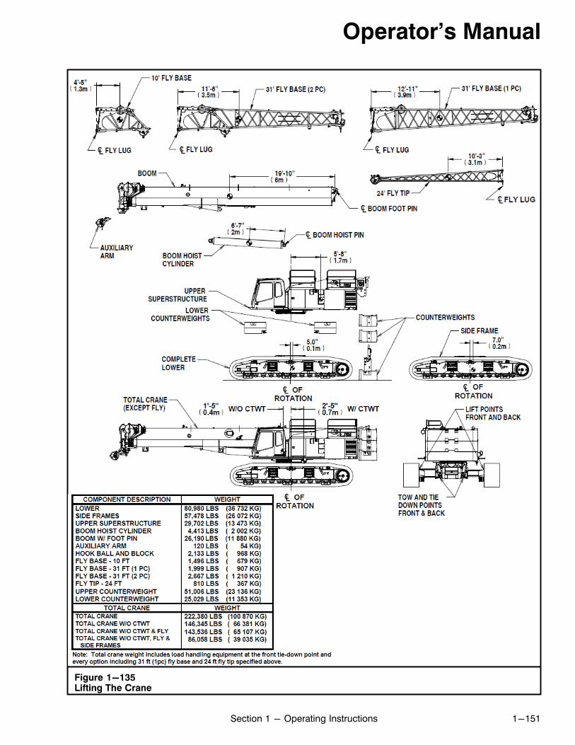
Figure 1-135Lifting The Crane
Operator's Manual
1-151Section 1 - Operating Instructions
Operator's Manual
1-152 Section 1 - Operating Instructions
Crane StorageAny time the crane is going to be left unattended, itshould be prepared so that it will not be damaged bythe elements, be an attraction to vandals, or a playthingfor children.
Short Term Storage1. Do not leave the crane where it will be a traffic haz
ard.2. Lower all loads to the ground.3. The boom can be left in the air provided that the
“Wind Restriction Guide” in the Crane RatingManual is adhered to. If the wind velocity exceedsthe Link‐Belt guidelines at any time during cranestorage, fully retract the boom and store the boomin the fully lowered position. Do not take chances.Refer to the Crane Rating Manual for wind speedand other applicable restrictions.
4. The travel swing lock must be engaged.5. Tie off the hook block and/or hook ball to keep the
winch wire ropes snug.6. All control levers must be in the neutral position
with the function lockout switch in the “DISABLE”position.
7. Block the tracks to prevent the crane from rolling.8. In cold weather, locate the crane where it will not
freeze to the ground.9. To preserve battery life, move the battery discon
nect switches to the off position.10. Remove the keys from the crane. Lock all windows
and doors.11. Prepare the engine as per the engine manufac
turer's manual. Ensure antifreeze protection is sufficient to prevent the engine from freezing. If antifreeze protection is not adequate, completely drainthe engine block.
Long Term Storage1. Store the crane inside a building if possible.2. The boom can be left in the air provided that the
“Wind Restriction Guide” in the Crane RatingManual is adhered to. If the wind velocity exceedsthe Link‐Belt guidelines at any time during cranestorage, fully retract the boom and store the boomin the fully lowered position. Do not take chances.Refer to the Crane Rating Manual for wind speedand other applicable restrictions.
3. Thoroughly clean the crane.4. Touch up any spots where paint has chipped. This
will prevent rusting.5. Lubricate the entire crane as per the Lubrication
Chart. Ensure all gear cases are filled to theirproper oil level.
6. If possible, block the crane up so the tracks clearthe ground. Ensure the blocking is placed so thecrane cannot fall off it. If this is not possible, set thecrane on planks so the track will not sink in theground. Block the track to prevent the crane fromrolling.
7. Fully retract all hydraulic cylinders. Cover all cylinder rods, machined, and unpainted surfaces with acoat of grease.
8. The travel swing lock must be engaged.9. Tie off the hook block and/or hook ball to keep the
winch wire ropes snug.10. All control levers must be in the neutral position
with the function lockout switch in the “DISABLE”position.
11. Cover all open areas around the engine and operator's cab to prevent entry of water. Cover the entire engine area with a tarp if possible.
12. Prepare the engine as per the engine manufacturer's manual. Ensure antifreeze protection is sufficient to prevent the engine from freezing. If antifreeze protection is not adequate, completely drainthe engine block.
13. To preserve battery life, move the battery disconnect switches to the off position.
14. If in a location where vandalism may occur, removethe keys from the crane and lock the operator'scab doors. Cover all operator's cab glass with plywood or sheet metal to prevent glass breakage.Provide a means of locking the engine accessdoors, fuel tank, and hydraulic reservoir.
15. Store the crane so it does not provide a playthingfor children. Such a unit can be an “attractive nuisance” for children to play on. If they fall off it or getentangled, serious injury may result.
16. While in storage, the crane should be “exercised”every 60 days to ensure the working condition ofthe crane. Remove all covers from around the engine. Start the engine and operate all switches,control cables, and hydraulic functions severaltimes to circulate lubricants and to keep all mechanisms and linkages operative.
17. A crane that has been in storage shall have a thorough inspection prior to returning the crane to service.