12spoiler control spoiler co lever ano splrs r;::!'~~l switches 0 ·warning light flight controls...
42
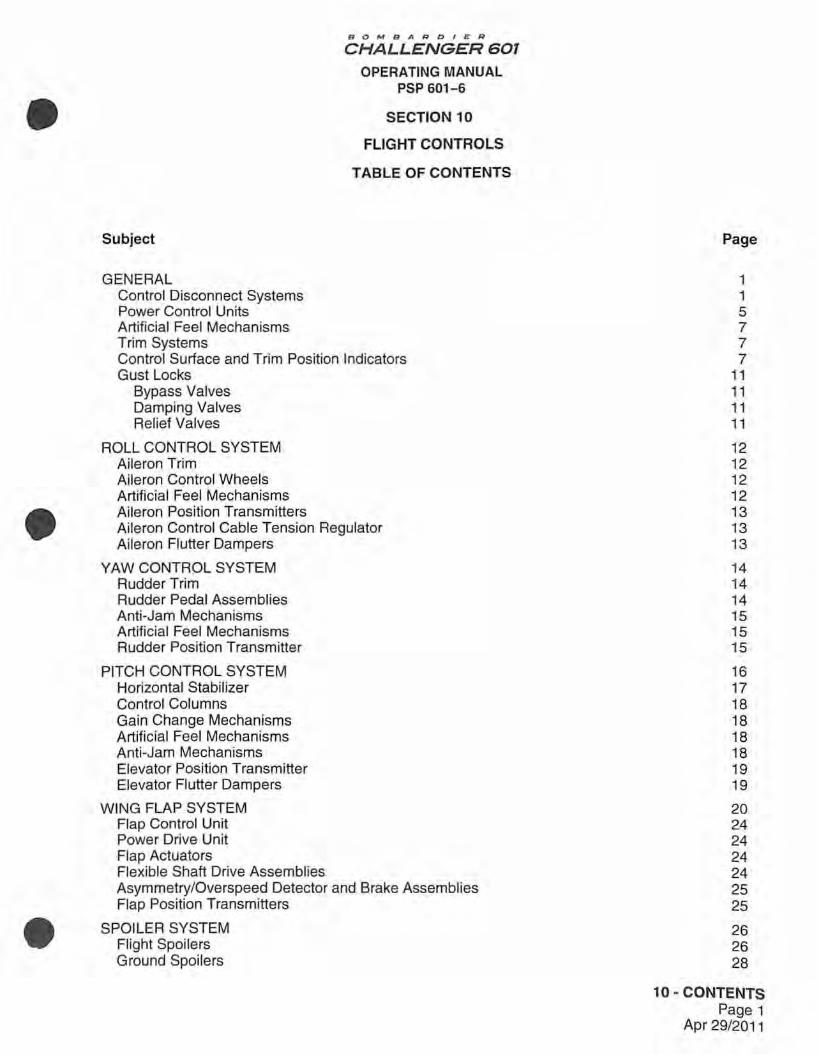
• • • Subject GENERAL Control Disconnect Systems Power Control Units Artificial Feel Mechanisms Trim Systems BOMBA R D I E R CHALLENGER 601 OPERATING MANUAL PSP 601-6 SECTION 10 FLIGHT CONTROLS TABLE OF CONTENTS Control Surface and Tr im Position Indicators Gust Locks Bypass Valves Damping Valves Relief Valves ROLL CONTROL SYSTEM Aileron Trim Aileron Control Wheels Artificial Feel Mechanisms Aileron Position Transmitters Aileron Control Cable Tension Regulator Aileron Flutter Dampers YAW CONTROL SYSTEM Rudder Trim Rudder Pedal Assemblies Anti-Jam Mechanisms Artificial Feel Mechanisms Rudder Position Transmitter PITCH CONTROL SYSTEM Horizontal Stabilizer Control Columns Gain Change Mechanisms Artificial Feel Mechanisms Anti-Jam Mechanisms Elevator Position Transmitter Elevator Flutter Dampers WING FLAP SYSTEM Flap Control Unit Power Drive Unit Flap Actuators Flexible Shaft Drive Assemblies Asymmetry/Overspeed Detector and Brake Assemblies Flap Position Transmitters SPOILER SYSTEM Flight Spoilers Ground Spoilers Page 1 1 5 7 7 7 11 11 11 11 12 12 12 12 13 13 13 14 14 14 15 15 15 16 17 18 18 18 18 19 19 20 24 24 24 24 25 25 26 26 28 1 O - CONTENTS Page 1 Apr 29/2011
Transcript of 12spoiler control spoiler co lever ano splrs r;::!'~~l switches 0 ·warning light flight controls...
•
•
•
Subject
GENERAL Control Disconnect Systems Power Control Units Artificial Feel Mechanisms Trim Systems
BOMBA R D I E R
CHALLENGER 601
OPERATING MANUAL PSP 601-6
SECTION 10
FLIGHT CONTROLS
TABLE OF CONTENTS
Control Surface and Trim Position Indicators Gust Locks
Bypass Valves Damping Valves Relief Valves
ROLL CONTROL SYSTEM Aileron Trim Aileron Control Wheels Artificial Feel Mechanisms Aileron Position Transmitters Aileron Control Cable Tension Regulator Aileron Flutter Dampers
YAW CONTROL SYSTEM Rudder Trim Rudder Pedal Assemblies Anti-Jam Mechanisms Artificial Feel Mechanisms Rudder Position Transmitter
PITCH CONTROL SYSTEM Horizontal Stabilizer Control Columns Gain Change Mechanisms Artificial Feel Mechanisms Anti-Jam Mechanisms Elevator Position Transmitter Elevator Flutter Dampers
WING FLAP SYSTEM Flap Control Unit Power Drive Unit Flap Actuators Flexible Shaft Drive Assemblies Asymmetry/Overspeed Detector and Brake Assemblies Flap Position Transmitters
SPOILER SYSTEM Flight Spoilers Ground Spoilers
Page
1 1 5 7 7 7
11 11 11 11
12 12 12 12 13 13 13
14 14 14 15 15 15
16 17 18 18 18 18 19 19
20 24 24 24 24 25 25
26 26 28
1 O - CONTENTS Page 1
Apr 29/2011

Subject
B 0fv1B A ROIER
CHALLENGER 601
OPERATING MANUAL PSP 601-6
STALL PROTECTION SYSTEM Angle-of-Attack Transducers Stall Protection Computer Stall Protection System Monitoring Stick Shakers Stick Pusher Subsystem Stall Protection System Test Indicators Aural Warning Horn Failure Warning Lights System Test Switches
LIST OF ILLUSTRATIONS
Figure Number Title
1 Flight Controls Hydraulics
2 Flight Controls and Associated Instruments
3 SeNo Monitor Panel
4 Surface Trim Control Panel
5 Control Wheel
6 Control Surface Position and Trim Position Indicators
7 Wing Flap System Components
8 Wing Flap Controls and Indication
9 Spoiler Controls and Indication
10 Stall Protection System Controls and Indications
11 Stall Protection System Indicators
12 Stall Protection System Panels
Page
30 35 36 36 37 37 38 38 38 39
Page
2
3
6
8
9
10
21
23
27
31
32
33
10 - CONTENTS Page 2
Apr 29/2011
•
•
•

•
•
•
1. GENERAL
BOMBARDIER
CHALLENGER 601
OPERATING MANUAL PSP 601-6
SECTION 10
FLIGHT CONTROLS
The primary flight controls, consisting of roll control , yaw control, pitch control, flight spoilers and ground spoilers, are fully powered from the three hydraulic systems. Mechanical inputs from the pilot's controls in the cockpit are conveyed via push-pull rods, quadrants and cables to power control units (PCUs). There is no interconnection between the hydraulic systems, and all PCUs are totally independent of each other. The secondary controls, consisting of the wing trailing edge flaps and control surface trim systems, are electrically controlled and actuated.
The ailerons, elevators and the flight spoilers are each powered by two of the three independent hydraulic systems. The rudder is powered by all three systems and the ground spoilers are powered by No. 1 system only (see Figure 1 ). The primary flight control systems are capable of continued safe operation if jamming or disconnection of a component, loss of normal electrical power and, with the exception of the spoilers, loss of hydraulic systems No. 1 and/or No. 2 occur.
Jamming or disconnection of a component is nullified by incorporation of dual control circuits with anti-jam and/or disconnect mechanisms.
Loss of normal electrical power is overcome by an air-driven generator (ADG), which is capable of supplying emergency electrical power and deploys automatically if normal electrical power is lost.
Loss of hydraulic systems No. 1 and/or No. 2 is catered for by hydraulic system No. 3 which supplies a PCU for each of the primary controls, except the spoilers.
A. Control Disconnect Systems
Control disconnect mechanisms are provided for disconnecting the control columns (pitch control) and the control wheels (roll control) , if a jam occurs in their respective cable runs. The disconnect mechanisms are located under the cockpit floor and are operated by the PITCH DISC and ROLL DISC T-handles on the center pedestal (see Figure 2).
The handles are normally stowed in small recesses in the center pedestal when the disconnect mechanisms are engaged. When either handle is pulled up, its associated mechanism is disengaged. The handle can be secured in the disconnect position by rotating it left or right to engage a detent in the center pedestal. When the PITCH DISC handle is pulled, the pilot has control of the left elevator and the copilot controls the right elevator. When the ROLL DISC handle is pulled, the pilot controls the left aileron and the copilot controls the right aileron. The controls can be reconnected by releasing the handle to the stowed position and aligning the control columns or the wheels, as appropriate.
If a jam occurs in the rudder control circuits, break-out bungees and an anti-jam mechanism isolate the jammed circuit. Yaw control is retained by both pilots .
SECTION 10 Page 1
Apr 29/2011

1. GENERAL (CONT'D)
NO. 1 SYSTEM
AC PUMP ,
BOMBARDIER
CHALLENGER 601
OPERATING MANUAL PSP 601-6
ACC
N0.3SYSTEM
AC PUMP 3A
AC PUMP 3B
NO. 2 SYSTEM
~ ~ • •
@ • • • • • • : "II I I I II I I 11'
~
• • • • ID
• • . : • •
ACC .111111~11111111111111~11~ ACC I?
AILERON LH
ELEVATOR LH
•
AILERON RH
111111111111111111 • • • • • • • • • • 1111111111111111111111
• 1111111111111111111111111111111
• • • •
LEGEND
- NO. 1 HYDRAULIC SYSTEM 11II11 NO. 2 HYDRAULIC SYSTEM ~ NO. 3 HYDRAULIC SYSTEM
GROUND SPOILER RH
TO LANDING GEAR
AND BRAKE SYSTEMS
Flight Controls Hydraulics Figure 1
•
(\J 0 0
a' ~I ~
0 (0
~ u.. Cf)
SECTION 10 Page 2
Apr 29/2011
•
•
•

1. •
•
•
GENERAL (CONT'D)
BO M BA ROI ER
CHALLENGER 601
OPERATING MANUAL PSP 601-6
r;:::==M-,ASTER CAUTION AND INDICATOR LIGHTS
s u R F
a:' / _..... .... L ' R ' ELEVATOR
A~ ,,. cl ... ~ E R
RUDDER
CONTROL SURFACE POSITION INDICATOR
~~~~6'! ISNUDRFACE TRIM ICATOR
PITCH DISCONNECT HANDLE
GROUND SPOIWIS
MASTCR CAlITlON
PRESS TO RESET
r.NiROUN!kl\ ~ll.ER0/
(!] SPOILER CONTROL
SPOILER CO LEVER ANO SPLRS r;::!'~~L SWITCHES
0
·W ARNING LIGHT
Flight Controls and. Associated lnstru Figure 2 ments
MASTER CAUTION
PRESS TO RESET
FLAP SYSTEM WARNING LIGHTS
FLAP POSITION INDICATOR POWER DRIVE UNIT
~PULL& ... ~TURN~
0
SECTION 10 Page 3
Apr 29/201 1
COPILOT' S CONTROL WHEEL
WING LET
AILERON
FLIGHT SPOILER
PILOT'S RUDDER PEDALS
CO?tLOT'S CONTROL CO LUMN
PILOT'S CONTROL WHEEL
PILOT'S CONTROL COLUMN
EFFECTIVITY ~ A/ C 3001 to 3059 .
Canadair SB OOl--0~~~ '%orpo~t ing c?ntrol lever on other ·A/Cr spoiler Figure 9. • refer to

BOMBARD/E:R
CHALLENGER 601
OPERATING MANUAL PSP 601-6
THIS PAGE INTENTIONALLY LEFT BLANK
SECTION 10 Page 4
Apr 29/2011
•
•
•

B OMBAFIDl £ FI
CHALLENGER 601
OPERATING MANUAL PSP 601-6
• 1. GENERAL (CONT'D)
•
•
B. Power Control Units
The primary flight control surfaces are fully power-operated by hydraulic actuators known as power control units (PCUs). To provide for fail safe operation and eliminate fluid interflow between the three aircraft hydraulic systems, each aileron is powered by a dual PCU consisting of two independent actuators, each elevator is powered by two independent PCUs, and the rudder is powered by three independent PCUs.
Although the PCUs of the ailerons, rudder and elevators differ in appearance, the principle of design and operation is similar. Each PCU consists of a control valve operated piston moving in a cylinder. The control valve is operated by a mechanical linkage and directs hydraulic fluid under pressure to one side of the cylinder for actuation, or blocks off pressure from both sides when actuation is complete.
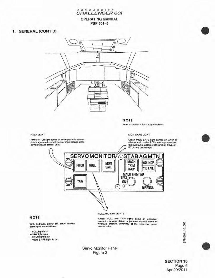
The PCUs are connected to the control surfaces by rod-end attachments and operate to move the control surfaces in the desired direction upon receipt of a signal from the pilot's controls or from the automatic flight control system (AFCS). A flight control monitoring unit, located in the underfloor avionics bay, together with proximity sensors associated with each PCU, monitors the operation of the PCUs. The flight control monitoring unit receives inputs from the proximity sensors and transmits warning signals, via the master caution and warning system, to the SERVO MONITOR panel in the cockpit (see Figure 3). Each proximity sensor forms part of a solid state electrical circuit that produces voltage variations when a metal target moves within a predetermined distance of the sensor. The sensors perform the function of conventional microswitches, but do not requ ire electrical contacts.
The proximity sensors of the roll and yaw control systems are integral parts of their associated PCUs and are capable of detecting a PCU malfunction caused by a jammed PCU control valve or a hydraulic supply deficiency. The pitch control proximity sensors are mounted on the input linkages of their associated PCUs and detect only PCU malfunctions caused by a jammed PCU control valve .
SECTION 10 Page 5
Apr 29/2011
1. GENERAL (CONT'D)
PITCH LIGHT
B0"1BARDl£R
CHALLENGER 601
OPERATING MANUAL PSP 601-6
NOTE Reier to section 4 for "Stabagmtn panel.
MON SAFE LIGHT
Amber PITCH light comes on when proximity sensors dete<:t a jammed conuol valve or input linkage at the elev.nor power control units.
Green MON SAFE light comes on when all aileron and rudder PCUs are unpressuri2ed {all hydraulic systems off} and all elevator PCUs are unjammed.
NOTE
With hydrau~c power off. servo monitor panel lightS are as fellows:
-RDU. light is on -YAW&ghtison -PrTCH light is out
- MON SAFE light is on.
©§TABAG MTN MACH TRIM INOP YID FAIL
MACH TRIM YID
~~o o 8 OFF DISENGA
ROU AND YAW LIGHTS
Amber ROLL and YAW lights come on whenever proximity sensors detect a jammed control valve or hydraulic pressure deficiency at the respective power control units.
Servo Monitor Panel Figure 3
SECTION 10 Page 6
Apr 29/2011
•
•
•
BOMBARDIER
CHALLENGER 601 OPERATING MANUAL
PSP 601-6
• 1. GENERAL (CONT'D)
•
•
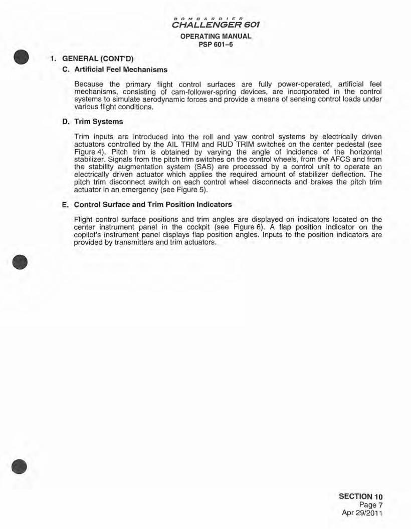
C. Artificial Feel Mechanisms
Because the primary flight control surfaces are fully power-operated, artificial feel mechanisms, consisting of cam-follower-spring devices, are incorporated in the control systems to simulate aerodynamic forces and provide a means of sensing control loads under various flight conditions.
D. Trim Systems
Trim inputs are introduced into the roll and yaw control systems by electrically driven actuators controlled by the AIL TRIM and RUD TRIM switches on the center pedestal (see Figure 4). Pitch trim is obtained by varying the angle of incidence of the horizontal stabilizer. Signals from the pitch trim switches on the control wheels, from the AFCS and from the stability augmentation system (SAS) are processed by a control unit to operate an electrically driven actuator which applies the required amount of stabilizer deflection. The pitch trim disconnect switch on each control wheel disconnects and brakes the pitch trim actuator in an emergency (see Figure 5).
E. Control Surface and Trim Position Indicators
Flight control surface positions and trim angles are displayed on indicators located on the center instrument panel in the cockpit (see Figure 6). A flap position indicator on the copilot's instrument panel displays flap position angles. Inputs to the position indicators are provided by transmitters and trim actuators .
SECTION 10 Page 7
Apr 29/2011

1. GENERAL (CONT'D)
RUDDER TRIM CONTROL
B O M B A RDI E R
CHALLENGER 601
OPERATING MANUAL PSP 601-6
Control switch setS rudder trim left and right.
OVERSPEED/CHANNEL CHANGE SWITCH/LIGHT
Amber lights indicate pitch trim overspeed or channel change. Can be used to change !Tom one channel to ott\er for rest.
Pressing switch/ light in conjunction with CHAN 1/ CHAN 2 switch/Ught activates pitch trim system.
RUD TRIM
L Ci) R
OFF ¢
PITCP~s~RIM @®AIL TRIM CHAN 1 OVSP I
INOP l R CHAN 2 CHANG I
INOP CHAN
CHANNEL INOPERATIVE SWITCH/LIGHT
CHAN 1 INOP
OFF =======
AILERON TRIM CONTROLS CHAN 2 INOP
Amber lights ndicate failure in respective channel.
Pressing switch/ light in conjunC1ion with OVS P / CHANGE CHAN switch/light activates pitch trim system.
Control SWitches sets aileron trim up and down.
Surface Trim Control Panel Figure 4
SECTION 10 Page 8
Apr 29/2011
•
•
•
•
•
•
BOMBAl'?OIEI'?
CHALLENGER 601 OPERATING MANUAL
PSP 601-6
1. GENERAL (CONT'D)
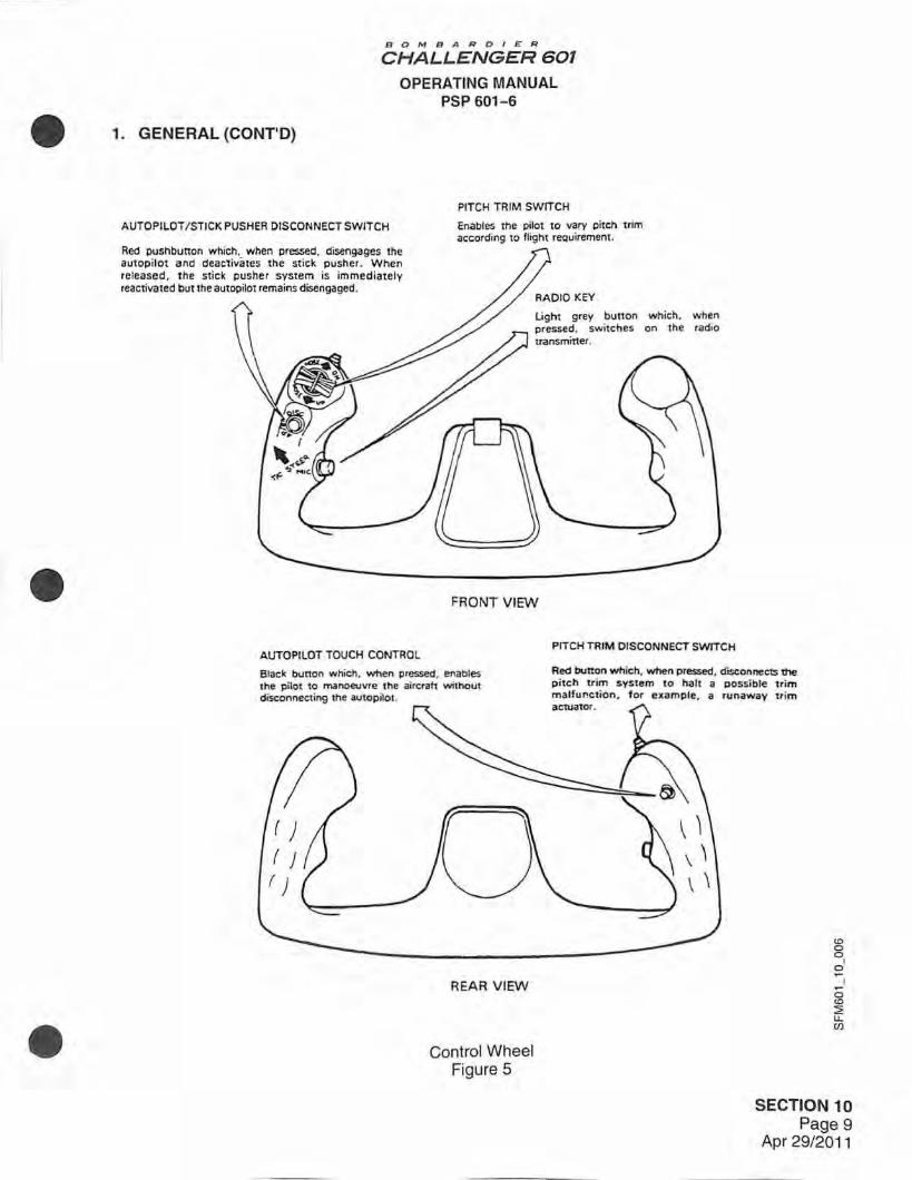
AUTOPILOT / STICK PUSHER DISCONNECT SWITCH
Red pushbunon which, when pressed. disengages the autopilot and deactivates the stick pusher . When released. the stick pusher system is immediately reactivated but the autopilot remains disengaged.
AUTOPILOT TOUCH CONTROL
PITCH TRIM SWITCH
Enables the pilot to vary pitch trim according to flight reQuirement.
light grey button which. when pressed. switches on the radio
FRONT VIEW
PITCH TRIM DISCONNECT SWITCH
Black bunon which. when pressed, enables the pilot to manoeuvre the aircraft without disconnect ing the autopilot .
Red button which, when pressed, disconnects the pitch t rim system to halt a possible trim malfur.ction. for example, a runaway trim
REAR VIEW
Control Wheel Figure 5
SECTION 10 Page 9
Apr 29/2011

BO MB ARDIE:R
CHALLENGER 601
OPERATING MANUAL PSP 601-6
1. GENERAL (CONT'D)
LANDR FLTSPLR
LAND R ELEVATOR
Up/down indications
Up 23.6 degrees Down 18.4 degrees
AIL LWO AND RWD
Wing up/ down indications
Up 7 .5 degrees Down 7 .5 degrees
CONTROL S URFACE POSITION INDICATOR
0
CONTROL SURFACE TRIM POSITION INDICATOR
STABNUP
LAND R AILERON
Wing up/ down indiC<1tions
Up 21.3 degrees Down 21.J degrees
RUDDER
LefVright indications
LEFT 25 degrees RIGHT 25 degrees
Nose up INUP) indications
Stabilizer moves from Oto -9 degrees incidence. Green band indicates take-off !TOI trim range.
NOTE If input signals to trim indicato< are lost. aileron and rudder pointers move off scale 90 degrees from zero index. StabJczer pointl!f moves otf scale to a point between scale end poims.
l{)
0 0 1 0 ~I ~
0 <O :2 u. (/)
Control Surface Position and Trim Position Indicators Figure 6
SECTION 10 Page 10
Apr 29/2011
•
•
•

BOMBARDIER
CHALLENGER 601
OPERATING MANUAL PSP 601-6
• 1. GENERAL (CONT'D)
•
•
F. Gust Locks
To provide gust locking fo r the ailerons and the rudder, a bypass valve is included in each of the rudder PCUs, and a damping valve is included in each of the aileron PCUs. The valves are similar in construction and actuation, but operation of the damping valves differs slightly from that of the bypass valves. Gust locking for the elevators is provided by relief valves on the elevator PCUs.
(1) Bypass Valves
When hydraulic pressure is removed from the PCU, spring force moves the valve spool to the bypass position at which the extend and retract ports of the PCU are interconnected through a restrictor orifice in the bypass valve. At the same time, the retract port of the PCU control valve is blocked. These two actions lock the control surface against the effect of gusts but permit restricted movement of the surface, if a sufficiently large external force is applied continuously.
When hydraulic pressure is restored, the valve spool moves back to the non-bypass position. In this position, the retract port of the PCU is connected to the PCU cylinder and normal operation of the control surface is possible.
(2) Damping Valves
When hydraulic pressure is removed, spring force moves the valve to the damping position. With the valve in this position, the extend port of the PCU cylinder is connected through a restrictor port in the damping valve to the pressure port of the PCU control valve which is open to the retract port of the PCU cyl inder. When the PCU is in this configuration, the aileron is gust locked, but is capable of restricted movement when a steady external force is applied to it.
When hydraulic pressure is applied, the pressure overcomes the spring force and moves the valve spool to the non-damping position. In the non-damping position, the damping valve connects the extend port of the PCU cylinder to the return port of the PCU control valve and connects the pressure line to the pressure port of the PCU control valve, rendering the PCU operative.
(3) Relief Valves
The pressure relief valve on each elevator PCU connects the PCU cylinder extend and retract pressure lines. When hydraulic pressure is removed, a spring forces the valve closed. This action gust locks the elevator but allows restricted movement of the surface if a steady external force is applied to it.
When hydraulic pressure is applied, the relief valve opens and connects the PCU cylinder extend and retract pressure lines to restore normal operation of the elevator .
SECTION 10 Page 11
Apr 29/2011

2. ROLL CONTROL SYSTEM
BOMBARO/£R
CHALLENGER 601
OPERATING MANUAL PSP 601-6
Roll (lateral) control is achieved by hydraulically powered ailerons which are controlled primarily from conventional column-mounted, horn-type wheels through a system of pulleys, cables, quadrants, push-pull rods, levers and bellcranks. Aileron movement is limited by the operating range of the hydraulically actuated PCUs to which the ailerons are connected, and by mechanical stops on the pilot's and copilot's control wheels. Primary control is supplemented by an electrically actuated trim system.
The roll control system incorporates a dual PCU for each aileron, and a dual control system. Normally both control systems are interconnected by a cross-coupling shaft so that there is simultaneous movement of both ailerons. However, it is possible to isolate a jammed aileron control circuit by means of a disconnect mechanism, thereby allowing limited control (one aileron only) through the unjammed circuit (refer to Control Disconnect Systems).
Control wheel movement is transmitted by a cable to a pulley located at the base of each control column, then horizontally rearward under the cockpit floor where each of the twin cable circuits drives one of the two forward quadrants which form a transverse cross-coupling shaft. From the forward quadrants, control cables are routed under the cabin floor to rear quadrants, located in the main landing gear bay, each of which incorporates an artificial feel unit. Output from each rear quadrant is transmitted outboard, by cable, to a PCU input quadrant located outboard in the wing, forward of the rear spar. Each input quadrant has a cable tension regulator and is connected to the input/feedback linkages of the dual PCU through a common linkage.
The actuator pistons are connected to the ailerons by jointed toggles, and each actuator is capable of aileron operation should there be a failure associated with the adjacent actuator.
•
Movement of the PCU input/feedback linkage causes movement of the PCU control valve which, in turn, actuates the PCU piston to move the aileron according to the control command. Piston • movement also repositions the input/feedback linkage to return the PCU control valve to a neutral position, thus preventing further movement of the ailerons until a subsequent control signal moves the PCU input/feedback linkage. Signal inputs from the AFCS are made through the rear quadrant of the right aileron system only. Therefore, should jamming of the right control system occur, the autopilot inputs would not be transmitted to the left aileron system, (refer to Section 4, AUTOMATIC FLIGHT CONTROL SYSTEM).
A. Aileron Trim
An electrically driven actuator, located in the main landing gear bay between the rear quadrants, applies a bias to the primary control circuit, when required, by operation of the AIL TRIM switches located on the center pedestal. The trim actuator is connected to the rear quadrants via push-pull rods and bellcranks. The amount of trim applied to the ailerons is shown on the control surface trim position indicator, located on the left of the center instrument panel.
B. Aileron Control Wheels
The aileron control wheels are horn-type handwheels, spline-mounted on the control columns (see Figure 5). The wheels are connected by cables to the aileron forward quadrants via pulleys located near the base of the control columns. Each control wheel mounts a pitch trim switch, a pitch trim disconnect switch, an autopilot/stick pusher disconnect switch, an autopilot touch control switch and a radio key.
C. Artificial Feel Mechanisms
Two artificial feel mechanisms, one at the rear of each rear quadrant, provide the pilot's with • positive feel of the power-operated control system and act as centering devices.
SECTION 10 Page 12
Apr 29/2011

BOMBAROll:R
CHALLENGER 601
OPERATING MANUAL PSP 601-6
• 2. ROLL CONTROL SYSTEM (CONT'D)
•
•
D. Aileron Position Transmitters
A position transmitter connected to each aileron transmits aileron position signals to the control surface position indicator on the center instrument panel (see Figure 6). An additional aileron position transmitter, connected to the left aileron, signals aileron position to the stability augmentation computer of the automatic fl ight control system. The aileron position signals are used to enhance yaw damping during rolling manoeuvres.
E. Aileron Control Cable Tension Regulator
The aileron PCU input quadrant incorporates a cable tension regulator. The tension regulator maintains optimum control cable tension by compensating for changes in tension caused by temperature variations, stretching of the control cables and deflection of the control system components.
F. Aileron Flutter Dampers
Each aileron is protected by a single hydraulic flutter damper assembly. The flutter damper consists of a pre-charged hydraulic cylinder containing a double-acting piston. The piston rod is connected via a shear link to the aileron at the outboard aileron hinge assembly. Flutter damping occurs when hydraulic fluid is forced from one side of the piston to the other through small diameter passages. The hydraulic fluid level in the damper can be checked through an integral sight gauge .
SECTION 10 Page 13
Apr 29/2011

3. YAW CONTROL SYSTEM
BOMB A RDI E R
CHALLENGER 601
OPERATING MANUAL PSP 601-6
Yaw (directional) control is achieved by a hydraulically powered rudder, controlled primarily from conventional dual, cross-coupled pedals through a system of push-pull rods, levers, quadrants, cables, pulleys and bellcranks. Rudder movement is limited by the operating range of the hydraulically actuated rudder PCUs, and by mechanical stops which limit the movement of the control pedals. Primary control is supplemented by an electrically actuated trim system.
The yaw control system incorporates three independent, parallel-connected PCUs and a dual control system which includes two anti-jamming mechanisms for isolating or overriding the effects of a jammed circuit, enabling control to be maintained via the intact circuit. The system is also protected by anti-jam mechanisms built into the PCU input levers, which act to isolate a jammed PCU.
Movement of the pedal assembly is transmitted to forward quadrants by a push-pull rod and lever system which includes a primary feel mechanism and forward anti-jam mechanism. From each forward quadrant, the control signal is transmitted by cables, along each side of the fuselage, under the cabin floor, to a corresponding rear quadrant in the rear fuselage. The two rear quadrants, located centrally side by side, convey the dual control signal onwards as a single signal, via a secondary feel mechanism, a rear anti-jam mechanism, two load limiters and a trim mixing system, to the input torque tube of the PCUs. The PCU input torque tube incorporates one input and three identical output levers. Each output lever is connected to the input/feedback linkage, which transmits the control signal to the control valve of the PCU. Operation of the rudder PCUs is similar to that of the aileron PCUs (refer to Roll Control System).
In addition to control inputs from the pedal assembly, inputs from the stability augmentation system of the AFCS are applied to the system through two yaw dampers in the trim mixing system (refer to Section 4, AUTOMATIC FLIGHT CONTROL SYSTEM).
A. Rudder Trim
An electrically driven actuator, connected to the rudder PCUs via the trim mixing system, applies a bias· to the primary control circuit, when required, by operation of the RUD TRIM control located on the center pedestal. The amount of trim applied to the rudder is shown on the control surface trim indicator located on the left of the center instrument panel.
B. Rudder Pedal Assemblies
Each rudder pedal is pivot-mounted on its own tubular pedestal which, in turn, is pivot-mounted to lugs on a cross-mounted tube secured to the structure below the cockpit floor. The pedals are pivot-mounted to enable foot control of the aircraft wheel brake system via control rods, levers and cables. The tubular pedestals are pivot-mounted to convey the pilot's foot movement to the rudder control system.
Each set of pedals is provided with a hand-operated adjusting mechanism to cater for the individual requirements of the pilots. The right hand set of pedals incorporates the primary artificial feel mechanism which consists of a simple cam-follower-spring device.
SECTION 10 Page 14
Apr 29/2011
•
•
•

BOMB A RDIER
CHALLENGER 601
OPERATING MANUAL PSP 601-6
• 3. YAW CONTROL SYSTEM {CONT'D)
•
•
C. Anti-Jam Mechanisms
The two forward anti-jam mechanisms, one located adjacent to each forward quadrant under the cockpit floor, and one rear anti-jam mechanism, located adjacent to the rear quadrants in the rear fuselage, operate to nullify the effects of a jammed cable circuit. Normally, with both cable circuits unrestricted, the rear anti-jam mechanism acts as a summing device so that movement of the rear quadrants, though in opposite directions, is summed to produce twice the output movement of one quadrant. If one rear quadrant cannot move because of a jammed condition in the cable circuit, the forward anti-jam mechanisms alter the pivot points of the forward quadrants to produce twice the normal movement of one rear quadrant and thereby maintain normal pedal/ rudder movement ratio.
The anti-jam mechanism on each rudder PCU acts as a push/pull rod for the PCU input linkage during normal operation. If the input linkage cannot move because of a jam in the PCU, the anti-jam mechanism breaks out to isolate the defective PCU from the system. The remaining PCUs continue to operate the rudder.
D. Artificial Feel Mechanisms
Two artificial feel mechanisms are included in the yaw control system. A primary mechanism, incorporated into the copilot's pedal assembly, provides both pilots with positive feel of the power-operated system and acts as a centering device for the system. A secondary mechanism, included in the rear linkage, caters for control system backlash in addition to providing feel and acting as a centering device.
E. Rudder Position Transmitter
A position transmitter, located at the bottom rudder hinge, transmits rudder position signals continuously, over the full range of travel , to the control surface position indicator on the left of the center instrument panel.
SECTION 10 Page 15
Apr 29/2011

4. PITCH CONTROL SYSTEM
BOMBARDIER
CHALLENGER 601
OPERATING MANUAL PSP 601-6
Pitch (longitudinal) control is achieved primarily by two independent, hydraulically powered elevators which are hinge-mounted to the trailing edge of the horizontal stabilizer. Elevator movement is controlled from conventional control columns through a dual system of pulleys, cables, quadrants, push-pull rods, levers and bellcranks. Elevator movement is limited by the operating range of the hydraulically actuated PCUs and by mechanical stops which limit the movement of the control columns. Primary control is supplemented by an electrically actuated trim system which varies the angle of incidence of the horizontal stabilizer, and is operated via a trim control unit, from switches mounted on the pilot's and copilot's control wheels.
The pitch control system incorporates two parallel-connected PCUs for each elevator, and a dual control system. Normally, both control systems are interconnected via the control column transverse coupling shaft so that there is simultaneous movement of both elevators. However, it is possible to isolate a jammed circuit by means of a disconnect mechanism, thereby providing limited pitch control (one elevator only) through the remaining circuit (refer to Control Disconnect System). Anti-jam mechanisms are included in each of the PCU input rod linkages.
Control column movement is transmitted to forward quadrants by push-pull rods. From each forward quadrant, control signals are conveyed by cables along each side of the fuselage below the cabin floor to the respective rear quadrant mounted on the rear face of the vertical stabilizer forward spar. Output from each rear quadrant is transmitted by push-pull rods, to a gain change mechanism and to an artificial feel unit.
From the gain change mechanism, the control signal is transmitted to the PCU input tube via a load limiter, bellcranks and push-pull rods. The PCU input tube incorporates one input and two identical output levers, and each of the output levers is connected to the input/feedback linkage of the PCU, transmitting the control signal to the control valve of the PCU. Operation of the elevator PCUs is similar to that of the aileron PCUs (refer to Roll Control System).
Signal inputs from the AFCS are made through the rear quadrant of the left elevator control system only. Therefore, should jamming of the left cable circuit occur, the autopilot inputs would no longer be available to the elevator system.
SECTION 10 Page 16
Apr 29/2011
•
•
•
BOMBARD/£R
CHALLENGER 601
OPERATING MANUAL PSP 601-6
• 4. PITCH CONTROL SYSTEM (CONT'D)
•
•
A. Horizontal Stabilizer
The aircraft is trimmed in pitch by varying the horizontal stabilizer angle of incidence. Trim commands from the pilot's or copilot's control wheel switches, the AFCS and the SAS, processed by a trim control unit, operate the electrically driven stabilizer actuator. In order to enhance the longitudinal trim movement, the movement of the horizontal stabilizer is accompanied throughout its range of operation by a degree of elevator movement that alters the stabilizer/elevator camber. The geometry is such that an elevator servo input is generated as the horizontal stabilizer is moved, the servo input being sufficient to produce the required elevator deflection.
The electrically driven screw actuator, located at the top of the vertical stabilizer, varies the horizontal stabilizer angle of incidence. The actuator is driven by two electric motors, directly connected to the drive train, each containing a high and a low speed winding. Manual trim commands from the pitch trim switches on the control wheels produce a steady rate of stabilizer movement of one-half degree per second. Depending on flap position, the autopilot commands variable high or low trim rates of 0.1 to 0.5 degrees per second and 0.01 to 0.1 degrees per second respectively. Mach trim commands produce a variable rate of stabilizer movement between 0.01 and 0.1 degrees per second. Each of the electric motors driving the trim actuator is protected against overspeed by a dual coil brake.
The control unit, located in the avionics bay, controls the rate and direction of movement of the actuator. The unit consists of two independent channels and operates from two power busses so that electrical failure on one bus does not preclude operation of the stabilizer trim. A pilot reset capability allows channel transfer at the pilot's discretion .
The system normally operates on channel No. 1, with channel No. 2 performing only a monitoring function. Should a failure occur within a controller channel or its associated motor, the control unit automatically signals that the channel is inoperative and transfers to the backup channel. In the event of an overspeed condition, the control unit removes power from the drive motor, operates the brake in the actuator and provides a shutdown signal to the pilot.
Two trim position sensors on the actuator send signals to the control unit. One sensor supplies the AFCS with stabilizer angle data and the second is connected to the flight recorder. Both position sensors provide travel limit signals for the control unit. Stabilizer trim position is also an input to the take-off configuration warning system. A third position sensor, located on the stabilizer rear spar, supplies position signals to the control surface trim position indicator on the center instrument panel.
A panel mounted on the center pedestal has two ganged amber switch/lights, CHAN 1 INOP and CHAN 2 INOP, that indicate failures in their respective pitch trim control unit channel (refer to Figure 4). Normally, channel No. 1 is engaged and both switch/lights are out. A combined overspeed/channel change switch/light, OVSP CHANGE CHAN, is also located on the panel. For test purposes, this switch/ light can be used to change the system from one channel to the other.
Pitch trim is activated by first pressing the CHAN 1 INOP/CHAN 2 INOP switch/lights and then the OVSP CHANGE CHAN switch/light on the center pedestal control panel. Commands from the pilot's trim switch override those from the copilot's trim switch, the AFCS and the SAS. Commands from the copilot's trim switch override only those from the AFCS and the SAS.
The pilot's control wheels each have a red disconnect button, PITCH TRIM DISC, which can be pressed to remove power from the system and brake the actuator (refer to Figure 5). Re-engagement of the trim system is accomplished by again pressing the CHAN 1 !NOP/CHAN 2 !NOP switch/light and then the OVSP CHANGE CHAN switch/light.
SECTION 10 Page 17
Apr 29/2011

BOMBAROleR
CHALLENGER 601
OPERATING MANUAL PSP 601-6
4. PITCH CONTROL SYSTEM (CONT'D)
B. Control Columns
The pilot's and copilot's control columns each consist of a conventional tubular column, mounted vertically in a housing. A push-pull rod connected at the rear of the column base transmits column movement to the pitch control system. A control column shaker, which is a component part of the stall protection system, is mounted on the column .
C. Gain Change Mechanisms
The two independent gain change mechanisms consist of bell cranks and push-pull rods. The mechanisms are located side by side in the vertical stabilizer, between the rear quadrants and the PCU input linkages, and are identical in form and function.
The purpose of the gain change mechanisms is to convert the rotational input from the rear quadrants into linear output in such a way as to ensure that the rate of elevator movement increases as the control column is moved from neutral to provide the required control response.
D. Artificial Feel Mechanisms
Two artificial feel mechanisms, one for each elevator, provide the pilots with positive feel of the power-operated systems and act as centering devices for the systems. Each unit consists of a main feel cam and follower, a primary spring box and a secondary spring box.
•
The primary and secondary spring boxes load the feel mechanism cam followers, and feel rate is achieved by movement of the cam follower along the cam profile. The load exerted by the primary spring box depends on the position (angle of incidence) of the horizontal stabilizer • which varies according to manual or automatic trim commands. The secondary spring box is designed so that its contribution to feel force is released when the control column input exceeds a predetermined load, ensuring a reduced feel force when rapid control column movement is required.
E. Anti-Jam Mechanisms
The elevator anti-jam mechanisms act normally as push/pull rods for the PCU input rod linkages. If a PCU input linkage cannot move because of a jam in the PCU, the mechanism breaks out to isolate the defective PCU from the system. The other PCU continues to operate the affected elevator.
When the mechanism breaks out, a proximity sensor is deactivated and the amber PITCH light on the SERVO MONITOR panel comes on (refer to Figure 3).
SECTION 10 Page 18
Apr 29/2011
•

BOMBARDIE:R
CHALLENGER 601
OPERATING MANUAL PSP 601-6
• 4. PITCH CONTROL SYSTEM (CONT'D)
•
•
F. Elevator Position Transmitter
A position transmitter, located on the rear spar of the horizontal stabilizer, transmits elevator position signals continuously, over the full range of travel , to the control surface position indicator on the left of the center instrument panel.
G. Elevator Flutter Dampers
Each elevator is protected against aerodynamic flutter by two flutter damper assemblies. Each damper consists of a pre-charged hydraulic cylinder containing a double-acting piston. Flutter damping occurs when loads are placed on the piston rod, forcing hydraulic fluid from one side of the piston to the other through small diameter passages. The dampers connect with the elevator immediately outboard and inboard of the elevator center hinge. The hydraulic fluid level in each damper can be checked through an integral sight gauge .
SECTION 10 Page 19
Apr 29/2011
5. WING FLAP SYSTEM
B OMB A RDI ER
CHALLENGER 601
OPERATING MANUAL PSP 601-6
The wing flap system consists of externally hinged, inboard and outboard double-slotted flap panels mounted on the trailing edge of each wing. The panels are electrically driven by a power drive unit (POU) located in the main landing gear bay. The motor action of the POU is translated to eight actuators, two to each flap panel, by flexible shaft assemblies. An asymmetry/overspeed detector and brake unit is incorporated in each flap drive system (see Figure 7).
The outboard flaps have fixed leading edge vanes and the inboard flaps have moveable leading edge vanes which automatically extend or retract as the flaps are lowered or raised. Each of the three hinges of the outboard flaps incorporates a spring actuator which is connected by a rod to a bent up trailing edge (BUTE) door, hinged on the lower surface of the wing. Rollers on the BUTE doors are kept in contact with cam-shaped fittings attached to the vane and, as the flaps are lowered or raised, the movement of the BUTE doors is governed by the cam profile. When the flaps are fully down, the BUTE doors take up a raised position to direct airflow over the vane and flap assemblies.
The flaps are extended or retracted in response to command signals from the FLAPS control lever located on the center pedestal. Flap position is set by the feel detents on the flap control lever quadrant. Four positions are provided corresponding to the following operating modes:
Flight/taxiing
Take-off
Approach
Landing
O degrees
20 degrees
30 degrees
45 degrees
•
The signals are fed to the POU via the flap control unit. If the control unit logic detects an • anomaly, such as flap asymmetry or overspeed, power is removed, causing the POU motor brakes and the asymmetry/overspeed detector brakes to stop the system. When a system fault is detected, a signal is transmitted to the warning system and the amber FLAPS FAIL light comes on above the flap position indicator located on the copilot's instrument panel (see Figure 8).
SECTION 10 Page 20
Apr 29/2011
•

•
•
•
5. WING FLAP SYSTEM (CONT'D)
FLAP CONTROL LEVER
B0 "'1 B A ROIER
CHALLENGER 601 OPERATING MANUAL
PSP 601-6
F LAP LEVER QUADRANT
FLAP LEADING EDGE VANE (INBOARD)
VANE ACTUATING MECHANISM
Wing Flap System Components Figure 7
0 FLAP ACTUATOR AND HINGE
SECTION 10 Page 21
Apr 29/2011
FLAP CONTROL UNIT
ASYMMET RY/OVERSPEED e DETECTOR AND BRAKE UNIT
co 0
~I ~I
0 <D ~ u... en

BO MBARDI ER
CHALLENGER 601
OPERATING MANUAL PSP 601-6
THIS PAGE INTENTIONALLY LEFT BLANK
SECTION 10 Page 22
Apr 29/2011
•
•
•

•
•
•
5. WING FLAP SYSTEM (CONT'D)
FLAP CONTROL LEVEL
Lever is guarded to itS full height to obviate inadvertent operation.
Lever quadrant is marked with the four f light modes:
Flight/Taxiing Take.off Approach Landing
0de9rees 20degrees JO degrees 45de9rees
each mode corresponding with a detented position of the lever.
B0"'1BAROIE:R
CHALLENGER 601
OPERATING MANUAL PSP 601-6
FLAP FAIL LIGHT
POU MOTOR OVERHEAT LIGHTS
Amber light comes on 10 indicate an overheat condition in the associated POU motor.
Amber light comes on to indicate a asymmetry or speed response fault .
flap
''::;: OVHT MOT l OVHT
MOT 2
FLAP POSITION INDICATOR
Provides a continuous angular indication of the flaps over their operating range.
Wing Flap Controls and Indication Figure 8
SECTION 10 Page 23
Apr 29/2011

5. WING FLAP SYSTEM (CONT'D)
A. Flap Control Unit
BO,,.,fBARDIER
CHALLENGER 601
OPERATING MANUAL PSP 601-6
The flap control unit (FCU) is located in the underfloor avionics bay and is powered from DC bus No. 1 and DC bus No. 2. Although two power supplies are provided, only one is necessary to operate the unit. The function of the unit is to assess the flap extend/retract commands received from the FLAPS control lever and provide the correct activating signal to the POU. Once a selected flap angle is reached, the flaps are locked in position by the POU motor brakes and the asymmetry/overspeed detector brake units.
The FCU also signals the aural warning unit (refer to Section 3, AURAUVISUAL WARNING SYSTEMS) to initiate the following aural warnings:
• A wailer, when the airspeed is too great for the flap position selected • An intermittent horn, when the take-off configuration is incorrect (aircraft on ground, either
throttle lever set beyond IDLE and flaps set to any position other than 20 degrees)
• A horn, when flaps are set to more than 30 degrees with the landing gear up.
8. Power Drive Unit
The POU, located in the main landing gear bay at the aircraft centerline, has a dual output shaft which is coupled to the left and right side flap flexible drives. The two POU motors are coupled to a mechanical differential which drives the output shaft through a clutch and an output gear train. With power applied to the POU , the motor brakes are released and the motor shafts rotate to drive the internal gear train to provide driving torque for the flexible shaft assemblies and actuators. When the selected flap position is reached, the FCU
•
responds to a POU potentiometer signal and opens a relay to de-energize the motors and • apply the motor brakes.
If power to one of the POU motors fails, the associated brake is automatically applied, locking the POU input to the differential and the second motor continues to operate the system at half speed. In the event of overheating of a POU motor, thermal switches de-energize the applicable motor and an amber overheat light, OVHT MOT 1 or OVHT MOT 2, comes on above the flap position indicator. The thermal switches reset once the overheat condition has passed.
C. Flap Actuators
Eight flap actuators are located on the flap hinge attachment fittings, two actuators to each flap . The actuators are of the linear mechanical type and consist of a housing assembly, worm and helical gears and a ball screw assembly with a ball nut extension tube. Adapters for attachment of the flexible shafts are provided. The flap is connected to a gimbal block attached to the ball nut. Two different gear reductions are used to achieve a uniform movement of both flaps with respect to the swept wing configuration.
D. Flexible Shaft Drive Assemblies
The flap drives, one to each wing, are located along the rear and auxiliary spars in the wing trailing edge. The drives are in the form of two flexible shafts, each made up of five segments connected from the POU to the four actuators and to the asymmetry/overspeed detector and brake assembly in each wing.
SECTION 10 Page 24
Apr 29/2011
•
BOMBARDIER
CHALLENGER 601 OPERATING MANUAL
PSP 601-6
• 5. WING FLAP SYSTEM (CONT'D)
•
•
E. Asymmetry/Overspeed Detector and Brake Assemblies
These components are located adjacent to the rear spar, between the outboard flap and aileron of each wing and are coupled by a segment of the flexible shafts to the outboard actuators. The function of these assemblies is to transmit signals to the FCU to provide positive braking action to the flaps in the event of asymmetric movement of the left and right flaps, or overspeed.
F. Flap Position Transmitters
Two flap position transmitters are provided, one each on the left and right inboard flap assemblies at the respective inboard hinge boxes. Both transmitters send flap position signals to the stall protection system computer (refer to Stall Protection Computer). -
A flap position potentiometer is contained in the right flap position transmitter only. The potentiometer transmits flap position signals to the flap position indicator on the copilot's instrument panel (refer to Figure 8) .
SECTION 10 Page 25
Apr 29/2011

6. SPOILER SYSTEM
BOMBARDIE:R
CHALLENGER 601
OPERATING MANUAL PSP 601-6
Wing lift modulation is achieved by the operation of flight and ground spoilers (see Figure 9). The flight spoilers may be extended to any position, between O and MAX (40 degrees), as required for the intended flight path. The ground spoilers have only two positions, fully retracted during flight or fully deployed (45 degrees) when the aircraft is on the ground, to assist other braking systems by dumping lift and increasing drag.
A. Flight Spoilers
The flight spoilers are two hydraulically powered panels, one hinged to each wing trailing edge upper surface, in the area of the outboard flaps, and are controlled mechanically through pilot movement of a lever on the center pedestal. Each panel is powered by two hydraulically independent PCUs secured to the wing auxiliary spar. Each PCU is independently connected to its spoiler and is capable of spoiler operation should the adjacent PCU fail either mechanically or hydraulically.
The spoiler control lever is connected to the PCUs via a push-pull rod, pulley, cable and lever system. The spoilers are fully retracted when the lever is in the fully forward position. This provides natural control, similar to throttle lever movement, in that rearward movement of the spoiler control lever deploys the flight spoilers and slows the aircraft.
Lever positions, when selected, are held by a serrated plate and plunger mechanism. The lever is gated at the fully deployed position to prevent inadvertent movement into the ground spoiler arming area.
A position transmitter, located inboard of the PCUs of each flight spoiler, transmits position
•
signals to the control surface position indicator on the center instrument panel. A proximity • sensor switch, located between the PCUs at each spoiler, senses spoiler position (retracted or extended) and transmits a signal to the amber LH FLT SPLR and RH FLT SPLR lights on the glareshield which come on when the spoilers are not in the fully retracted position. The LH FLT SPLR and RH FLT SPLR lights come on flashing and the take-off configuration aural warning horn sounds if the flight spoilers are deployed and either engine is operating at an N1 rpm above 75%.
A detent mechanism on both of the spoiler wing circuits prevents unacceptable spoiler asymmetry if a controlex cable disconnects. If a cable disconnect occurs, the detent mechanism closes the affected spoiler when the spoilers are less than one-half extended or retracts it to the one-half extended position when the spoilers are more than one-half extended.
Microswitches on each detent mechanism cause the LEFT and RIGHT FLIGHT SPOILERS lights on the center pedestal to come on when the flight spoilers are more than one-half extended. Operation of the lights indicates that the flight spoiler detent mechanism is serviceable and that blowback protection in an asymmetrical spoiler condition has been reset to the one-half extended position.
SECTION 10 Page 26
Apr 29/2011
•

•
•
•
BOMBARDIE:R
CHALLENGER 601
OPERATING MANUAL PSP 601-6
6. SPOILER SYSTEM (CONT'D)
FLIGHT SPOILER DEPLOYED INDICATION ~ LHFLT
Amber l ights come on steady when flight spoilers are not V --.......... SPLR retracted. Lights come on flashing and take·off configuration 1..-L..;;H.;..G:::.N,;..D-.J aural warning sounds when N1 rpm is increased beyond SPLR 75% and flight spoilers are not retracted.
GROUND SPOILER DEPLOYED INDICATION
Amber l ights come on when ground spoilers are at any posrtion other than fully retracted. On aircraft 3001to3017 that do not inco rporate Canadair Service Bulletin 601 -0020, lights do not function if GROUND SPOILER switch is OFF.
SPOILER CONTROL LEVER
To deploy flight spoilers, lever may be moved rearwards to any one of eight detented positions according to flight path requirement until MAX position stop gate is reached.
On aircraft 3001 to 3059 that do not incorporate Canadair Service Bulletin 601-011 3, ground spoilers are selected by pressing U1e button on top of lever then lifting lever over stop gate to EXTEND position.
FLIGHT SPOILERS LEFT AND RIGHT INDICATION ~r,::.
Green lights come on when flight spoilers are extended beyond ~ sfil6ffWis O one-half position. CT::1 u=,o GROUND SPOILERS SWITCH
Three position toggle switch.
~GROUND ~S1'01LB!S
ON - Ground spoilers are armed and d eploy ii deploy condrtions are met (refer to paragraph 6.B.).
OFF - Ground spoilers are disarmed and cannot be deployed.
TEST - LH and RH GND SPLR and SPLRS INOP lights come on to indicate correct operation of ground spoiler control system. Reier to paragraph 6.B. for sequence of light operation.
[§) 0
RH FLT SPLR
RH GNO SPLR
~ROUN~ \D'SPOLE~
GROUND SPOILER INOP LIGHT EFFECTIVITY: P'i"I A/C 3060 m 3990 and A/C 3001 to 3059
i..:A incorporating CaN!d air SB 60t -0113.
Amber l ight comes on 1f spoiler control unrt detects fault 1n ground spoil er hydraulic selector valves. On aircraft 3060 to 3990 and aircraft 3001 to 3059 incorporating Canadair Service Bull etin 601-01 13, light also comes on if both throttle levers are not pulled back to IDLE simultaneously.
f':"il A/C 3001 to 3059 not incorporating !:.!A Canadair SB 601 -0113.
Spoiler Controls and Indication Figure 9
Ol 0 0
o' ~
I 0 <D :::!! LL C/)
SECTION 10 Page 27
Apr 29/2011

6. SPOILER SYSTEM (CONT'D)
B. Ground Spoilers
BOM B A RD IER
CHALLENGER 601
OPERATING MANUAL PSP 601-6
The ground spoilers are two hydraulically powered panels, one hinged to the wing trailing edge upper surface each side, in the area of the inboard flaps, and are controlled electrically. Each panel is powered by one actuator supplied from a dual hydraulic selector valve.
On aircraft 3060 and subsequent and aircraft 3001 to 3059 incorporating Canadair Service Bulletin 601-0113, the ground spoilers deploy automatically if a weight-on-wheels or wheel spin-up signal is present, the GROUND SPOILERS switch is in the ON position and either of the following two conditions have been met:
• The spoiler control lever is at the O position or between the O and 1/4 positions and both throttle levers have been advanced above IDLE and then returned to the IDLE position or lower
• The spoiler control lever is between the 1/4 and MAX positions and both throttle levers are at the IDLE position or lower.
•
A spoiler control unit, located in the underfloor avionics bay, monitors weight-on-wheels and wheel spin-up signals, throttle lever position, GROUND SPOILERS switch position and the position of the two valves in the dual hydraulic selector valve. When all of the conditions for ground spoiler deployment have been met, the control unit energizes solenoids on the hydraulic selector valves. The valves open, hydraulic pressure is applied to the ground spoiler actuators, the actuators unlock and the spoilers are powered to the extended position. If the spoiler control unit detects a difference in the positions of the hydraulic selector valves, the SPLRS INOP light comes on, electrical power is removed from the selector valve solenoids and the ground spoilers, if extended, close and lock. The SPLRS INOP light also comes on and the ground spoilers retract if the throttle levers are set to different positions after the • ground spoilers deploy. If both throttle levers are not pulled back to IDLE simultaneously, the SPLRS INOP light will come on.
LH and RH GND SPLR lights on the glareshield come on when a proximity switch near the associated spoiler center hinge senses that the spoiler is at any position other than fully closed.
The ground spoiler system is tested by setting the spoiler control lever to O and the GROUND SPOILERS switch to TEST. After a 2 second time delay, the following indications verify that the system is operating correctly:
• The LH and RH GND SPLR lights come on for 4 seconds
• The SPLRS INOP light comes on immediately the LH and RH GND SPLR lights go out
• All lights go out when the GROUND SPOILERS switch is moved from the TEST position.
On aircraft 3001 to 3059 that do not incorporate Canadair Service Bulletin 601-0113, ground spoiler operation occurs only when all of the following conditions exist:
• The GROUND SPOILERS switch is in the ON position
• The spoiler control lever is moved up and rearward through the stop gate to the EXTEND position
• The left throttle lever is in the IDLE position or lower and
• A weight-on-wheels (WOW) or wheel spin-up signal is present.
A spoiler control unit, located in the underfloor avionics bay, receives signals from the control lever, throttle lever and landing gear switches and, when a signal is received concurrently • from all three sources, the control unit transmits a signal to the ground spoiler manifold solenoid valves causing actuator operation for spoiler deployment.
SECTION 10 Page 28
Apr 29/2011

BO MBAR D I E R
CHALLENGER 601
OPERATING MANUAL PSP 601-6
• 6. SPOILER SYSTEM (CONT'D)
•
•
A proximity sensor switch, located near the center hinge, senses spoiler position (retracted or extended) and transmits a signal to the spoiler control unit which, in turn, transmits a signal to the amber LH GND SPLR and RH GND SPLR lights on the glareshield, which come on when the ground spoilers are deployed. An amber SPLRS INOP light on the center pedestal , adjacent to the control lever, comes on if the ground spoi lers fail to deploy (see Figure 9).
The ground spoiler control system is tested by setting the GROUND SPOILERS switch to TEST. After a 2 second delay, the following indications verify that the system is operating correctly:
• The LH and RH GND SPLR lights come on for 3 seconds
• The SPLRS INOP light comes on immediately the LH and RH GND SPLR lights go out
• All lights go out when the GROUND SPOILERS switch is moved from the TEST position .
SECTION 10 Page 29
Apr 29/2011

7. ST ALL PROTECTION SYSTEM
BOMBAROIE:R
CHALLENGER 601
OPERATING MANUAL PSP 601-6
The stall protection system (see Figure 10, Figure 11 and Figure 12) senses the aircraft angle of attack, provides the flight crew with a visual and tactile warning of an impending stall and, if no corrective action is taken, prevents flight into the stalled condition by activating a stick pusher mechanism. The system consists of the following principal components:
• Two trailing vane type angle-of-attack transducers
• A dual channel stall protection computer
• Two altitude transducers
• Two lateral accelerometers
• Two flap position transmitters
• Two stick shakers
• A stick pusher subsystem
• Stall protection system test indicators
• System warning lights and test switches
• An aural warning horn (warbler).
When a dangerously high angle of attack is approached, the stall protection computer applies continuous ignition to the engines and, if the angle of attack is increased, activates the stick shakers to generate a stall warning in the form of a mechanical vibration of the control columns. If the aircraft angle of attack continues to increase to the stick pusher trip point, the aural warning horn sounds and the stick pusher subsystem forces the control columns forward to effect
•
recovery from the impending stall. When the aircraft angle of attack has decreased to a preset • point below the pusher trip point, the aural warning horn stops and the stick pusher is deactivated. The stick shakers and the continuous ignition switch off automatically when the aircraft angle of attack decreases through their respective trip points.
If installed, the red STALUPUSH lights flash whenever the aural warning horn and stick pusher are operating (see Figure 11 ).
If the autopilot is engaged when the aircraft approaches the stall, it is automatically disengaged on a signal from the stall protection computer, when the aircraft angle of attack reaches the stick shaker trip point.
SECTION 10 Page 30
Apr 29/2011
•

BOMBARD I ER
CHALLENGER 601
OPERATING MANUAL PSP 601-6
• 7. STALL PROTECTION SYSTEM (CONT'D)
•
•
STALL PUSH
STALL PROTECTION
TEST PUSHER
@OFF ©ON
OFF
OR
STALL PROTECTION
TEST
@OFF
0 PILOrs STAU PROTECTION TEST PANEL
ALT COMP FAIL
STALL PROTECT
FAIL
STICK PUSHER INDICATORS ALT ITUDE COMPENSATION SYSTEM FAILURE WARNING LIGHTS
STALL PROTECTION FAILURE WARNING LIGHTS
SPS TEST INDICATOR
e STALL
PROTECTION
PUS~ON I QOFF
GSWITCH TEST TEST
@ OFF@
OR
STALL PROTECTION
G SWITCH TEST TEST
@OFF ®
0 COPILOT'S STALL PROTECTION TEST PANEL
Stall Protection System Controls and Indications Figure 10
0 ~
0 o l ~I ~
0 <O ~ l.J.. Cf)
SECTION 10 Page 31
Apr 29/2011

BOMBARDIE:R
CHALLENGER 601
OPERATING MANUAL PSP 601-6
7. STALL PROTECTION SYSTEM (CONT'D}
RED SECTOR
STALL PUSH
ALT COMP
FAIL
I STALL I iPROTECT · I ' I FAIL i
~n~ow sesnsT 1~~~"
INDICATOR SECTOR
STALL/PUSH LIGHTS
Red lights flash when angle of anacl< reaches stick pusher trip point .
ALT COMP FAIL LIGHTS
Red rigms come on if one or both altitude signals 10 SPS computer are lost or if 2000 foot difference between them is detected. 15,000 foot angle ot attack trip points are applicable when lights are on.
STALL PROTECT FAIL WARNING LIGHTS
Red warning lights flash in the following cases:
- To indicate a SVS1emfault (refer to paragraph 7.1. for fault concWons).
-Whenever one of the AP/SP DISC buttons on the control wheels is pressed.
-During system test.
Lights come on steady when power is removed from system.
SPS TEST INDICATORS
Colored secters on indicator provide references for stall warning/stick pusher sequence during system test I refer to paragraph I.). Indicator is not calibrated to provide in-flight angle of anack indication or approach speed reference.
Stall Protection System Indicators Figure 11
~
0
o' ~I
;; CD ;:,? u. CJ)
SECTION 10 Page 32
Apr 29/2011
•
•
•

•
•
•
BOMBARDIE:R
CHALLENGER 601
OPERATING MANUAL PSP 601-6
7. STALL PROTECTION SYSTEM (CONT'D)
NOTE.
STALL PROTECTION
Stick pushlv can only be tested on the ground; all other testS can be conducted on the ground or in flight.
COPILOT' S STALL PROTECTION TEST SWITCH
Spring-loaded toggle switch. Holding switch on activates test of right side of svsiem. Test is identical to test of left side of system activlned by pilot's TEST swnch except that right stick shaker operates and ALT COMP FAIL lights do not come on.
G SWlTCH TEST SWITCH
Spring-loaded toggle switch tests operation of one of the accelerometer switches on stick pusher actuator. During stick pusher test, correct operation of accelerometer switch is indicated it stick pusher is immediately de-energized when G SWITCH TEST switch is set to TEST.
PILOT'S STALL PROTECTION TEST SWITCH
Spring-loaded toggle switch. Holding switch on activates self-testing of stall protection system. During test, simulated approach t o stall is observed as pointer of left SPS TEST INDICATOR moves from the blue to the red sector. Stick pusher can be checked only when pilot's and copilot's TEST switches are held on simultaneously.
STALL PROTECTION
GSWITCH
TEST
@oFF
Stall Protection System Panels Figure 12 (Sheet 1 of 2)
C\J
~I ~I ~
0 <O ~ LL. Cf)
SECTION 10 Page 33
Apr 29/2011

BOMBARDIER
CHALLENGER 601
OPERATING MANUAL PSP 601-6
7. STALL PROTECTION SYSTEM (CONT'D)
Sl'ALL PROTECTION
TEST PUSHER
~ OFF @ON OFFI
0
STALL PROTECTION
PUS~ON I Q. OFF
GSWITCH TEST TEST
@OFF@
STICK PUSHER SYSTEM SWITCHES
Two position toggle switches wired in series between Slick pusher act1.1a1or and banery bus. When both switches are set to ON, power is availab le ior stick pusher operation.
ff one switch is OFF. stick pusher cannot operate and both ST ALL PROTECT FAIL 6ghtS come on steady.
Stall Protection System Panels Figure 12 (Sheet 2 of 2)
SECTION 10 Page 34
Apr 29/2011
•
•
•

BOMBARDIER
CHALLENGER 601
OPERATING MANUAL PSP 601-6
• 7. STALL PROTECTION SYSTEM (CONT'D)
•
•
A. Angle-of-Attack Transducers
There are two angle-of-attack transducers, one on each side of the forward fuselage. Each transducer consists of an externally mounted trailing vane assembly connected by a shaft to an internally mounted potentiometer. The trailing vane is calibrated in terms of slipstream angle of attack around a fuselage datum and, as it is moved around this datum by the local airflow, the transducer potentiometer produces a DC electrical signal, the voltage of which varies in proportion to the aircraft angle of attack. The signals from the left and right angle-of-attack transducers are transmitted, respectively, to the left and right channels of the stall protection computer.
The transducer trailing vanes are protected against ice by built-in heater elements controlled from the ADS heater control panel (refer to Section 14, ICE/RAIN PROTECTION) .
SECTION 10 Page 35
Apr 29/2011

BOMBARDIE:R
CHALLENGER 601
OPERATING MANUAL PSP 601-6
7. STALL PROTECTION SYSTEM (CONT'D)
B. Stall Protection Computer
The stall protection computer, located on the left side of the underfloor avionics bay, is divided into two identical and independent (left and right) channels. Each channel uses inputs from its associated angle-of-attack transducer, altitude transducer, lateral accelerometer and flap position transmitter to compute angle-of-attack trip points for auto-ignition, stick shaker operation, aural warning and stick push. If the angle of attack increases at a rate greater than one degree per second, the computer lowers the angle-of-attack trip points for the various system functions. This action prevents the aircraft's momentum in the pitching plane from carrying it through the stall warning/stick pusher sequence into the stall.
The two altitude transducers are located in the avionics bay under the cockpit and provide altitude signals to the associated left and right sides of the stall protection computer. The -transducers are connected to the left and right static systems via static source selectors on the pilot's and copilot's side panels (refer to Section 11, FLIGHT INSTRUMENTS, for details of the pitot/static system).
As the altitude transducers signal an increase in altitude between 2,000 and 15,000 feet, the computer progressively lowers the angle-of-attack trip points for the stick shaker and pusher. Below 2,000 feet and above 15,000 feet, the trip points are constant. If one or both altitude signals is lost, or if the difference between signals exceeds 2,000 feet, the computer automatically applies the trip points associated with the 15,000 feet altitude and the ALT COMP FAIL lights on the glareshield come on.
•
The two lateral accelerometers in the underfloor avionics bay monitor skid or sideslip and signal the corresponding channel of the computer. Each of the computer channels uses the signals to generate compensated angle-of-attack values produced by manoeuvres involving • skid or sideslip. The compensated angles ensure that adequate stall protection is provided during uncoordinated flight. The trip points are also lowered progressively, on signals from the two flap position transmitters, as the flaps move through the 0, 20, 30 and 45 degree positions. If one or both of the flap position signals are lost, the computer automatically applies the stick shaker, continuous ignition and stick pusher trip points associated with the next higher flap setting.
The weight-on-wheels inputs from the landing gear control unit enable the computer to disable the stick shakers and pusher and the system failure warning lights while the aircraft is on the ground, except during system test. If there is a failure in the weight-on-wheels signal to one of the computer channels, the flashing STALL PROTECT FAIL light associated with the channel comes on.
To prevent inadvertent operation of the stick pusher due to a failure in one of the computer channels, the computer does not command a stick push unless both of the computer channels signal a stick push simultaneously.
C. Stall Protection System Monitoring
The stall protection computer monitors the operation of the system for possible mechanical defects in the angle-of-attack transducers and faults in the electrical circuitry between the transducers, the lateral accelerometers and the computer.
The computer compares the sideslip compensated signals from its left and right channels and, if they are found to differ in magnitude by a preset amount (within preset lateral acceleration limits), both of the flashing STALL PROTECT FAIL lights come on. The computer also causes the lights to come on if it detects a difference in the signals from the • lateral accelerometers.
SECTION 10 Page 36
Apr 29/2011

B0"'1BARDl~R
CHALLENGER 601
OPERATING MANUAL PSP 601-6
• 7. STALL PROTECTION SYSTEM (CONT'D)
•
•
D. Stick Shakers
There are two stick shakers, one each on the pilot's and copilot's control columns. Each shaker is a DC electric motor driving an eccentric weight. The shakers operate independently of each other and are powered by signals from the stick shaker circuits of their respective stall protection computer channels. When the aircraft angle of attack reaches the shaker trip point, the shaker vibration starts and, if the angle of attack continues to increase, becomes a continuous vibration at the stick pusher trip point. The noise from the stick shakers as they are operating is sufficiently loud to constitute an aural warning of shaker operation.
E. Stick Pusher Subsystem
The stick pusher consists of a rotary actuator driven by a DC electric motor which operates a capstan connected by cables to the right elevator control quadrant. The pusher has an electronic control box with logic circuits so arranged that pusher signals must be transmitted simultaneously from both channels of the stall protection computer before a stick push can be initiated. If this condition is met, the stick push signals are amplified and sent via the pusher main power switch to the motor in the rotary actuator. At the same time, the signal from the right channel of the stall protection computer energizes the solenoid of an electromagnetic clutch in the motor drive. The clutch allows the motor to drive the capstan through a torque limiter so that an 80 pound forward push is exerted on the control columns. If installed, the red STALUPUSH lights flash whenever the stall protection system computer commands a stick push.
In order to prevent the aircraft from flying into a low or negative-g condition during the stick push, two accelerometer switches in series with the clutch of the rotary actuator motor disconnect the pusher drive, if the aircraft reaches 0.5 g during the pitching manoeuvre induced by the stick push. One of these switches can be tested using the G SWITCH TEST switch on the copilot's fascia panel (refer to System Test Switches).
At any time, the pilot or copilot can stop the stick pusher and disconnect the autopilot by pressing and holding the AP/SP DISC switch installed on the left horn of each control wheel (see Figure 5). The stick pusher is capable of operating immediately when the switch is released. On all aircraft, the stick pusher can be deactivated by opening the system circuit breakers on the battery bus and DC essential bus circuit breaker panels. If installed, PUSHER toggle switches are located, respective ly, on the pilot's and copilot's STALL PROTECTION panels. The stick pusher is deactivated whenever one of the switches is set to OFF.
The stick pusher electronic control box contains monitoring circuits capable of detecting a failure in the pusher circuits, failure of the pusher power supplies or power amplifiers and loss of either of the signals from the two channels of the stall protection computer. If any of these failures occur, the monitoring circuits cause the flashing STALL PROTECT FAIL lights to come on. To prevent spurious warnings, the warning signals are subject to a 3 second delay before they can generate a cockpit warning .
SECTION 10 Page 37
Apr 29/2011

BOMBA RDI E R
CHALLENGER 601
OPERATING MANUAL PSP 601-6
7. STALL PROTECTION SYSTEM (CONT'D)
F. Stall Protection System Test Indicators
Two stall protection test indicators, located on the pilot's and copilot's side panels, are driven by angle of attack signals from the left and right channels of the stall protection computer. Each instrument provides a reference indication during testing of the stall protection system but is not calibrated for secondary use as an angle-of-attack indicator or approach speed reference (refer to System Test Switches). The indicators have a 5 volt AC lighting system which is part of the integral lighting system.
G. Aural Warning Horn
The stall protection system aural warning horn sounds whenever one of the two channels of the stall protection computer signals that the aircraft angle of attack has reached the stick pusher trip point. Normally, the sound of the horn warns the flight crew of the stick pusher operation but, if there is a loss of signal from one of the channels of the stall protection computer, the sounding of the horn indicates that flight crew action is required to avoid the stall.
H. Failure Warning Lights
Two red STALL PROTECT FAIL lights are located on the left and right sides of the cockpit glareshield. The lights flash to warn the flight crew of any of the following system faults:
• Loss of power to the stall protection computer. If only one channel is affected, only the light associated with that channel comes on
• Failure of the stick shaker or stick pusher circuits in the stall protection computer
• Failure of one or both of the angle-of-attack transducers
• A difference in the skid and sideslip compensated signals from the angle-of-attack transducers (refer to Stall Protection System Monitoring)
• A difference in the signals from the lateral accelerometers (refer to Stall Protection System Monitoring)
• Loss of the weight-on-wheels signal to the stall protection computer in the flight mode
• A failure in the electrical circuits of the stick pusher subsystem.
The lights also come on whenever one of the AP/SP DISC buttons on the control wheels is pressed, and during the system test (refer to System Test Switches). The lights come on steady whenever the system circuit breakers on the battery bus and DC essential bus circuit breaker panels are opened.
SECTION 10 Page 38
Apr 29/2011
•
•
•

BOMBARDIER
CHALLENGER 601
OPERATING MANUAL PSP 601-6
• 7. STALL PROTECTION SYSTEM (CONT'D)
•
•
I. System Test Switches
Two spring loaded toggle switches identified STALL PROTECTION TEST and located, respectively, on the pilot's and copilot's fascia panels are used to activate the self-test feature of the stall protection system (see Figure 12). An additional switch on the copilot's fascia panel, G SWITCH TEST, is used to test one of the acceleration switches in the stick pusher subsystem.
If the pilot's STALL PROTECTION TEST switch is held to TEST, the correct operation of the system is indicated by the following results:
• The two ALT COMP FAIL lights come on steady and remain on for the entire test sequence
• The pointer on the pilot's SPS TEST INDICATOR first moves clockwise, then counterclockwise into the blue sector
• The two STALL PROTECT FAIL lights come on flashing when the pointer of the SPS TEST INDICATOR starts moving clockwise. During the test sequence, the lights go out briefly then come on again flashing
• Continuous ignition starts when the pointer of the SPS TEST INDICATOR is within the blue sector
• The left stick shaker operates and the autopilot disconnect {AFCS) lights come on steady when the pointer of the SPS TEST INDICATOR is within the yellow sector
• The aural warning horn sounds and the STALUPUSH lights (if installed) come on flashing when the pointer of the SPS TEST INDICATOR is within the red sector
• The aural warning horn, the stick shaker and continuous ignition stop operating when the STALL PROTECTION TEST switch is released.
When the copilot's ST ALL PROTECTION TEST switch is held to TEST, the test sequence is the same as for the right side of the system, except that the right stick shaker operates and the ALT COMP FAIL lights remain out.
Testing of the stick pusher and the acceleration switch on the stick pusher subsystem is carried out by holding both of the STALL PROTECTION TEST switches on simultaneously to operate both channels of the stall protection computer. The stick pusher operates when the pointers of the SPS TEST indicators reach the red sector. Once the stick push has occurred, the operation of the accelerometer switch in the stick pusher subsystem can be checked by using the G SWITCH TEST switch. Correct operation of the accelerometer switch is indicated if the stick pusher is immediately de-energized and the control columns return to the neutral position when the switch is set to the ON position.
The stick pusher can only be tested when the aircraft is on the ground; all other tests described above can be carried out on the ground or in flight.
SECTION 10 Page 39
Apr 29/2011

BO MBA ROl £ R
CHALLENGER 601
OPERATING MANUAL PSP 601-6
THIS PAGE INTENTIONALLY LEFT BLANK
SECTION 10 Page 40
Apr 29/2011
•
•
•