12. Rigid Body Dynamics I - DigitalCommons@URI
21
University of Rhode Island DigitalCommons@URI Classical Dynamics Physics Course Materials 2015 12. Rigid Body Dynamics I Gerhard Müller University of Rhode Island, [email protected] Creative Commons License is work is licensed under a Creative Commons Aribution-Noncommercial-Share Alike 4.0 License. Follow this and additional works at: hp://digitalcommons.uri.edu/classical_dynamics Abstract Part twelve of course materials for Classical Dynamics (Physics 520), taught by Gerhard Müller at the University of Rhode Island. Entries listed in the table of contents, but not shown in the document, exist only in handwrien form. Documents will be updated periodically as more entries become presentable. is Course Material is brought to you for free and open access by the Physics Course Materials at DigitalCommons@URI. It has been accepted for inclusion in Classical Dynamics by an authorized administrator of DigitalCommons@URI. For more information, please contact [email protected]. Recommended Citation Müller, Gerhard, "12. Rigid Body Dynamics I" (2015). Classical Dynamics. Paper 10. hp://digitalcommons.uri.edu/classical_dynamics/10
Transcript of 12. Rigid Body Dynamics I - DigitalCommons@URI

University of Rhode IslandDigitalCommons@URI
Classical Dynamics Physics Course Materials
2015
12. Rigid Body Dynamics IGerhard MüllerUniversity of Rhode Island, [email protected]
Creative Commons License
This work is licensed under a Creative Commons Attribution-Noncommercial-Share Alike 4.0 License.
Follow this and additional works at: http://digitalcommons.uri.edu/classical_dynamics
AbstractPart twelve of course materials for Classical Dynamics (Physics 520), taught by Gerhard Müller atthe University of Rhode Island. Entries listed in the table of contents, but not shown in thedocument, exist only in handwritten form. Documents will be updated periodically as more entriesbecome presentable.
This Course Material is brought to you for free and open access by the Physics Course Materials at DigitalCommons@URI. It has been accepted forinclusion in Classical Dynamics by an authorized administrator of DigitalCommons@URI. For more information, please [email protected].
Recommended CitationMüller, Gerhard, "12. Rigid Body Dynamics I" (2015). Classical Dynamics. Paper 10.http://digitalcommons.uri.edu/classical_dynamics/10

Contents of this Document [mtc12]
12. Rigid Body Dynamics I
• Coordinate systems used in rigid body dynamics [mln24]
• Rotational kinetic energy [mln25]
• Translational and rotational kinetic energies [mex67]
• Kinetic energy of rolling cylinder [mex173]
• Principal axes of inertia [mln80]
• Parallel-axis theorem [mex69]
• Perpendicular-axis theorem [mex73]
• Inertia tensor of homogeneous cube [mex68]
• Principal moment of a solid cylinder [mex252]
• Principal moments of a solid sphere [mex253]
• Principal moments of a solid ellipsoid [mex254]
• Inertia tensor of four-atomic molecule [mex255]
• Inertia tensor of a cone [mex71]
• Simulating a stick by three point masses [mex143]
• Angular momentum [mln26]
• Eulerian angles of rotation [msl25]
• Eulerian angular velocities [msl26]
• Rotating rectangular box [mex174]
• Euler’s equations [mln27]
• Heavy wheels [mex175]

Dynamics of Rigid Bodies [mln24]
System with 6 degrees of freedom (3 translations and 3 rotations).
Equations of motion: p = F(e), L = N(e) [mln2].
For the description of the rigid-body dynamics it is useful to introduce threecoordinate systems:
• inertial coordinate system with axes (X, Y, Z),
• coordinate system with axes (x′, y′, z′) parallel to (X, Y, Z) and originO fixed to some point of the rigid body,
• coordinate system with axes (x, y, z) fixed to rigid body and with thesame origin O as (x′, y′, z′).
R
mα
αr
v
Y
Z
x
z
y
α
X O
Motion of rigid body: vα
= R + ~ω × rα.
• Translational motion of (x′, y′, z′) relative to (X, Y, Z).
• Rotational motion of (x, y, z) relative to (x′, y′, z′).
The optimal choice of the origin O is dictated by the circumstances:
• for freely rotating rigid bodies, the center of mass is the best choice;
• for rigid bodies rotating about at least one point fixed in the inertialsystem, one such fixed point is a good choice.
Analysis of rigid body motion:
• Solve the equations of motion in the coordinate system (x, y, z). Theyare called Euler’s equations [mln27].
• Transform the solution to the coordinate system (x′, y′, z′) via Eulerian
angles [msl25], [msl26] and from there to the inertial system (X, Y, Z).

Rotational Kinetic Energy [mln25]
Consider a rigid body undergoing a purely rotational motion (R = 0).
T =1
2
∑α
mα (~ω × rα)2 =1
2
∑α
mα
[ω2r2
α − (~ω · rα)2].
~ω = (ω1, ω2, ω3): instantantaneous angular velocity of body frame relative toinertial frame (components in body frame).
rα = (rα1, rα2, rα3): position coordinates in body frame.
T =1
2
∑α
mα
[(∑i
ω2i
)(∑k
r2αk
)−
(∑i
ωirαi
)(∑j
ωjrαj
)].
Use ωi =∑
j ωjδij.
T =1
2
∑α
∑ij
mα
[ωiωjδijr
2α − ωiωjrαirαj
]=
1
2
∑ij
Iij ωiωj.
Inertia tensor: Iij =∑
α
mα
[δijr
2α − rαirαj
].
Inertia tensor of cont. mass distrib. ρ(r): Iij =
∫d3r ρ(r)
[δijr
2 − rirj
].
Comments:
• Inertia tensor is symmetric: Iij = Iji.
• Matrix notation: T =1
2(ω1, ω2, ω3) ·
I11 I12 I13
I21 I22 I23
I31 I32 I33
·
ω1
ω2
ω3
.
• Iij depends on choice of body frame.
• If ω = ωi then T = 12Iiiω
2i , where Iii is called a moment of inertia.
• The use of the body frame guarantees that the inertia tensor is time-independent.
For R 6= 0 the kinetic energy generally has three parts, translational, mixed,and rotational, which are further discussed in [mex67], [mex173]:
T =∑
α
1
2mα
(R + ~ω × rα
)2
=1
2
∑α
mαR2+∑
α
mαR·~ω×rα+1
2
∑α
mα (~ω × rα)2 .

[mex67] Translational and rotational kinetic energies
A rigid body is regarded as composed of particles with mass mα whose relative positions haveconstant magnitude. Consider the inertial coordinate system (X,Y, Z) and the coordinate system(x, y, z) with axes fixed to the rigid body. The velocity of particle α as expressed in the inertialframe is R + ~ω × rα, where R is the position of the origin of the body frame measured in theinertial frame, ~ω is the instantaneous angular velocity of the body frame relative to the inertialframe, and rα is the position of particle α in the body frame. (a) Calculate the kinetic energy Tof the rigid body in the inertial system. (b) Show that if the origin of the body frame is chosenat the center of mass, then the kinetic energy can be written as the sum of two terms where onerepresents the translational kinetic energy and the other the rotational kinetic energy.
Solution:
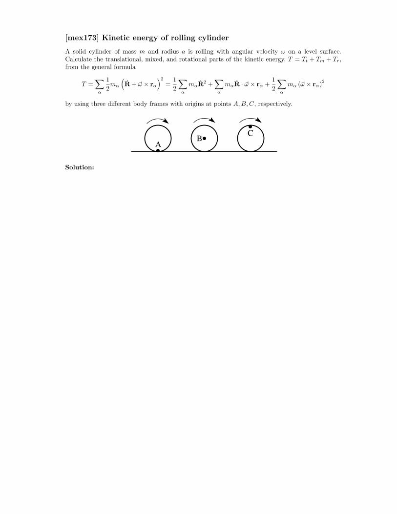
[mex173] Kinetic energy of rolling cylinder
A solid cylinder of mass m and radius a is rolling with angular velocity ω on a level surface.Calculate the translational, mixed, and rotational parts of the kinetic energy, T = Tt + Tm + Tr,from the general formula
T =∑α
1
2mα
(R + ~ω × rα
)2=
1
2
∑α
mαR2 +
∑α
mαR · ~ω × rα +1
2
∑α
mα (~ω × rα)2
by using three different body frames with origins at points A,B,C, respectively.
C
AB
Solution:

Principal Axes of Inertia [mln80]
The inertia tensor I is real and symmetric. Hence it has real eigenvalues.
The orthogonal transformation which diagonalizes the inertia tensor is arotation of the body coordinate axes to the directions of the principal axes.
The eigenvalue problem,
I · ~ωk = Ik ~ωk, k = 1, 2, 3,
amounts to a system of linear, homogeneous equations,
I11ω1k + I12ω2k + I13ω3k = I1ω1k
I21ω1k + I22ω2k + I23ω3k = I2ω2k
I31ω3k + I32ω3k + I33ω3k = I3ω3k,
where the principal moments of inertia Ik, k = 1, 2, 3 are the roots of thecharacteristic polynomial,∣∣∣∣∣∣
I11 − Ik I12 I13
I21 I22 − Ik I23
I31 I32 I33 − Ik
∣∣∣∣∣∣ = 0.
The three eigenvectors ~ωk, k = 1, 2, 3 have undetermined magnitude.If normalized, we construct an orthonormal matrix from them:
Ω = (~ω1, ~ω2, ~ω3) =
ω11 ω12 ω13
ω21 ω22 ω23
ω31 ω32 ω33
.
In matrix notation the transformation to principal axes looks as follows:
I · Ω = Ω · I ⇒ ΩT · I · Ω = ΩT · Ω · I = I,
where
I =
I11 I12 I13
I21 I22 I23
I31 I32 I33
, I =
I1 0 00 I2 00 0 I3
,
ΩT · Ω =
1 0 00 1 00 0 1
.

[mex69] Parallel-axis theorem
Consider a rigid body composed of particles with mass mα whose relative positions have constantmagnitude. The total mass of the rigid body is
∑αmα =M . Two body coordinate systems with
parallel axes are labelled (r1, r2, r3) and (R1, R2, R3), respectively. The center of mass coordinateof the rigid body is (0, 0, 0) in the former and (a1, a2, a3) in the latter. Show that the inertia tensorof the rigid body in the displaced coordinate system, Iij , is obtained from the inertia tensor in the
center-of-mass system, I(cm)ij , by adding to it the inertia tensor of a point mass M at the position
of the center of mass:Iij = I
(cm)ij +M
(a2δij − aiaj
).
Solution:

[mex73] Perpendicular-axis theorem
Consider a homogeneous sheet of material which has infinitesimal thickness dx3 and some arbitrayshape in the (x1, x2)-plane. (a) Prove the following relation between the moments of inertia forrotations about the coordinate axes: I11 + I22 = I33. (b) Use the parallel-axis and perpendicular-axis theorems to calculate the principal moments of inertia I11, I22, I33 of a coin (mass M , radiusR) for rotations about the axes of the following coordinate system: The origin is at the rim of thecoin. The x1-axis is radial toward the center of the coin, the x2-axis is tangential to the coin, andthe x3-axis is perpendicular to the plane of the coin.
x1
x2
x3
x1
x2
x3
Solution:
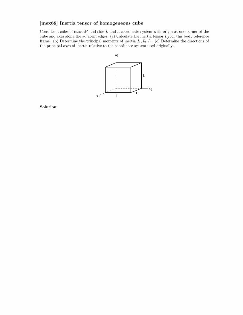
[mex68] Inertia tensor of homogeneous cube
Consider a cube of mass M and side L and a coordinate system with origin at one corner of thecube and axes along the adjacent edges. (a) Calculate the inertia tensor Iij for this body referenceframe. (b) Determine the principal moments of inertia I1, I2, I3. (c) Determine the directions ofthe principal axes of inertia relative to the coordinate system used originally.
L
x1
x2
x3
LL
Solution:

[mex252] Principal moments of solid cylinder
Calculate the principal moments of inertia I1, I2, I3 of a solid cylinder as functions of its mass M ,its radius R, and its height h for rotations about the center of mass..
Solution:

[mex253] Principal moments of a solid sphere.
Calculate the principal moments of inertia I1, I2, I3 of a solid sphere as a function of its mass Mand its radius R for rotations about the center of mass.
Solution:
[mex254] Principal moments of a solid ellipsoid
Calculate the principal moments I1, I2, I3 of a solid ellipsoid as functions of its mass M and itssemi-axes a, b, c for rotations about the center of mass.
Solution:

[mex255] Inertia tensor of four-atomic molecule
Consider a four-atomic molecule with the atoms at the corners of a pyramid. The base is anequilateral triangle of side a. The height is h. The three atoms at the base each have mass m1
and the atom at the tip has mass m2.(a) Find the principal moments of inertia I1, I2, I3 as functions of m1,m2, a, h for rotations aboutthe center of mass.(b) Identify the simplifications that occur when the pyramid is a regular tetrahedron of side a andall four masses are equal.
Solution:
[mex71] Inertia tensor of a cone
Calculate the principal moments of inertia for a homogeneous cone of mass M , height h, and radiusR at the base. Perform the calculation for rotations about an axis (a) through the apex of thecone, (b) through the center of mass. Express all results as functions of M,R, h.
Solution:

[mex143] Simulating a stick by three point masses
Consider a nonuniform rod with mass m and moment of inertia I0 for rotations about an axisthrough the center of mass and perpendicular to the axis of the rod. The moment of inertia forrotations about a parallel axis displaced by x is then Ix = I0 + mx2.Show that three point masses m0,m1,m2 with m0 +m1 +m2 = m in the configuration shown canbe chosen such that its moment of inertia for rotations about an axis through m0 is I0 and thatfor rotations about a parallel axis displaced by x is Ix just as is the case for the rod. Express thevalues of m0,m1,m2 as functions of the specifications m, I0, a, b of the rod.
x
cm
m1m
0m
2
ba
Solution:
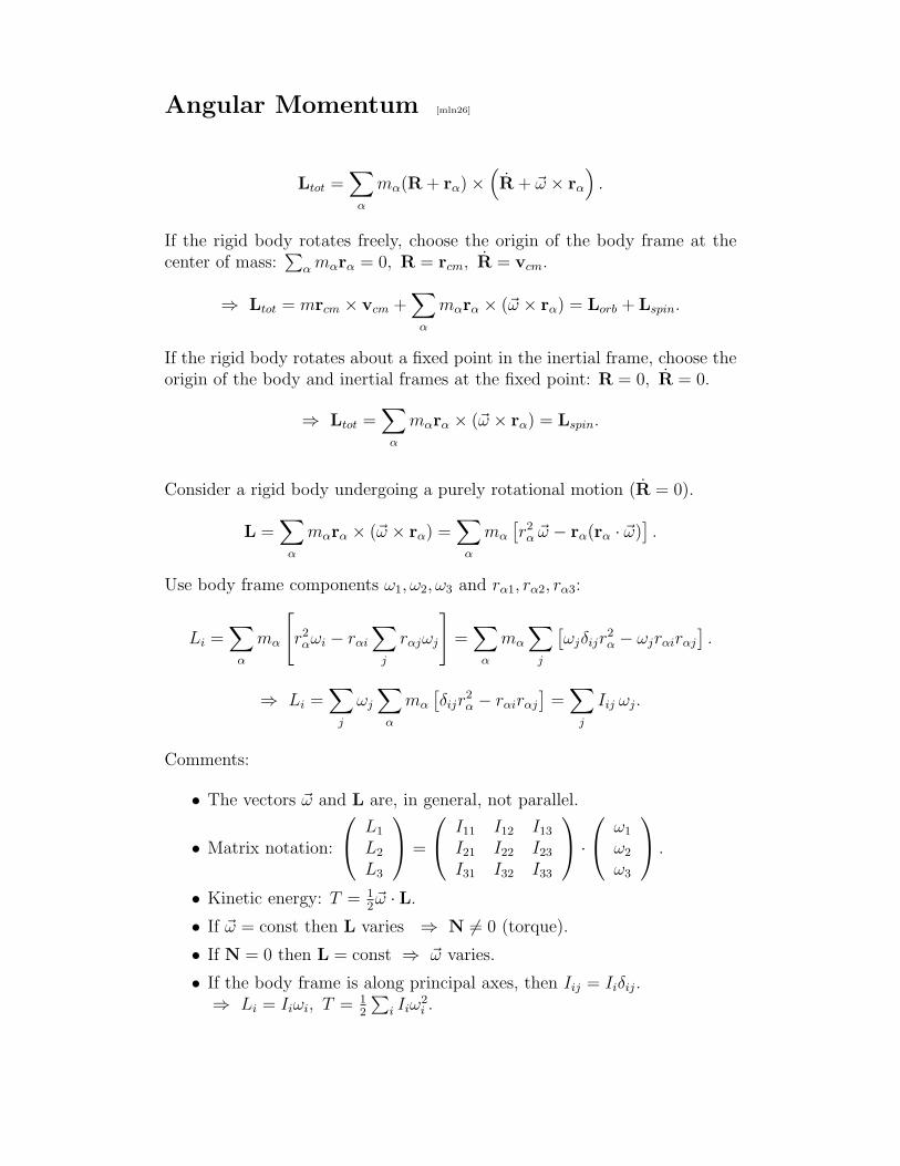
Angular Momentum [mln26]
Ltot =∑
α
mα(R + rα)×(R + ~ω × rα
).
If the rigid body rotates freely, choose the origin of the body frame at thecenter of mass:
∑α mαrα = 0, R = rcm, R = vcm.
⇒ Ltot = mrcm × vcm +∑
α
mαrα × (~ω × rα) = Lorb + Lspin.
If the rigid body rotates about a fixed point in the inertial frame, choose theorigin of the body and inertial frames at the fixed point: R = 0, R = 0.
⇒ Ltot =∑
α
mαrα × (~ω × rα) = Lspin.
Consider a rigid body undergoing a purely rotational motion (R = 0).
L =∑
α
mαrα × (~ω × rα) =∑
α
mα
[r2α ~ω − rα(rα · ~ω)
].
Use body frame components ω1, ω2, ω3 and rα1, rα2, rα3:
Li =∑
α
mα
[r2αωi − rαi
∑j
rαjωj
]=
∑α
mα
∑j
[ωjδijr
2α − ωjrαirαj
].
⇒ Li =∑
j
ωj
∑α
mα
[δijr
2α − rαirαj
]=
∑j
Iij ωj.
Comments:
• The vectors ~ω and L are, in general, not parallel.
• Matrix notation:
L1
L2
L3
=
I11 I12 I13
I21 I22 I23
I31 I32 I33
·
ω1
ω2
ω3
.
• Kinetic energy: T = 12~ω · L.
• If ~ω = const then L varies ⇒ N 6= 0 (torque).
• If N = 0 then L = const ⇒ ~ω varies.
• If the body frame is along principal axes, then Iij = Iiδij.⇒ Li = Iiωi, T = 1
2
∑i Iiω
2i .

Eulerian Angular Velocities [msl26]
The rotation of a rigid body is described by the vector ~ω of angular velocity.In general, this vector changes magnitude and direction in both coordinatesystems (x1, x2, x3) and (x′1, x
′2, x
′3).
The most natural formulation of the equations of motion for a rigid body isin the body frame (x1, x2, x3). They are called Euler’s equations.
However, the solution is incomplete unless we know how to express the vector~ω in the frame (x′1, x
′2, x
′3), which is typically the frame of the observer.
Eulerian angular velocities:
φ directed along z′-axis.θ directed along line of nodes.ψ directed along z-axis.
Projections onto axes of (x1, x2, x3):
ψ1 = 0, ψ2 = 0, ψ3 = ψ.θ1 = θ cosψ, θ2 = −θ sinψ, θ3 = 0.φ1 = φ sin θ sinψ, φ2 = φ sin θ cosψ, φ3 = φ cos θ.
Projections onto axes of (x′1, x′2, x
′3):
φ′1 = 0, φ′
2 = 0, φ′3 = φ.
θ′1 = θ cosφ, θ′2 = θ sinφ, θ′3 = 0.ψ′1 = ψ sin θ sinφ, ψ′
2 = −ψ sin θ cosφ, ψ′3 = ψ cos θ.
Instantaneous angular velocity in the frame (x1, x2, x3): ~ω = (ω1, ω2, ω3).
ω1 = φ1 + θ1 + ψ1 = φ sin θ sinψ + θ cosψ.ω2 = φ2 + θ2 + ψ2 = φ sin θ cosψ − θ sinψ.ω3 = φ3 + θ3 + ψ3 = φ cos θ + ψ.
Instantaneous angular velocity in the frame (x′1, x′2, x
′3): ~ω′ = (ω′
1, ω′2, ω
′3).
ω′1 = φ′
1 + θ′1 + ψ′1 = ψ sin θ sinφ+ θ cosφ.
ω′2 = φ′
2 + θ′2 + ψ′2 = −ψ sin θ cosφ+ θ sinφ.
ω′3 = φ′
3 + θ′3 + ψ′3 = ψ cos θ + φ.
Magnitude of angular velocity: |~ω|2 = |~ω′|2 = φ2 + θ2 + ψ2 + 2φψ cos θ.

[mex174] Rotating rectangular box
A rectangular box with principal moments of inertia I1 < I2 < I3 spins with angular velocityα about the y-axis of the body frame, which, in turn, rotates with angular velocity β about theZ-axis of the inertial frame. The origins of both coordinate systems are at the center of mass andthe axes of the two systems coincide at time t = 0. Find the rotational kinetic energy.
I y, Y
z, Z
x, X
I2
1
I 3
Solution:

Euler’s Equations [mln27]
Equation of motion in inertial frame:
(dL
dt
)I
= N.
Equation of motion in (rotating) body frame:
(dL
dt
)R
+ ~ω × L = N.
Proof:
N =d
dt
[∑α
mαrα × (~ω × rα)
]=
d
dt
[∑i
Liei
]=
d
dt
[∑ij
Iijωjei
].
Use ei = ~ω × ei. ⇒ N =∑ij
Iijωjei + ~ω ×∑ij
Iijωjei.
Choose body frame with principal coordinate axes: Li = Iiωi, i = 1, 2, 3.
Euler’s equations:
I1ω1 − ω2ω3(I2 − I3) = N1
I2ω2 − ω3ω1(I3 − I1) = N2
I3ω3 − ω1ω2(I1 − I2) = N3
A purely rotating rigid body has 3 degrees of freedom.The associated Lagrange equations are three 2nd order ODEs.
The solution via Euler’s equations proceeds in two steps:
1. Euler’s equations themselves are three 1st order ODEs for ω1, ω2, ω3.
2. The transformation to the inertial frame, ωi = ωi(φ, θ, ψ; φ, θ, ψ) amountsto solving another three 1st order ODEs.

[mex175] Heavy wheels
The axes of two wheels (solid disks of mass m and radius R) are free to bend vertically about pointO. A motor forces the axes to rotate with angular velocity ω about the vertical axis through Owhile the two wheels on the ground move in a circle of radius `. Find the normal force FN betweeneach wheel and the ground by performing the calculation (a) in the inertial frame and (b) in theframe rotating with the vertical axis.
O
FN
l
2R
Solution: