12 International Journal of Membrane Science and ...
10
12 International Journal of Membrane Science and Technology, 2016, 3, 12-21 E-ISSN: 2410-1869/16 © 2016 Cosmos Scholars Publishing House Theoretical Considerations of Pressure Drop and Mass Transfer of Gas Flow in Spiral Wound Membrane Modules M. Metaiche and J. Sanchez-Marcano * Institut Européen des Membranes, UMR 5635, ENSCM, CNRS, UM, cc 047, Place Eugène Bataillon, 34095 Montpellier, France Abstract: In this work we give the preliminary results of the development of two reliable correlations for the calculation of the friction and mass transfer coefficients for the gas transfer through spiral wound membrane modules. The mass transfer coefficient which allows determining the polarization phenomenon was taken in consideration through the calculation of the Sherwood number near the surface of the membranes. Both correlations take in consideration the inclination angle of transversal and longitudinal filaments of grids in spacers. They allow a good prediction of the pressure drop, friction coefficient and the mass transfer in spiral modules for gas flow when compared with experimental results obtained in a previous work reported in the literature. Keywords: Gas separation, Mass transfer, Membrane, Spiral wound module, Pressure drop. 1. INTRODUCTION The selective separation of gases and mainly CO 2 , is a challenge in many industrial fields like oil refining, cement and thermal production of electricity because this gas is certainly responsible of the accelerated greenhouse effect observed during the last thirty years. At large scale, the most used technologies for gas separation are adsorption and absorption processes. Nevertheless, the size of such units is generally considerable because the quantity of gases to be treated at industrial scale is generally very large. In addition, these technologies also involve high costs for maintenance and monitoring and present some problems like for example, for the absorption processes, the regeneration and final disposal of liquid absorbents. From a theoretical point of view, membrane processes provide a promising alternative for gas separation processes when compared, with classical technologies, because they are compact; requires little quantity of or no chemicals and little needs of maintenance and monitoring. In addition such processes are modular; this last characteristic allows a relatively easy scale up. Membrane plant sizes are relatively proportional to contaminants quantity to separate and this technology is therefore well suited for contaminant-rich flows. In addition, membrane technology is not greedy for energy. All of these advantages of membrane processes for gas separation contribute to an increasing consideration to their * Address correspondence to this author at the Institut Européen des Membranes, UMR 5635, ENSCM, CNRS, UM, cc 047, Place Eugène Bataillon, 34095 Montpellier, France; Tel: +33 467149149; Fax: +33 467149119; E-mail: [email protected] application in natural gas sector as well as in industries producing large quantities of CO 2 like oil and petro- chemical industry. More than 90% of market of membrane gas separation concerns the separation of nitrogen and oxygen from air; other separations like hydrogen/ nitrogen, hydrogen/argon, and hydrogen/methane have also been developed. This technology forms also a promising solution for natural gas treatment and carbon dioxide separation from industrial gaseous currents. Spiral wound membrane modules are widely used in water treatment field (desalination, wastewater treatment and nanofiltration) because they present many advantages like high mass transfer coefficient, compactness, relatively low costs etc. when compared with classical tubular configurations. However, until now they are not really used for gas separation, where hollow fibers are favored because fibers present the highest surface/volume ratio. Moreover, foremost of gas separation membranes are produced with vitreous polymers and the technology to manufacture hollow fibers with such polymers is very well-known. Nevertheless, rubbery membranes have been reported being very interesting for some gas separations like for permanent gases/organic vapors separation. In addition, the costs of rubbery materials are generally low when compared to vitreous polymers. Moreover, membranes manufactured with rubbery materials have also been reported to be a serious alternative to vitreous polymers for the separation of CO 2 from some gaseous currents [1-3]. These rubbery polymers are appropriate to manufacture spiral wound membranes because they can be easily applied on porous thin films which can be then manufactured as spiral wound modules.
Transcript of 12 International Journal of Membrane Science and ...

12 International Journal of Membrane Science and Technology, 2016, 3, 12-21
E-ISSN: 2410-1869/16 © 2016 Cosmos Scholars Publishing House
Theoretical Considerations of Pressure Drop and Mass Transfer of Gas Flow in Spiral Wound Membrane Modules
M. Metaiche and J. Sanchez-Marcano*
Institut Européen des Membranes, UMR 5635, ENSCM, CNRS, UM, cc 047, Place Eugène Bataillon, 34095 Montpellier, France
Abstract: In this work we give the preliminary results of the development of two reliable correlations for the calculation of the friction and mass transfer coefficients for the gas transfer through spiral wound membrane modules. The mass transfer coefficient which allows determining the polarization phenomenon was taken in consideration through the calculation of the Sherwood number near the surface of the membranes. Both correlations take in consideration the inclination angle of transversal and longitudinal filaments of grids in spacers. They allow a good prediction of the pressure drop, friction coefficient and the mass transfer in spiral modules for gas flow when compared with experimental results obtained in a previous work reported in the literature.
Keywords: Gas separation, Mass transfer, Membrane, Spiral wound module, Pressure drop.
1. INTRODUCTION
The selective separation of gases and mainly CO2, is a challenge in many industrial fields like oil refining, cement and thermal production of electricity because this gas is certainly responsible of the accelerated greenhouse effect observed during the last thirty years. At large scale, the most used technologies for gas separation are adsorption and absorption processes. Nevertheless, the size of such units is generally considerable because the quantity of gases to be treated at industrial scale is generally very large. In addition, these technologies also involve high costs for maintenance and monitoring and present some problems like for example, for the absorption processes, the regeneration and final disposal of liquid absorbents.
From a theoretical point of view, membrane processes provide a promising alternative for gas separation processes when compared, with classical technologies, because they are compact; requires little quantity of or no chemicals and little needs of maintenance and monitoring. In addition such processes are modular; this last characteristic allows a relatively easy scale up. Membrane plant sizes are relatively proportional to contaminants quantity to separate and this technology is therefore well suited for contaminant-rich flows. In addition, membrane technology is not greedy for energy. All of these advantages of membrane processes for gas separation contribute to an increasing consideration to their
*Address correspondence to this author at the Institut Européen des Membranes, UMR 5635, ENSCM, CNRS, UM, cc 047, Place Eugène Bataillon, 34095 Montpellier, France; Tel: +33 467149149; Fax: +33 467149119; E-mail: [email protected]
application in natural gas sector as well as in industries producing large quantities of CO2 like oil and petro- chemical industry.
More than 90% of market of membrane gas separation concerns the separation of nitrogen and oxygen from air; other separations like hydrogen/ nitrogen, hydrogen/argon, and hydrogen/methane have also been developed. This technology forms also a promising solution for natural gas treatment and carbon dioxide separation from industrial gaseous currents. Spiral wound membrane modules are widely used in water treatment field (desalination, wastewater treatment and nanofiltration) because they present many advantages like high mass transfer coefficient, compactness, relatively low costs etc. when compared with classical tubular configurations. However, until now they are not really used for gas separation, where hollow fibers are favored because fibers present the highest surface/volume ratio. Moreover, foremost of gas separation membranes are produced with vitreous polymers and the technology to manufacture hollow fibers with such polymers is very well-known. Nevertheless, rubbery membranes have been reported being very interesting for some gas separations like for permanent gases/organic vapors separation. In addition, the costs of rubbery materials are generally low when compared to vitreous polymers. Moreover, membranes manufactured with rubbery materials have also been reported to be a serious alternative to vitreous polymers for the separation of CO2 from some gaseous currents [1-3]. These rubbery polymers are appropriate to manufacture spiral wound membranes because they can be easily applied on porous thin films which can be then manufactured as spiral wound modules.
Pressure Drop and Mass Transfer of Gas Flow in Spiral Wound International Journal of Membrane Science and Technology, 2016, Vol. 3, No. 1 13
As described above, spiral wound modules are well known for their good performances in water treatment applications where they are currently used, are the most commercialized and also are the most inexpensive. They present very good mass transfer properties, provide good membrane resistance and have good compaction. However, the special geometry of these modules can be a source of polarization problems because it is difficult to maintain good hydrodynamics conditions between the films which form the spiral wound. Existence of spacers in this type of modules, promote the mass transfer because they contribute to disrupt the flow, to reduce the boundary layer thickness and the polarization layer thickness [4]. Generally, the spacers are considered as vortex promoters, enhancing the permeation flow through membranes [5]. These effects have been demonstrated experimentally in works concerning the permeation of aqueous solutions [6-8].
The objective of this study is to present the evaluation of the pressure drop and the mass transfer during the flow of gases into spiral wound membrane modules using a pressure drop coefficient and the Sherwood number. For this purpose we built correlations able to simulate the effect of the inclination angle of spacer filaments into a spiral module on pressure drop and mass transfer (Figure 1). The developed correlations have been validated with the experimental results reported by Zimmerer and Kottke [9] for the separation of ammonia traces from an air current in one spiral-wound module. This work is one of the very rare studies of gas permeation through spiral-wound modules reported in the literature.
2. THEORETICAL CONSIDERATIONS
2.1. Pressure Drop
The pressure drop during flow of fluids through a channel can be described according to Darcy-Weisbach law. It is inversely proportional to density ! and hydraulic diameter hd , and proportional to square
average velocity 2u , characteristic length l, and a coefficient ! which is equivalent to the pressure drop coefficient (λ is also called friction coefficient):
!P = " u 2 .l2#.dh
(1)
this λ coefficient can be also written as:
! = 2."P.#.dhu 2 .l
(2)
the modeling of the pressure drop consists to model the behavior of this λ coefficient at different hydrodynamic conditions. For a fluid forced flow, λ depends essentially on the turbulence, viscosity, and roughness. The relation between turbulence flow and fluid viscosity is expressed by the classical Reynolds number Re:
Re =2u .dh!
(3)
where u is the average flow velocity, dh the hydraulic diameter and ν the kinematics fluid viscosity.
For flow into a spacer of spiral membrane (Figure 1), transversal filaments are placed not only to separate membrane sheets but also to create some turbulence. These filaments have the same or a close size of flow thickness, and even if their influence is much more important than classical roughness in a pipe, we take the assumption that irregularities caused by the filaments represent the roughness. In addition, the inclination angle between transversal and longitudinal filaments has certainly a direct effect on roughness amplification. Under these conditions, the flow can be considered as highly rough. Theoretical analysis conducted by Hagen-Poiseuille [10] for a laminar flow ( Re < 2000 ) showed that only turbulence and viscosity have effects on pressure drop coefficient (velocities are low for this type of flow, and the effect of roughness becomes negligible):
! = 64Re
(4)
colebrook and White [11] and Colebrook [12] gave a general model showing effects of Reynolds number and roughness at 2000Re > , for liquid flow into roughened pipes:
1!
= "2.log 2.51Re !
+ 0.27 #dh
$
%&
'
() (5)
where !dh
concerns the relative roughness of the pipe.
Blasius [10] showed that for a not very turbulent flow ( 510Re < ) the most adapted model correlation is:
! = 100.Re( )"0.25 (6)

14 International Journal of Membrane Science and Technology, 2016, Vol. 3, No. 1 Metaiche and Marcano
whereas, for a very turbulent regime ( Re > 105 ), the Karman-Prandlt-Nikuradse model [10] gives relation- ship between Reynolds number and pressure drop coefficient:
1!= 2.log Re. !"# $% & 0.8 = 2.log
Re !2.51
(7)
the Colebrook-White model expressed as transcendental equation has been simplified by Swamee and Jain in order to obtain the following correlation for liquid flow in rough pipes [13]:
! = 0.25
log "3.7dh
+ 5.74Re0.9
#
$%
&
'(
)*+
,+
-.+
/+
2 (8)
shock and Miquel [8] studied the liquid flow through a high rough area formed by an spiral membrane (for
510Re2000 << ) and noted that the more adequate correlation has a Balsius type as the correlation reported in the monograph of Noble and Stern [14]:
! = 6.23Re"0.3 (9)
However, Shock and Miquel correlation doesn’t take into account the inclination angle of filaments.
2.2. Mass Transfer in Boundary Layer
The gas transfer through spiral dense membranes takes place mainly by diffusion and convection. The diffusive transfer takes place in the separative layer according to Fick’s law, while the convective transfer takes place in the boundary layer near the membrane surface. The transfer flux for one species is described by Bird [15]:
Ji = k.!i .ln1" cmi /!i1" cfi /!i
#
$%%
&
'((
(10)
where imc is the concentration of the component i in the boundary layer and fic the concentration of the
component i, in the free fluid region, φ is calculated as follows:
!i =JiJi" (11)
and k is the mass transfer coefficient which is given by:
k = D!
(12)
where D is the diffusivity and δ the boundary layer thickness.
The boundary layer coefficient can also expressed by the following equation:
k = Sh.Ddh
(13)
where Sh is the Sherwood number.
Therefore, the modeling of mass transfer in a boundary layer is reduced to calculate the behavior of the Sherwood number which is by definition function of Reynolds number and Schmidt number Sc, according to the general following relation [16]:
Sh = a.Reb .Scc (14)
here a, b, c are correlation coefficients and Sc the Schmidt number which measures the ratio between the kinematic viscosity ! and the diffusivity:
Sc = !D
(15)
equation (14) can be considered as a general equation in which only the values of α coefficients change depending on the membrane module geometry (hollow fibers, tubular, flat etc.) and Reynolds number for water transport through membrane modules [17-20].
Sieder and Tate [21], showed that for water flow in tubular module for laminar regime under the condition
of 30 < Re.Sc.dhl
< 104 ; the Sherwood number can be
calculated by the very well-known Levêque equation [22]:
Sh = 1.62. Re.Sc. dhl
!"#
$%&1/3
(16)
in their study of binary gas mixtures separation through flat and hollow fiber membranes Beuscher and Gooding [23] suggested similar correlations but with different coefficients for the case of gas transport through membrane modules of different geometries (hollow fiber and flat membranes).
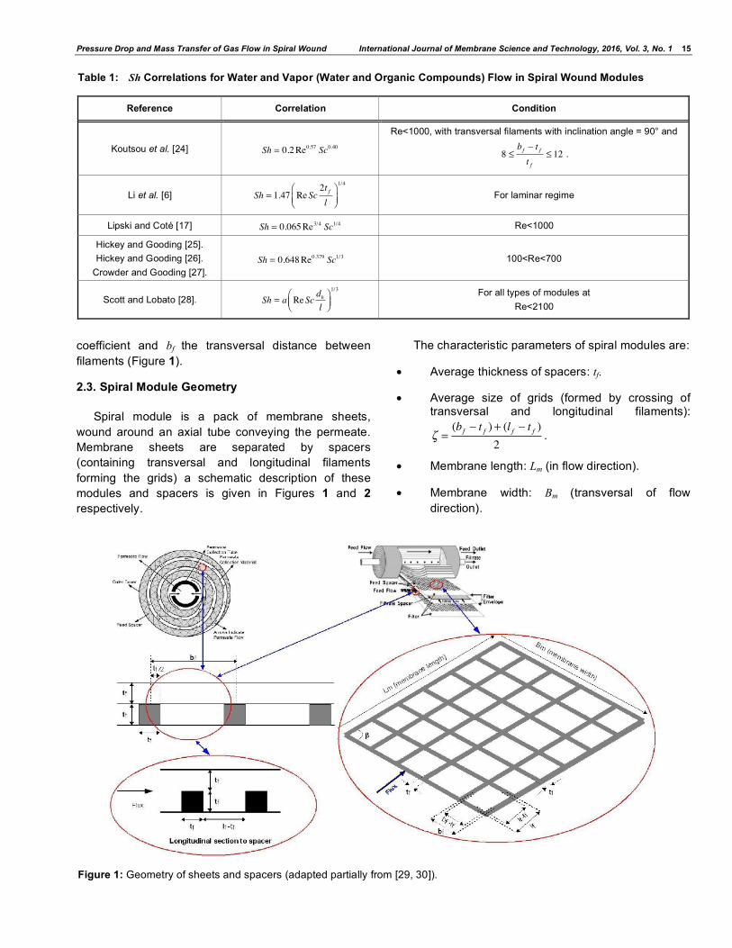
For water and vapor (water and organic compounds) flow in spiral modules with spacer grids, (Figures 1 and 2) similar type of correlations have been developed, they are summarized in Table 1.
In these correlations tf is the diameter or the thickness of filaments, l the characteristic length, a a
Pressure Drop and Mass Transfer of Gas Flow in Spiral Wound International Journal of Membrane Science and Technology, 2016, Vol. 3, No. 1 15
coefficient and bf the transversal distance between filaments (Figure 1).
2.3. Spiral Module Geometry
Spiral module is a pack of membrane sheets, wound around an axial tube conveying the permeate. Membrane sheets are separated by spacers (containing transversal and longitudinal filaments forming the grids) a schematic description of these modules and spacers is given in Figures 1 and 2 respectively.
The characteristic parameters of spiral modules are:
• Average thickness of spacers: tf.
• Average size of grids (formed by crossing of transversal and longitudinal filaments):
! =(bf " t f ) + (l f " t f )
2.
• Membrane length: Lm (in flow direction).
• Membrane width: Bm (transversal of flow direction).
Table 1: Sh Correlations for Water and Vapor (Water and Organic Compounds) Flow in Spiral Wound Modules
Reference Correlation Condition
Koutsou et al. [24] Sh = 0.2Re0.57 Sc0.40
Re<1000, with transversal filaments with inclination angle = 90° and
8 !bf " t ft f
! 12 .
Li et al. [6] Sh = 1.47 ReSc2t fl
!"#
$%&
1/4
For laminar regime
Lipski and Coté [17] Sh = 0.065Re3/4 Sc1/4 Re<1000
Hickey and Gooding [25]. Hickey and Gooding [26].
Crowder and Gooding [27]. Sh = 0.648Re0.379 Sc1/3 100<Re<700
Scott and Lobato [28]. Sh = a ReScdhl
!"#
$%&1/3
For all types of modules at
Re<2100
Figure 1: Geometry of sheets and spacers (adapted partially from [29, 30]).

16 International Journal of Membrane Science and Technology, 2016, Vol. 3, No. 1 Metaiche and Marcano
• Membrane active surface: S.
• Inclination angle between filaments: ! .
• The number of membrane sheets by module.
Figure 2: Geometry of grids considered in this work.
There are several definitions of the hydraulic diameter dh. We considered in this work the definition of Zimmerer and Kottke [1]:
dh =8 ! 4" #
$4mB+ 1#+ 2" 1! #
mB%&'
()*. 1$
(17)
where ! =t f2
and ! =l f " t f2
+bf " t f2
2.4. Other Considerations
This study considers the geometrical dimensions and operation data reported by Zimmerer and Kottke [1], for an air flow containing ammonia traces, through spacers of one spiral module, at 3.5 atm of feed pressure, and a temperature of 25°C. In their work these authors used a membrane sheet of 1.5 10-1 m of width and 4.0 10-1 m of length whereas the filament presented a thickness of 5.0 10-3 m. In terms of hydrodynamics conditions they used a Reynolds number of 1000. For the calculation of the drop pressure coefficient ! we considered here that the absolute roughness was equal to the thickness of transversal filaments. For each value of inclination angle β and for each value of Reynolds number, we calculated the value of ! coefficient and then we plotted ! = f (Re,") .
For the calculation of Sherwood number we calculated first the Schmidt number. In this context, we considered the value of diffusion coefficient of ammonia in air, this diffusion coefficient was measured by Spiller [31] (0.228.10-4 m2/s at 25°C and 1 atm). This diffusion coefficient value is close to the value reported by Ivakin and Suetin [32] (0.247.10-4 m2/s at 25°C).
The dynamic viscosity of ammonia at 20°C is 9.82.10-6 Pa.s (with Sutherland coefficient equal to 370 K) was obtained from tables [33]. The Sutherland law is used to calculate the dynamic viscosity at 25°C [34]. The ammonia density was calculated considering the ideal gas law.
For each value of flow through the length l, and for each value of inclination angle β, we calculated the Sherwood number, we plot the curves Sh = f (l,!) , and we compared our theoretical curves with the experi- mental values reported by Zimmerer and Kottke [1].
RESULTS AND DISCUSSION
Preliminary calculations were carried out for the evolution of the friction coefficient λ in function of the Reynolds number and for different β angles of the grids using the models of Shock and Miquel [8], Blasius [10], and Swamee and Jain [13]. These results were compared with the experimental results already reported [1]. From Figure 3 which shows the compari- son between calculated and experimental results we can clearly observe that previous reported models don’t represent well experimental variation of λ in function of Reynolds number.
These preliminary results shows that existing correlations are not adequate to represent correctly the experimental variation of the pressure drop in a spiral wound module containing spacers with different angles of grids. The models of Swamee and Jain and Shock and Miquel gives average values but they are not sensitive to the variation of the inclination angle of the grids. In addition, the Shock and Miquel and Blasius models are straight lines, so they do not follow the curvature of experimental points which is much more noticeable when the inclination angles becomes important (60° and 75°). As far as these models are not able to represent correctly the experimental results we developed a new correlation in order to represent better the variation of pressure drop coefficient ! in function of roughness and Reynolds number. This new correlation takes in consideration the advantage of the Swamee and Jain model which is given as an algebraic

Pressure Drop and Mass Transfer of Gas Flow in Spiral Wound International Journal of Membrane Science and Technology, 2016, Vol. 3, No. 1 17
equation unlike Colebrook and White model (equation (5)) and Karman-Prandlt-Nikuradse model (equation (7)) which is given as a transcendental equation.
We took a first the assumption that the spacer roughness is equal to transversal filament thickness. Secondly we started from the simplification made by Swamee and Jain of the Colebrook-White model [13] (equation (8)) in order to obtain the following equation:
! = x
logt f3.7dh
+ 5.74Rey
"
#$
%
&'
()*
+*
,-*
.*
2 (18)
where x and y are correlation coefficients which are function of the inclination angle ! (in radian). The calculation of x and y coefficients made using least squares method for different values of ! gives:
x = 12.314.exp(!4.414")
y = 0.92 ! 0.22"
now equation (18) can be written as :
! = 12.314.exp("4.414#)
logt f3.7dh
+ 5, 74Re0.92"0.22#
$
%&
'
()
*+,
-,
./,
0,
2 (19)
This correlation gives the pressure drop coefficient ! of a gas flow in a spiral module, in function of the transversal filament thickness tf, the hydraulic diameter dh, the Reynolds number, and the inclination angle ! between transversal and longitudinal filaments.
The comparison between experimental results [1] and theoretical results obtained with this equation above are presented in Figure 4. We can notice that the theoretical curves obtained match well experimen- tal points for a large range of Reynolds number from laminar to turbulent regimes until Re= 10 000. This result confirms hypothesis that flow through spacers is a high rough flow.
To determine the Sherwood number correlation in the boundary layer of gas flow inside spacers we can take in consideration the theoretical approach given in the introduction of this work. Then, Sherwood number correlation can be written in function of Reynolds number Re, Schmidt number Sc, hydraulic diameter dh, characteristic length l and inclination angle between filaments ! . As a first approximation we can take the assumption that this correlation takes the general form given below:
Sh = m. Re .Sc.dh( )1/3 + n (20)
where m and n are correlation coefficients and are function of the characteristic length l and inclination
Figure 3: Plot of the evolution of λ versus Re at different β angles. Comparison between calculated results with the models (color lines) of Shock and Miquel [8], Blasius [10] and Swamee and Jain [13] with experimental results of Zimmerer and Kottke [1] (points).

18 International Journal of Membrane Science and Technology, 2016, Vol. 3, No. 1 Metaiche and Marcano
angle between filaments ! . The calculation of m and n can be carried out using least square method, for different values of l and ! we obtain:
m = 22.5
n = !15, 285." + 0, 029.ln(") + 0, 0136[ ] / l
now equation (20) can be written as:
Sh = 22, 5. Re.Sc.dh[ ]1/3 !15, 285." + 0, 029.ln(") + 0, 0136[ ] / l (21)
where ! is given in radian, l and dh in meters.
Figure 5 compares the evolution of the Sherwood number in function of the characteristic length at different Reynolds numbers calculated with the correlation (21) developed above. For comparison we plotted the results reached with other models described
Figure 4: Comparison between the model (this work) and experimental results of Zimmerer and Kottke [1] for the variation of λ in function of Reynolds at different angles of grid rods and for gas flow in a spiral wound module.
Figure 5: Comparison between the calculation of Sherwood number from different correlations (Lipski and Coté (1990), Levêque (1928), Koutsou et al. (2009) and Li et al. (2002) and this work for ! =60°) and for different values of Reynolds number (500, 700 and 1000).

Pressure Drop and Mass Transfer of Gas Flow in Spiral Wound International Journal of Membrane Science and Technology, 2016, Vol. 3, No. 1 19
in the introduction (models developed for liquid flow in spiral modules): Lipski and Coté [17], Levêque [22], Koutsou et al. [24] and Li et al. [29].
We can notice that Lipski and Coté [17] and the correlation (21) developed in this work are the more responsive models to the variation of the Sherwood number in function of the Reynolds number. The results reached with both models and correlations have a good sensitivity for the membrane module studied because they are in good agreement with the fact that the mass transfer coefficient and then the Sherwood number have to increase with the Reynolds number enhancement under the hydrodynamic conditions studied. Models of Levêque [22], Koutsou et al. [24] and Li et al. [29] present a small or no variation of the Sherwood number when the Re varies between 500 and 1000.
Even if the correlations of this work seem to be very responsive to the variation of the Reynolds number it is important to analyze its capability to represent experimental results and then its validity. Figure 6 shows the comparison between the modeling of Sherwood number in function of the characteristic length calculated by this model through equation (21) and experimental results of Zimmerer and Kottke [1] at different angles (reported in degrees) of grid rods and for gas flow in a spiral wound module. We can notice that the semi-empirical correlation (21) matches well the experimental results. This result confirms the good capability of this model to calculate the Sherwood number and then the mass transfer coefficient on a spiral wound module for gas separation.
Results of Zimmerer and Kottke (1996) (points) for different inclination angle of the grids and a Reynolds number of 1000 (gas flow).
CONCLUSIONS
During this study, we give the results of the development of correlations for gas flow in spiral wound membrane modules: one for pressure drop coefficient, and the other for Sherwood number evolution in function of some geometrical or operating parameters.
These correlations which have been validated with the experimental results of a gaseous binary mixture from the literature are interesting because they take in consideration the inclination angle of transversal and longitudinal filaments of grids in spacers, a fundamental dimension to decrease the polarization phenomena. Moreover, they give a good prediction of the pressure drop and the mass transfer in spiral modules for gas flow while giving a good estimation of boundary layer and polarization concentration phenomena through the calculation of the mass transfer coefficient in function of the hydrodynamics. It is worth noting that there are very few reported works of permanent gas separation with spiral wound modules, but the number of interesting reports with elastomers, well adapted to this configuration, like copolymers of PEO for CO2 separation is increasing in the literature. It should be then interesting to validate these theoretical results with more complex mixtures of gases (more than two components) in order to generalize the possible application of elastomers to gas
Figure 6: Comparison between our model of Sherwood number (solid lines) and experimental.

20 International Journal of Membrane Science and Technology, 2016, Vol. 3, No. 1 Metaiche and Marcano
separation at large range of hydrodynamic conditions and different size and angles of grids. The obtained results, will therefore contribute to study progress and calculation of gas separation parameters: enrichment and impoverishment rates (purification and elimination), which allows the good design of membrane systems for gas separation.
LIST OF SYMBOLS
a Correlation coefficient
b Correlation coefficient
c Correlation coefficient
Bm Membrane width (m)
bf Transversal width of the grid (m)
cfi Molar fraction (concentration) of the component i, in free fluid region
cmi Molar fraction (concentration) of the component i in the boundary layer
D Diffusivity and the boundary layer thickness (m2/s)
dh Hydraulic diameter (m)
Ji Transfer flux of species i (m/s)
k Mass transfer coefficient (m/s)
l Characteristic length (m)
Lm Membrane length (m)
lf Longitudinal length of grid (m)
m Correlation coefficient
n Correlation coefficient
r Tube radius (m)
Re Reynolds number (-)
S Membrane active surface (m2)
Sc Schmidt number (-)
Sh Sherwood number (-)
tf Filament thickness (m)
u Average fluid velocity (m/s)
x Correlation coefficient
y Correlation coefficient
! Inclination angle between transversal and longitudinal filaments (radian)
! Boundary layer thickness (m)
!i Molar fraction of species i
ΔP Pressure drop (Pa)
ε Absolute roughness (m)
λ Friction coefficient
ν Kinematics viscosity (m2/s)
ρ Fluid density (Kg/m3)
χ Filament thickness/2 (m)
ζ Average size of grids (m)
REFERENCES
[1] Sanchez J, Gramain Ph, Membranes for selective gas separation. Patents: FR 2814088, 25/01/2002. EP1322409, 02/07/2003. US 7339008, 04/03/2008.
[2] Sanchez J, Charmette C, Gramain Ph, Poly (ethylene oxide-co-epichlorhydrin) membranes for carbon dioxide separation; J Membrane Sci 2002; 205 : 259-263. http://dx.doi.org/10.1016/S0376-7388(02)00124-2
[3] Charmette C, Sanchez J, Gramain Ph, Rudatsikira A, Gas transport properties of poly (ethylene oxide-co-epichlorohydrin) membranes; J. Membrane Sci 2004; 230: 161-169. http://dx.doi.org/10.1016/j.memsci.2003.10.043
[4] Yang G, Xing W, Xu N, Concentration polarization in spiral-wound nanofiltration membrane elements, Desalination 2003; 154: 89-99. http://dx.doi.org/10.1016/S0011-9164(03)00210-8
[5] Li F, Meindersma W, De Haan AB, Reith T, Optimization of commercial net spacers in spiral wound membrane modules, J Membrane Sci 2002; 208: 289-302. http://dx.doi.org/10.1016/S0376-7388(02)00307-1
[6] Farkova J, The pressure drop in membrane module with spacers, J Membrane Sci 1991; 64: 103-111. http://dx.doi.org/10.1016/0376-7388(91)80081-G
[7] Schock G, Miquel A, Mass transfer and pressure drop in spiral wound modules, Desalination 1987; 64: 339-352. http://dx.doi.org/10.1016/0011-9164(87)90107-X
[8] Shen JJS, Probstein RF, Turbulence promotion and hydrodynamic optimization in an ultrafiltration process, Ind Eng Chem Process Des Dev 1979; 18: 547-554. http://dx.doi.org/10.1021/i260071a033
[9] Zimmerer CC, Kottke V, Effects of spacer geometry on pressure drop, mass transfer, mixing behavior, and residence time distribution, Desalination 1996; 104: 129-134. http://dx.doi.org/10.1016/0011-9164(96)00035-5
[10] Carlier M. Hydraulique Générale et appliquée. Paris: Eyrolles; 1980.
[11] Colebrook CF, White CM, Experiments with Fluid Friction in Roughened Pipes, Proc. Royal Soc. of London, Series A, Math Phys Sci 1937; 161: 367-381. http://dx.doi.org/10.1098/rspa.1937.0150
[12] Colebrook CF, Turbulent flow in pipes with particular reference to the transition region between smooth and rough pipe laws, J Inst Civil Eng 1939; 133-156. http://dx.doi.org/10.1680/ijoti.1939.13150
[13] Swamee PK, Jain AK, Explicit equations for pipe-flow problems, J Hydraul Div (ASCE) 1976; 102: 657-664.
Pressure Drop and Mass Transfer of Gas Flow in Spiral Wound International Journal of Membrane Science and Technology, 2016, Vol. 3, No. 1 21
[14] Noble RD, Stern SA. Membrane Separations Technology: Principles and Applications, 1st Edition. Amsterdam: Elsevier Science 1995.
[15] Bird RB, Stewart WE, Lightfoot EN. Transport phenomena, 2nd Ed., New York: Wiley; 2002.
[16] Dobre T, Sanchez Marcano J. Chemical Engineering, Modelling, Simulation and Similitude, Weinheim: Wiley VCH; 2007.
[17] Lipski C, Coté P. The Use of Pervaporation for the Removal of Organic Contaminants from Water, Environ Prog 1990; 9: 254-261. http://dx.doi.org/10.1002/ep.670090420
[18] Mulder M. Basic Principles of Membrane Technology. 1st Edition. The Netherlands: Kluwer Academic Publishers; 1991. http://dx.doi.org/10.1007/978-94-017-0835-7
[19] Dotremont C, Van den Ende S, Vandommele H, Vandecasteele C. Concentration Polarization and Other Boundary-Layer Effects in the Pervaporation of Chlorinated Hydrocarbons, Desalination 1994; 95: 91-113. http://dx.doi.org/10.1016/0011-9164(94)00008-5
[20] Bandini, S, Saavedra A, Sarti GC, Vacuum Membrane Distillation: Experiments and Modeling, AIChE Journal 1997; 43: 398-408. http://dx.doi.org/10.1002/aic.690430213
[21] Sieder EN, Tate GE, Heat transfer and pressure drop of liquids in tubes. Ind Eng Chem Res 1936; 28: 1429-1436. http://dx.doi.org/10.1021/ie50324a027
[22] Levêque MA, Les Lois de la Transmission de Chaleur par Convection, Ann Mines 1928; 13: 201-299.
[23] Beuscher U, Gooding CH, The infuence of the porous support layer of composite membranes on the separation of binary gas mixtures. J Membrane Sci 1999; 152: 99-116. http://dx.doi.org/10.1016/S0376-7388(98)00205-1
[24] Koutsou CP, Yiantsios SG, Karabelas AJ, A numerical and experimental study of mass transfer in spacer-filled channels: Effects of spacer geometrical characteristics and Schmidt
number, J Membrane Sci 2009; 326: 234-251. http://dx.doi.org/10.1016/j.memsci.2008.10.007
[25] Hickey PJ, Gooding C. Mass transfer in spiral wound pervaporation modules, J Membrane Sci 1994; 92: 59-74. http://dx.doi.org/10.1016/0376-7388(94)80013-8
[26] Hickey PJ, Gooding C. Modeling spiral wound membrane modules for the pervaporative removal of volatile organic compounds from water, J Membrane Sci 1994; 88: 47-68. http://dx.doi.org/10.1016/0376-7388(93)E0166-H
[27] Crowder ML, Gooding C, Spiral wound, hollow fiber membrane modules: A new approach to higher mass transfer efficiency, J Membrane Sci 1997; 137: 17- 29. http://dx.doi.org/10.1016/S0376-7388(97)00174-9
[28] Scott. K, Lobato J, Determination of a Mass-Transfer Coefficient Using the Limiting-Current Technique, Chem Ed 2002; 7: 214-219.
[29] Li YL, Tung KL, The effect of curvature of a spacer-filled channel on fluid flow in spiral- wound membrane modules, J Membrane Sci 2008; 319: 286-297. http://dx.doi.org/10.1016/j.memsci.2008.03.069
[30] Geraldes V, Semiao V, De Pinho MN, Flow management in nanofiltration spiral wound modules with ladder-type spacers, J Membrane Sci 2002; 203: 87-102. http://dx.doi.org/10.1016/S0376-7388(01)00753-0
[31] Spiller LL, Determination of Ammonia/Air Diffusion Coefficient Using Nafion Lined Tube, Anal Lett 1989; 22: 2561-2573. http://dx.doi.org/10.1080/00032718908052375
[32] Ivakin BA, Suetin PE, Diffusion coefficients of some gases measured by the optical method, Soviet Phys Tech Phys 1964; (English Transl) 8: 748-751.
[33] Weast RC. Handbook of Chemistry and Physics. 65th edition. Boca Raton, Florida: CRC Press, Inc; 1984.
[34] Van de Ven JD, Li PY, Liquid piston gas compression, Appl Energy 2009; 86: 2183-2191. http://dx.doi.org/10.1016/j.apenergy.2008.12.001
Received on 01-04-2016 Accepted on 12-05-2016 Published on 31-05-2016 http://dx.doi.org/10.15379/2410-1869.2016.03.01.02
© 2016 Metaiche and Marcano; Licensee Cosmos Scholars Publishing House. This is an open access article licensed under the terms of the Creative Commons Attribution Non-Commercial License (http://creativecommons.org/licenses/by-nc/3.0/), which permits unrestricted, non-commercial use, distribution and reproduction in any medium, provided the work is properly cited.