12 ethernet-wifi
49
Week 12 Ethernet WiFi
-
Upload
olivier-bonaventure -
Category
Engineering
-
view
546 -
download
0
Transcript of 12 ethernet-wifi

Week 12Ethernet
WiFi
Agenda
• Ethernet
• Spanning Tree
• WiFi
• IP version 4

Ethernet Frames
• DIX Format
• proposed by Digital, Intel and Xerox
Preamble[8 bytes]
Destination address
Type[2 bytes]
CRC [32 bits]
Source address
Data[46-1500 bytes
Used to mark the beginning of the frameAllows the receiver to synchronise its
clock to the sender’s clock
Indication of the type of packet containedinside the frame
Upper layer protocol must ensure thatthe payload of the Ethernet frame is
at least 46 bytes and at most 1500 bytes

The Ethernet zoo
10BASE5 Thick coaxial cable, 500m
10BASE2 Thin coaxial cable, 185m
10BASE-T Two pairs of category 3+ UTP
10BASE-F 10 Mb/s over optical fiber
100BASE-TX Category 5 UTP or STP, 100 m maximum
100BASE-FX Two multimode optical fiber, 2 km maximum
1000BASE-CX Two pairs shielded twisted pair, 25m maximum
1000BASE-SX Two multimode or single mode optical fibers with lasers
10 Gbps optical fiber but also cat 6 twisted pair
40-100 Gbps being developed, standard expected in 2010, 40Gbps one
meter long for switch backplanes, 10 meters for copper cable and 100 meters for fiber optics
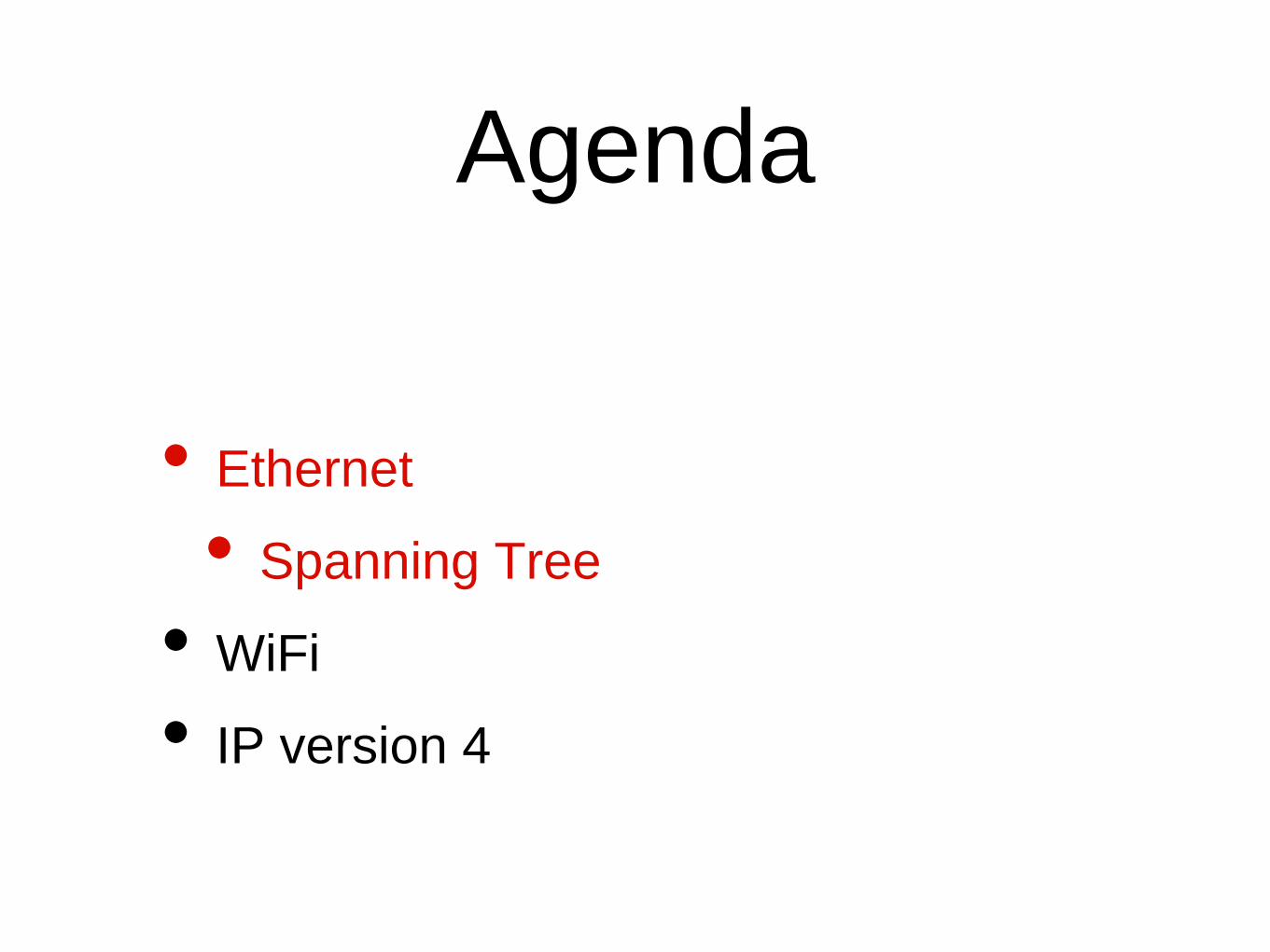
Ethernet switch
• A switch is a relay that operates in the datalink layer
Host A Host BSwitch
Physical Phys. Phys.
Datalink
Network Network
Datalink
Physical
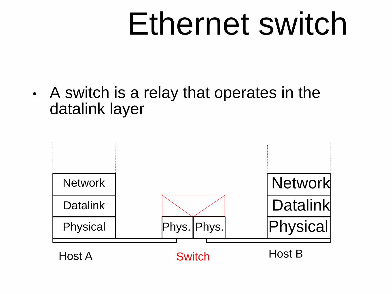
How to favour high-
speed links ?
Switch 1
Switch 7
Switch 9
Switch 22
Switch 44
Switch 2

Link costs
BandwidthRecommended
link cost range
Recommended
link cost value
10 Mbps 50-600 100
100 Mbps 10-60 19
1000 Mbps 3-10 4

Selection of root
• Root priority vectors
• Port 1: 8,7+100,9
• Port 2 : 8,9+1,22
• Port 3 : 8,4+10,17
• Port 4: 8,4+10,18
S911
234
R=8,C=7,T=9
R=8,C=9,T=22
R=8,C=4,T=17R=8,C=4,T=18
• Switch S91's BPDU
• R=8, C=10,T=91

Switches and hubs
• How should the spanning tree work with
hubs ?
S11
4
Hub1S3
1
2
Hub2
2

The states of the
ports• Root port
• Port having the best root priority vector
• Only one root port per switch !
• Designated port
• Ports where the switch's BPDU is better than best BDPU received
• Blocked ports
• Ports where the switch's BPDU is worse than best BDPU received
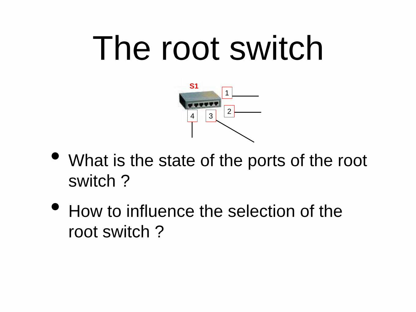
The root switch
• What is the state of the ports of the root
switch ?
• How to influence the selection of the
root switch ?
S11
234

Corner cases
• Parallel links
• Backup links to same LAN
S2S31
2 3
4
S1
2 4
S1

Spanning tree
1
234 1
1
1
1
2
22
2
3
3
3
4S222S111
S333
S444
S555
1 Gbps, cost =10
10 Gbps, cost =1

BPDU format• Simplified BPDU format
BPDU Header
Root Id
Switch identifier
Root path cost
Protocol IdentifierProtocol version
Configuration BPDU or topology changeFlags
Identifier of the switch sending the BPDU
Port identifier : used when a switch has severalports attached to the same LAN
Current root identifier
Port identifier
Message age
Max age
Hello time
Forward delay

Port states and
activityReceive
BPDUs
Transmit
BPDUs
Blocked yes no
Root yes no
Designated yes yes
Learn
Addresses
Forward Data
Frames
Inactive no no
Active yes yes
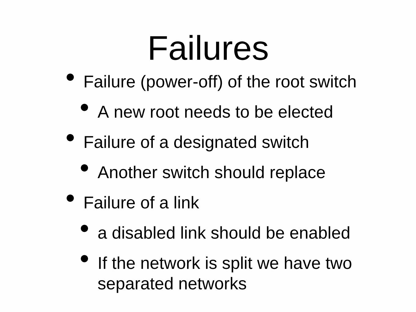
Failures• Failure (power-off) of the root switch
• A new root needs to be elected
• Failure of a designated switch
• Another switch should replace
• Failure of a link
• a disabled link should be enabled
• If the network is split we have two
separated networks
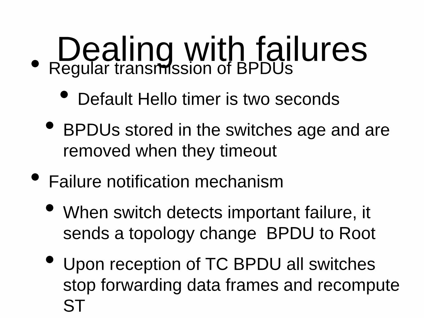
Dealing with failures• Regular transmission of BPDUs
• Default Hello timer is two seconds
• BPDUs stored in the switches age and are
removed when they timeout
• Failure notification mechanism
• When switch detects important failure, it
sends a topology change BPDU to Root
• Upon reception of TC BPDU all switches
stop forwarding data frames and recompute
ST

Full duplex Ethernet
ObservationsIn many networks, Ethernet is a often a point-to-point technology
host-to-switchswitch to switch
Twisted-pairs and fiber-based physical layers allow to send and receive at the same time
S1 S2
HUBHUB

Ethernet full duplex
No collision is possible on a full duplex Ethernet/FastEthernet/GigabitEthernet link
Disable CSMA/CD on such links
AdvantagesImproves bandwidth
Both endpoints can transmit frames at the same time
CSMA/CD is disabled
No constraint on propagation delay anymoreEthernet network can be as large as we want !
No constraint on minimum frame size anymoreWe do not need the frame extension hack for Gigabit Ethernet!

Full duplex Ethernet (3)
DrawbackIf CSMA/CD is disabled, access control is disabled and congestion can occur
How to solve this problem inside Ethernet ?Add buffers to switches
but infinite buffers are impossible and useless anywayCause collisions (e.g. jamming) to force collisions on the inter-switch link and uplink is server is too fast
Drawback : interswitch link could be entirely blockedDevelop a new flow control mechanism inside MAC layer
Pause frame to slowdown transmission
S1 S2Server
Client
FastEthernet (100 Mbps) Ethernet (10 Mbps)

Ethernet flow control
PAUSE frame indicates how much time the upstream should wait before transmitting next frame
S1
serverClient
FastEthernet(100 Mbps)
Ethernet(10 Mbps)
PAUSE [2msec]
Frame1 [10000 bits]
Frame3 [10000 bits]
Frame2 [10000 bits]
100 nsec
Frame1 [10000 bits]
1 microsec
Frame2 [10000 bits]
Sender blocked

Virtual LANs
Allows to build several logical networks on top of a single physical network
S
A B
C
D
F
E
Each port on each switch is associated to a particular VLANAll the hosts that reside on the same VLAN can exchange Ethernet framesA host on VLAN1 cannot send an Ethernet frame towards another host that belongs to VLAN2Broadcast and multicast frames are only sent to the members of the VLAN
VLAN1 : A,E,FVLAN2 : B,C,D

VLANs in campus networks
How to support VLANs in a campus network
S1
A B
C
D
F
E
VLAN1 : A,E,FVLAN2 : B,C,D
S2
Possible solutionsPlace on each switch a tablethat maps each MAC addresson a VLAN iddifficult to manage this table
Change frame format used on inter-switch links to include a VLAN identifiernew header added by first switchnew header removed by last switch

VLAN frame format
DestinationAddress
Address
Identifies the frame as containing VLANtag
Tag control information contains two types of information :- VLAN identifier (12 bits) : up to 4094 different VLANs can be defined- Priority (3 bits) : indicates the importance of the frame and can be used by switches to provide a better service for some frames (e.g. Voice)
Type
CRC [32 bits]
Payload
VLAN Protocol Id
0x8100
Tag Control Info

Agenda
• Ethernet
• Spanning Tree
• WiFi
• IP version 4

The WiFi zoo
Standard Frequency Typical
throughput
Raw
bandwidth
Range in/out
(m)
802 .11 2.4 GHz 0.9 Mbps 2 Mbps 20 / 100
802 .11a 5 GHz 23 Mbps 54 Mbps 35 / 120
802 .11b 2.4 GHz 4.3 Mbps 11 Mbps 38 / 140
802 .11g 2.4 GHz 19 Mbps 54 Mbps 38 / 140
802 .11n 2.4 / 5 GHz 74 Mbps up to 600
Mbps
70 / 250
Source http://en.wikipedia.org/wiki/IEEE_802.11n

Practical issues with WLAN deployments
Home environment
A WLAN can interfere with the neighbour’s WLAN

Practical issues with WLAN deployments
Enterprise networks
One access point can interfere with other access pointsreduces significantly overall available bandwidth

The WiFi channel frequencies
WiFi standards operate on several frequencies called channels
Usually about a dozen channels
Why multiple channels ?Some channels my be affected by interference and have a lower performanceSome frequencies are reserved for specific usage in some countriesAllows frequency reuse when there are multiple WiFinetworks in the same area
Unfortunately, many home access points operate by default on the same factory set channel which causes interference and reduced bandwidth

WLAN in enterprise environments
What could be done to improve the performance of WLANs ?
Reduce interference as much as possibleTune channel frequencies Reduce transmission powerSimilar to techniques used in GSM networks
Recent deployments rely on centralized controllers and thin access points

802.11 frame format
Frame control[2 bytes]
Duration/Id[2 bytes]
Address 2[6 bytes]
Address 1[6 bytes]
Standard header- Protocol version [2 bits] : current version 0- Type [2 bits] : control / data / management frame- Subtype [2 bits] : specific subtype of frame- to DS [1 bit] : frame is sent to distribution system- from DS [1 bit] : frame is from distribution system- more fragment [1 bit] : used when packets are fragmented- Retry [1 bit] : retransmission - Power Management [1 bit] : used for power management fct- More data [1 bit] : indicates that there are other frames
for this station at the access point- WEP [1 bit] : 1 if frame has been encrypted with WEP- order [1 bit] : for strictly ordered class
Address 3[6 bytes]
Sequence control [2 bytes]
Frame body[0-2312 bytes]
Frame Check Sequence
Sequence number- 12 bits frame sequence number- 4 bits fragment number

Some 802.11 control frames
Frame control[2 bytes]
Duration[2 bytes]
Receiver address[6 bytes]
Frame Check Sequence
Frame control[2 bytes]
Duration[2 bytes]
Receiver address[6 bytes]
Frame Check Sequence
Transmitter address[6 bytes]
Frame control[2 bytes]
Duration[2 bytes]
Receiver address[6 bytes]
Frame Check Sequence
ACK frameRTS frame
CTS frame

IP over 802.11
Frame control
Duration/Id[2 bytes]
Address 2[6 bytes]
Address 1[6 bytes]
Address 3[6 bytes]
Sequence control [2 bytes]
IP packet
Frame Check Sequence
LLC/SNAP
0x800
LLC/SNAP- 4 bytes header
EtherType- 0x800 for IP, 0x86DD for IPv6

Agenda
• Ethernet
• Spanning Tree
• WiFi
• IP version 4

IP version 4
Ver IHL DS Total length
Payload
32 bits
ChecksumTTL Protocol
Flags FragmentOffset
20 bytesSource IP address
Identification
Destination IP address
Differentiated Services Byte used tospecify Quality of Service expected
for this packet
IP version used to encode header- current version is 4- IP version 6
Header length (default 20 bytes)
Maximum : 64 bytes for entire header including options
Binary flagsMore
Don't Fragment : Packet cannot be fragmented by
intermediate routersAllows to identify the “user” above
the IP layer (e.g. UDP, TPC, ...)Plays similar role to TCP port
numbers
Packet identificationused for fragmentation and
reassembly
Options
Optional header extension
Time to Live

IPv4 addresses
• 32 bits long, one address per interface
• Example
Notation 138.48.26.1/23 or
138.48.26.1 255.255.254.0
• All hosts that belong to the same subnetwork
can directly exchange frames through
datalink layer

ARP : Address
Resolution Protocol
IP: 10.0.1.9Eth : B
IP: 10.0.1.8Eth : C
IP: 10.0.1.11Eth : E
IP: 10.0.1.22Eth : A
10.0.1.22 needs to send an IP packet to 10.0.1.8
1
IP: 10.0.1.9Eth : B
IP: 10.0.1.8Eth : C
IP: 10.0.1.11Eth : E
IP: 10.0.1.22Eth : A
ARP : broadcast frame Addr Eth 10.0.1.8 ?
2
IP: 10.0.1.9Eth : B
IP: 10.0.1.8Eth : C
IP: 10.0.1.11Eth : E
IP: 10.0.1.22Eth : A
10.0.1.8 replies in an Ethernet frame and A knows the MAC address to sendits IP packet
3

ARP : frame formatPreamble[7 bytes]
Delimiter[1byte]
DestinationAddress
Type: 0x806
CRC [32 bits]
Source Address
MAC address of the sender
Broadcast : 111...111
Header
Sender MAC
Sender IP
Target MAC
Common header for all ARP frames- Hardware type Ethernet is 1- Protocol type , IP is 0x0800.- Hardware length : length of MAC address - Protocol length : length of network layer address -Operation : 1 for request, 2 for reply, 3 for RARP request, and 4 for RARP reply.
Target IP

ICMP version 4
Ver IHL DS
IP headerChecksumTTL Protocol
Source IP address
Identification
Destination IP address
Data
Type Code
Ver IHL DS Total length
ChecksumTTL Protocol
Flags FragmentOffset
Source IP address
Identification
Destination IP address
First 64 bits of payload
Flags FragmentOffset
Protocol=1 for ICMP
covers entire ICMP message
Additional information abouterror, type of error
Total length
Checksum
32 bits
ICMP headerType and Code indicate the type of
error detectedl Destination unreachable
lnetwork unreachablelhost unreachable
lprotocol unreachablelport unreachable
lfragmentation neededlsource route failed
lRedirectlParameter problem
lTime exceededlTTL exceeded
lreassembly time exceededlEcho requEast et Echo reply
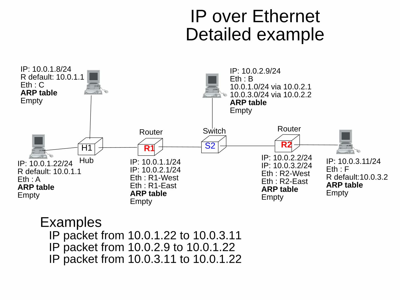
IP over Ethernet Detailed example
ExamplesIP packet from 10.0.1.22 to 10.0.3.11IP packet from 10.0.2.9 to 10.0.1.22IP packet from 10.0.3.11 to 10.0.1.22
IP: 10.0.2.9/24Eth : B10.0.1.0/24 via 10.0.2.110.0.3.0/24 via 10.0.2.2ARP tableEmpty
IP: 10.0.1.8/24R default: 10.0.1.1Eth : CARP tableEmpty
IP: 10.0.1.22/24R default: 10.0.1.1Eth : AARP tableEmpty
R1
IP: 10.0.1.1/24IP: 10.0.2.1/24Eth : R1-WestEth : R1-EastARP tableEmpty
H1 S2 R2
Hub
Router Switch Router
IP: 10.0.3.11/24Eth : FR default:10.0.3.2ARP tableEmpty
IP: 10.0.2.2/24IP: 10.0.3.2/24Eth : R2-WestEth : R2-EastARP tableEmpty
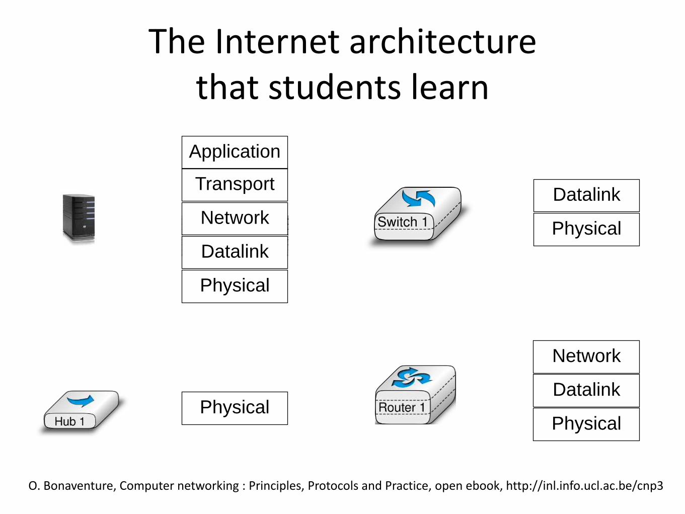
The Internet architecturethat students learn
Physical
Datalink
Network
Transport
Application
O. Bonaventure, Computer networking : Principles, Protocols and Practice, open ebook, http://inl.info.ucl.ac.be/cnp3
Physical
Physical
Datalink
Physical
Datalink
Network

A typical "academic" network
Physical
Datalink
Network
Transport
Application
Physical
Datalink
Network
Transport
Application
Physical
Datalink
Network
Physical
Datalink

The end-to-end principle
Physical
Datalink
Network
Transport
Application
Physical
Datalink
Network
Transport
Application
Physical
Datalink
Network
Physical
Datalink
TCP

In reality
– almost as many middleboxes as routers
– various types of middleboxes are deployed
Sherry, Justine, et al. "Making middleboxes someone else's problem: Network processing as a cloud service." Proceedings of the ACM SIGCOMM 2012 conference. ACM, 2012.

A middlebox zoo
http://www.cisco.com/web/about/ac50/ac47/2.html
Web Security Appliance
NAC Appliance
ACE XMLGateway
Streamer
VPN Concentrator
SSLTerminator
Cisco IOS Firewall
IP Telephony Router
PIX FirewallRight and Left
Voice GatewayVVVV
Content Engine
NAT

How to model those middleboxes ?
• In the official architecture, they do not exist
• In reality...
Physical
Datalink
Network
Transport
Application
Physical
Datalink
Network
Transport
Application
Physical
Datalink
Network
TCP
Physical
Datalink
Network
Transport
Application

TCP segments processed by a router
Source port Destination port
Checksum Urgent pointer
THL Reserved Flags
Acknowledgment number
Sequence number
Window
Ver IHL ToS Total length
ChecksumTTL Protocol
Flags Frag. Offset
Source IP address
Identification
Destination IP address
Payload
Options
Source port Destination port
Checksum Urgent pointer
THL Reserved Flags
Acknowledgment number
Sequence number
Window
Ver IHL ToS Total length
ChecksumTTL Protocol
Flags Frag. Offset
Source IP address
Identification
Destination IP address
Payload
Options
IP
TCP
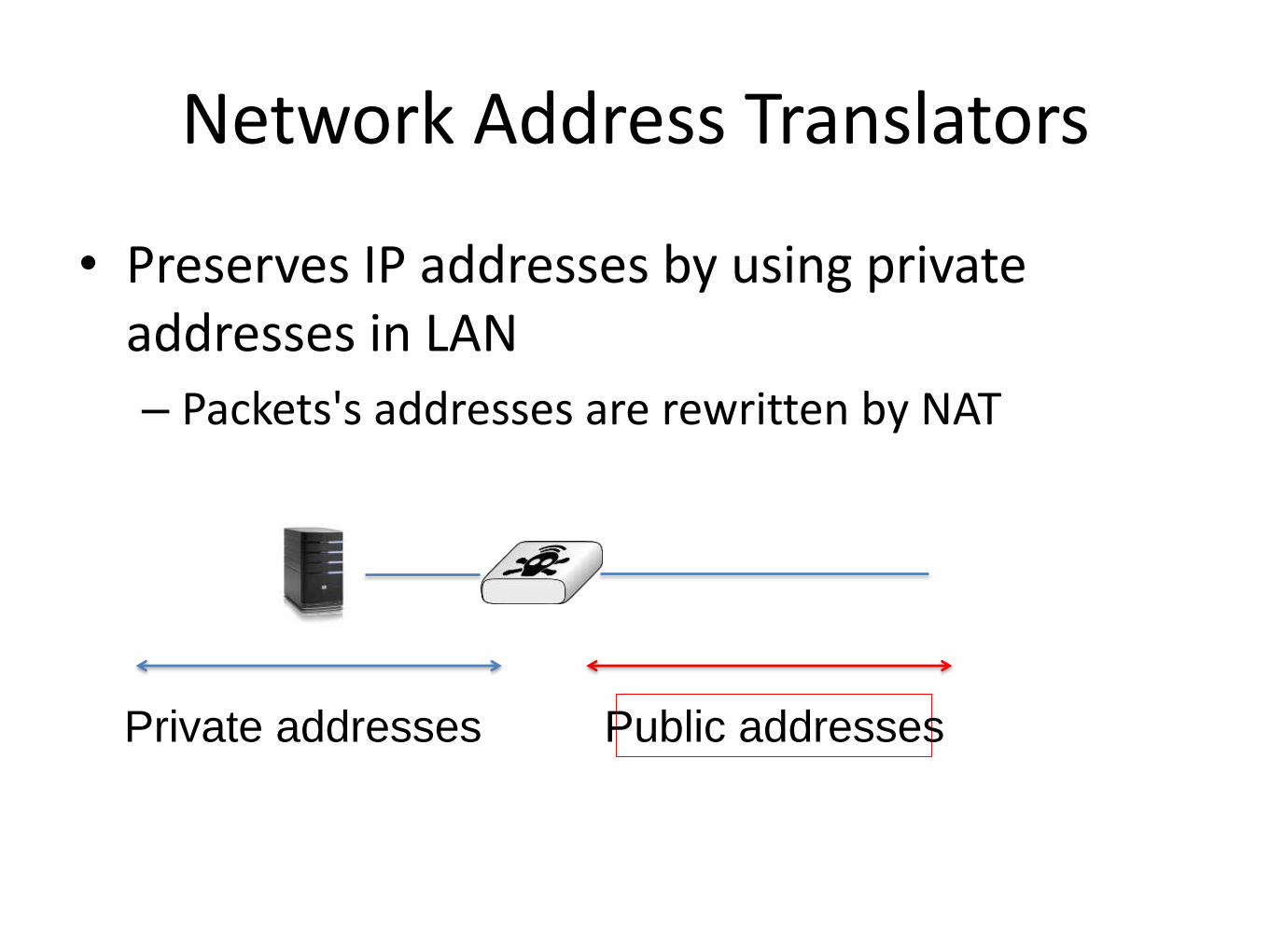
Network Address Translators
• Preserves IP addresses by using private addresses in LAN
– Packets's addresses are rewritten by NAT
Private addresses Public addresses

TCP segments processed by a NAT
Source port Destination port
Checksum Urgent pointer
THL Reserved Flags
Acknowledgment number
Sequence number
Window
Ver IHL ToS Total length
ChecksumTTL Protocol
Flags Frag. Offset
Source IP address
Identification
Destination IP address
Payload
Options
Source port Destination port
Checksum Urgent pointer
THL Reserved Flags
Acknowledgment number
Sequence number
Window
Ver IHL ToS Total length
ChecksumTTL Protocol
Flags Frag. Offset
Source IP address
Identification
Destination IP address
Payload
Options