1.2 EMU Electronics
43
1.2 EMU Electronics 1.2 EMU Electronics L.S. Durkin CMS Review CERN, September 2003
description
1.2 EMU Electronics. L.S. Durkin CMS Review CERN, September 2003. Outline. Overview of EMU Electronics System Status of EMU Electronics 25 ns Beam Test Results Future Plans Summary. cathode strips. 3 - 16 mm. avalanche. wires. Cathode plane. wires. cathode plane. cathode - PowerPoint PPT Presentation
Transcript of 1.2 EMU Electronics
1.2 EMU Electronics1.2 EMU Electronics
L.S. Durkin
CMS Review CERN, September 2003
L.S. Durkin, CMS Review, September 2003 2
OutlineOutlineOutlineOutline
• Overview of EMU Electronics System
• Status of EMU Electronics
• 25 ns Beam Test Results
• Future Plans
• Summary
L.S. Durkin, CMS Review, September 2003 3
Cathode Strip ChambersCathode Strip ChambersCathode Strip ChambersCathode Strip Chambers
cathode strips
Cathode plane
wiresavalanche3 - 16 mm
cathodestrips
wires
avalanche
cathode plane
9.5 mm
3.1 mmmuon
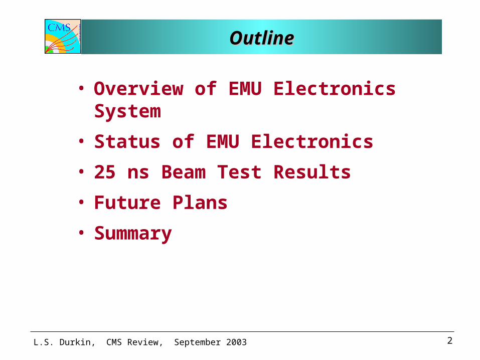
• 6-layer chambers
• Radial, trapezoidal cathode strips
• Azimuthal anode wires
• Induced charges on strips - precise coordinate
• Closely spaced wires - fast timing
• Wires ganged in groups of 5 -16 for r coordinate
L.S. Durkin, CMS Review, September 2003 4
Functions of ElectronicsFunctions of ElectronicsFunctions of ElectronicsFunctions of Electronics
• Acquire precise muon data for off-line analysis– Cathode strips: precise -coordinate (bending
direction) determination in each layer by interpolation of induced strip charges.
– Anode wire groups: precise timing for bunch crossing tagging and radial position determination.
• Generate primitives for Level-1 Trigger– Identify Local Charged Track (LCT) segments
using cathode and anode signals
L.S. Durkin, CMS Review, September 2003 5
Front-end RequirementsFront-end RequirementsFront-end RequirementsFront-end Requirements
• Cathode Electronics– (total signal)/(per channel noise) : 100/1– peaking time of shaped
pulse: 100 ns– digitization precision: 12 bits– dynamic range: 15 MIPs – non-linearity: < 1%
• Anode Electronics– peaking time shaped pulse: 30 ns– time slew of discriminated pulses: 2 ns
L.S. Durkin, CMS Review, September 2003 6
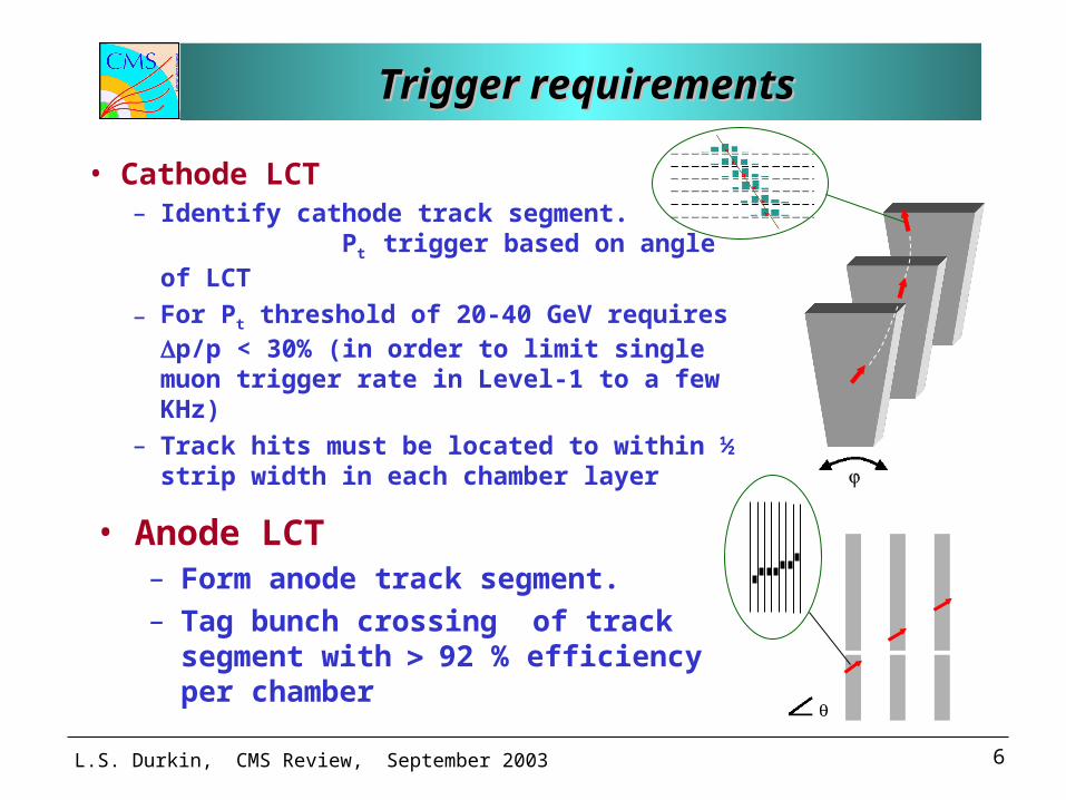
Trigger requirementsTrigger requirements Trigger requirementsTrigger requirements
• Cathode LCT– Identify cathode track segment.
Pt trigger based on angle of LCT
– For Pt threshold of 20-40 GeV requires p/p < 30% (in order to limit single muon trigger rate in Level-1 to a few KHz)
– Track hits must be located to within ½ strip width in each chamber layer
• Anode LCT– Form anode track segment.– Tag bunch crossing of track segment
with92 % efficiency per chamber
L.S. Durkin, CMS Review, September 2003 7
The LHC EnvironmentThe LHC EnvironmentThe LHC EnvironmentThe LHC Environment
• Charge Particle Rates in EMU– Punch through, hadrons, muons: Rates range from 10
Hz cm-2 (outer ME 3,4) to 300 Hz cm-2 (inner ME1)– Random hits induced by neutrons and photons: Rates can
be as high as 500 Hz cm-2 (inner ME1)
(Calculations based on TDR shielding)
• Radiation Levels at the CSC’s Integrated over 10 LHC years (5x10⁷ s at 1034 cm-2s-1)– Neutron Fluence (>100 keV): (0.02 - 6) x 1011 cm-2 – Total Ionizing Dose: (0.007 - 1.8) kRad
Levels at the iron disk peripheral about 10 times lower
(Calculations by M. Huhtinen)
L.S. Durkin, CMS Review, September 2003 8
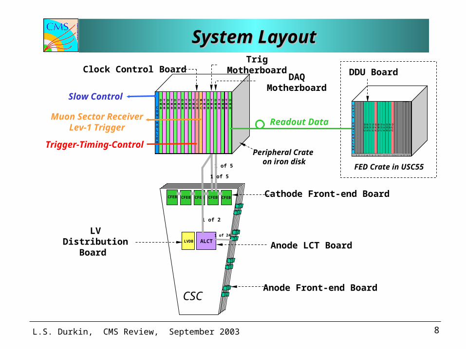
System LayoutSystem LayoutSystem LayoutSystem Layout
CSC
CFEBCFEBCFEB CFEB
ALCT1 of 24
CFEB
1 of 2
LVDBLV Distribution
Board
FED Crate in USC551 of 5
1 of 5
Anode Front-end Board
Cathode Front-end Board
Anode LCT Board
MPC
DMB
TMB
DMB
TMB
DMB
TMB
DMB
TMB
DMB
TMB
DMB
TMB
DMB
TMB
DMB
TMB
DMB
TMB
CCBC
ONTROLLER
Peripheral Crate on iron disk
Slow Control
Trigger-Timing-Control
Muon Sector ReceiverLev-1 Trigger
Trig Motherboard
DAQ Motherboard
Clock Control Board DDU Board
Readout Data
L.S. Durkin, CMS Review, September 2003 9
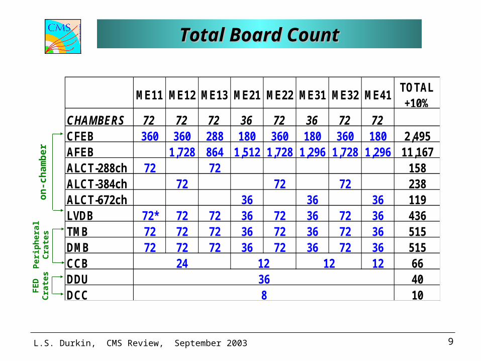
Total Board CountTotal Board CountTotal Board CountTotal Board Count
ME11 ME12 ME13 ME21 ME22 ME31 ME32 ME41TOTAL +10%
CHAMBERS 72 72 72 36 72 36 72 72CFEB 360 360 288 180 360 180 360 180 2,495AFEB 1,728 864 1,512 1,728 1,296 1,728 1,296 11,167ALCT-288ch 72 72 158ALCT-384ch 72 72 72 238ALCT-672ch 36 36 36 119LVDB 72* 72 72 36 72 36 72 36 436TMB 72 72 72 36 72 36 72 36 515DMB 72 72 72 36 72 36 72 36 515CCB 12 66DDU 40DCC 10
368
24 12 12
on
-ch
amb
er P
eri
ph
era
l C
rate
s F
ED
C
rate
s
L.S. Durkin, CMS Review, September 2003 10
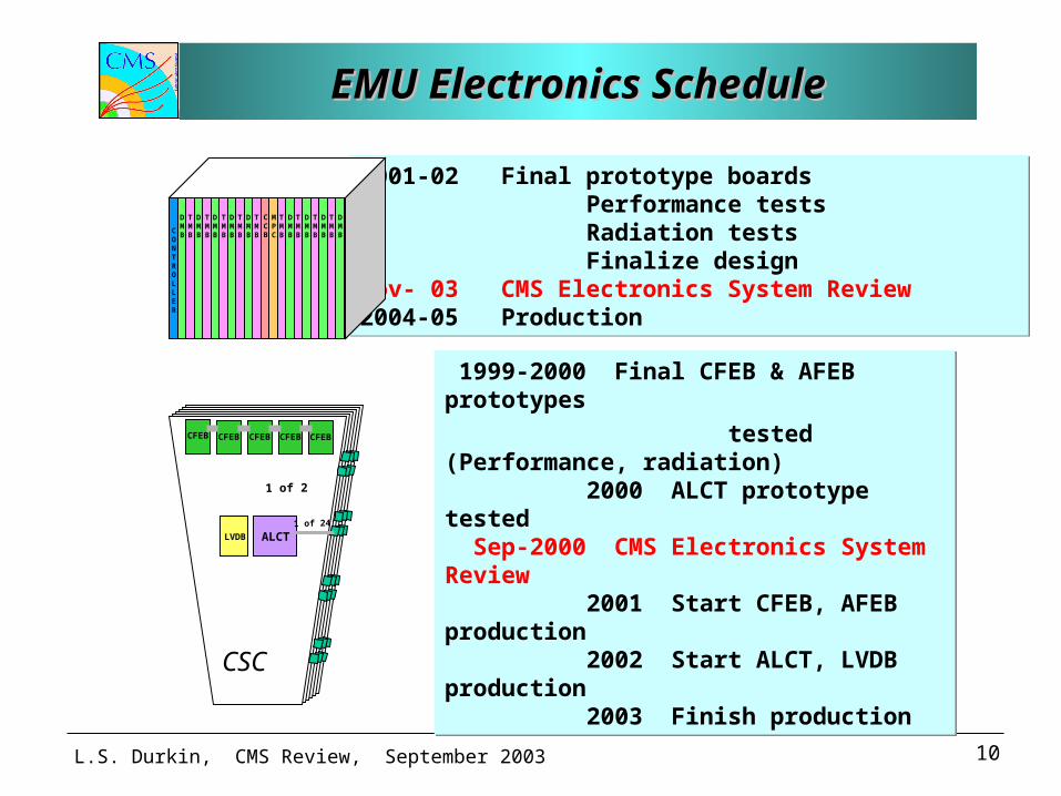
EMU Electronics ScheduleEMU Electronics ScheduleEMU Electronics ScheduleEMU Electronics Schedule
1999-2000 Final CFEB & AFEB prototypes
tested (Performance, radiation) 2000 ALCT prototype tested Sep-2000 CMS Electronics System Review 2001 Start CFEB, AFEB production 2002 Start ALCT, LVDB production 2003 Finish production
1999-2000 Final CFEB & AFEB prototypes
tested (Performance, radiation) 2000 ALCT prototype tested Sep-2000 CMS Electronics System Review 2001 Start CFEB, AFEB production 2002 Start ALCT, LVDB production 2003 Finish production
CSC
CFEBCFEBCFEB CFEB
ALCT1 of 24
CFEB
1 of 2
LVDB
2001-02 Final prototype boards Performance tests Radiation tests Finalize designNov- 03 CMS Electronics System Review2004-05 Production
2001-02 Final prototype boards Performance tests Radiation tests Finalize designNov- 03 CMS Electronics System Review2004-05 Production
MPC
DMB
TMB
DMB
TMB
DMB
TMB
DMB
TMB
DMB
TMB
DMB
TMB
DMB
TMB
DMB
TMB
DMB
TMB
CCB
CONTROLLER
L.S. Durkin, CMS Review, September 2003 11
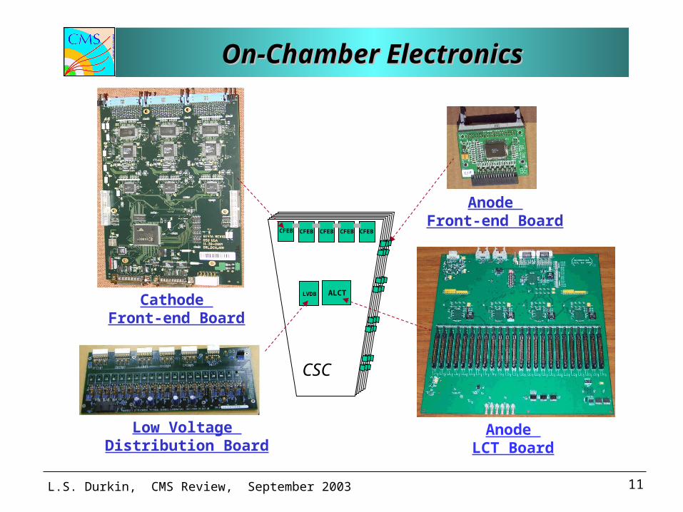
On-Chamber ElectronicsOn-Chamber ElectronicsOn-Chamber ElectronicsOn-Chamber Electronics
CSC
CFEBCFEBCFEB CFEB
ALCT
CFEB
LVDB
Cathode Front-end Board
Anode LCT Board
Anode Front-end Board
Low Voltage Distribution Board
L.S. Durkin, CMS Review, September 2003 12
Status: On-Chamber BoardsStatus: On-Chamber BoardsStatus: On-Chamber BoardsStatus: On-Chamber Boards
• Beam tests (GIF at CERN, 9/1999) of on-chamber boards showed that they met design specifications.
• Tests with 60 Mev protons and 1 MeV neutrons (UCD, OSU 5/2000) verified that the boards are tolerant to radiation at 3 times the calculated levels.
• Tests in magnetic fields (8/2000 at OSU, UCLA and FNAL) showed that the boards operate beyond 3.5 T.
• Spark protection circuits on CFEB and AFEB tested extensively with induced chamber sparks.
• Approved for production (CFEB, AFEB in 9/00; ALCT, LVDB in 11/01).
• Production of on-chamber boards is on schedule and within the budget.
L.S. Durkin, CMS Review, September 2003 13
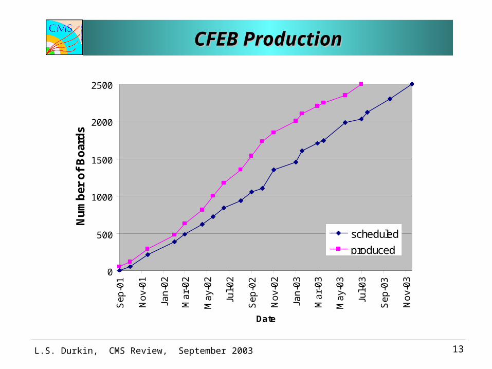
CFEB ProductionCFEB ProductionCFEB ProductionCFEB Production
0
500
1000
1500
2000
2500
Se
p-0
1
No
v-0
1
Jan
-02
Ma
r-0
2
Ma
y-0
2
Jul-
02
Se
p-0
2
No
v-0
2
Jan
-03
Ma
r-0
3
Ma
y-0
3
Jul-
03
Se
p-0
3
No
v-0
3
Date
Nu
mb
er o
f B
oar
ds
scheduled
produced
L.S. Durkin, CMS Review, September 2003 14
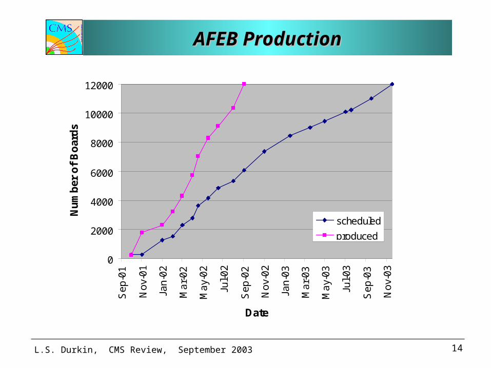
AFEB ProductionAFEB ProductionAFEB ProductionAFEB Production
0
2000
4000
6000
8000
10000
12000
Se
p-0
1
No
v-0
1
Jan
-02
Ma
r-0
2
Ma
y-0
2
Jul-
02
Se
p-0
2
No
v-0
2
Jan
-03
Ma
r-0
3
Ma
y-0
3
Jul-
03
Se
p-0
3
No
v-0
3
Date
Nu
mb
er o
f B
oar
ds
scheduled
produced
L.S. Durkin, CMS Review, September 2003 15
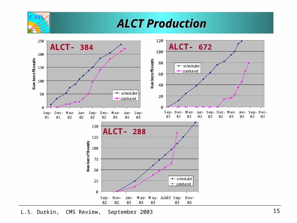
ALCT ProductionALCT ProductionALCT ProductionALCT Production
ALCT- 672ALCT- 384
ALCT- 288
L.S. Durkin, CMS Review, September 2003 16
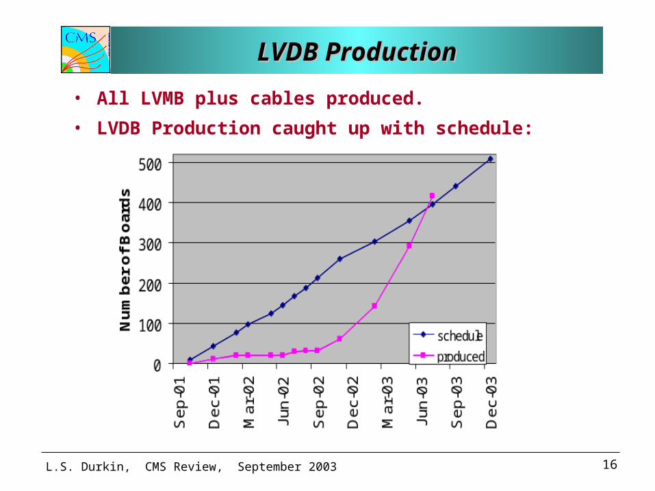
LVDB ProductionLVDB ProductionLVDB ProductionLVDB Production
• All LVMB plus cables produced.
• LVDB Production caught up with schedule:
L.S. Durkin, CMS Review, September 2003 17
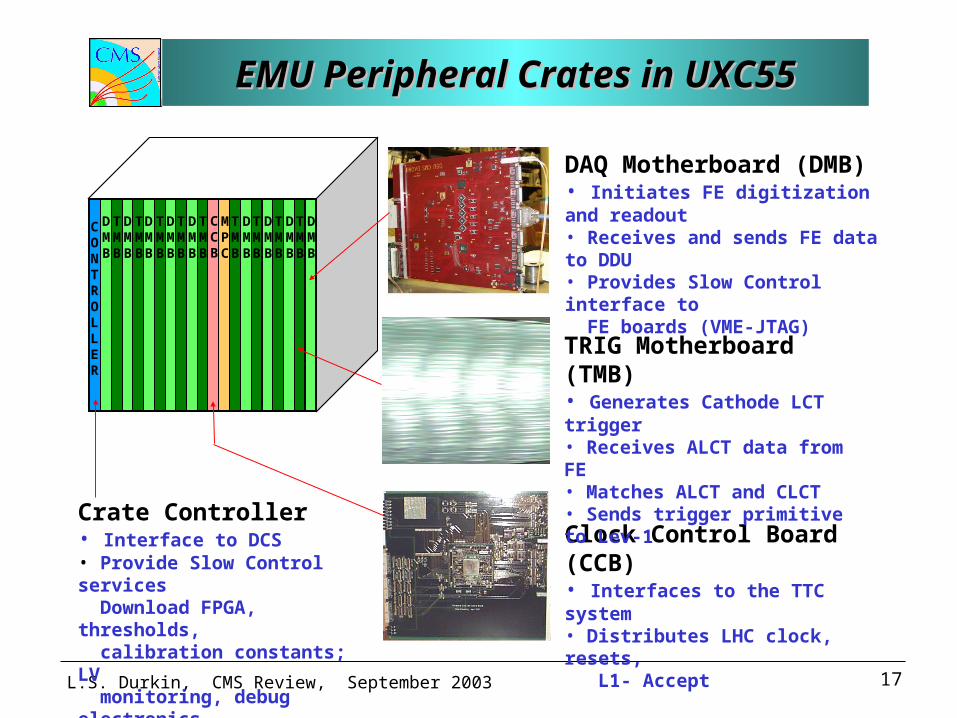
EMU Peripheral Crates in UXC55EMU Peripheral Crates in UXC55EMU Peripheral Crates in UXC55EMU Peripheral Crates in UXC55
MPC
DMB
TMB
DMB
TMB
DMB
TMB
DMB
TMB
DMB
TMB
DMB
TMB
DMB
TMB
DMB
TMB
DMB
TMB
CCB
CONTROLLER
Crate Controller• Interface to DCS • Provide Slow Control services Download FPGA, thresholds, calibration constants; LV monitoring, debug electronics.
Clock Control Board (CCB)• Interfaces to the TTC system • Distributes LHC clock, resets, L1- Accept
TRIG Motherboard (TMB)• Generates Cathode LCT trigger • Receives ALCT data from FE• Matches ALCT and CLCT• Sends trigger primitive to Lev-1
DAQ Motherboard (DMB)• Initiates FE digitization and readout • Receives and sends FE data to DDU• Provides Slow Control interface to FE boards (VME-JTAG)
L.S. Durkin, CMS Review, September 2003 18
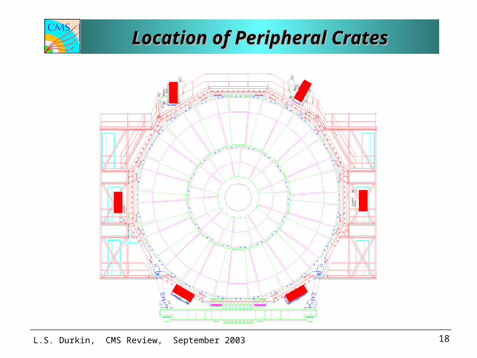
Location of Peripheral CratesLocation of Peripheral CratesLocation of Peripheral CratesLocation of Peripheral Crates
L.S. Durkin, CMS Review, September 2003 19
EMU Peripheral CratesEMU Peripheral CratesEMU Peripheral CratesEMU Peripheral Crates
• Total of 60 crates in EMU– 2 x (12 crates on YE1), serving ME1 station– 2 x (12 crates on YE2), serving ME2,3 stations– 2 x ( 6 crates on YE3), serving ME4 station
• Crate type – 9U VME cage with custom LV power and cooling
• Each crate has a custom backplane in addition to the standard VME backplane
• Power consumption: 175 W per crate– Requires +3.3V, +5V, -12V
• Radiation background (M. Huhtinen)– Per 10 LHC yrs: Neutron fluence 4x1010 cm-2,
Ionization dose 1.3 Gy

L.S. Durkin, CMS Review, September 2003 20
Rack for Peripheral CratesRack for Peripheral CratesRack for Peripheral CratesRack for Peripheral Crates
• Each 600 x 600 rack houses two crates
• LV Power – custom regulator boards feed off AC-DC converters.
• Cooling – plan to use tangential fan with magnetically shielded motor.
• Special strain relief for the input cables designed.
600 600
L.S. Durkin, CMS Review, September 2003 21
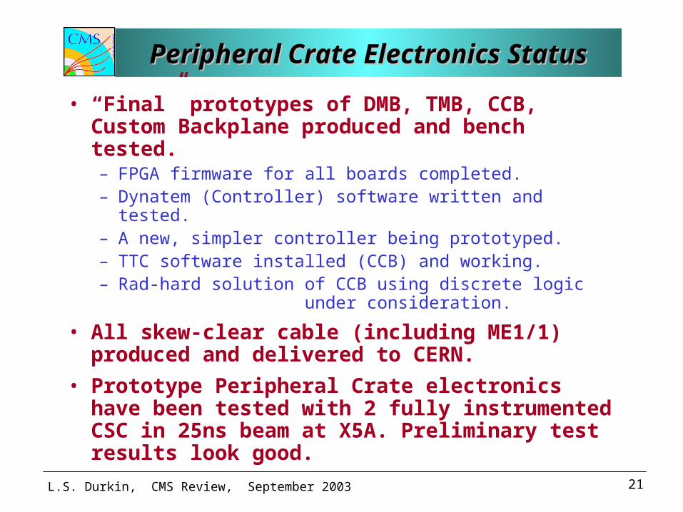
Peripheral Crate Electronics StatusPeripheral Crate Electronics StatusPeripheral Crate Electronics StatusPeripheral Crate Electronics Status
• “Final” prototypes of DMB, TMB, CCB, Custom Backplane produced and bench tested. – FPGA firmware for all boards completed. – Dynatem (Controller) software written and tested.– A new, simpler controller being prototyped.– TTC software installed (CCB) and working.– Rad-hard solution of CCB using discrete logic
under consideration.
• All skew-clear cable (including ME1/1) produced and delivered to CERN.
• Prototype Peripheral Crate electronics have been tested with 2 fully instrumented CSC in 25ns beam at X5A. Preliminary test results look good.
L.S. Durkin, CMS Review, September 2003 22
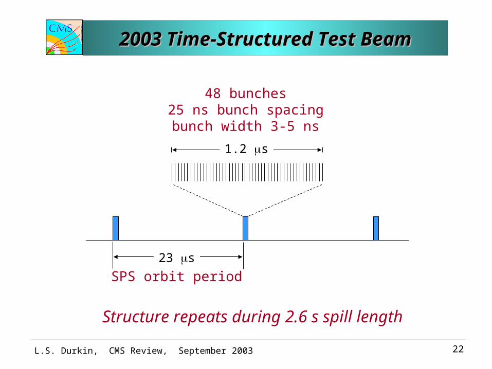
Structure repeats during 2.6 s spill length
48 bunches25 ns bunch spacingbunch width 3-5 ns
SPS orbit period
1.2 s
23 s
2003 Time-Structured Test Beam2003 Time-Structured Test Beam2003 Time-Structured Test Beam2003 Time-Structured Test Beam
L.S. Durkin, CMS Review, September 2003 23
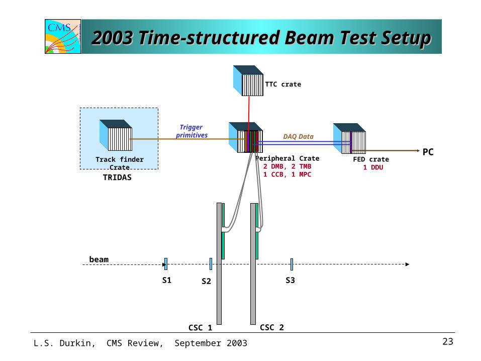
2003 Time-structured Beam Test Setup2003 Time-structured Beam Test Setup2003 Time-structured Beam Test Setup2003 Time-structured Beam Test Setup
Peripheral Crate2 DMB, 2 TMB1 CCB, 1 MPC
FED crate 1 DDU
PC
TTC crate
DAQ Data
Trigger primitives
S1 S2 S3
beam
CSC 1 CSC 2
Track finder Crate
TRIDAS
L.S. Durkin, CMS Review, September 2003 24
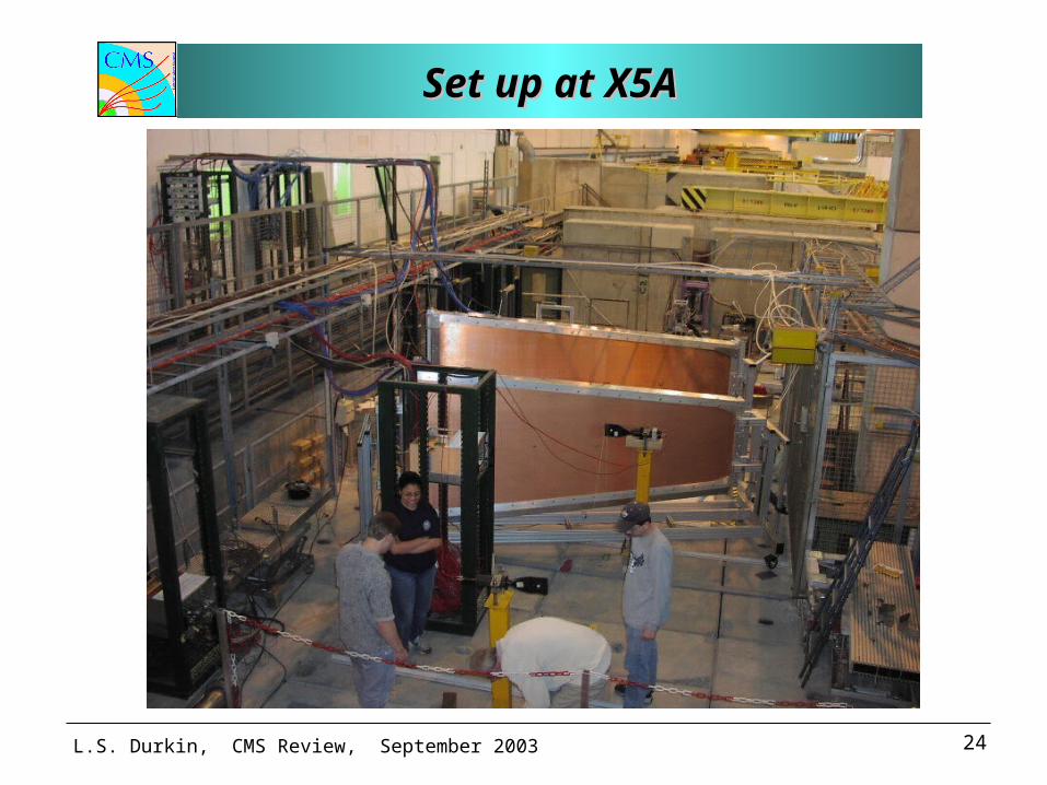
Set up at X5ASet up at X5ASet up at X5ASet up at X5A
L.S. Durkin, CMS Review, September 2003 25
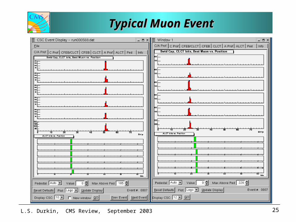
Typical Muon EventTypical Muon EventTypical Muon EventTypical Muon Event
L.S. Durkin, CMS Review, September 2003 26
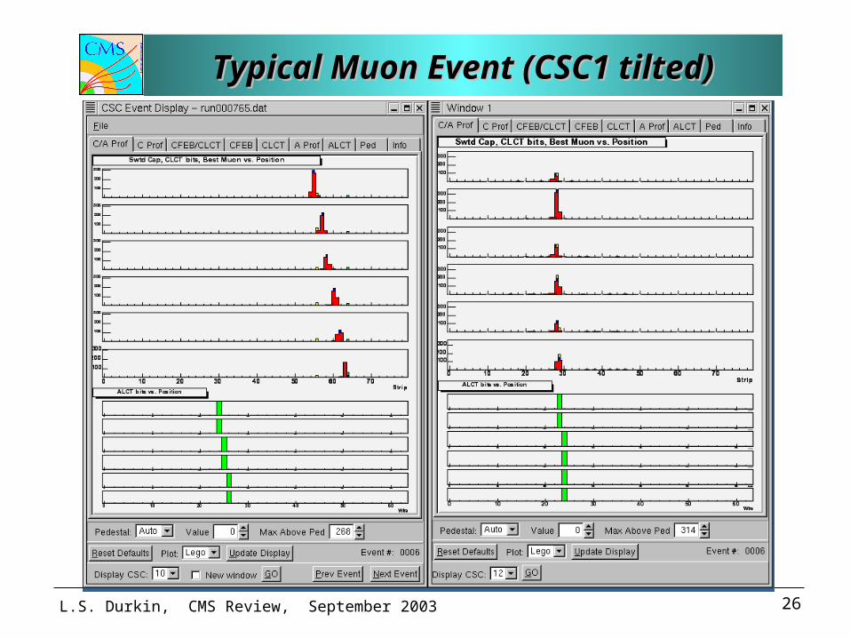
Typical Muon Event (CSC1 tilted)Typical Muon Event (CSC1 tilted)Typical Muon Event (CSC1 tilted)Typical Muon Event (CSC1 tilted)
L.S. Durkin, CMS Review, September 2003 27
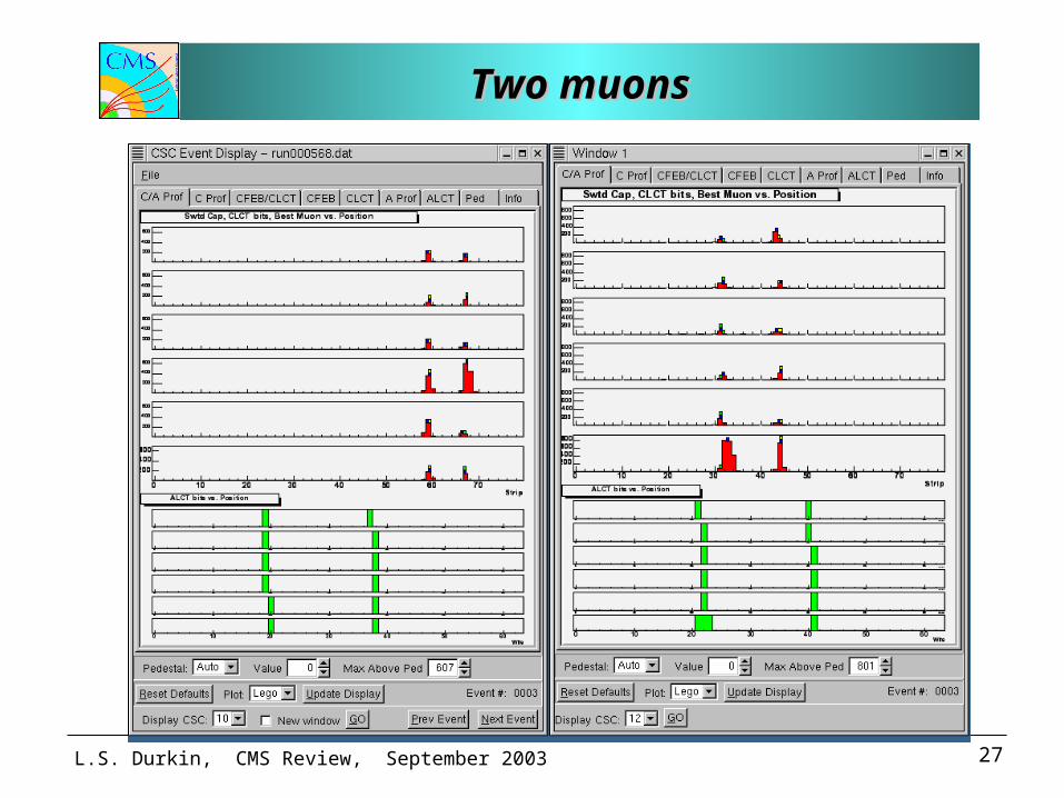
Two muonsTwo muonsTwo muonsTwo muons
L.S. Durkin, CMS Review, September 2003 28
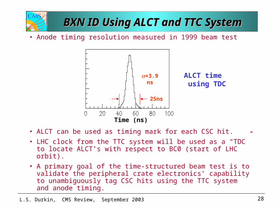
• Anode timing resolution measured in 1999 beam test
• ALCT can be used as timing mark for each CSC hit.
• LHC clock from the TTC system will be used as a “TDC” to locate ALCT’s with respect to BC0 (start of LHC orbit).
• A primary goal of the time-structured beam test is to validate the peripheral crate electronics’ capability to unambiguously tag CSC hits using the TTC system and anode timing.
25ns
=3.9 ns
Time (ns)
ALCT time using TDC
BXN ID Using ALCT and TTC SystemBXN ID Using ALCT and TTC SystemBXN ID Using ALCT and TTC SystemBXN ID Using ALCT and TTC System
L.S. Durkin, CMS Review, September 2003 29
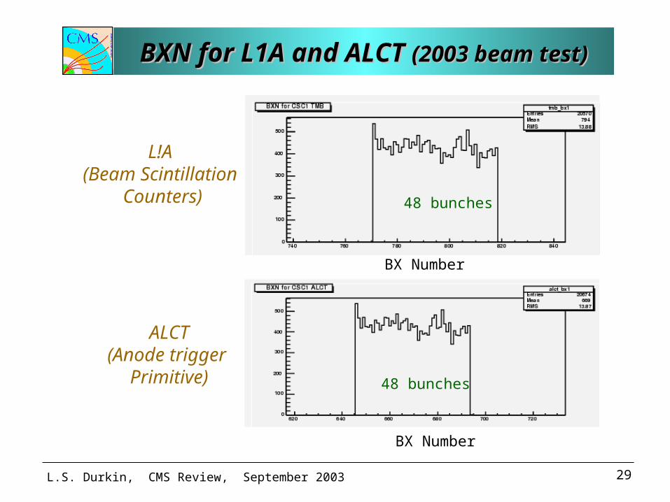
BXN for L1A and ALCT BXN for L1A and ALCT (2003 beam test)(2003 beam test)BXN for L1A and ALCT BXN for L1A and ALCT (2003 beam test)(2003 beam test)
BX Number
L!A (Beam Scintillation
Counters) 48 bunches
BX Number
ALCT(Anode trigger
Primitive) 48 bunches
L.S. Durkin, CMS Review, September 2003 30
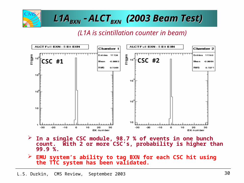
L1AL1ABXNBXN ALCT ALCTBXNBXN (2003 Beam Test) (2003 Beam Test) L1AL1ABXNBXN ALCT ALCTBXNBXN (2003 Beam Test) (2003 Beam Test)
In a single CSC module, 98.7 % of events in one bunch count. With 2 or more CSC’s, probability is higher than 99.9 %.
EMU system’s ability to tag BXN for each CSC hit using the TTC system has been validated.
(L1A is scintillation counter in beam)
CSC #1 CSC #2
L.S. Durkin, CMS Review, September 2003 31
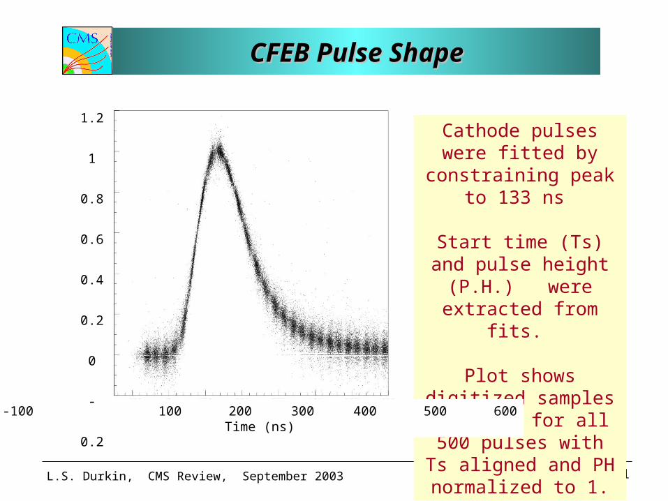
CFEB Pulse ShapeCFEB Pulse ShapeCFEB Pulse ShapeCFEB Pulse Shape
Cathode pulses were fitted by constraining
peak to 133 ns
Start time (Ts) and pulse height (P.H.)
were extracted from fits.
Plot shows digitized samples overlaid for all
500 pulses with Ts aligned and PH normalized to 1.
-100 0 100 200 300 400 500 600Time (ns)
1.2
1
0.8
0.6
0.4
0.2
0
-0.2
L.S. Durkin, CMS Review, September 2003 32
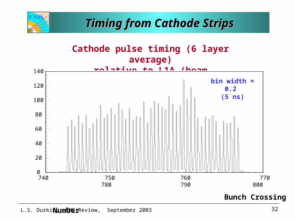
Timing from Cathode StripsTiming from Cathode StripsTiming from Cathode StripsTiming from Cathode Strips
Cathode pulse timing (6 layer average)relative to L1A (beam scintillators)
740 750 760 770 780 790 800
Bunch Crossing Number
bin width = 0.2 (5 ns)
140
120
100
80
60
40
20
0
L.S. Durkin, CMS Review, September 2003 33
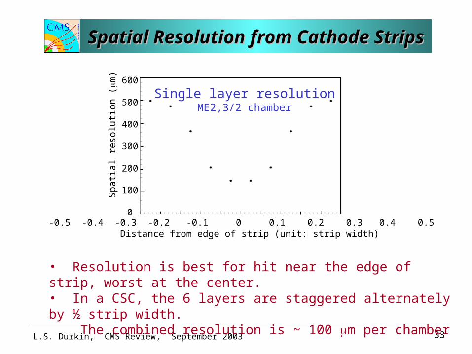
Spatial Resolution from Cathode StripsSpatial Resolution from Cathode StripsSpatial Resolution from Cathode StripsSpatial Resolution from Cathode Strips
• Resolution is best for hit near the edge of strip, worst at the center.• In a CSC, the 6 layers are staggered alternately by ½ strip width. The combined resolution is ~ 100 m per chamber
-0.5 -0.4 -0.3 -0.2 -0.1 0 0.1 0.2 0.3 0.4 0.5 Distance from edge of strip (unit: strip width)
600
500
400
300
200
100
0
Spa
tial
res
olut
ion
(m
) Single layer resolutionME2,3/2 chamber
L.S. Durkin, CMS Review, September 2003 34
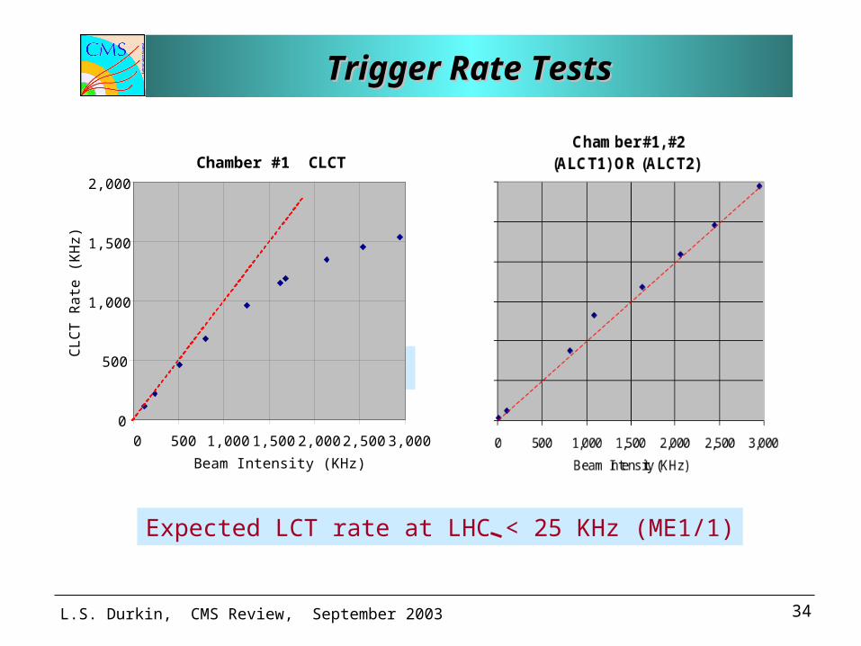
Trigger Rate TestsTrigger Rate TestsTrigger Rate TestsTrigger Rate Tests
Expected LCT rate at LHC < 25 KHz (ME1/1)
data consistent with dead-time = 225 ns
Chamber #1 CLCT
0
500
1,000
1,500
2,000
0 500 1,000 1,500 2,000 2,500 3,000
Beam Intensity (KHz)
CL
CT
Ra
te (
KH
z)
L.S. Durkin, CMS Review, September 2003 35
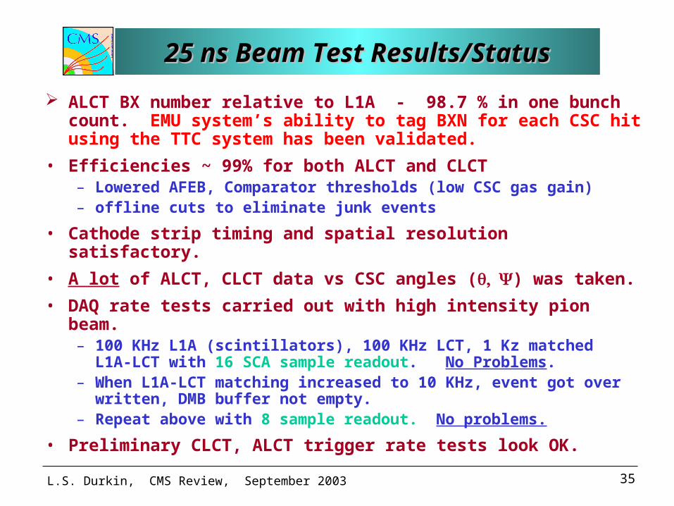
25 ns Beam Test Results/Status25 ns Beam Test Results/Status25 ns Beam Test Results/Status25 ns Beam Test Results/Status
ALCT BX number relative to L1A - 98.7 % in one bunch count. EMU system’s ability to tag BXN for each CSC hit using the TTC system has been validated.
• Efficiencies ~ 99% for both ALCT and CLCT – Lowered AFEB, Comparator thresholds (low CSC gas gain)– offline cuts to eliminate junk events
• Cathode strip timing and spatial resolution satisfactory.
• A lot of ALCT, CLCT data vs CSC angles () was taken.
• DAQ rate tests carried out with high intensity pion beam.– 100 KHz L1A (scintillators), 100 KHz LCT, 1 Kz matched L1A-LCT
with 16 SCA sample readout. No Problems.– When L1A-LCT matching increased to 10 KHz, event got over
written, DMB buffer not empty. – Repeat above with 8 sample readout. No problems.
• Preliminary CLCT, ALCT trigger rate tests look OK.
L.S. Durkin, CMS Review, September 2003 36
Electronics ControlElectronics ControlElectronics ControlElectronics Control
• Fast Control– Reload FPGA’s to recover from SEU
– Reset buffers to restore synchronization
– Resets will come from TTCrx via the Clock Control Board
• Slow Control (part of DCS)– Download FPGA firmware
– Down load thresholds
– Download calibration constants
– Debug electronics
– Monitor LV voltages, currents
– Monitor board temperatures.
L.S. Durkin, CMS Review, September 2003 37
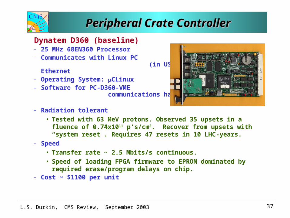
Peripheral Crate ControllerPeripheral Crate ControllerPeripheral Crate ControllerPeripheral Crate Controller
Dynatem D360 (baseline)– 25 MHz 68EN360 Processor– Communicates with Linux PC
(in USC55) via 10 Base FL Ethernet– Operating System: CLinux – Software for PC-D360-VME
communications have been written and tested.
– Radiation tolerant
• Tested with 63 MeV protons. Observed 35 upsets in a fluence of 0.74x10¹¹ p’s/cm2. Recover from upsets with “system reset”. Requires 47 resets in 10 LHC-years.
– Speed
• Transfer rate ~ 2.5 Mbits/s continuous.
• Speed of loading FPGA firmware to EPROM dominated by required erase/program delays on chip.
– Cost ~ $1100 per unit
L.S. Durkin, CMS Review, September 2003 38
A New Crate Controller in DevelopmentA New Crate Controller in DevelopmentA New Crate Controller in DevelopmentA New Crate Controller in Development
• A simple custom board containing – XILINX Virtex-II Pro with built in Gigabit Ethernet– Optical transceiver (for Gigabit Ethernet)
• Advantages– A much simpler crate controller
– Communicates with stand-alone PC (in USC55) via ethernet
– Gigabit ethernet PCI card commercially available
– All programming done on PC. No controller specific software.
– Fast: transfer rate ~ 1 Mbits/s
– Inexpensive: ~ $600 per unit
• Status of development (at Ohio State Univ)– XILINX II Pro now available
– Firmware for Gigabit ethernet already exits.
– Firmware for a limited VME master to be developed.
L.S. Durkin, CMS Review, September 2003 39
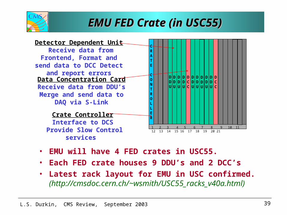
EMU FED Crate (in USC55) EMU FED Crate (in USC55) EMU FED Crate (in USC55) EMU FED Crate (in USC55)
CRATE
CONTROLLER
DDU
DCC
DDU
DDU
DDU
DDU
DDU
DDU
DCC
DDU
DDU
1 2 3 4 5 6 7 8 9 10 11 12 13 14 15 16 17 18 19 20 21
Crate Controller Interface to DCS
Provide Slow Control services
Detector Dependent Unit Receive data from Frontend, Format and send data to DCC
Detect and report errors
Data Concentration Card Receive data from DDU’s
Merge and send data to DAQ via S-Link
• EMU will have 4 FED crates in USC55. • Each FED crate houses 9 DDU’s and 2 DCC’s • Latest rack layout for EMU in USC confirmed.
(http://cmsdoc.cern.ch/~wsmith/USC55_racks_v40a.html)
L.S. Durkin, CMS Review, September 2003 40
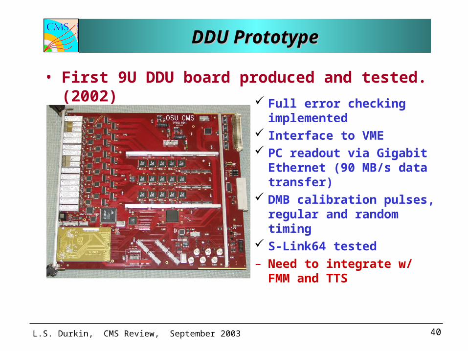
DDU PrototypeDDU PrototypeDDU PrototypeDDU Prototype
• First 9U DDU board produced and tested. (2002)
Full error checking implemented
Interface to VME PC readout via Gigabit
Ethernet (90 MB/s data transfer)
DMB calibration pulses, regular and random timing
S-Link64 tested– Need to integrate w/ FMM
and TTS
L.S. Durkin, CMS Review, September 2003 41
Looking AheadLooking AheadLooking AheadLooking Ahead
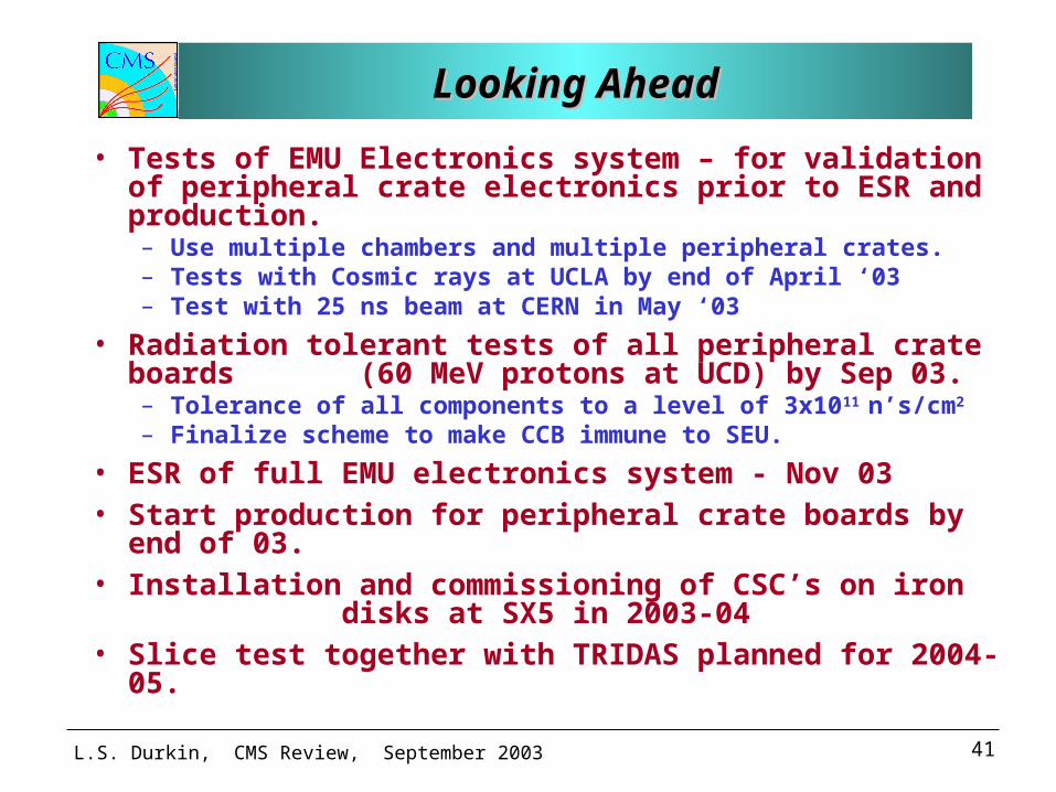
• Tests of EMU Electronics system – for validation of peripheral crate electronics prior to ESR and production.– Use multiple chambers and multiple peripheral crates.– Tests with Cosmic rays at UCLA by end of April ‘03– Test with 25 ns beam at CERN in May ‘03
• Radiation tolerant tests of all peripheral crate boards (60 MeV protons at UCD) by Sep 03.– Tolerance of all components to a level of 3x10¹¹ n’s/cm2
– Finalize scheme to make CCB immune to SEU.
• ESR of full EMU electronics system - Nov 03• Start production for peripheral crate boards by end of
03. • Installation and commissioning of CSC’s on iron
disks at SX5 in 2003-04 • Slice test together with TRIDAS planned for 2004-05.
L.S. Durkin, CMS Review, September 2003 42
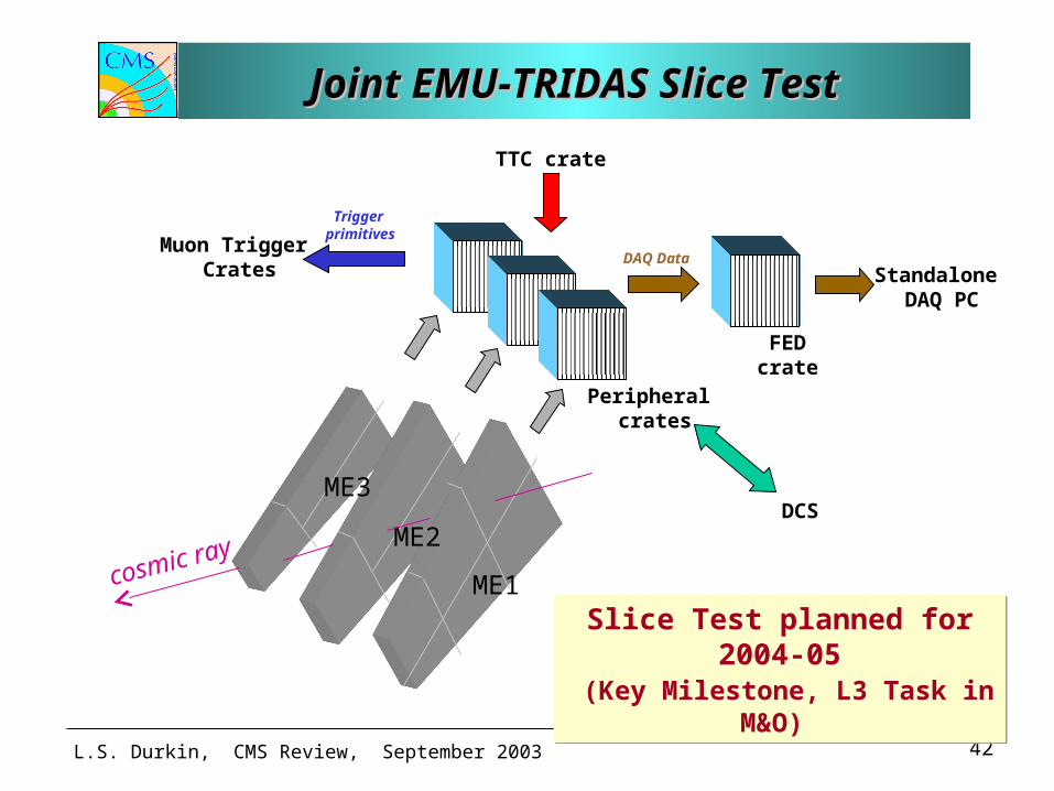
Joint EMU-TRIDAS Slice TestJoint EMU-TRIDAS Slice TestJoint EMU-TRIDAS Slice TestJoint EMU-TRIDAS Slice Test
Peripheral crates
FEDcrate
Standalone DAQ PC
Muon Trigger Crates
DCS
ME1
ME2
ME3
TTC crate
Slice Test planned for 2004-05 (Key Milestone, L3 Task in M&O) Slice Test planned for 2004-05 (Key Milestone, L3 Task in M&O)
cosmic ray
DAQ Data
Trigger primitives
L.S. Durkin, CMS Review, September 2003 43
SummarySummarySummarySummary
• On-chamber boards met performance requirements and passed extensive radiation, magnetic field and sparking tests.
• Production of on-chamber boards is on schedule and within budget.
• Prototype work of all off-chamber boards (in peripheral crates and in FED crates) are in advanced stages.
• Integrated EMU electronics system works well and tested successfully in 25 ns time-structured beam at CERN (May23 – June1, 2003).
• Production review of Peripheral crate electronics in Nov 2003. Production scheduled to start in 2004.
• EMU Electronics is in good shape.


![Welcome [] · 4. www. emu .edu.tr. Welcome. 1.2 MISSION AND VISION. Eastern Mediterranean University aims to offer . contemporary, sustainable and quality education at](https://static.fdocuments.in/doc/165x107/5adb714f7f8b9a4a268b4e1f/welcome-www-emu-edutr-welcome-12-mission-and-vision-eastern-mediterranean.jpg)


![Optical Sensors [2010] :Product Catalog - Digi-Key Sheets/Rohm PDFs/Optical Sensors...Product Catalog 2010 Optical Sensors Opto Electronics. ... SMD Type RPI-0125 1.2 1.2 1.2 2.0 ...](https://static.fdocuments.in/doc/165x107/5b047d6a7f8b9aba168d60e2/optical-sensors-2010-product-catalog-digi-key-sheetsrohm-pdfsoptical-sensorsproduct.jpg)