12....241 ANGLE GUIDE PINS Part No. d1 x l d2 l1 k EOC1040 10 x 40 12 4 3 EOC1060 10 x 60 12 4 3...
20
230 Moulding Supplies Edition 10 // www.mouldpro.com 12. MOULD COMPONENTS 231 12.1 EJECTOR PINS 236 12.2 SLEEVE EJECTORS 237 12.3 FLAT EJECTORS 238 12.4 CORE PINS 239 12.5 DOWEL PINS 241 12.6 ANGLE GUIDE PINS 242 12.7 SOCKET HEAD CAP SCREWS 243 12.8 SHOULDER SCREWS 244 12.9 SPRING PLUNGERS 245 12.10 ISO SPRINGS 248 12.11 MOULD CYCLE COUNTER
Transcript of 12....241 ANGLE GUIDE PINS Part No. d1 x l d2 l1 k EOC1040 10 x 40 12 4 3 EOC1060 10 x 60 12 4 3...
230 Moulding Supplies Edition 10 // www.mouldpro.com
12.MOULD COMPONENTS
231 12.1 EJECTOR PINS 236 12.2
SLEEVE EJECTORS 237 12.3 FLAT EJECTORS
238 12.4 CORE PINS 239 12.5
DOWEL PINS 241 12.6 ANGLE GUIDE PINS
242 12.7 SOCKET HEAD CAP SCREWS 243 12.8
SHOULDER SCREWS 244 12.9 SPRING PLUNGERS
245 12.10 ISO SPRINGS 248 12.11 MOULD CYCLE
COUNTER
231
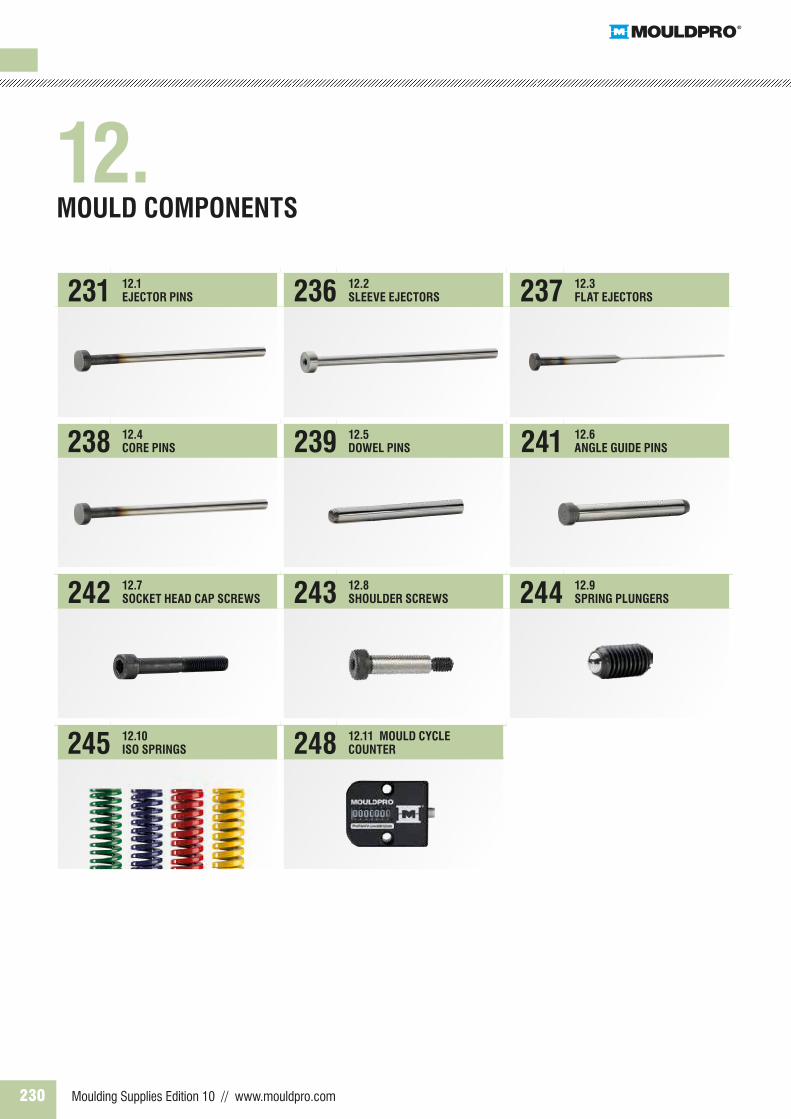
EJECTOR PINS, DIN 1530, TYPE AH - HARDENED
L 0/+2d1 g6 d2 0 -0,2 k 0 -0,05 R +0,2 0 d3 100 125 160 200 250 315 400
1,5 3 1,5 0,2 d1 + 0,03 • • • •1,6 • • • •2,0 4 2 • • • • • •2,2 • • • • • •2,5 5 0,3 • • • • • •2,7 • • • • • •3,0 6 3 • • • • • • •3,2 • • • • • •3,5 7 • • • • • •3,7 • • • • • •4,0 8 • • • • • • •4,2 • • • • • • •4,5 • • • • • • •4,7 • • • • • • •5,0 10 • • • • • • •5,2 • • • • • • •5,5 • • • • • • •6,0 12 5 0,5 • • • • • • •6,2 • • • • • • •6,5 • • • • • • •7,0 • • • • • • •8,0 14 • • • • • • •8,2 d1 + 0,04 • • • • • • •8,5 • • • • • • •9,0 • • • • • • •
10,0 • • • • • • •10,2 • • • • • • •10,5 • • • • • • •11,0 • • • • • • •12,0 20 7 0,8 • • • • • • •12,2 • • • • • • •12,5 • • • • • • •14,0 22 • • • • • • •16,0 • • • • • • •18,0 24 d1 + 0,07 • • • • • • •20,0 26 8 1,0 • • • • • • •
DescriptionSurface: Hardened and PolishedMaterial: 1.2516Hardness: 60 ± 2 HRC. Head 45 ± 5 HRC.
Order exampleUDSAH+d1+L ex. UDSAH4160 (4x160 mm)
EJECTOR PINS
232 Moulding Supplies Edition 10 // www.mouldpro.com
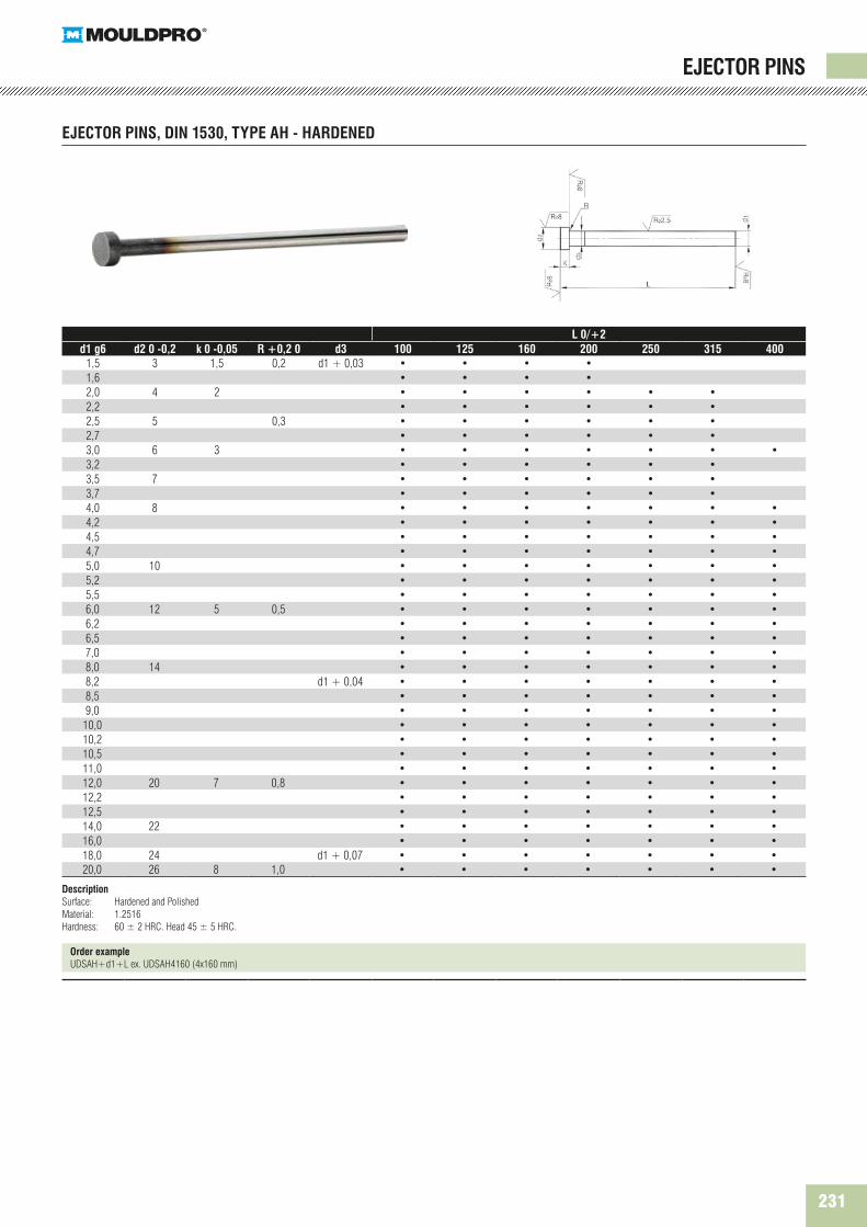
L 0/+2d1 g6 d2 -0,2 k -0,05 R d3 100 125 160 200 250 315 400 500 630 800 1000
1,5 3 1,5 0,2 d1 + 0,03 • • • •2,0 4 2 • • • • •2,2 0,3 • • • • •2,5 5 3 • • • • • •3,0 6 • • • • • • • •3,2 • • • • • • •3,5 7 • • • • • • • •3,7 • • • • • •4,0 8 • • • • • • • •4,2 • • • • • • •4,5 • • • • • • •5,0 10 • • • • • • • • • •5,2 • • • • • • • •6,0 12 5 0,5 • • • • • • • • • •6,2 • • • • • • • •8,0 14 • • • • • • • • • • •8,2 d1 + 0,04 • • • • • • • •10,0 16 • • • • • • • • • • •10,2 • • • • • • • •11,0 • • • • • • • •12,0 20 7 0,8 • • • • • • • • • • •12,2 • • • • • • • • •12,5 • • • • • • • • •14,0 22 • • • • • • • • • • •16,0 • • • • • • • • • • •20,0 26 8 1 d1 + 0,1 • • • • • • • • • •25,0 32 10 • • • • • • • • •32,0 40 • • • • • • • • •
DescriptionSurface: Nitrided and PolishedMaterial: 1.2344Hardness: 65 ± 2 HRC. Head 45 ± 5 HRC.
Order exampleUDSAB+d1+L ex. UDSAB4160 (4x160 mm)
EJECTOR PINS
EJECTOR PINS, DIN 6751, TYPE AB - NITRIDED
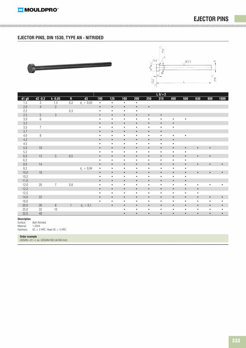
233
L 0/+2d1 g6 d2 -0,2 k -0,05 R d3 100 125 160 200 250 315 400 500 630 800 1000
1,5 3 1,5 0,2 d1 + 0,03 • • • •2,0 4 2 • • • • •2,2 0,3 • • • •2,5 5 3 • • • • • •3,0 6 • • • • • • • •3,2 • • • • • • •3,5 7 • • • • • • •3,7 • • • • • •4,0 8 • • • • • • • •4,2 • • • • • • •4,5 • • • • • • •5,0 10 • • • • • • • • • •5,2 • • • • • • • •6,0 12 5 0,5 • • • • • • • • • •6,2 • • • • • • • •8,0 14 • • • • • • • • • • •8,2 d1 + 0,04 • • • • • • • •10,0 16 • • • • • • • • • • •10,2 • • • • • • • •11,0 • • • • • • • •12,0 20 7 0,8 • • • • • • • • • • •12,2 • • • • • • • • •12,5 • • • • • • • • •14,0 22 • • • • • • • • • • •16,0 • • • • • • • • • • •20,0 26 8 1 d1 + 0,1 • • • • • • • • • •25,0 32 10 • • • • • • • • •32,0 40 • • • • • • • • •
DescriptionSurface: Bath NitridedMaterial: 1.2344Hardness: 65 ± 2 HRC. Head 45 ± 5 HRC.
Order exampleUDSAN+d1+L ex. UDSAN4160 (4x160 mm)
EJECTOR PINS
EJECTOR PINS, DIN 1530, TYPE AN - NITRIDED

234 Moulding Supplies Edition 10 // www.mouldpro.com
L 0/+2d1 g6 d2-0,2 k -0,05 R 0/+0,2 d3 100 125 160 200 250
1 1,8 0,3 0,3 d1 + 0,03 • • • • •1,2 2 • • • • •1,5 2,2 • • • • •2 3 • • • • •
2,2 3,2 • • • • •2,5 3,5 • • • • •3 4,5 • • • • •
3,5 5 • • • • •4 5,5 • • • • •
4,5 6 • • • • •5 6,5 • • • • •
5,5 7 0,5 • • • • •6 8 0,5 • • • • •
6,5 9 • • • • •7 • • • • •
7,5 10 • • • • •8 • • • • •
10 12 • • • • •12 14 • • • • •14 16 0,8 0,8 d1 + 0,04 • • • • •16 18 • • • • •
DescriptionSurface: Hardened and PolishedMaterial: 1.2516Hardness: 60 ± 2 HRC. Head 45 ± 5 HRC.
Order exampleUDSD+d1+L ex. UDSD4160 (4x160 mm)
EJECTOR PINS
EJECTOR PINS, DIN 1530, TYPE D - HARDENED

235
EJECTOR PINS
EJECTOR PINS, DIN 1530, TYPE CH - HARDENED
L1 100 125 160 200 250d1 g6 d2 0-0,2 d3 g6 k 0-0,05 R -0,05 L2 50 50 75 75 75
0,8 4 2 2 0,2 • • • • •0,9 4 2 2 0,2 • • • • •1,0 4 2 2 0,2 • • • • •1,1 4 2 2 0,2 • • • • •1,2 4 2 2 0,2 • • • • •1,3 4 2 2 0,2 • • • • •1,4 4 2 2 0,2 • • • • •1,5 6 3 3 0,3 • • • • •1,6 6 3 3 0,3 • • • • •1,7 6 3 3 0,3 • • • • •1,8 6 3 3 0,3 • • • • •1,9 6 3 3 0,3 • • • • •2,0 6 3 3 0,3 • • • • •2,1 6 3 3 0,3 • • • • •2,2 6 3 3 0,3 • • • • •2,3 6 3 3 0,3 • • • • •2,4 6 3 3 0,3 • • • • •2,5 6 3 3 0,3 • • • • •
DescriptionSurface: Hardened and PolishedMaterial: 1.2516Hardness: 60 ± 2 HRC. Head 45 ± 5 HRC.
Order exampleUDSCH+d1+L ex. UDSCH2160 (2x160 mm)
236 Moulding Supplies Edition 10 // www.mouldpro.com
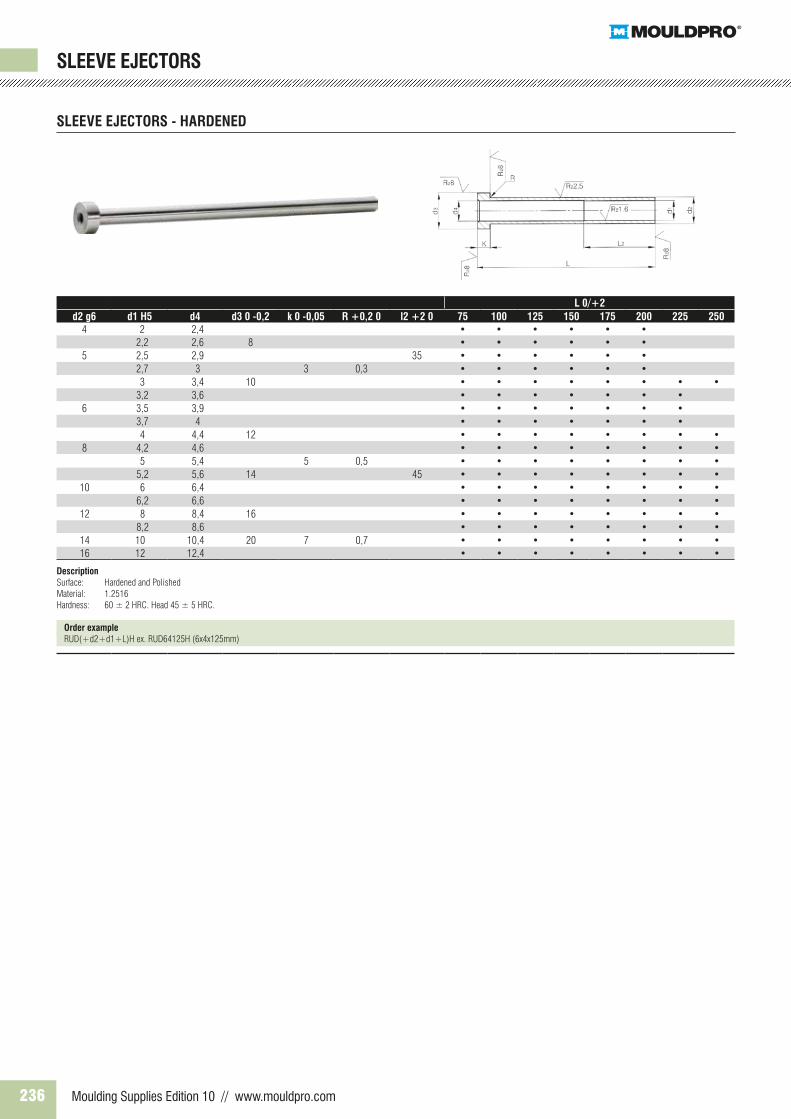
L 0/+2d2 g6 d1 H5 d4 d3 0 -0,2 k 0 -0,05 R +0,2 0 l2 +2 0 75 100 125 150 175 200 225 250
4 2 2,4 • • • • • • 2,2 2,6 8 • • • • • •
5 2,5 2,9 35 • • • • • • 2,7 3 3 0,3 • • • • • • 3 3,4 10 • • • • • • • •
3,2 3,6 • • • • • • •6 3,5 3,9 • • • • • • •
3,7 4 • • • • • • • 4 4,4 12 • • • • • • • •
8 4,2 4,6 • • • • • • • • 5 5,4 5 0,5 • • • • • • • •
5,2 5,6 14 45 • • • • • • • •10 6 6,4 • • • • • • • •
6,2 6,6 • • • • • • • •12 8 8,4 16 • • • • • • • •
8,2 8,6 • • • • • • • •14 10 10,4 20 7 0,7 • • • • • • • •16 12 12,4 • • • • • • • •
DescriptionSurface: Hardened and PolishedMaterial: 1.2516Hardness: 60 ± 2 HRC. Head 45 ± 5 HRC.
Order exampleRUD(+d2+d1+L)H ex. RUD64125H (6x4x125mm)
SLEEVE EJECTORS
SLEEVE EJECTORS - HARDENED
237
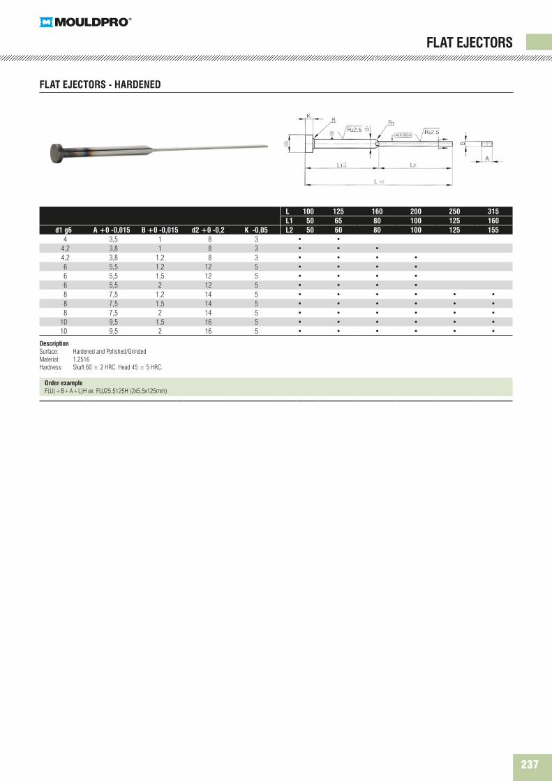
L 100 125 160 200 250 315L1 50 65 80 100 125 160
d1 g6 A +0 -0,015 B +0 -0,015 d2 +0 -0,2 K -0,05 L2 50 60 80 100 125 155 4 3,5 1 8 3 • •
4,2 3,8 1 8 3 • • • 4,2 3,8 1,2 8 3 • • • • 6 5,5 1,2 12 5 • • • • 6 5,5 1,5 12 5 • • • • 6 5,5 2 12 5 • • • • 8 7,5 1,2 14 5 • • • • • • 8 7,5 1,5 14 5 • • • • • • 8 7,5 2 14 5 • • • • • •10 9,5 1,5 16 5 • • • • • •10 9,5 2 16 5 • • • • • •
DescriptionSurface: Hardened and Polished/GrindedMaterial: 1.2516Hardness: Skaft 60 ± 2 HRC. Head 45 ± 5 HRC.
Order exampleFLU(+B+A+L)H ex. FLU25,5125H (2x5,5x125mm)
FLAT EJECTORS
FLAT EJECTORS - HARDENED

238 Moulding Supplies Edition 10 // www.mouldpro.com
d1 g6 d2-0,2 k-0,05 R d3 100 125 160 200 250 3152 4 2 0,2 d1 + 0,03 • • • •
2,2 0,3 • • •2,5 5 3 • • •3 6 • • • •
3,2 • • • •3,5 7 • • • •4 8 • • • •
4,2 • • • •4,5 • • • •5 10 • • • • •
5,2 • • • •5,5 • • • •6 12 5 0,5 • • • • •
6,2 • • • • •6,5 • • • • •7 • • • • •8 14 • • • • • •
10 d1 + 0,04 • • • • • •12 20 7 • • • • •16 • • • • • •
DescriptionSurface: Nitrided and PolishedMaterial: 1.2344Hardness: 40 ± 2 HRC. Head 45 ± 5 HRC
Order exampleUDSAC+d1+L ex. UDSAC4160 (4X160 mm)
CORE PINS ISO 6751 NON HARDENED (SOFT)
CORE PINS

239
L d 2 3 4 5 6 8 10 12 14 16 206 • •8 • • • •10 • • • • •12 • • • • •14 • • • • •16 • • • • • • •18 • • • • • • •20 • • • • • • • •24 • • • • • • • • •28 • • • • • • • • •32 • • • • • • • • • •36 • • • • • • • • •40 • • • • • • • • •45 • • • • • • • • •50 • • • • • • • • •55 • • • • • • • • •60 • • • • • • • • •70 • • • • • • • •80 • • • • • • • •90 • • • • • • •100 • • • • • • •120 • • • • • •130 • •140 • •150 • •
DescriptionSurface: Hardened and PolishedMaterial: 1.3505Tolerance: m6Hardness: 60 ± 2 HRC.
Order exampleCYL+d+L ex. CYL532 (5x32mm)
DOWEL PINS
DOWEL PINS, DIN 6325

240 Moulding Supplies Edition 10 // www.mouldpro.com
DOWEL PINS - THREADED - DIN 7979
L1 10 12 16 16 20 20 25L d Ø 6 M4 Ø 8 M5 Ø 10 M6 Ø 12 M6 Ø 14 M8 Ø 16 M8 Ø 20 M10
16 • •18 • •20 • • • • 24 • • • • 28 • • • • •32 • • • • • •36 • • • • • •40 • • • • • • •45 • • • • • • •50 • • • • • • •55 • • • • • • •60 • • • • • • •70 • • • • • • •80 • • • • • • •90 • • • • • • •100 • • • • • • •110 • • • • • •120 • • • • • •
DescriptionSurface: Hardened and PolishedMaterial: 1.3505Tolerance: m6Hardness: 60 ± 2 HRC.
Order exampleCYLG+d+L ex. CYLG832 (8x32mm)
DOWEL PINS
241
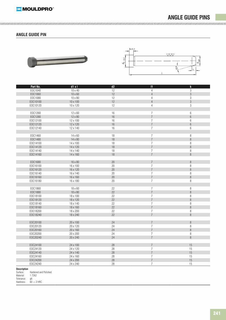
ANGLE GUIDE PINS
Part No. d1 x l d2 l1 kEOC1040 10 x 40 12 4 3EOC1060 10 x 60 12 4 3EOC1080 10 x 80 12 4 3
EOC10100 10 x 100 12 4 3EOC10120 10 x 120 12 4 3
EOC1260 12 x 60 16 7 6EOC1280 12 x 80 16 7 6
EOC12100 12 x 100 16 7 6EOC12120 12 x 120 16 7 6EOC12140 12 x 140 16 7 6
EOC1460 14 x 60 18 7 8EOC1480 14 x 80 18 7 8
EOC14100 14 x 100 18 7 8EOC14120 14 x 120 18 7 8EOC14140 14 x 140 18 7 8EOC14160 14 x 160 18 7 8
EOC1680 16 x 80 20 7 8EOC16100 16 x 100 20 7 8EOC16120 16 x 120 20 7 8EOC16140 16 x 140 20 7 8EOC16160 16 x 160 20 7 8EOC16180 16 x 180 20 7 8
EOC1860 18 x 60 22 7 8EOC1880 18 x 80 22 7 8
EOC18100 18 x 100 22 7 8EOC18120 18 x 120 22 7 8EOC18140 18 x 140 22 7 8EOC18160 18 x 160 22 7 8EOC18200 18 x 200 22 7 8EOC18240 18 x 240 22 7 8
EOC20100 20 x 100 24 7 8EOC20120 20 x 120 24 7 8EOC20160 20 x 160 24 7 8EOC20200 20 x 200 24 7 8EOC20240 20 x 240 24 7 8
EOC24100 24 x 100 28 7 15EOC24120 24 x 120 28 7 15EOC24140 24 x 140 28 7 15EOC24160 24 x 160 28 7 15EOC24200 24 x 200 28 7 15EOC24240 24 x 240 28 7 15
DescriptionSurface: Hardened and PolishedMaterial: 1.7262Tolerance: g6Hardness: 60 ± 2 HRC
ANGLE GUIDE PIN
242 Moulding Supplies Edition 10 // www.mouldpro.com
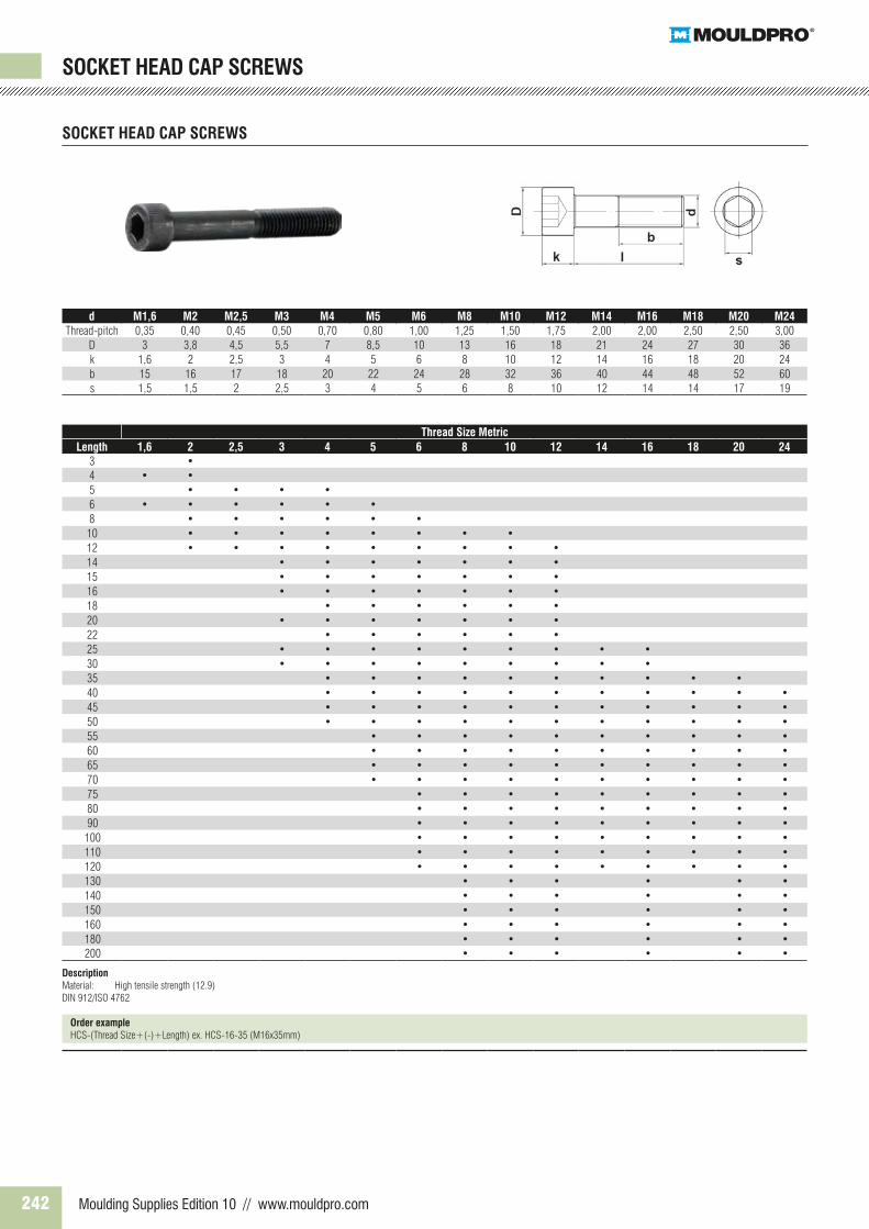
SOCKET HEAD CAP SCREWS
Thread Size MetricLength 1,6 2 2,5 3 4 5 6 8 10 12 14 16 18 20 24
3 •4 • •5 • • • •6 • • • • • •8 • • • • • •10 • • • • • • • •12 • • • • • • • • •14 • • • • • • •15 • • • • • • •16 • • • • • • •18 • • • • • •20 • • • • • • •22 • • • • • •25 • • • • • • • • •30 • • • • • • • • •35 • • • • • • • • • •40 • • • • • • • • • • •45 • • • • • • • • • • •50 • • • • • • • • • • •55 • • • • • • • • • •60 • • • • • • • • • •65 • • • • • • • • • •70 • • • • • • • • • •75 • • • • • • • • •80 • • • • • • • • •90 • • • • • • • • •100 • • • • • • • • •110 • • • • • • • • •120 • • • • • • • • •130 • • • • • •140 • • • • • •150 • • • • • •160 • • • • • •180 • • • • • •200 • • • • • •
DescriptionMaterial: High tensile strength (12.9)DIN 912/ISO 4762
Order exampleHCS-(Thread Size+(-)+Length) ex. HCS-16-35 (M16x35mm)
SOCKET HEAD CAP SCREWS
d M1,6 M2 M2,5 M3 M4 M5 M6 M8 M10 M12 M14 M16 M18 M20 M24Thread-pitch 0,35 0,40 0,45 0,50 0,70 0,80 1,00 1,25 1,50 1,75 2,00 2,00 2,50 2,50 3,00
D 3 3,8 4,5 5,5 7 8,5 10 13 16 18 21 24 27 30 36k 1,6 2 2,5 3 4 5 6 8 10 12 14 16 18 20 24b 15 16 17 18 20 22 24 28 32 36 40 44 48 52 60s 1,5 1,5 2 2,5 3 4 5 6 8 10 12 14 14 17 19

243
SHOULDER SCREWS, ISO 7379
SHOULDER SCREWS
d2h8 6 8 10 12 16 20 24d1 5 X 0,8 6 X 1 8 X 1,25 10 X 1,5 12 X 1,75 16 X 2 20 X 2,5d3 10 13 16 18 24 30 36K 4,5 5,5 7 8 10 14 16L2 9,5 11 13 16 18 22 27S 3 4 5 6 8 10 12
Kg/mm 0,68 1,15 3 6 11 28 55
L1 L1 h1110 • 12 • • 16 • • • 20 • • • • 25 • • • • 30 • • • • • 35 • • • • • 40 • • • • • • 45 • • • • • • 50 • • • • • • • 55 • • • • • • 60 • • • • • • 65 • • • • • • 70 • • • • • • 80 • • • • • 90 • • • •
100 • • • • 120 • • • •
DescriptionMaterial: High tensile strength (12.9)ISO 7379
Order exampleUNBH+d2+L1 ex. UNBH610 (6 x 10 mm)
244 Moulding Supplies Edition 10 // www.mouldpro.com
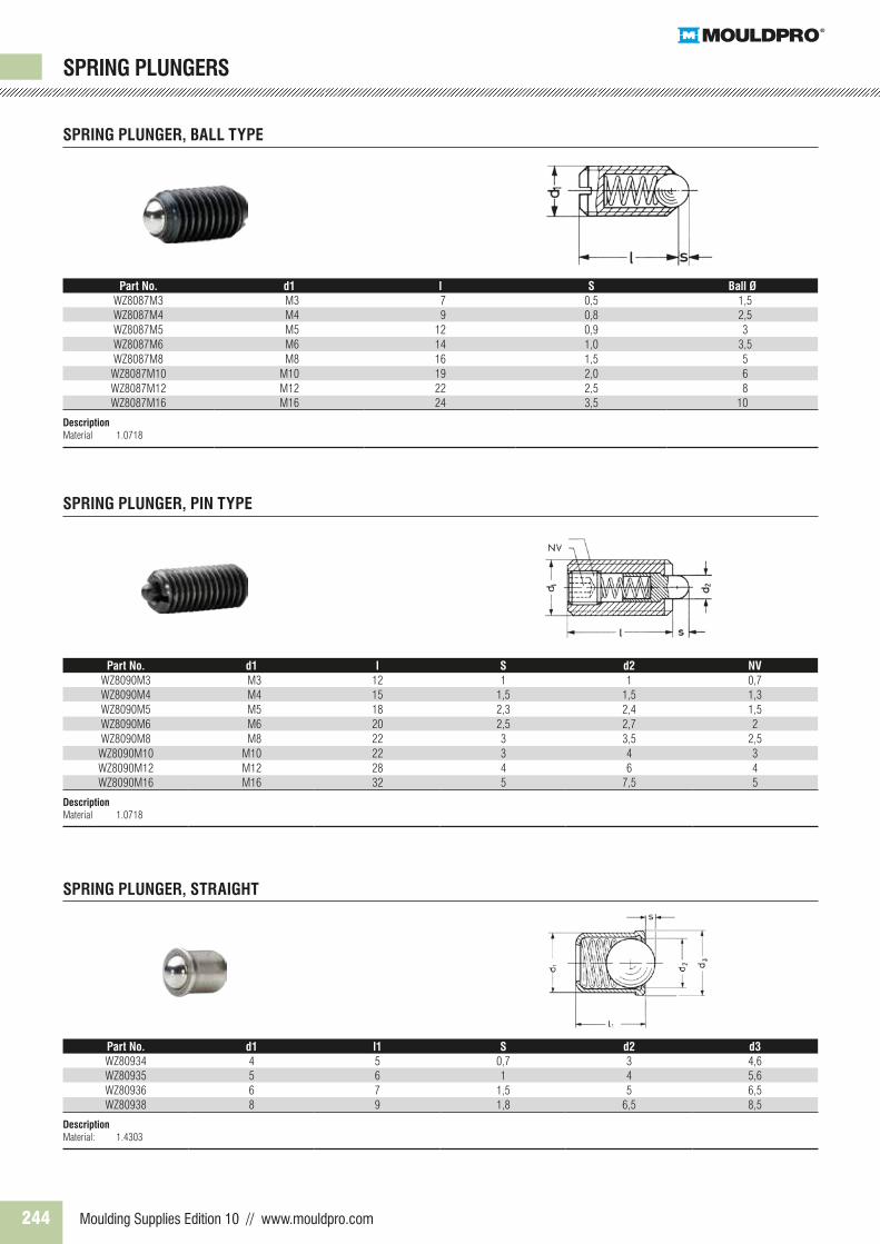
Part No. d1 l S Ball ØWZ8087M3 M3 7 0,5 1,5WZ8087M4 M4 9 0,8 2,5WZ8087M5 M5 12 0,9 3WZ8087M6 M6 14 1,0 3,5WZ8087M8 M8 16 1,5 5WZ8087M10 M10 19 2,0 6WZ8087M12 M12 22 2,5 8WZ8087M16 M16 24 3,5 10
DescriptionMaterial 1.0718
Part No. d1 l S d2 NVWZ8090M3 M3 12 1 1 0,7WZ8090M4 M4 15 1,5 1,5 1,3WZ8090M5 M5 18 2,3 2,4 1,5WZ8090M6 M6 20 2,5 2,7 2WZ8090M8 M8 22 3 3,5 2,5WZ8090M10 M10 22 3 4 3WZ8090M12 M12 28 4 6 4WZ8090M16 M16 32 5 7,5 5
DescriptionMaterial 1.0718
Part No. d1 l1 S d2 d3WZ80934 4 5 0,7 3 4,6WZ80935 5 6 1 4 5,6WZ80936 6 7 1,5 5 6,5WZ80938 8 9 1,8 6,5 8,5
DescriptionMaterial: 1.4303
SPRING PLUNGER, BALL TYPE
SPRING PLUNGER, PIN TYPE
SPRING PLUNGER, STRAIGHT
SPRING PLUNGERS

245
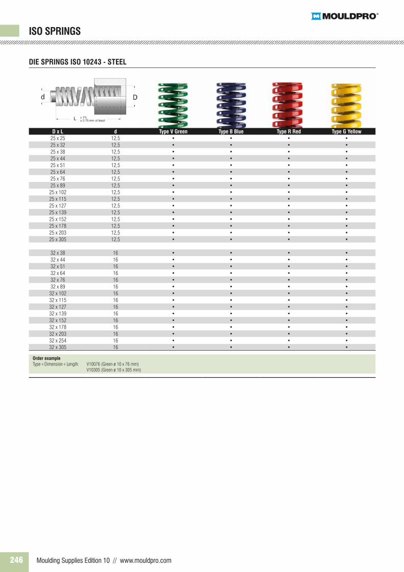
ISO SPRINGS
DIE SPRINGS ISO 10243 - STEEL
D x L d Type V Green Type B Blue Type R Red Type G Yellow10 x 38 5 • • • •10 x 44 5 • • • •10 x 51 5 • • • •10 x 64 5 • • • •10 x 76 5 • • • •10 x 305 5 • • • •
13 x 25 6,3 • • • •13 x 32 6,3 • • • •13 x 38 6,3 • • • •13 x 44 6,3 • • • •13 x 51 6,3 • • • •13 x 64 6,3 • • • •13 x 76 6,3 • • • •13 x 89 6,3 • • • •13 x 102 6,3 • • • •13 x 305 6,3 • • • •
16 x 25 8 • • • •16 x 32 8 • • • •16 x 38 8 • • • •16 x 44 8 • • • •16 x 51 8 • • • •16 x 64 8 • • • •16 x 76 8 • • • •16 x 89 8 • • • •16 x 102 8 • • • •16 x 115 8 • • • •16 x 305 8 • • • •
20 x 25 10 • • • •20 x 32 10 • • • •20 x 38 10 • • • •20 x 44 10 • • • •20 x 51 10 • • • •20 x 64 10 • • • •20 x 76 10 • • • •20 x 89 10 • • • •20 x 102 10 • • • •20 x 115 10 • • • •20 x 127 10 • • • •20 x 139 10 • • • •20 x 152 10 • • • •20 x 305 10 • • • •
Order exampleType+Dimension+Length: V10076 (Green ø 10 x 76 mm) V10305 (Green ø 10 x 305 mm)
246 Moulding Supplies Edition 10 // www.mouldpro.com
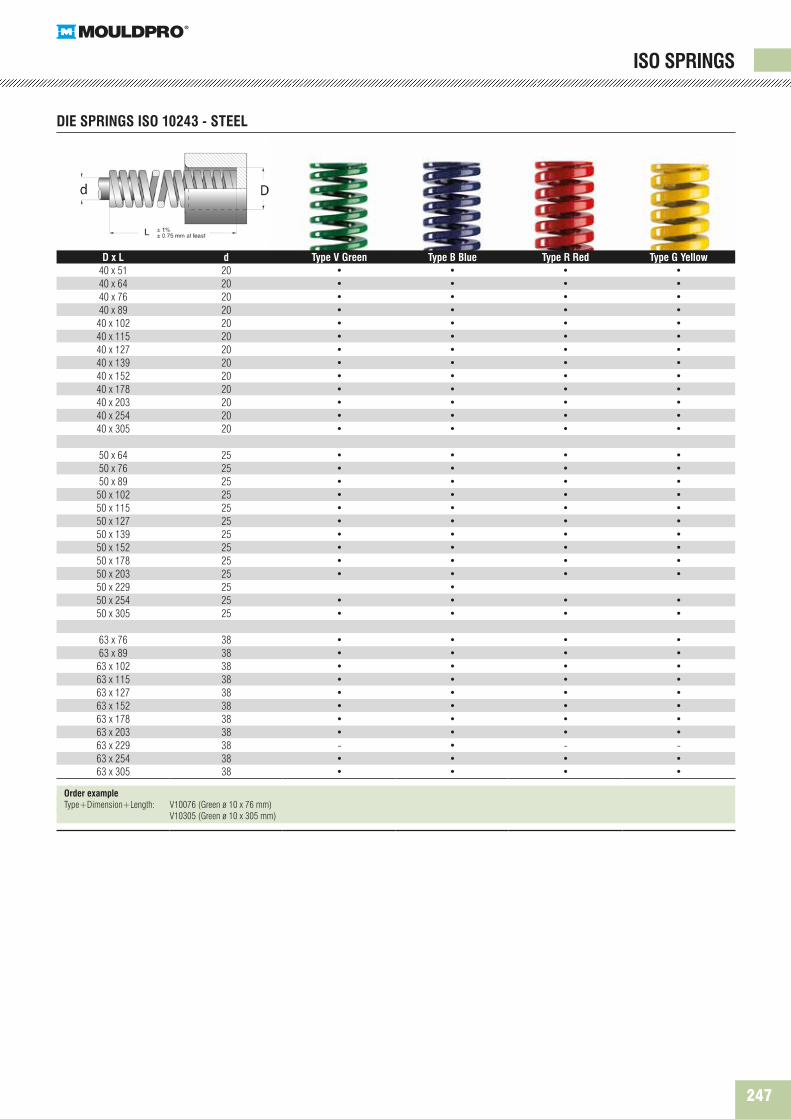
ISO SPRINGS
DIE SPRINGS ISO 10243 - STEEL
D x L d Type V Green Type B Blue Type R Red Type G Yellow25 x 25 12,5 • • • •25 x 32 12,5 • • • •25 x 38 12,5 • • • •25 x 44 12,5 • • • •25 x 51 12,5 • • • •25 x 64 12,5 • • • •25 x 76 12,5 • • • •25 x 89 12,5 • • • •25 x 102 12,5 • • • •25 x 115 12,5 • • • •25 x 127 12,5 • • • •25 x 139 12,5 • • • •25 x 152 12,5 • • • •25 x 178 12,5 • • • •25 x 203 12,5 • • • •25 x 305 12,5 • • • •
32 x 38 16 • • • •32 x 44 16 • • • •32 x 51 16 • • • •32 x 64 16 • • • •32 x 76 16 • • • •32 x 89 16 • • • •32 x 102 16 • • • •32 x 115 16 • • • •32 x 127 16 • • • •32 x 139 16 • • • •32 x 152 16 • • • •32 x 178 16 • • • •32 x 203 16 • • • •32 x 254 16 • • • •32 x 305 16 • • • •
Order exampleType+Dimension+Length: V10076 (Green ø 10 x 76 mm) V10305 (Green ø 10 x 305 mm)
247
ISO SPRINGS
DIE SPRINGS ISO 10243 - STEEL
D x L d Type V Green Type B Blue Type R Red Type G Yellow40 x 51 20 • • • •40 x 64 20 • • • •40 x 76 20 • • • •40 x 89 20 • • • •40 x 102 20 • • • •40 x 115 20 • • • •40 x 127 20 • • • •40 x 139 20 • • • •40 x 152 20 • • • •40 x 178 20 • • • •40 x 203 20 • • • •40 x 254 20 • • • •40 x 305 20 • • • •
50 x 64 25 • • • •50 x 76 25 • • • •50 x 89 25 • • • •50 x 102 25 • • • •50 x 115 25 • • • •50 x 127 25 • • • •50 x 139 25 • • • •50 x 152 25 • • • •50 x 178 25 • • • •50 x 203 25 • • • •50 x 229 25 •50 x 254 25 • • • •50 x 305 25 • • • •
63 x 76 38 • • • •63 x 89 38 • • • •63 x 102 38 • • • •63 x 115 38 • • • •63 x 127 38 • • • •63 x 152 38 • • • •63 x 178 38 • • • •63 x 203 38 • • • •63 x 229 38 - • - -63 x 254 38 • • • •63 x 305 38 • • • •
Order exampleType+Dimension+Length: V10076 (Green ø 10 x 76 mm) V10305 (Green ø 10 x 305 mm)

248 Moulding Supplies Edition 10 // www.mouldpro.com
Part No. # Digit Colour Temp. range CC200 7 Black 120˚C
Description Mouldpro Cycle Counter positively monitors mould activity, validates process monitoring data, and assists mould maintenance procedures.•Maximumoperatingtemperatureis120˚C• Counter: Non-resettable mechanical, 7-digit• Glass-filled Nylon housing• Reliable and tested quality• Specified worldwide by leading OEM’s• Supplied with serial Number• Socket head cap screws are included
MOULD CYCLE COUNTER
MOULD CYCLE COUNTER
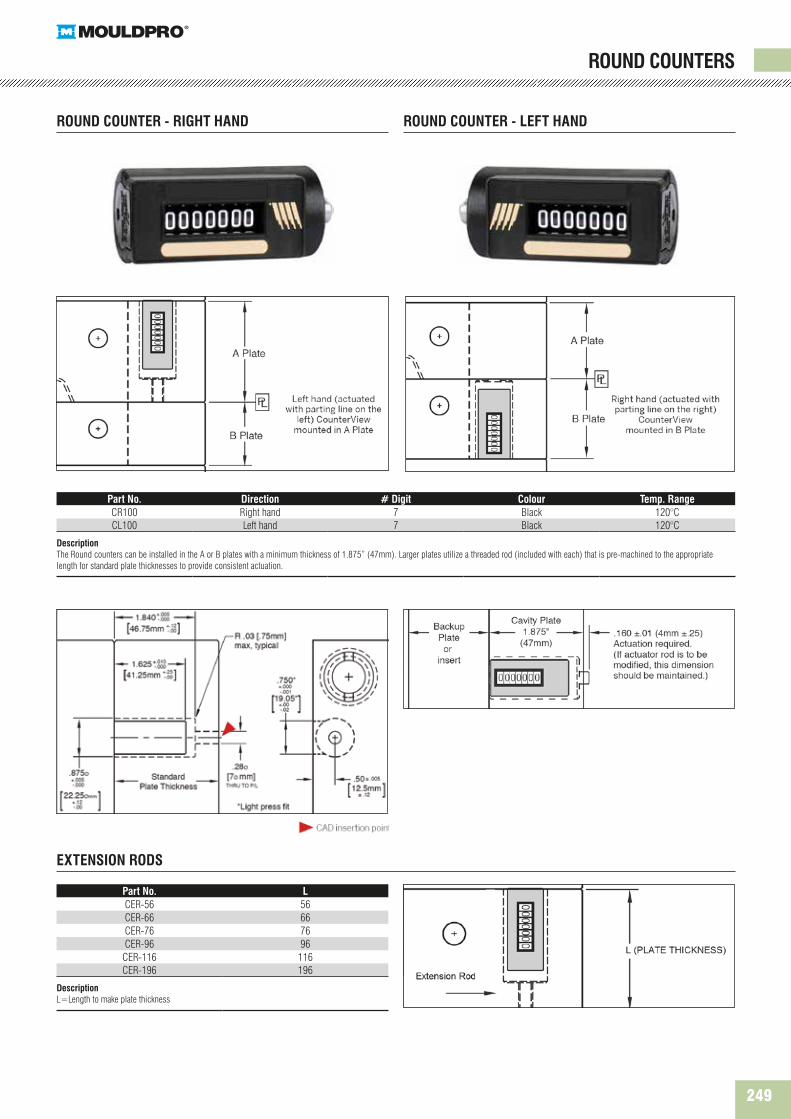
249
Part No. Direction # Digit Colour Temp. RangeCR100 Right hand 7 Black 120°CCL100 Left hand 7 Black 120°C
Description The Round counters can be installed in the A or B plates with a minimum thickness of 1.875” (47mm). Larger plates utilize a threaded rod (included with each) that is pre-machined to the appropriate length for standard plate thicknesses to provide consistent actuation.
Part No. LCER-56 56CER-66 66CER-76 76CER-96 96CER-116 116CER-196 196
Description L=Length to make plate thickness
ROUND COUNTER - RIGHT HAND
EXTENSION RODS
ROUND COUNTER - LEFT HAND
ROUND COUNTERS