
11_Acoustics DBD_Baseline.pdf
36
GE PROPRIETARY INFORMATION Acoustics Page 11.1 GE Design Basis Document Vol I [Baseline] (09 Sept 2009) 11. Acoustics Volume I Page 11.1 General ........................................................................................................................................................................ 11.2 11.2 Noise Regulations and Noise Criteria............................................................................................................. 11.4 11.3 Overview of the Noise Evaluation Process .................................................................................................. 11.7 11.4 Clarification of Guarantee Requirements..................................................................................................... 11.9 11.5 Equipment Noise Data ....................................................................................................................................... 11.12 11.6 Noise Modeling ...................................................................................................................................................... 11.13 11.7 Acoustic Mitigation Design .............................................................................................................................. 11.16 11.8 Special Design Issues ......................................................................................................................................... 11.18 11.9 Equipment Specifications ................................................................................................................................. 11.20 11.10 Compliance Testing............................................................................................................................................. 11.24 11.11 Noise Mitigation Design Practices ................................................................................................................ 11.26 11.12 Reference Materials ............................................................................................................................................ 11.32 11.13 Review Documentation Deliverables .......................................................................................................... 11.32 11.14 Appendix (Acoustical Design Process Charts) ......................................................................................... 11.33 Figure 1. Noise Evaluation Process for an Overall Power Generating Facility ......................................... 11.33 Figure 2. Noise Evaluation Process for Individual GE Scope of Supply Equipment ............................... 11.34 11.15 Revision Table ........................................................................................................................................................ 11.35 11.16 Reference List ........................................................................................................................................................ 11.35
description
af
Transcript of 11_Acoustics DBD_Baseline.pdf

GE PROPRIETARY INFORMATION Acoustics Page 11.1
GE Design Basis Document Vol I [Baseline] (09 Sept 2009)
11. Acoustics
Volume I Page 11.1 General ........................................................................................................................................................................ 11.2
11.2 Noise Regulations and Noise Criteria............................................................................................................. 11.4
11.3 Overview of the Noise Evaluation Process .................................................................................................. 11.7
11.4 Clarification of Guarantee Requirements..................................................................................................... 11.9
11.5 Equipment Noise Data....................................................................................................................................... 11.12
11.6 Noise Modeling...................................................................................................................................................... 11.13
11.7 Acoustic Mitigation Design .............................................................................................................................. 11.16
11.8 Special Design Issues ......................................................................................................................................... 11.18
11.9 Equipment Specifications................................................................................................................................. 11.20
11.10 Compliance Testing............................................................................................................................................. 11.24
11.11 Noise Mitigation Design Practices ................................................................................................................ 11.26
11.12 Reference Materials ............................................................................................................................................ 11.32
11.13 Review Documentation Deliverables .......................................................................................................... 11.32
11.14 Appendix (Acoustical Design Process Charts) ......................................................................................... 11.33
Figure 1. Noise Evaluation Process for an Overall Power Generating Facility......................................... 11.33
Figure 2. Noise Evaluation Process for Individual GE Scope of Supply Equipment ............................... 11.34
11.15 Revision Table ........................................................................................................................................................ 11.35
11.16 Reference List ........................................................................................................................................................ 11.35

GE PROPRIETARY INFORMATION Acoustics Page 11.2
GE Design Basis Document Vol I [Baseline] (09 Sept 2009)
11.1 General This document details the design and testing practices to be used with respect to plant noise and its control. The information provided herein provides an overview of the noise evaluation process and outlines the acoustical engineering issues that need to be considered on each project.
11.1.1 Owner’s Responsibility The Owner is typically responsible for all facility permitting and must identify all the applicable noise regulations or other noise criteria that must be achieved by the project and clearly communicate these requirements to GE. A clear mutual understanding of these requirements will generally form the basis for the contractual noise guarantees. GE may support the permitting effort by providing acoustical design data and expertise.
In many areas in the United States and within other countries there are no applicable noise regulations. In these instances it is good engineering practice to establish appropriate design goals for the facility directed at making its noise emissions reasonably compatible with the local environment. However, the decision to develop these goals at all and what values to set is discretionary on the part of the Owner.
11.1.2 Design Criteria Documentation A project specific Noise Guarantee Compliance Plan shall be supplied to the GE Engineering Review Board (ERB) prior to the reviews, addressing all of the elements of this “Acoustics” DBD (Design Basis Document) Section. This plan shall describe what is being done to achieve compatibility with the requirements in this DBD. This plan shall include the following information:
• List the project contract language, both actual contract wording, and a summary of the criteria.
• Identify the parties responsible for the major aspects of the acoustic design, including at a minimum: — Overall facility guarantee — Conducting acoustic modeling and evaluation — Developing individual equipment specifications — Specific equipment acoustic designs — Developing the acoustic test procedure — Performing the acoustic compliance testing
• Model summary report that clearly summarizes the modeling procedures and results, including: — A list of all equipment included in model — Basis of equipment noise data, including source of data and validity of data — Model results — Any assumptions that influence the model results — Required equipment sound level to achieve guarantee requirements — Mitigation requirements
• Provide a table of all major noise sources and the near-field and far-field sound levels requirements

GE PROPRIETARY INFORMATION Acoustics Page 11.3
GE Design Basis Document Vol I [Baseline] (09 Sept 2009)
• Equipment specific requirements, including: — Specified equipment sound level — Guarantee level provided by vendor — Vendor mitigation design — Supporting calculations — Facility test procedure
11.1.3 Definitions of Key Terms ACC - Air-cooled condenser
A-Weighted Sound Level (dBA) – The measured sound level with a frequency weighting adjustment applied to simulate the frequency response of the human ear. The human ear responds differently throughout the audio frequency. High frequency sounds appear much loader than low frequencies of the same absolute level. A-Weighting artificially adjusts up high frequencies in the 1000 to 5000 Hz range and adjusts down low frequencies to simulate a sound’s effect on the human ear.
Decibels – Sound levels are defined in terms of decibels. A decibel is a unit of level that is ten times the logarithm of the ratio of two quantities that are proportional to power.
Equivalent Sound Level (Leq) – The average of all sound energy measured during a sampling period.
Far-field – The region more than one or two major dimensions away from a source in which sound levels from the source decay with distance in a predictable manner; that is, 6 dB for every doubling of distance.
Free Field – An acoustic field largely devoid of sound waves reflected from other objects or surfaces unrelated to the source.
HP – High pressure steam turbine.
Impulse Noise – A sound that includes sudden changes in sound level over time, such as hammering.
IP - Intermediate pressure steam turbine.
L50 – The sound level exceeded 50% of a sampling period. The L50 is the median sound level.
L90 – The sound level exceeded 90% of a sampling period. A measured L90 sound level is representative of the quietest periods during a measurement period. The L90 provides a measure of the sound energy radiated by a relatively steady noise source, such as a power generating facility, while effectively “filtering out” intermittent transient noises such as traffic passes, dog barks, etc.
Lex,d - Daily personal exposure to noise as define in European Union Directive 86/188/EEC.
LP - Low pressure steam turbine.

GE PROPRIETARY INFORMATION Acoustics Page 11.4
GE Design Basis Document Vol I [Baseline] (09 Sept 2009)
Near-field – The area within about one major dimension of a source where the sound levels produced by the source do not decay linearly with distance or in a readily predictable fashion. The extent of the near-field is dependent on the size and other physical characteristics of the noise source. More generally, the term ‘near-field’ is loosely associated with the common specification distance of 1 m (3 ft).
ppeak – Maximum un-weighted instantaneous sound pressure as define in European Union Directive 86/188/EEC.
Sound Power Level (Lw) – In basic terms, the total acoustic energy radiated from a noise source. A derived quantity that depends on the size, or radiating surface area of a source. Units: dB re 1 pW (dB with reference to 1 picoWatt).
Lw = 10 * log (W/Wref)
Where:
W = acoustic power (Watts)
Wref = reference level of 1 pW
Sound Pressure Level (Lp) – A measure of the pressure fluctuations (in a medium such as air) that are produced by a noise source and perceived by the ear as sound and measured by a sound level meter. The sound pressure will vary depending on distance from a source and environmental conditions. Units: dB re 20 μPa (dB with reference to 20 microPascals)
Lp = 10 * log (P/Pref)2
Where:
P = acoustic power (Pascals)
Pref = reference level of 20 microPascals
STG - steam turbine generator
Tonal Noise – An acoustic tone is a sound frequency spectrum with the acoustic energy focused within a narrow frequency range. As an example a tuning fork produces tonal noise emissions. Tonal noise is more distinctly audible to a listener and is thereby more likely to cause disturbance to an observer than a broad-band noise. The definition of a tone differs with the regulations. A common regulatory definition of the existence of a tone is a sound signal in which any 1/3-octave band exceeds the arithmetic average of the two adjacent 1/3-octave bands by more than 5 dB.
11.2 Noise Regulations and Noise Criteria Noise (as produced by a power generating facility) can be divided into two broad categories: near-field and far-field. Near-field criteria are established to control sound levels close to the equipment in order to limit worker noise exposure and the risk of hearing damage. Far-field criteria are intended to limit environmental noise emissions to the surrounding community and prevent or minimize disturbance.

GE PROPRIETARY INFORMATION Acoustics Page 11.5
GE Design Basis Document Vol I [Baseline] (09 Sept 2009)
A number of common regulations and guidelines, briefly summarized below, exist to control both worker exposure levels and community sound levels.
11.2.1 Near-field Regulations Near-field noise regulations are intended to protect workers from noise induced hearing loss by setting exposure limits. Exposure is a function of both the sound level and the duration of time exposed to the sound level. The time element in the workplace regulations is often overlooked and it has become common practice to specify equipment at the 8-hour exposure threshold (85 dBA for OSHA) without any real consideration of the actual time workers are likely to be exposed to noise from a particular piece of equipment. In general, much higher noise levels are permissible so long as the exposure time is limited to the appropriate value. The workplace noise regulations do not identify a specific sound level within a facility but rather specify the exposure allowed by any individual working within the facility.
11.2.1.1 Occupational Safety and Health Administration (US-OSHA) The Occupational Safety and Health Administration (OSHA) regulates workplace noise in the United States.
The basic trigger level of 85 dBA is based on an average 8-hour daily exposure. If workers are exposed to noise levels at or above this threshold the employer must install signs indicating high noise areas, provide hearing protection and initiate a long-term worker hearing monitoring and conservation program.
OSHA regulations set forth a maximum exposure level of 90 dBA over an 8-hour day. The employer is required to limit worker exposure to below 90 dBA through the use of engineering noise controls or worker hearing protection, such as earplugs or earmuffs. The employer must also satisfy the 85 dBA trigger level requirements.
11.2.1.2 European Standards
11.2.1.2.1 EU Directive 2003/10/EC
The current European Union Directive 2003/10/EC on the protection of workers from noise at work was set in force on 06-February-2003. This directive replaces European Directive 86/188/EEC.
Three thresholds are defined:
• Exposure Limit Value: Lex,d = 87 dB(A) and ppeak = 200 Pa (140 dB) • Upper Exposure Action Value: Lex,d = 85 dB(A) and ppeak = 140 Pa (137 dB) • Lower Exposure Action Value: Lex,d = 80 dB(A) and ppeak = 112 Pa (135 dB)
The exposure limit values take into account the individual hearing protector, where as the action values do not. For the evaluation of the worker’s exposure, reference is made to 1999:1990 ISO standard. The exposure limit value can never be exceeded (or only in exceptional situation).
When the lower exposure action value is exceeded, the workers shall receive adequate information and training concerning risks from noise exposure, legislation etc. Also, personal ear protectors must be made available.

GE PROPRIETARY INFORMATION Acoustics Page 11.6
GE Design Basis Document Vol I [Baseline] (09 Sept 2009)
When the upper exposure action value is exceeded, workers must wear ear protectors, the employer shall apply a program of technical and organizational measures to reduce the exposure, signs must be placed and access to the noisiest areas must be restricted. Also, workers shall be able to have their hearing checked by a doctor.
11.2.1.3 Other International Standards Numerous countries have developed specific noise control regulations. Regulations must be evaluated for each individual site.
11.2.2 Far-field (Station Boundary/Community) Noise Regulations The purpose of far-field noise regulations is to protect communities from disturbance due to excess or irritating noise. To this end, most regulations, codes or guidelines generally establish specific noise limits with more stringent levels during nighttime periods. Some regulations specify absolute limits, such as 55 dBA during the day and 45 dBA at night, and others base the allowable noise level of a new source on the pre-existing ambient by permitting a largely imperceptible increase in the total environmental sound level (an increase of about 3 to 5 dBA is usually considered acceptable). If the regulations are based on an ambient increase limit, a detailed ambient survey must be conducted to definitively quantify the pre-existing ambient conditions.
The limits may also include specific requirements related to general frequency content, tones, and impulsive noises.
The following is a brief discussion of regulations for informational purposes.
11.2.2.1 United States Regulations The regulation of noise in the United States is conducted on a state and local level. Currently there are federal guidelines on noise promulgated by various departments but no legally binding regulations.
There are 11 states with nighttime noise requirements ranging from 45 dBA to 55 dBA at residential locations. Many cities, towns, and counties also have noise ordinances, which are frequently similar to or modeled after state codes.
Sites within the United States may need to satisfy the noise regulations of several jurisdictions, or may not be covered by any noise regulations at all. Regulatory criteria must be fully researched by the Owner’s legal staff for each site.
At sites with no official regulation, criteria should be established (by the client) that ensure compatible sound levels within the local community. This is best accomplished by conducting a survey of the existing ambient levels at all potentially affected sensitive receptors and developing an allowable facility contribution at each design point that will limit any increase in the total level to 5 dBA or less relative to the L90.
11.2.2.2 International Regulations Regulations differ from country to country and must be evaluated for each individual project. The Owner for each specific job site must research the applicable requirements.

GE PROPRIETARY INFORMATION Acoustics Page 11.7
GE Design Basis Document Vol I [Baseline] (09 Sept 2009)
11.2.2.3 European Directives There are no directives at the European Union level. Each country may have its own requirements.
11.2.2.4 World Bank Criteria Any projects involving World Bank funding must satisfy the bank’s noise guidelines that essentially say a facility can produce a sound level 55 dBA during the day and 45 dBA at night at all residential land uses. There is also an exemption for environments with pre-existing noise levels in excess of 45 dBA that allows the facility contribution to match the existing level (resulting in a theoretical 3 dBA increase).
Several other international lending institutions base their noise criteria on the World Bank Criteria.
11.3 Overview of the Noise Evaluation Process The noise evaluation process can be divided into two fundamental paths depending on the extent of the GE responsibility in the design. When GE, or a consortium involving GE, are ultimately responsible for meeting the Owner’s noise requirements, a more extensive design process is required than in other cases when GE is supplying only specific equipment or components.
11.3.1 GE or GE Consortium Turnkey Design For a chart providing an overview of the acoustical design process for complete facility, refer to “Figure 1. Noise Evaluation Process for an Overall Power Generating Facility” below. This procedure encompasses a complete noise evaluation for a project in which GE or a GE consortium is responsible for the entire design.
The basic steps for an overall facility acoustic evaluation are as follows.
• Review the Owner’s acoustic requirements. Confirm that the requirements are consistent with regulatory requirements and with the general site environs. Clarify the guarantee requirements and ensure they are fully understood by all parties and consistent with the GE basis of guarantee. Include compliance measurement procedures that exactly define compliance and how it will be determined.
• Identify all noise sources. The combined noise from all sources must be considered to accurately evaluate the overall noise level of the facility. No single source can be specified without considering its interaction with all other facility sources.
• Model the baseline noise emissions of the facility assuming standard equipment. • Apply noise mitigation to sources until the far-field criteria are met. The
appropriate mitigation scheme is determined and optimized through iterative modeling.
• Develop individual equipment noise specifications from the final source power levels developed in the model.
• Review vendor proposals, acoustic designs, and supporting calculations/documentation for completeness, accuracy and reliability.
• Review the acoustical design and remodel periodically as the overall facility design becomes more detailed and more specific noise information becomes available.
GE PROPRIETARY INFORMATION Acoustics Page 11.8
GE Design Basis Document Vol I [Baseline] (09 Sept 2009)
• Conduct periodic design reviews as the project progresses to ensure that all appropriate noise abatement measures are being designed, constructed, and installed properly.
• Conduct a preliminary test of the facility’s noise emissions, per the established protocol, as soon as it becomes initially operational in order to identify any problems and maximize the time available for possible correction actions.
• Implement any necessary remediation and retest. • When the preliminary testing indicates that the facility’s emissions are satisfactory,
arrange to carry out and carry out the official test. • Obtain signatory approval of the test results from the Owner, Owner’s
representative, and Bank’s engineer as appropriate.
11.3.2 GE Turbine – Generator Equipment Only Supply The acoustic evaluation process for projects in which GE provides equipment will be somewhat different. For a chart outlining the acoustic design process for individual equipment, refer to “Figure 2. Noise Evaluation Process for Individual GE Scope of Supply Equipment” below. This procedure would be followed for projects in which GE is responsible for the noise emissions from individual pieces of equipment, but not responsible for the overall facility noise.
• Review the acoustic guarantee requirements with Engineering, Procurement, and Construction (EPC) contractor. Confirm that the requirements are consistent with the overall facility guarantees. Clarify the guarantee requirements and ensure they are fully understood by all parties and consistent with the GE basis of guarantee. Include compliance measurement procedures that exactly define compliance how it will be determined.
• Determine what improvements, if any, are required to meet the requirements by reviewing all available field measurements of similar equipment.
• Design any necessary mitigation to satisfy the particular guarantee requirements. Specify the necessary acoustic performance of any procured mitigation equipment or materials.
• Specify the acoustic performance of any GE supplied equipment. • Review outside vendor’s acoustic design including any buildings or structures
enclosing GE’s equipment. Also review supporting field data or calculations for accuracy and reliability. Request more information or testing if necessary to reasonably ensure that the installed performance will be acceptable.
• Conduct periodic design reviews as the project progresses to ensure that all appropriate noise abatement measures are being designed, constructed, and installed properly.
• Conduct a preliminary test of the equipment’s noise emissions, per the established protocol, as soon as it becomes initially operational in order to identify any problems and maximize the time available for possible correction actions.
• Implement any necessary remediation and retest. • When the preliminary testing indicates that the equipment’s emissions are
satisfactory, carry out the official test. • Obtain signatory approval of the test results from the EPC Contractor and/or
others as appropriate.

GE PROPRIETARY INFORMATION Acoustics Page 11.9
GE Design Basis Document Vol I [Baseline] (09 Sept 2009)
11.4 Clarification of Guarantee Requirements Proper noise guarantee language is essential. The contractual guarantees and compliance test requirements must be completely clear, unambiguous, and uniformly understood by all parties. Clear contract language will help avoid costly disputes with many negative implications and unintended consequences can easily arise.
The following sections discuss some of the common issues associated with developing and concluding contractual guarantees and offers recommendations on avoiding common pitfalls. The contract language must be reviewed by the appropriate acoustic engineers to ensure the following provisions are clearly addressed.
11.4.1 General In-facility (Near-field) Noise Levels A very common noise requirement worldwide is a blanket limitation of 85 dBA at any point throughout a facility.
This value is nearly universal because it is the triggering threshold level for the implementation of a hearing conservation program; however, the 8-hour exposure time aspect of this noise level is generally unknown or unrecognized. Unlike in a factory setting, there are essentially no permanent workstations immediately adjacent to noisy equipment in a typical power generating facility. Any given piece of equipment is attended to on an intermittent and unpredictable basis during normal facility operation for a variety of reasons, but virtually never for 8 hours a day, every day. Consequently, while there is nothing inherently wrong with such a noise level, it is unnecessarily burdensome within the context of a power generating facility.
Moreover, this requirement is quite difficult and expensive to achieve since nearly all facilities have numerous areas where noise levels are significantly higher than 85 dBA and it is not always possible or practical to quiet these areas.
In view of this, such a requirement should not be accepted as a contractual requirement without a clear understanding of the cost implications and other difficulties by all parties.
Facility near-field noise guarantees shall be based on standard GE Near-field Guarantee language. Any deviation from this language must be reviewed and approved by the appropriate GE acoustic engineers.
The guarantee language must clearly address each item in the following checklist.
• Identify Required Sound Level and Location - Generally 85 dBA at 1 meter from equipment and 1.5 meters (5 ft) above grade. The Owner may require lower guarantee levels. Lower levels will require significant additional mitigation and associated capital costs.
• Specify Applicability of Spatial Average - The 85 dBA guarantee is based on a spatial average around the equipment. The language must identify the equipment components included in the average. Certain Owners require compliance at every location. Compliance at each location around equipment will require significant additional mitigation and associated capital costs.

GE PROPRIETARY INFORMATION Acoustics Page 11.10
GE Design Basis Document Vol I [Baseline] (09 Sept 2009)
• Specify Equipment Operation Included in Guarantee - Guarantees typically apply only to base load steady state operation. Part load operation should be excluded from the guarantee. In general, part load guarantees will not require additional mitigation, however the potential impact of part load noise emissions must be specifically evaluated for each project. If required by the Owner, any part load guarantee should be limited to one or two part load operating conditions to accommodate performance testing.
• Exclude Special Operating Conditions - The guarantee excludes transient conditions such as startup, shutdown, load changes, and emergency operations (including emergency generators). Certain equipment, in particularly steam valves and associated piping are significantly louder during these operating conditions. The inclusion of transient conditions will require additional mitigation and associated capital costs. Guarantees must also exclude steam bypass operation (steam bypass of the steam turbine directly to the condenser). Again significant mitigation will be required to satisfy guarantees under bypass conditions.
• Exclude Special Noise Criteria - The guarantee must also exclude tonal noise guarantees, impulse guarantees, and low frequency noise guarantees. These guarantees will require additional mitigation and an associated increase in capital costs.
• Specify Fuel Firing Included in Guarantee - Guarantees generally apply for all project fuel sources. Fuel oil operation may cause slightly elevated levels over gas operation.
• List Exclusions to Guarantee - The area beneath the steam turbine and the area beneath the combustion turbine (if accessible by personnel) shall be exempt from the noise guarantees. Equipment in these areas is inherently noisy and mitigation to 85 dBA is not practical. Areas within acoustic enclosures are also exempt. Project specific exemption areas should be identified for any other high noise areas.
• Identify Test Methodology and Determination of Compliance - Noise levels will be tested in accordance with GE document GEK 110392 “Standard Noise Assessment Procedure”1. This standard is adapted from ANSI/ASME PTC-36-1985 and ISO 3746. A detailed project specific test procedure shall be prepared prior to compliance testing and submitted for Owner approval. Compliance shall be based on the arithmetic average of measurements conducted at equally spaced intervals around the equipment envelope.
• Define Equipment Envelop - The equipment envelope shall be 1 meter (3 ft) away from the outermost exterior equipment surface, including piping, conduit, framework, barriers, and personnel protection devices. Inclusion of a detailed figure depicting the equipment envelope with the contract is recommended.
• Specify Condition of Equipment at Time of Test - Equipment shall be in new and clean condition, all enclosures sealed, etc. Inspection of installation quality will be conducted during Red Flag Review process. Identified defects must be corrected prior to compliance testing.

GE PROPRIETARY INFORMATION Acoustics Page 11.11
GE Design Basis Document Vol I [Baseline] (09 Sept 2009)
• Define Applicability of Background Correction - The guarantee applies to noise radiated by the GE scope of supply equipment only. Correction for background noise shall be conducted to eliminate the influence of non-facility related noise sources. Background noise measurements and corrections are only necessary if the background noise is within 10 dBA of the operation noise. Background noise rarely influences near-field sound levels.
• Specify Free-field Test Conditions and Corrections - The influence of reverberant noise shall be estimated and corrected in accordance with ANSI/ASME PTC-36-1985 and/or ISO 3746.
• Identify Party Responsible for Compliance Test - The party responsible for testing shall be stated in the contract.
11.4.2 Far-field Guarantee Language Far-field noise criteria for power facilities are project specific and will vary greatly from on project to the next. As such, the far-field guarantee language and criteria will differ greatly from project to project to correspond with the specific acoustic requirements. Project guarantee language must be developed or reviewed and approved by the GE acoustic engineers.
The guarantee language must clearly address each item in the following list:
• Define Required Sound Level and Location - The guarantees must designate specific sound levels at specific compliance locations. A map depicting the exact compliance locations is required. The compliance locations are dependent on the facility guarantee requirements. Compliance locations may include specific points along the property boundary or specific receptor locations, such as nearest residences. Stating the facility must not exceed XX dBA at the boundary is not sufficient, sound levels will vary greatly along a single property boundary. If the compliance point is a residence, the contract must state exact residential locations. The phrase “at nearest residence” is not specific, new residences could be constructed between contract signing and project commissioning.
• Specify Applicability of Spatial Average or Specify Sound Level at Specific Location - Far-field guarantees should be based on specific levels at specific points, not spatial averages. Spatial averages are only appropriate at sites in which regulations establish an average property boundary guarantee. If a spatial average is required, the specific compliance measurement points must be clearly identified. A location map is recommended.
• Specify Equipment Operation Included in Guarantee - Guarantees typically apply to base load steady state operation only. The Owner may require alternate load conditions. In general, part load guarantees will not require additional mitigation; however, the potential impact of part load noise emissions must be specifically evaluated for each project. The guarantee should be limited to one or two part load operating conditions to accommodate performance testing.
• Exclude Special Operating Conditions - The guarantee excludes transient conditions such as startup, shutdown, load changes, and emergency operations (including emergency generators). The inclusion of transient conditions will require additional mitigation and associated capital costs. Guarantees must also exclude steam bypass operation (steam bypass of the steam turbine directly to the condenser). Again significant mitigation will be required to satisfy guarantees under bypass conditions.

GE PROPRIETARY INFORMATION Acoustics Page 11.12
GE Design Basis Document Vol I [Baseline] (09 Sept 2009)
• Exclude Special Noise Criteria - The guarantee must exclude tonal noise guarantees, impulse guarantees and low frequency noise guarantees. These guarantees will require additional mitigation and an associated increase in capital costs.
• Specify Fuel Firing Included in Guarantee - Guarantees typically apply for all project fuel sources. The facility sound levels can vary with fuel due to fuel handling equipment and different combustion characteristics.
• List Exclusions to Guarantee - Emergency steam vents and emergency equipment, such as diesel generators and firewater pumps are excluded from the far-field noise guarantee.
• Identify Test Methodology and Determination of Compliance - Noise levels will be tested in accordance with GE document GEK 110392 “Standard Noise Assessment Procedure”1. The far-field test methodology is generally based on ANSI B133.8 and ISO 6190 with the exceptions of the designation of measurement locations. Measurement locations shall be at the designated compliance locations. A detailed project specific test procedure shall be prepared prior to compliance testing and submitted for Owner approval. Compliance shall be based on the measured sound level at each location, after correction for background noise and other test condition influences.
• Specify Condition of Equipment at Time of Test - Equipment shall be in new and clean condition, all acoustic mitigation equipment shall be installed and all enclosures shall be sealed with all access panels closed. Inspection of installation quality will be conducted during Red Flag Review process. Identified defects must be corrected prior to compliance testing.
• Define Applicability of Background Correction - The measured sound level shall be corrected for background noise influences. Background noise measurements and corrections are only necessary if the background noise is within 10 dBA of the operation noise.
• Specify Free-field Conditions and Corrections - The measurement positions shall be chosen to avoid large reflective surfaces. If reflections are unavoidable the effect shall be corrected in accordance with ANSI B133.8.
• Identify Party Responsible for Compliance Testing - The party responsible for testing shall be stated in the contract. The party responsible for the overall facility noise guarantee is typically responsible to conduct the noise testing.
11.5 Equipment Noise Data Equipment noise emissions shall be based on verifiable source data. Required data shall include the source sound power level, or sound pressure level at a specific far-field location, and the source near-field sound pressure level at 1 meter (3 ft) from the equipment. The data shall include overall A-weighted sound level and the sound level in each of the 9 standard octave bands ranging from 31.5 Hz to 8,000 Hz. In low frequency applications, the 8 and 16 Hz octave band sound levels should be included.
GE PROPRIETARY INFORMATION Acoustics Page 11.13
GE Design Basis Document Vol I [Baseline] (09 Sept 2009)
The following sources of noise data are generally used for noise modeling, calculations, and development of guarantees. The sources are listed in order of accuracy and reliability.
1. Direct Measurement of Identical Equipment - Ideally, noise data will be based on the direct measurement of identical equipment. Ideally, the data is obtained under acoustic laboratory conditions. As it is not practical to measure most power industry equipment under laboratory conditions, field measurement data is commonly used. All field measurements shall be conducted in accordance with applicable measurement standards such as ASME/ANSI PTC-36 or ISO 3740.
2. Direct Measurement of Similar Equipment - Noise emissions from new equipment installations for which there are no identical equipment available in the field can be estimated from data of similar equipment models. The measurements should be conducted in accordance with the procedures identified in Item 1 above. The acoustic emissions shall be corrected for any applicable scale factors such as power output, radiating surface area, etc.
3. Vendor Data - Equipment vendors shall provide noise emission data for equipment. The source of the vendor data shall be included with the noise data and the validity of the data must be verified. Vendors shall provide the following specific data for their scope of supply equipment. This data shall be incorporated into the facility acoustic model. — Guaranteed A-weighted sound power level or sound pressure level at a specific
far-field location, and the guaranteed near-field A-weighted sound pressure level at 1 meter (3 ft) from the equipment.
— Expected overall A-weighted and octave band sound power level, or sound pressure level at a specific far-field location, and the expected maximum near-field A-weighted and octave band sound pressure level at 1 meter (3 ft) from the equipment.
— Documentation and calculations that document the basis of the equipment guaranteed and expected noise emissions.
4. Estimate from Published Empirical Data - Noise emission for equipment can be estimated from published empirical data. Empirical or published data is acceptable for acoustic estimates, but is not generally of sufficient accuracy for definitive acoustic guarantees.
11.6 Noise Modeling The noise that is generated both within the facility close to the equipment (near-field) and at more distant points of concern, such as the site property line or nearest sensitive receptors (far-field) must be evaluated. Computer modeling and calculation techniques are used to simulate the noise radiated by the facility. The results of the computer modeling are used to establish the facility acoustic guarantee levels and as a tool to design the facility acoustic mitigation requirements. Accurate and meaningful modeling results are essential to develop a cost effective mitigation design. The following section outlines the procedures followed to accurately simulate the facility noise emissions.
GE PROPRIETARY INFORMATION Acoustics Page 11.14
GE Design Basis Document Vol I [Baseline] (09 Sept 2009)
11.6.1 Near-field Noise At the present time the expected near-field sound pressure levels at planned facilities are best determined from direct field measurements of similar or identical facilities already in operation. An analytical modeling approach towards evaluating near-field noise may become practical in the future when an exhaustive and sufficiently detailed library of component sound power levels has been established.
The near-field sound levels must be evaluated based on measurements conducted of similar equipment. The equipment near-field emissions shall be reviewed to identify locations in which equipment proximity and building reverberant effects shall cause exceedance of the criteria. Equipment in any potential exceedance areas shall be specified and/or mitigation shall be applied to equipment to ensure compliance with the facility near-field criteria.
11.6.2 Far-field Noise Analysis by Modeling
11.6.2.1 Noise Sources In order to develop an appropriate design that will satisfy the far-field project requirements, all the significant sources of noise in the facility must be identified, quantified, and incorporated into an analytical model. In addition to the obvious primary equipment mainly supplied by GE (combustion turbines, generators, steam turbine, etc.), there are many other sources by vendors, subcontractors or consortium partners that must also be fully accounted for, since it is the total noise level from all sources at the point of interest that is important. The omission of secondary or even minor noise sources can result in an under-prediction at the criterion point, or points, and lead to costly field retrofits.
The noise sources making up a typical combined cycle plant are fairly numerous. Some of the more significant sources that need to be considered in an overall, steady state facility model include the following:
• Combustion turbine Inlet face • Combustion turbine generator casing • Combustion turbine load compartment • Combustion turbine inlet plenum • Combustion turbine enclosure • Combustion turbine enclosure ventilation fans • Frame and bearing blower • Exhaust diffuser duct • HRSG casing walls • HRSG steam lines and valve bodies • HRSG deaerator vent • HRSG blowdown tank and vent • HRSG stack exit • Piperack steam lines • Boiler feed pumps • Transformers
GE PROPRIETARY INFORMATION Acoustics Page 11.15
GE Design Basis Document Vol I [Baseline] (09 Sept 2009)
• Cooling tower fans, motors and gearboxes • Cooling tower air inlets • Cooling tower splash • Circulating water pumps • Air cooled condenser fans, motors, and gearboxes • Turbine building wall transmission and radiation • Turbine building ventilation openings • Turbine building ventilation fans • Turbine building acoustical weak points, such as doors and removable panels • Induced draft fan building ventilation • Induced draft fan compartment ventilation • Combustion turbine package ventilation system exhausts and fans (indoor plant
configurations)
This list does not cover all possible sources and does not consider an entire second tier of additional, potentially very powerful noise sources associated with plant transients such as normal startups, shutdowns, and emergency trips.
11.6.2.2 Facility Noise Modeling The process of facility modeling and design is a matter of accurately accounting for each source in terms of its sound power level, projecting the noise of each source to a relevant design point, and summing up all the sources to determine the total facility sound pressure level. If the noise emissions are found to exceed criteria level, the model is used to identify the sources and source combinations that require mitigation to bring the total down to the required level.
11.6.2.3 Modeling Software The key element is to have reliable and accurate input sound power levels in octave bands, to ensure a meaningful output. All modeling shall be based on documented equipment noise data as available. Any assumed or estimated equipment noise data shall be clearly noted as a part of the acoustic modeling documentation.
The projection to the far-field, either expressed as specific noise levels at discrete design points or as a sound contour plot, must be conducted using commercially available software programs, such as SoundPLAN (Braunstein & Berndt GmbH), Cadna/A (DataKustik GmbH) or that all follow internationally recognized standards, most commonly ISO 9613-2 “Acoustics – Attenuation of Sound During Propagation Outdoors”.
These models calculate the noise propagation from each source to each receiver, considering source sound level, directivity, orientation of equipment, blocking by interceding buildings or terrain, distance, atmospheric effects, ground absorption, vegetative absorption and orientation of equipment. The models repeat these calculations for each source/receiver combination, in each octave band. On a typical facility design it is common to have over 100 sources and repeat the calculations over a grid of thousands of source receptor points.

GE PROPRIETARY INFORMATION Acoustics Page 11.16
GE Design Basis Document Vol I [Baseline] (09 Sept 2009)
For simple applications, involving limited sources and specific receptor locations, these calculations can be conducted using a spreadsheet type model. All calculations and assumptions conducted using a spreadsheet model must be clearly identified within the spreadsheet model.
It is important to note that the specific program that is used is much less important than one’s skill at using it. All models should be created by or rigorously checked by experienced program users only.
11.7 Acoustic Mitigation Design
11.7.1 Modeling Normally, the best approach is to first develop a baseline model of the facility that quantifies each source at a sound power level that represents its standard emissions, that is, the normal noise that is produced by the component as it is commonly installed without any special or unusual improvements intended to specifically reduce noise.
If the projected noise level from the baseline model at each point of concern satisfies the far-field requirements then no further abatement is necessary, assuming accurate model inputs. The assumed inputs then become the design requirements or specifications for each component.
If one or more points are above the requirement, then an iterative analysis is needed to determine what combination of source noise reductions both satisfies the design with a reasonable safety margin and is realistically achievable in terms of cost, feasibility, and general practicality. Because the contribution from each source is added logarithmically at the receptor point, the most dominant sources control the total level. Consequently, the greatest impact on the total comes from attenuating the highest sources and virtually no improvement results from dramatically reducing or even eliminating low ranking, low strength sources. The analytical reductions applied to the dominant sources in the model must be consciously and realistically associated with specific physical improvements (silencers, barriers, enclosures, etc.) that can reasonably be implemented. It would be a trivial matter to make the model numbers come out to any desired total. A quality analysis keeps the noise reductions, their magnitude and where they are applied solidly grounded in reality. For more information on specific noise mitigation options, refer to the “Noise Mitigation Design Practices” Section below.
11.7.2 Design Margins Since there is always a certain degree of uncertainty inherent in every noise model, it is prudent when possible, to include an explicit safety factor into every design. A nominal margin of 3 dBA is a common and reasonable target, but the actual value will often be driven by economic concerns, that is, the cost of mitigating a facility to a full 3 dBA less than the requirement can easily be prohibitive. In many cases, it is difficult to analytically demonstrate compliance with the far-field requirement(s) even after implementing numerous noise control measures. In such cases, substantial additional mitigation and significant cost will be required to provide a design margin. A 3 dBA margin, if it can be realized in a design, will normally result in a high probability that the power generating facility will meet its guarantees. When only a margin of less than 3 dBA can be managed, the inputs and assumptions used in the model need to be carefully reviewed for accuracy, completeness and reliability so that the overall risk can be evaluated. A fall back position, generally consisting of potential retrofits that can be installed to make up any shortfall, should be established to assist in this evaluation.
GE PROPRIETARY INFORMATION Acoustics Page 11.17
GE Design Basis Document Vol I [Baseline] (09 Sept 2009)
Ultimately, a decision will need to be made based on the unique set of facts associated with the project, in order to determine what noise controls should be included as a part of the fundamental design and which can be held in reserve for possible later implementation.
11.7.3 Noise Modeling and Mitigation Report Once a satisfactory design has been developed from the model study, a report shall be prepared describing the assumptions made with regard to source inputs and what will need to be done in terms of noise mitigation to meet the project noise goals. The report should include the following items as appropriate:
• The modeling software used • What has been assumed for ground effects, topography and any intervening
structures • Has internal blockage within the facility been considered • A list of all the major sources that have been considered in the baseline model and
their overall sound power levels (dBA re 1 pW) • General basis for these source levels • How the sources were represented in the model (point, plane, height, location, etc.) • A description of the physical appearance and basic construction of any turbine
buildings, including ventilation systems • How many buildings were modeled • What facility operating conditions have been assumed (base load, startup, bypass,
etc.) • The baseline facility noise levels at all points of interest, or a clear contour plot • The facility noise levels after mitigation at the same points, or a clear contour plot • An outline of what noise abatement measures are needed to realize the mitigated
performance (for example, allowable noise levels, barrier heights and configurations, enclosure descriptions, building wall and roof transmission loss, interior absorption requirements, silencer insertion losses, etc.)
11.7.4 Power Generating Facility Design Checklist (Far-field Noise) The following checklist summarizes the primary points that need be considered when designing a new facility to meet a particular far-field noise requirement:
• Establish what noise levels need to be met • Establish where these levels need to be met • Establish when, or under what operating conditions, the levels need to be met • Review the site plan to identify any topographical features or structures that will
affect noise propagation from the power block to the criterion points • Carefully review the site plan and general arrangement drawings to identify all
potential noise sources for the relevant operating conditions • Assemble octave band sound power levels for all sources from a field
measurement database or conservatively estimate the performance based on the best available information

GE PROPRIETARY INFORMATION Acoustics Page 11.18
GE Design Basis Document Vol I [Baseline] (09 Sept 2009)
• Look for modifications that can be made to the equipment layout on the site to minimize noise at the design points for little or no cost
• Evaluate the viability of these changes with other disciplines (mechanical, civil, etc.) • Develop a baseline model of the facility reflecting any beneficial equipment
reconfigurations that might be feasible • Determine the total facility sound pressure levels at the design points for
comparison to the requirements • Identify any locations where the predicted facility level is higher than the allowable
level less a 3 dBA design margin (for example, a facility level of 42 dBA or more compared to a hypothetical 45 dBA criterion)
• Iteratively apply appropriate analytical noise reductions to the dominant noise sources in the model to reduce the total level to 3 dBA less than the requirement
• Determine what physical noise control measures and equipment specification limits are associated with the numerical reductions in the model
• Develop the design in enough detail that a reasonable cost estimate for noise abatement can be determined
• Review the design for any conflicts related to performance, safety, maintenance, appearance, etc.
• Prepare a noise modeling report summarizing the analysis and required noise controls
• If a 3 dBA margin is not practical for any reason, review the model inputs and assumptions and carry out a risk assessment
• Establish a fall back position (practical and sufficiently effective retrofit options) for designs with low margin
11.8 Special Design Issues In many instances, facilities are designed and guarantees are tendered for the noise emissions specifically produced during steady state, base load operation. However, as a matter of good engineering practice, if not contractual necessity, there are a number of other noise issues that need to be carefully addressed during the design phase of each installation. Many very significant noise sources in a typical facility are inactive during normal operation and only come into play for relatively short periods of time during facility transients (startup, shutdown, emergency trips, etc.). In addition, a number of facility noises have distinctive characteristics (tonal, impulsive, excessive low frequency content, etc.) that are common sources of community disturbance, despite the fact that the presence of these characteristics often has little or no effect on the overall A-weighted sound level at a particular far-field location.
For facilities that are located within an already noisy industrial environment, these issues are largely unimportant. But, whenever a site is within several thousand meters of potentially noise sensitive uses (residences, schools, etc.), special consideration will need to be given to mitigating these noises in order to avoid an adverse community reaction to the facility.
GE PROPRIETARY INFORMATION Acoustics Page 11.19
GE Design Basis Document Vol I [Baseline] (09 Sept 2009)
11.8.1 Operating Scenarios The following noise issues shall be considered as appropriate to the circumstances surrounding each project:
• Facility startup (especially for combined cycle) — Atmospheric steam venting — Condenser hogging equipment — Steam turbine bypass — Blowdown venting — Auxiliary boilers
• Facility shutdown • Emergency trips • Tonal noise sources
— Combustion turbine inlet — Large pump motors — Transformers
• Impulsive noise - Combustion turbine inlet filter pulse cleaning • Low frequency noise - Simple cycle exhaust stacks
11.8.2 Facility Startup/Shutdown Combined Cycle Without adequate noise mitigation, normal cold or hot starts of a combined cycle facility can easily produce far-field noise levels on the order of 10 to 20 dBA above the steady state sound level of the facility. Since virtually all of this potential additional noise is associated with the steam cycle, start up is not a noise issue at simple cycle installations.
The principal transient noise sources that require attention in a typical facility include:
• Main startup vents on top the HRSG (HP, HRH, IP, LP, etc.) • The control valve bodies, lead-in piping and lower silencer casings of these vents • Deaerator vents • Atmospheric condensate drain vent discharges • Condensate drain vent stacks (normally the common destination of multiple drain
lines) • Condenser vacuum inducing equipment atmospheric discharge – steam jet air
ejector or vacuum pump • Auxiliary boiler forced draft (FD) fan motor, casing, discharge duct • Auxiliary boiler burner or fuel supply piping • Auxiliary boiler casing wall radiation • Blowdown tank vent • Blowdown tank shell radiation • HP/IP boiler feed pump HP bypass line to LP drum (pump operating in recirc mode) • Steam turbine bypass dump to wet condenser – condenser shell radiation
GE PROPRIETARY INFORMATION Acoustics Page 11.20
GE Design Basis Document Vol I [Baseline] (09 Sept 2009)
• Steam turbine bypass dump to air cooled condenser (ACC) – main steam duct radiation
• Steam turbine bypass pressure letdown valves and downstream piping • Atmospheric vents associated with steam cooling systems for combustion turbine
blades
11.8.3 Transient and Emergency Noise Emissions Discussion of transient and emergency noise emissions will be provided later.
11.8.4 Special Noise Conditions Discussion of tonal noise, impulse noise, and low frequency noise considerations will be provided later.
11.9 Equipment Specifications An acoustic specification must be developed for each piece of equipment that has the potential to contribute to near-field and far-field facility noise emissions. The results of the acoustic modeling are used to establish the required sound level for each piece of equipment.
The specified equipment sound level must account for the combined contribution of all facility noise sources. No single piece of equipment can be specified without considering the interaction of all sources.
All equipment specifications must include a near-field sound level requirement to address in-facility noise and a far-field noise requirement to address the facility property boundary noise. The near-field and far-field noise requirements are developed independent of each other to achieve the separate near-field and far-field objectives. The two values are not interdependent.
11.9.1 Equipment Near-field Equipment Specifications Near-field specifications must be developed to support the overall facility near-field requirements. The noise from each facility source has an additive effect. Additionally, buildings and other structures will contain and reverberate sound within the facility. In order to achieve an overall plant sound level, each individual source must be specified and designed to radiate noise at a level less than the guarantee value. For example, in order for the noise level within a generation building to not exceed 85 dBA at 1 meter (3 ft), it is necessary for each noise source to radiate a level of 80 dBA or less at 1 meter (3 ft). The amount of margin is dependent on the number of sources in close proximity to each other and the reflective properties of nearby structures. The actual specification level will be determined during the near-field modeling/calculation procedure.
The near-field specification language must include the items on the following checklist:
• Identify Required Sound Level and Location - The specified near-field sound level is typically 80 dBA at 1 meter (3 ft) from the equipment envelope, 1.5 meters (5 ft) above grade [to support a typical guarantee requirement of 85 dBA at 1 meter (3 feet).] Equipment specific levels must be determined through modeling/calculation.

GE PROPRIETARY INFORMATION Acoustics Page 11.21
GE Design Basis Document Vol I [Baseline] (09 Sept 2009)
• Require the Vendor to Provide Expected and Guaranteed Sound Data - Vendor shall guarantee the scope of supply equipment will meet the specified overall A-weighted sound level. The vendor shall also provide expected sound levels overall A-weighted equipment sound levels and expected levels in each octave band.
• Require Vendor to Provide Acoustic Design Data - The specification must require the vendor to submit appropriate verification that the equipment will comply with the criteria. Suitable verification could include detailed calculation, laboratory measurement of equipment, field measurement of similar equipment, etc.
• Specify Applicability of Spatial Average - The specification must be consistent with the contract language. If Owner allows spatial average, the equipment specification shall identify spatial average. If the Owner requires a maximum sound level at each location around the equipment, the specification must specify maximum level at each location. Compliance at each location around equipment will typically require additional mitigation and increased equipment cost.
• Specify Equipment Operation included in Equipment Guarantee - Equipment specifications must correspond with contract requirements. Guarantees typically apply only to base load steady state operation. Part load operation criteria must be consistent with the overall facility guarantee requirements. In general, part load guarantees will not require additional mitigation; however, the potential impact of part load noise emissions must be specifically evaluated for each equipment package.
• Identify Special Operating Condition Requirements - The equipment specifications must be consistent with the overall facility guarantee requirements. Typically the guarantee excludes transient conditions such as startup, shutdown, load changes and emergency operations (including emergency generators). The inclusion of transient conditions will require additional mitigation and associated capital costs. Guarantees must also exclude steam bypass operation (steam bypass of the steam turbine directly to the condenser). Again significant mitigation will be required to satisfy guarantees under bypass conditions.
• Identify Applicable Special Noise Criteria - The equipment specification must be consistent with the overall facility guarantee requirements. Typically the guarantee excludes tonal noise emissions, impulse emissions and low frequency noise emissions. These guarantees will require additional mitigation and an associated increase in capital costs.
• Specify Fuel Firing - Guarantees apply for all project fuel sources. • Identify Test Methodology and Determination of Compliance - Noise levels will
be tested in general accordance with the most current version of ANSI/ASME PTC-36 (or similar standard). The vendor may recommend alternate test standards subject to GE approval. The test procedure will include provisions for background corrections and a correction to free-field conditions.
• Define Equipment Governed by Specification - The specification must specifically state all equipment included in the guarantee. Typically, the noise guarantee is applicable to the combined noise emissions from all vendor scope of supply equipment.
GE PROPRIETARY INFORMATION Acoustics Page 11.22
GE Design Basis Document Vol I [Baseline] (09 Sept 2009)
• Specify Party Responsible for Compliance Test - The specification shall state the party responsible to conduct noise testing. Typically the party responsible for overall facility guarantee shall conduct near-field testing for the overall facility. If the overall facility satisfies the near-field guarantee, then no further testing is required. If the overall facility does not pass the guarantee, then the party responsible for the overall facility test will test individual equipment to determine equipment compliance with specification equipment requirements and notify the appropriate equipment vendors of any non-compliance. The equipment vendor is responsible to perform any further diagnostic testing, install all necessary mitigation and perform testing to ultimately demonstrate compliance.
11.9.2 Far-field Equipment Specifications Far-field equipment specification language must be written to ensure the individual equipment requirements support the overall facility requirements.
Equipment noise emissions shall be specified in terms of equipment sound power level. Sound power specifications define the maximum total acoustic energy that can radiate from the equipment.
Far-field sound level is often commonly specified at 122 meters (400 ft) from large equipment. Specification of sound pressure level at 122 meters (400 ft) from the equipment is appropriate for large equipment such as combustion turbines, HRSGs, cooling towers, etc. The required equipment sound pressure level at 122 meters (400 ft) is calculated from the modeling results.
Alternately, the equipment sound contribution can be specified at the facility compliance point. For example, a specification may state the cooling tower contribution alone, exclusive of all other facility equipment, shall not exceed a specific sound pressure level at a property boundary compliance location. A scaled facility arrangement drawing should accompany the specification.
Noise specification for equipment located within building must be based on equipment sound power level. A sound pressure level at 400 ft (122 meters) from equipment is not appropriate within a building. Any equipment that penetrates the building envelope, such as combustion turbine inlets, exhaust stacks, enclosure vents, shall have a far-field specification level.
The equipment specifications must be developed and approved by the GE acoustic engineers. The specification language will vary with equipment. However, specification language shall clearly address the following:
• Identify Required Sound Level and Location - Equipment sound power level shall be specified. Alternately, the equipment far-field sound levels can be specified. Far-field sound levels are most commonly specified at 122 meter (400 ft) from the equipment. The specific compliance points are at eight locations on each axis spaced 45 degrees radially around the equipment. GE’s and/or GE’s partner’s acoustic engineer for each project shall develop the specification criteria.
• Specify Applicability of Spatial Average or Sound Level at Specific Location - Far-field guarantees should be based specific sound levels at defined compliance locations, not spatial averages.

GE PROPRIETARY INFORMATION Acoustics Page 11.23
GE Design Basis Document Vol I [Baseline] (09 Sept 2009)
• Require Vendor to Provide Guarantee and Expected Sound Data - Vendors must provide a written guarantee of their scope of equipment noise emissions. The vendors must guarantee the overall A-weighted sound level at the compliance locations. The vendor must provided expected A-weighted and octave band sound levels at the compliance locations.
• Require Vendor to Provide Supporting Design Calculations and Design Information - The vendor must also provide a clear description of noise mitigation measures, a cost breakout for noise mitigation, calculations, and any supporting documentation to demonstrate the appropriateness of the acoustic design.
• Specify Equipment Operation included in Equipment Guarantee - Equipment specifications must correspond with contract requirements. Guarantees typically apply only to base load steady state operation. Part load operation criteria must be consistent with the overall facility guarantee requirements. In general, part load guarantees will not require additional mitigation; however, the potential impact of part load noise emissions must be specifically evaluated for each equipment package.
• Identify Special Operating Condition Requirements - The equipment specifications must be consistent with the overall facility guarantee requirements. The guarantee may exclude transient conditions such as startup, shutdown, load changes, and emergency operations (including emergency generators). The inclusion of transient conditions will require additional mitigation and associated capital costs. Typically the guarantee should exclude steam bypass operation (steam bypass of the steam turbine directly to the condenser). Again significant mitigation will be required to satisfy guarantees under bypass conditions.
• Identify Applicable Special Noise Criteria- The equipment specification must be consistent with the overall facility guarantee requirements. Typically the guarantee excludes tonal noise emissions, impulse emissions and low frequency noise emissions. These guarantees will require additional mitigation and an associated increase in capital costs.
• Specify Fuel Firing Included in Guarantee - Guarantees typically apply for all project fuel sources. The facility sound levels can vary with different fuel due to fuel handling equipment and different combustion characteristics. These effects must be evaluated.
• Identify Test Methodology and Determination of Compliance - Sound power level testing shall be conducted in general accordance with ANSI S12.32 and/or ISO 9614. Far-field shall be conducted in general accordance with ANSI B133.8 and/or ISO 6190. Measurements are conducted at the specified compliance locations and corrected for background noise and environmental influences. Far-field noise testing presents a special challenge because it is not possible to directly measure the contribution from a single piece of equipment, such as the HRSG, separate from other equipment, such as the combustion turbine. Equipment specific test methodologies shall be applied as necessary to address specific noise issues as they occur.
GE PROPRIETARY INFORMATION Acoustics Page 11.24
GE Design Basis Document Vol I [Baseline] (09 Sept 2009)
• Specify Party Responsible for Compliance Testing - The specification shall state the party responsible to conduct noise testing. Typically the party responsible for overall facility guarantee shall conduct testing for the overall facility. If the overall facility satisfies the far-field guarantee, then no further testing is required. If the overall facility does not pass the guarantee, then the party responsible for the overall facility test will test individual equipment to determine equipment compliance with specification equipment requirements and notify the appropriate equipment vendors of any non-compliance. The equipment vendor is responsible to perform any necessary diagnostic testing, install appropriate retrofit mitigation and perform testing to ultimately demonstrate compliance.
11.10 Compliance Testing Testing shall be conducted in accordance with a project specific test procedure that is based on GE document GEK 110392 “Standard Noise Assessment Procedure”1. The party responsible for the facility acoustic performance testing and approved by the Owner shall develop the test procedure.
11.10.1 Near-field Testing The general near-field test procedure involves measurements at equally spaced locations along an equipment envelope. Compliance determination is based on the arithmetic average of the sound level measured at each point around the equipment envelope, after correction for background noise and environmental conditions.
The near-field test procedure is based on ANSI/ASME PTC 36 and ISO 3746.
The test procedure shall identify the test requirements in the following checklist:
• Measurement Location - The measurement locations shall be at equally spaced intervals around the equipment. A figure identifying the envelope around each major equipment package should be included in the procedure.
• Measurement Parameter - Near-field sound levels are typically measured using the Leq measurement parameter.
• Measurement Duration - Near-field measurements shall be of sufficient duration to collect a meaningful sample. For steady noise sources, a 5-second average is typically sufficient. A sufficient duration is determined when the Leq value stabilizes at a single value.
• Equipment Operation - The facility shall be operating at stable conditions at base load. Measurements shall be conducted at alternate load conditions if specified in the contract. The equipment shall be in a clean and new condition. All acoustic mitigation shall be installed and functional and all enclosure doors shall be closed.
• Instrumentation Requirements - Measurements shall be conducted using an instrument that satisfies the ANSI S1.4 and ANSI 1.11 or the IEC 60651 and IEC 60804 Type 1 requirements. The instrument shall be field calibrated immediately prior to the measurements. The instrument and field calibrator shall be laboratory calibrated within 12 months prior to the survey.

GE PROPRIETARY INFORMATION Acoustics Page 11.25
GE Design Basis Document Vol I [Baseline] (09 Sept 2009)
• Background Measurements - Background measurements shall be conducted following the identical procedures used to measure the operation sound level. If the background sound levels are more than 10 dBA less than the operation sound levels, then the influence of background noise is insignificant and background measurements are not necessary. Background noise measurements are rarely necessary for near-field compliance testing.
• Atmospheric Conditions - Winds shall be less than 3 m/s (7 mph) and there shall be no precipitation during the measurements.
• Free-field Conditions - Measurements shall be corrected for free-field conditions as necessary. Corrections shall be in accordance with ANSI PTC-36 and/or ISO 3746.
11.10.2 Far-field Testing The general far-field test procedure involves measurements at the facility far-field compliance locations, as identified in the contract documents. Compliance determination is based on the measured sound level at each compliance point, after correction for background noise and environmental conditions.
The far-field test procedure is based on ANSI B133.8 and ANSI 6190.
The test procedure shall identify the test requirements in the following checklist:
• Measurement Location - The measurement locations shall be at each identified compliance location.
• Measurement Parameter - Far-field sound levels are typically measured using the Leq measurement parameter. In situations where the background noise is highly variable, such as frequent vehicle traffic on nearby roads, the L50 value should be used.
• Measurement Duration - Near-field measurements shall be of sufficient duration to collect a meaningful sample. For steady noise sources, a 30-second average is typically sufficient. Longer measurement samples may be required if intermittent background noise influences the measurement results. Sufficient measurement duration is determined when the Leq or L50 sound level stabilizes on a single value.
• Equipment Operation - The facility shall be operating at stable conditions at base load. Measurements shall be conducted at alternate load conditions if specified in the contract. The equipment shall be in a clean and new condition. All acoustic mitigation shall be installed and functional and all enclosure doors shall be closed.
• Instrumentation Requirements - Measurements shall be conducted using an instrument that satisfies the ANSI S1.4 and ANSI 1.11 or the IEC 60651 and IEC 60804 Type 1 requirements. The instrument shall be field calibrated immediately prior to the measurements. The instrument and field calibrator shall be laboratory calibrated within 12 months prior to the survey.

GE PROPRIETARY INFORMATION Acoustics Page 11.26
GE Design Basis Document Vol I [Baseline] (09 Sept 2009)
• Background Measurements - Background measurements shall be conducted following the identical procedures used to measure the operation sound level. If the background sound levels are more than 10 dBA less than the operation sound levels, then the influence of background noise is insignificant and background measurements are not necessary. Background noise must be more than 3 dBA below the operation level. If the difference between the background and operation levels is 3 dBA or less, then measurements shall be conducted at an alternate location.
• Atmospheric Conditions - Winds shall be less than 7 mph (3 m/s) and there shall be no precipitation during the measurements.
• Free-field Conditions - Measurement locations should be chosen to avoid reflective surfaces. Acoustic effects from large reflective surfaces shall be corrected in accordance with guidelines set out in ANSI B133.8 and/or ISO 6190.
• Distance Correction - If measurements are conducted at a location other than the specified compliance location, the measured levels shall be corrected for the effect of distance in accordance with guidelines set out in ANSI B133.8 and/or ISO 6190.
11.11 Noise Mitigation Design Practices
11.11.1 General Design Practices Appropriate noise abatement for a particular source not only must result in a desired noise reduction but also must:
• Not substantially impede the operational performance the equipment • Not create a safety hazard • Allow reasonable access for maintenance work on the equipment • Be economically viable to install, operate, and maintain • Be acceptable to the facility Owner/operator
Generally, every effort should be made to adhere to facility and equipment layouts of GE standard and reference plants. Nevertheless, in some cases, where warranted, it is sometimes possible to minimize noise in critical directions with changes in equipment locations or orientation done in the early stages of a project when the site arrangement has not been finalized. For example, for a partially enclosed facility it may be possible to use the turbine building as a noise barrier to the outdoor HRSGs by reversing or rotating the orientation of the power block. Alternatively, or perhaps additionally, it might be advantageous to move part or all of the facility to another area of the property further from a noise compliance point. Buffer distance is probably the most effective cost-free noise control tool.
Noisy and difficult to attenuate equipment, such as a cooling tower, gas compressor or gas pressure regulating station, should never to located immediately adjacent to a property line unless there is no alternative or unless there is clearly no noise requirement at that boundary or anywhere beyond it.
These and other similar measures should always be evaluated for feasibility early in the project, since for almost no cost, it is sometimes possible to realize substantial savings by reducing or eliminating the amount of noise controls required throughout the facility.

GE PROPRIETARY INFORMATION Acoustics Page 11.27
GE Design Basis Document Vol I [Baseline] (09 Sept 2009)
With regard to near-field noise it is important to realize that noise from multiple sources located close to one another or within the same building or enclosure will combine to produce a higher cumulative level at any particular point. Consequently, it is not enough to specify a particular component at 85 dBA at 1 meter (3 ft) and expect to actually measure 85 dBA. If a specific level is desired at a specific location it will be necessary to account for the aggregate noise from all sources and either lower the individual specification limits or provide some other means of isolation or abatement.
11.11.2 Mitigation of Individual Components What is sensible and effective with regard to attenuating the noise from specific facility components varies with the physical nature of each piece of equipment and the noise it produces. Typical options for the more major noise sources are outlined below.
11.11.2.1 Gas (Combustion) Turbine Generator Packages Standard packages are equipped with a 2.5 meter (8 ft) long parallel baffle inlet silencer, acoustically treated turbine and load compartment enclosures. A study of further noise control measures to meet specific near-field targets while also reducing far-field noise is currently nearing completion and will address this topic in detail. However, in general, the practical options consist largely of add-on noise barriers applied at several high noise areas, such as around the load compartment and inlet plenum on the side opposite the accessory module and on either side of the exhaust diffuser duct. Additional measures include ventilation fan silencing, frame blower attenuation, lube oil line lagging and upgraded inlet silencer options. For critical low noise applications, a new, all-encompassing turbine and generator enclosure is also being developed to meet future more stringent noise regulations, to eliminate the need for large turbine buildings under certain circumstances site conditions and required far-field facility performance.
11.11.2.2 Steam Turbine Generators Near-field noise from conventional steam turbine generators is normally guaranteed and evaluated around the unit on the operating deck level. Standard installations are provided with an enclosure over the HP/IP turbine section that helps contain some noise. When the STG is contained within a large turbine building, the ventilation openings in this enclosure are not acoustically treated. When the unit is outdoors, acoustical louvers are often used.
The highest noise levels occur near the exposed sections of shaft between the HP/IP turbine enclosure and the LP turbine casing, and between the LP turbine casing and the generator. Specifically, it is the gland seal around the shaft on either side of the LP turbine where the maximum noise originates. The most effective improvement that can be made to decrease near-field noise, at least on the operating deck level, is to install acoustical enclosures over these shaft areas. A design for these enclosures already exists and they are normally installed on outdoor units primarily for weather protection, and can be installed on indoor units as a noise mitigation measure. A further reduction is possible by adding acoustical blanket-type lagging to the LP turbine casing.

GE PROPRIETARY INFORMATION Acoustics Page 11.28
GE Design Basis Document Vol I [Baseline] (09 Sept 2009)
While it is possible to substantially improve the near-field noise level around an STG on the operating deck level with the improvements mentioned above, these modifications are relatively ineffective at reducing the far-field emissions from the overall steam turbine area in a facility where the STG is not enclosed in a turbine building. This is because noise from numerous steam lines and valves on the mezzanine level below the operating deck, and noise from the condenser shell and other peripheral equipment, is significantly greater than the noise radiated from the STG itself. The causes of this noise from the lower levels of the steam turbine structure are so numerous and complex that it is impractical to attempt to mitigate them on an individual basis. The best approach at reducing far-field emissions is to either close the open sides of the structure from the operating deck down with acoustical cladding, or to erect an entire steam turbine building over the steam turbine and all of its peripheral equipment. Depending on the acoustical strength of the building walls, roof and ventilation system, silencing almost any far-field requirement can theoretically be met with a full building.
11.11.2.3 HRSGs Noise from HRSGs during normal steady state operation consists mainly of:
• Internal turbine exhaust/turbulence noise transmitted through the shell casing • Stack exit noise • Noise from external steam lines, valves and vents • Valve noise from the supplemental burner gas control skid, if present • Noise from ammonia injection or other blowers, if present • Noise from the blowdown tank shell and vent, during intermittent blows • Noise from the HP/IP feedwater pump
Mitigating most or all of these sources on an individual basis can obtain a substantial reduction in overall far-field noise.
For example, the HRSG shell plate thickness can be increased from the usual 5 mm (¼ in.) to improve transmission loss. A nominal 6 dB improvement is theoretically possible for every doubling of plate thickness. For a more substantial improvement on the order of 12 to 18 dB (when it is not practical to make the casing plate the necessary thickness) freestanding barriers some 1 to 2.5 meters (4 to 8 ft) off the casing can be used. Such barriers are common on the inlet transition duct portion of the unit where wall noise is maximum. They are essentially never used on the main body because of naturally lower noise levels and numerous obstructions and pipe penetrations.
HRSG stacks are normally one of the most dominant far-field noise sources from a facility and one of the first things to require abatement. Parallel baffle silencers in the stack one or two diameters above the transition are commonplace. They can be sized to effect nearly any necessary noise reduction. But, the amount of silencing needs to be balanced with the increased pressure drop and performance loss that comes from impeding the exhaust gas flow up the stack. The allowable emissions from a stack must always be specified as an octave band sound power level spectrum, or if the unsilenced level is known with certainty, the octave band silencer insertion loss may be used.
GE PROPRIETARY INFORMATION Acoustics Page 11.29
GE Design Basis Document Vol I [Baseline] (09 Sept 2009)
Most of the other sources around the HRSG are due to piping and valve body noise, which in general terms, can be treated with an acoustically damped lagging system and/or low noise valve trim. For non-critical sites it is usually best to use conventional valves and thermal pipe lagging, and deal with any problematic noise situations on a retrofit basis when it is theoretically possible to localize and quantify the problem. Normally only extremely demanding far-field noise requirements warrant the cost of preemptive acoustical treatment of all outside piping.
The blowdown tank is normally considered a transient noise source and often left unsilenced when the facility noise guarantee is specifically for steady state noise only. But, if there are any sensitive receptors near the facility, it is good practice to at least fit the tank vent with a silencer, if not also apply acoustical lagging to the tank shell. This is a very substantial noise source during normal facility starts and at any time high flows are let into the flash tank. Moreover, it is frequently used on a nearly continuous basis during facility commissioning and performance runs to maintain optimal water chemistry, and without any acoustical treatment adversely affects the facility noise tests, which are usually on-going at that time.
When the applicable far-field noise limits on facility noise are quite low, or the distance to a criterion point is short, it often makes more economic sense to use large HRSG noise barriers (up to the drum deck level) and stack silencers, instead of attacking every source in this area on an individual basis. Although costly in its own right, this approach eliminates the need for and cost of individual noise control for the multiple sources in this area. Perhaps more importantly, it is a much more reliable method of quieting every potential noise source. Many sources, particularly those associated with steam lines and valves, are difficult to adequately anticipate and effectively mitigate.
11.11.2.4 Cooling Towers Wet cooling towers are very significant noise sources and sometimes make it difficult or impractical to meet very demanding far-field limits. Without going to extraordinary lengths, a typical cooling tower can be reduced by approximately 9 to 12 dBA at the customary specification distance of 400 feet. Beyond that, a unique and very expensive abatement design would need to be developed to suit the specific circumstances. However, under normal conditions most cooling towers are attenuated by using upgraded, low noise fans, the blades of which are more aerodynamic than on standard fans and they are usually designed to operate at a slower speed. It is important to note that one or two additional cells are often needed to maintain the same or required thermal performance (range) when low noise fans are used.
Water splash noise can be somewhat moderated (by perhaps 3 to 4 dBA) by plastic mesh mats suspended just above the basin surface to break up and soften the impact of falling droplets. For greater reductions, a barrier wall in front of the inlets can be employed and for critical applications the inlets can be fitted with prefabricated or custom-built silencer modules.
11.11.2.5 Air-cooled Condensers (ACCs) A common alternative to wet cooling towers are air-cooled condensers that directly cool and condense the LP steam turbine exhaust by forced air convection (fans blowing air over finned tubes). ACCs have the advantage that there is no water splash noise. But, they have the disadvantage that there are two to three times the number of fans in a comparable capacity cooling tower and all the fans are elevated high off the ground, allowing their noise to propagate out with little obstruction. Fan inlet noise is the principal concern. Fan discharge noise is largely eliminated in a relative sense by a small loss through the tube bundles, and a larger noise

GE PROPRIETARY INFORMATION Acoustics Page 11.30
GE Design Basis Document Vol I [Baseline] (09 Sept 2009)
reduction due to the presence of a fairly high wind wall around the tube A-frames, that acts as a reasonably effective noise barrier.
In essentially every case the only real noise reduction option is to use low noise fans, possibly in conjunction with gearbox and motor noise abatement.
During steam turbine bypass, normally a phase of a normal facility startup, but also possible under other circumstances, the entire steam production of a single HRSG or the entire facility is injected into the main steam duct beyond the turbine exhaust. This activity results in extremely high noise levels, largely because of the pressure differential between the steam upstream of the control valve and the negative pressure inside the steam duct. The very large surface area of the main duct, typically around 6 meters (20 ft) in diameter and 30 meters (100 ft) in length, gives this noise a very high sound power level.
This is an extremely severe noise problem that requires priority attention, particularly if the contract requirements limit the noise from transient operating conditions. Even if bypass operation is expressly excluded from the noise guarantees, a serious effort should still be made as a matter of good engineering practice to limit this noise if there are any sensitive receptors anywhere near the facility. At the present time, special valves and pressure letdown systems are being developed by valve suppliers in an attempt to get at the root of this problem. But, no such systems have yet been installed or field-tested. In the meantime, the current approach is to enclose the main duct in an acoustically robust shed.
11.11.2.6 Transformers In facilities that have been heavily silenced, usually by enclosure in a large building, noise from the main step-up transformers can emerge as a significant source requiring mitigation. Of particular concern with respect to off-site disturbance is the buzz or hum that occurs at twice the line frequency. This tone due to magnetostriction, can be moderately reduced by specially designed low noise cores. But, this upgrade is generally expensive and only partially effective. In most cases, the best practical mitigation method is to use simple noise barrier walls or extended firewalls.
11.11.2.7 Turbine Buildings and Ventilation Systems If a turbine building is determined to be necessary, specifically for noise control purposes, its design will be a unique function of the site layout, the applicable far-field noise requirements and where the criterion points are relative to the building. In other words, there is no single set of generic acoustical specifications that will adequately serve every project.
In general, the allowable transmission loss (TL) of the walls, roof, ventilation openings and large doors need to be derived within the context of the overall facility design from the noise model. The design process typically consists of the following steps:
• Establish the approximate physical configuration and dimensions of the building from preliminary architectural drawings or develop a conceptual design.
• Consider how the building will be ventilated and assume an appropriate arrangement of inlet or exhaust louvers and ventilation fans, including the approximate size, number, and location.

GE PROPRIETARY INFORMATION Acoustics Page 11.31
GE Design Basis Document Vol I [Baseline] (09 Sept 2009)
• Estimate the average sound pressure level spectrum inside the building (Lpins) as a whole or the specific sound pressure level incident on interior surfaces of specific parts of the building. This is best accomplished by reviewing field measurements inside similar turbine buildings, or much less reliably, via analytical calculations starting from the sound power levels of all interior sources.
• Divide the building wall and roof surfaces into elemental planar noise sources. Any area over which the incident interior sound pressure level is more or less uniform can be considered an element. At the very least each side wall and the roof will be a separate source.
• Calculate a baseline octave band sound power level spectrum (Lw) for each element by assuming a reasonable or starting wall TL, that is, the interior Lp will be attenuated by the noise reduction (NR) of the wall panel resulting in a reduced sound pressure level just outside the surface (Lpout). To be conservative, it is usually best to consider the NR of the panel equal to the TL. The radiated sound power of the element can be estimated from the relationship:
Lw = Lpins – NR + 10 log S, dB re 1 pW
1. Where S is the surface area in square meters. 2. Calculate the effective Lw of each ventilation opening and fan in a similar
manner. 3. Add all of the calculated building element sound power levels to the overall
model. 4. Identify any unacceptably high contributions at all far-field points of interest. 5. Iterate the panel TL until a satisfactory sound power level spectrum is
developed for each element.
The final TL becomes the design target to be used in specifying the wall and roof construction and in determining how much, if any, silencing needs to be applied to the ventilation openings and fans.
From a practical perspective, it is normally the low frequency performance of the walls and roof that drives the design. Good performance in this region of the spectrum requires mass and/or a multi-layered relatively complex construction. The acoustical performance specification should require a lab or field test to predetermine the compatibility of the proposed construction, with the analytical requirements derived from the model. The complexity, and therefore the cost, of the wall and roof constructions need to be carefully balanced against the silencing applied to common flanking paths, ventilation louvers, roll-up doors, and ventilation fan openings. The finest acoustical wall assembly can be easily undermined by an untreated ventilation louver of relatively small size.
In nearly all buildings or enclosures that contain equipment subject to near-field noise limits, the interior surfaces should be made to be acoustically absorptive in order to minimize reverberation and reflection. This is usually accomplished by a lining of fiberglass covered by light gage perforated metal sheet or a thin but durable wrapping of plastic sheet.
GE PROPRIETARY INFORMATION Acoustics Page 11.32
GE Design Basis Document Vol I [Baseline] (09 Sept 2009)
11.12 Reference Materials
11.12.1 ANSI – American National Standard Institute • ANSI S1.4 • ANSI S1.11 • ANSI 12.32 • ANSI B133.8 • ANSI/ASME PTC-36
11.12.2 IEC / EN Harmonized European Standards • IEC 61672 • IEC 60804
11.12.3 ISO – International Standard Organization • ISO 3740 • ISO 6190 • ISO 9613 • ISO 9614 • ISO 10494
11.12.4 OSHA / EPA 29 CFR 1910 Occupational Health and Safety Standards
OSHA home page: www.osha.gov
11.13 Review Documentation Deliverables A list of required Review Documentation Deliverables by sequence and by discipline may be found within the Volume I “General” DBD Section2.
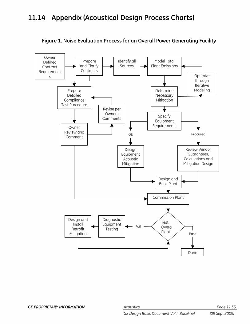
GE PROPRIETARY INFORMATION Acoustics Page 11.33
GE Design Basis Document Vol I [Baseline] (09 Sept 2009)
11.14 Appendix (Acoustical Design Process Charts)
Figure 1. Noise Evaluation Process for an Overall Power Generating Facility
Owner Defined Contract
Requirements
Prepare and Clarify Contracts
Identify all Sources
Model Total Plant Emissions
Determine Necessary Mitigation
Optimize through Iterative Modeling
Specify Equipment
Requirements
Design Equipment
Acoustic Mitigation
Design and Build Plant
Review Vendor Guarantees,
Calculations and Mitigation Design
Prepare Detailed
Compliance Test Procedure
Owner Review and Comment
Revise per Owners
Comments
Commission Plant
Test Overall Plant
Done
Diagnostic Equipment
Testing
Design and Install
Retrofit Mitigation Pass
Fail
GE Procured

GE PROPRIETARY INFORMATION Acoustics Page 11.34
GE Design Basis Document Vol I [Baseline] (09 Sept 2009)
Client Defined Specification
Requirements
Review and Clarify
Specifications
Identify Scope of
all Supplied Sources
Model /Calculate Equipment Emissions
Determine Necessary Mitigation
Optimize through Iterative
Calculation
Specify Equipment Requirements
Design Equipment
Acoustic Mitigation
Deliver Equipment
Review Vendor Guarantees, Calculations
and Mitigation Design
Commission Plant
Test Plant
(By others)
Done
Design and Install
Retrofit Mitigation
Pass
Fail
GE Components Procured Components
Diagnostic Equipment
Test
Fail
Pass
Provide Acoustic Data to Customer
Figure 2. Noise Evaluation Process for Individual GE Scope of Supply Equipment

GE PROPRIETARY INFORMATION Acoustics Page 11.35
GE Design Basis Document Vol I [Baseline] (09 Sept 2009)
11.15 Revision Table DATE AUTHOR LIST OF CHANGED SECTIONS
25 Feb 2003 C. Matis Initial Issue 14 Mar 2005 A. Dicke Updated tab and re-named to Tab 11 Acoustics-
CC/Thermal to reflect the Wind and Hydro DBD integration.
27 Jan 2009 D. Ziobroski Reformatted to new GE Corporate Format. Revised Sections 11.2.1.2.1 and 11.13.2. Deleted Section 11.12 Building Design Acoustic Requirements and added 11.13 Review Doc Deliverables.
08 Sept 2009 S. Hill Added 11.16 Reference List
GE PROPRIETARY INFORMATION Acoustics Page 11.36
GE Design Basis Document Vol I [Baseline] (09 Sept 2009)
11.16 Reference List Documents referenced within this DBD Section are noted below in the order in which they appear. These may be obtained from the PPE Project Engineer during Project Execution. (Where available, GE internal links are provided.)
1 GEK 110392 “Standard Noise Assessment Procedure” [Source file located in the GE Tech Manual Library. Click on link and enter the GEK number (no spaces) in the Search box. GEK will be shown once the GO button is selected.]
2 Volume I “General” DBD Section [Source file located in the Power Plant Systems (PPS) Reference Library]


