117758036 Pipefitter Handbook
161
Piping Joints Handbook Document No. D/UTG/054/00 03000785 (RP2066) May 2000
Transcript of 117758036 Pipefitter Handbook

7/28/2019 117758036 Pipefitter Handbook
http://slidepdf.com/reader/full/117758036-pipefitter-handbook 1/161
Piping Joints
Handbook
Document No. D/UTG/054/00
03000785 (RP2066) May 2000

7/28/2019 117758036 Pipefitter Handbook
http://slidepdf.com/reader/full/117758036-pipefitter-handbook 2/161
Acknowledgements
This Handbook was originally written and illustrated byE. Marston (BPE) on behalf of the Forties Field Group in 1991.
This version was updated in May 2000 and edited byF. Zezula (BP Amoco, UTG, Sunbury) and
C. Durden (BP Amoco, Dyce).
A “hard” pocket size version of this Handbook can beordered from XFM Reprographics, BP Amoco, Dyce Office,Tel. 01224 832547 or via En-Garde quoting Ref. RP2066.
This updated version replaces the document previouslyissued under Document No: XEG/G/94/0074.
Further information is available from:
Mechanical Consultant, UTG, Dyce;Piping & Pressure Systems Consultant, UTG, Sunbury
03000785 May 2000

7/28/2019 117758036 Pipefitter Handbook
http://slidepdf.com/reader/full/117758036-pipefitter-handbook 3/161
Piping JointsHandbook
Introduction
This booklet has been written as an introduction to and asource of general information on pipe joints.
The flanged joint appears deceptively simple but in fact thescience of flanges and joint sealing is complex and continu-ously developing. Sound joints are critical to piping integrity andplant safety.
A pipe joint thus relies on the skill and application of the fitterwho puts it together. Correct selection of materials, applicationof procedures, correct use of tools combined with the fitter’sskill are all required to ensure a joint of maximum integrity.
But mistakes have happened; choosing the wrong gaskets,using the wrong studbolts. Such mistakes cannot be ignored.
The purpose of this booklet is therefore to increase under-standing about pipe joints; from pipe specifications and how touse them, to studbolts and how to identify them. With increasedawareness and knowledge, it is expected that mistakes will beprevented.
03000785, May 2000 page 1

7/28/2019 117758036 Pipefitter Handbook
http://slidepdf.com/reader/full/117758036-pipefitter-handbook 4/161
This page left intentionally blank.
page 2 03000785, May 2000

7/28/2019 117758036 Pipefitter Handbook
http://slidepdf.com/reader/full/117758036-pipefitter-handbook 5/161
Contents Page
1. Technical Data - Company and National Standards 71.1 BP Amoco Engineering Standards 7
1.2 ANSI/API Standards 71.3 British Standards 81.4 Piping Specifications 9
2. Flanges 112.1 Flange Standards 122.2 Flange Facings 122.3 Flange Face Re-Machining 142.4 Flange Types 162.5 Flange Specification and Identification 212.6 Pipe Flanges - Do’s and Don’ts 222.7 Flange Surface Finish and Flange Distortion 23
3. Gaskets 253.1 Selection of Gasket Material 25
3.2 Fugitive Emissions 263.3 Compatibility with Fluid 273.4 Temperature 273.5 Internal Pressure 293.6 Special Considerations 293.7 RTJ (Ring Type Joint) Gaskets 323.8 Spiral Wound Gaskets 363.9 Sheet Gaskets 43
3.10 Compressed Asbestos Fibre Gasket (CAF) 463.11 Gaskets for Lined Pipework 473.12 Gaskets - Do’s and Don’ts 49
4. Compact Flanged Joints 514.1 Taper-Lok 514.2 Graylock Coupling 534.3 Other Designs 544.4 Compact Flanges Specification and Identification 55
03000785, May 2000 page 3

7/28/2019 117758036 Pipefitter Handbook
http://slidepdf.com/reader/full/117758036-pipefitter-handbook 6/161
Contents (cont’d) Page
4.5 Compact Flanges - Do’s and Don’ts 554.6 Breaking Joints 56
4.7 Making Joints 58
5. Bolting for Flanges and Covers 615.1 Bolt Material Grade 625.2 Bolt Thread 625.3 Bolt Coating/Plating 635.4 Bolt Specification and Identification 655.5 Tension Controlled Fasteners - Rotabolt 665.6 Hydraulic Bolt Tensioning 705.7 Flange and Bolt Protection 725.8 Bolting - Do’s and Don’ts 725.9 Manual Bolt Tightening 735.10 Bolt Tightening - Do’s and Don’ts 775.11 Hot Bolting 785.12 Restrictions on Hot and Odd Bolting 79
5.13 Insulation Kits for Bolts 805.14 Insulating Kit Identification and Specification 845.15 Insulating Kits - Do’s and Don’ts 84
6. Spading and Blanking of Flanges 87
7. Screwed Piping Joints 897.1 Threaded Joints 89
7.2 Sealing on a Threaded Joint 907.3 Table of Thread Jointing Compounds 927.4 Screwed Unions 947.5 Screwed Joints Specification and Identification 957.6 Screwed Joints - Do’s and Don’ts 96
8. Compression Fittings 998.1 Compression Fitting Specification and 101
Identification8.2 Compression Fittings - Do’s and Don’ts 102
page 4 03000785, May 2000

7/28/2019 117758036 Pipefitter Handbook
http://slidepdf.com/reader/full/117758036-pipefitter-handbook 7/161
Contents (cont’d) Page
9. Elastomeric O-Ring Seals 1059.1 Selection of Elastomeric O-Rings 106
9.2 Elastomeric O-Ring Failures 1079.3 Elastomeric O-Rings - Specification and 108Identification
9.4 Installation of Elastomeric O-Rings - Do’s and 109Don’ts
Appendix 1 - Miscellaneous Technical Data 1111. Bolts Material Specifications 1122. Hydraulic Bolt Tensioning 1133. Surface Finish Values for Tongue and Groove Small 113
Male/Female and Ring Joint Facings4. Chemical Resistance: Selected Elastomers and 114
Plastics
Appendix 2 - Dimensional Data 1171. ANSI B16.5 Basic Flange Dimensions 1182. ANSI B16.5 Flange Bolt Hole and Studbolt Dimensions 1263. Ring Joint Facing and RTJ Gasket Dimensions 1334. Spades for Raised Face Flanges to Suit ANSI B16.5 1405. Spades for Ring Type Joint Flanges to Suit ANSI 147
B16.56. Normal Wall Thickness for Pipe Schedule Sizes 154
7. Butt Welding Elbows and Return Bends to 156ANSI B16.9 and ANSI B16.28
8. Butt Welding Reducers, Tees, Lap Joint Stub Ends 157and Caps to ANSI B16.9
9. Welded and Seamless Pipe, BS 1600 15810. Table of Gauges 15911. Decimal Equivalents of Fractions 160
03000785, May 2000 page 5

7/28/2019 117758036 Pipefitter Handbook
http://slidepdf.com/reader/full/117758036-pipefitter-handbook 8/161
Contents Amendment Sheet
page 6 03000785, May 2000
Section Nos. ContentsDate
Amended
- Re-issue of handbook May 2000

7/28/2019 117758036 Pipefitter Handbook
http://slidepdf.com/reader/full/117758036-pipefitter-handbook 9/161
1. Technical Data - Company andNational Standards
1.1 BP Amoco Engineering StandardsThe following BP Amoco Standards are relevant to pipe flanged
joints:
RP 42-1 Piping SystemsGS 142-7 Gaskets and JointingRP 42-2 Bolting for Flanged Joints (Inch Series)GS 142-4 FlangesGS 142-5 Fittings
1.2 ANSI/API Standards
The following American Standards are used for the standardisation
of pipe joints:
ANSI BI.1 Unified Inch Screw Threads (UN and UNRThread Form)
ANSI BI.20.1 Pipe Threads, General Purpose (Inch)
ANSI B16.5 Pipe Flanges and Flanged Fittings
ANSI B16.9 Factory made Wrought Steel Butt Welding Fittings
ANSI B16.11 Forged Steel Fittings, Socket Welding andThreaded
ANSI B16.20 Ring-Joint Gaskets and Groves for Steel PipeFlanges
03000785, May 2000 page 7

7/28/2019 117758036 Pipefitter Handbook
http://slidepdf.com/reader/full/117758036-pipefitter-handbook 10/161
page 8 03000785, May 2000
ANSI B16.21 Non-Metallic Flat Gaskets for Pipe Flanges
API 601 Metallic Gaskets for RF Pipe Flanges andFlanged Connections
API 6A Specification for Wellhead and Christmas TreeEquipment
ANSI B16.47 Large Diameter Steel Flanges (NPS26 throughNPS60)
API 605 Large Diameter Carbon Steel Flanges
ANSI B16.1 Cast Iron Pipe Flanges and Flanged Fittings
1.3 British Standards
The following British Standards are also used for the standardisa-tion of pipe joints:
BS 1560 Steel Pipe Flanges and Flanged Fittings
BS 3381 Metallic Spiral Wound Gaskets for Use withFlanges to BS 1560
BS 1832 Oil Resistant Compressed Asbestos FibreJointing
BS F125 Rubber Bonded Compressed Asbestos FibreJointing
BS 3293 Carbon Steel Pipe Flanges (over 24” NB) for thePetroleum Industry
BS 3799 Steel Pipe Fittings, Screwed and Socket-Weldedfor the Petroleum Industry
BS 1580 Specification for Unified Screw Threads

7/28/2019 117758036 Pipefitter Handbook
http://slidepdf.com/reader/full/117758036-pipefitter-handbook 11/161
1.4 Piping Specifications
The Piping Specification is a document prepared during the designphase of any project. It provides the appropriate selection, specifi-
cation and material grade of pipe and piping components for a givenservice.
For all subsequent maintenance and repair on a section of pipe, thepiping specification remains as the key to correct material selection.
Before commencing any job, reference to the piping specifica-tion is essential to specify and use the correct materials. Forthe job check that you are using the latest revision of the spec-ification.
Do not rely on what was installed before must be right as thisis not always the case! If a discrepancy is found, it should bereported.
Note that a piping specification only applies to the defined plant, siteor installation. Forties, Magnus, Dimlington Terminal for exampleeach have their own piping specifications and they are NOT inter-changeable.
To use the piping specification, reference must first be made to theProcess and Instrument Diagram. Identify the section of pipe in theP&ID and a line number will be quoted, e.g:
8 -WF-1007-1A1E which is interpreted as follows:
8 - The nominal pipe size of the line.
WF - The service code. This refers to the contents of the pipe.In this instance, WF refers to Fire Water.
1007 - The pipeline number which is a unique number allocatedto a specific section or run of pipe during the designstages.
03000785, May 2000 page 9
7/28/2019 117758036 Pipefitter Handbook
http://slidepdf.com/reader/full/117758036-pipefitter-handbook 12/161
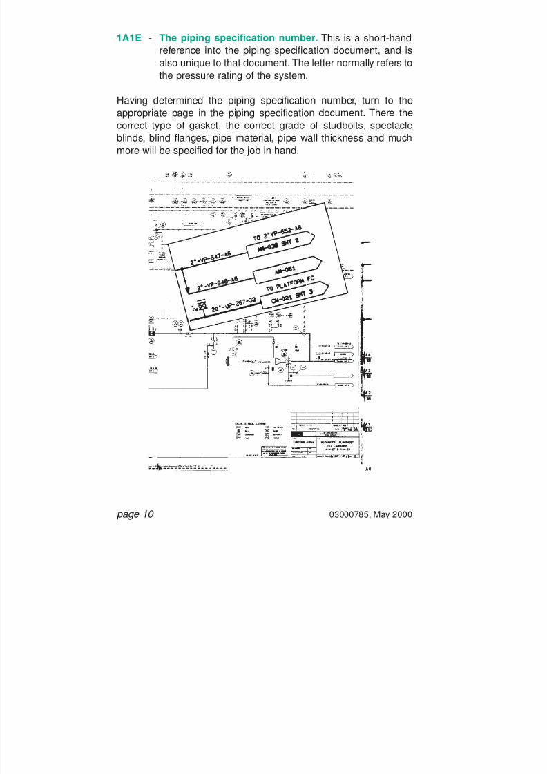
1A1E - The piping specification number. This is a short-handreference into the piping specification document, and isalso unique to that document. The letter normally refers tothe pressure rating of the system.
Having determined the piping specification number, turn to theappropriate page in the piping specification document. There thecorrect type of gasket, the correct grade of studbolts, spectacleblinds, blind flanges, pipe material, pipe wall thickness and muchmore will be specified for the job in hand.
page 10 03000785, May 2000

7/28/2019 117758036 Pipefitter Handbook
http://slidepdf.com/reader/full/117758036-pipefitter-handbook 13/161
2. Flanges
There are numerous types of flanges available. The type and mate-rial of a flange to be used is dependent on the service duty of theline. Reference to the piping specification will provide such informa-tion.
It is important to be able to accurately identify flanges as thisenables confirmation of the joint location on a P&ID, confirmationof the piping specification and thus the identification of the correctmaterials for a job.
03000785, May 2000 page 11

7/28/2019 117758036 Pipefitter Handbook
http://slidepdf.com/reader/full/117758036-pipefitter-handbook 14/161
2.1 Flange Standards
For process and utilities pipework, the two commonly used flangestandards are ANSI B16.5 (American National Standards Institute)
and BS 1560 (British Standards). A third standard, API 6A(American Petroleum Institute) specifies flanges for Wellhead andChristmas Tree Equipment.
Flanges of different standards are not normally joined. If necessaryto do so, engineering advice must first be sought to ensure the com-patibility of the mating flanges.
2.2 Flange FacingsThere are three types of flange facings commonly found on a plant.The surface finish of the facings is specified in the FlangeStandards. Note that they are refined and superseded by BPEngineering GS 142-4 - Pipe Flanges and Fittings. A section onsurface finish on the different flange facings is in this book extractedfrom GS 142-4.
page 12 03000785, May 2000
A S T M A 1
0 5 4 "
x C L A S S
1 5 0 0
W N R F

7/28/2019 117758036 Pipefitter Handbook
http://slidepdf.com/reader/full/117758036-pipefitter-handbook 15/161
a) Ring Type Joint (RTJ)
Typically found on the most severe duties, for example highpressure gas pipework. Ring type metal gaskets must be usedon this type of flange facing.
- RTJs to API 6A Type B, BS 1560 and ANSI B16.5:The seal is made by metal-to-metal contact between thegasket and the flange groove. The faces of the twoopposing flanges do not come into contact and a gap ismaintained by the presence of the gasket. Such RTJflanges will normally have raised faces but flat faces may
equally be used or specified.
- RTJs to API 6A Type BX:API 6A Type BX flanges seal by the combined effect ofgasket compression and flange face-to-face contact andwill therefore always have raised faces. The flanges alsouse special metal ring joints. A Type BX flange joint whichdoes not achieve face-to-face contact will not seal andshould not be put into service.
b) Raised Face (RF)
Sealing on a RF flange is by a flat non-metallic gasket (or a flatmetallic gasket for special applications), which fits within thebolts of the flange. The facing on a RF flange has a concentric
or phonographic groove with a controlled surface finish. If thegrooves are too deep (or a rough surface finish), then highcompression is required to flow the relatively soft gasket mate-rial into the grooves. Too shallow (exceptionally smooth surfacefinish) and again high compression is required as a leak paththen becomes more possible. It is important to always checkthe flange surface finish for imperfections which would makesealing difficult. A radial groove for example is virtually impos-sible to seal against.
03000785, May 2000 page 13
7/28/2019 117758036 Pipefitter Handbook
http://slidepdf.com/reader/full/117758036-pipefitter-handbook 16/161
Note that the surface finish on the flange facing depends onthe type of gasket being used.
Further details are given in Section 3.8 (Spiral Wound Gaskets)and 3.9 (Sheet Gaskets).
c) Flat Face (FF)
Sealing is also by compression of a flat non-metallic gasket(very rarely a flat metallic gasket), between the phono-graphic/concentric grooved surfaces of the mating FF flanges.The gasket fits over the entire face of the flange.
FF flanges are normally used on the least arduous of dutiessuch as low pressure water drains and in particular when usingcast iron, cunifer or bronze alloy, where the large gasketcontact area spreads the flange loading and reduces flangebending.
NOTE : Both ANSI B16.5 and BS 1560 specify Flat Face Flanges and Raised Face Flanges as well as RTJ Flanges. API 6A is specific to RTJ flanges only.
2.3 Flange Face Re-Machining
Flange face re-machining may be carried out in order to repair the
sealing face of a flange which has corroded, deteriorated or other-wise been damaged.
Flange face re-machining must be carried out by experienced per-sonnel using the appropriate equipment. A procedure for theprocess should be in place and must be followed.
The extent of any re-machining must be such that the flange dimen-sions still remain within the tolerance specified in the flange manu-facturing standard, ANSI B16, API 6A, BS 1560, etc. Incorrect re-
page 14 03000785, May 2000

7/28/2019 117758036 Pipefitter Handbook
http://slidepdf.com/reader/full/117758036-pipefitter-handbook 17/161
machining which reduces the flange dimensions to below theminimum specified dimensions will result in possible leakage.
03000785, May 2000 page 15
FLANGE FACERE-MACHINING

7/28/2019 117758036 Pipefitter Handbook
http://slidepdf.com/reader/full/117758036-pipefitter-handbook 18/161
2.4 Flange Types
The way in which the flange is attached to the pipe defines theflange type, as follows.
a) Weld-Neck Flange (WN)
The WN flange is butt-welded to the pipe. WN flanges are typ-ically used on arduous duties such as high pressures and/orhazardous fluids. The butt weld may be inspected by radiog-raphy or ultrasonics as well as MPI or DPI during fabrication.There is therefore a high degree of confidence in the integrityof the weld. A butt weld also has good fatigue performance andits presence does not induce high local stresses in thepipework.
b) Socket Weld Flange (SW)
Socket weld flanges are often used on high pressure, haz-ardous duties but will be limited to a nominal pipe size (NPS)of 1 1 / 2 inches.
The pipe is fillet welded to the hub of the SW flange.Radiography is not practical on the fillet weld and correct fit-upand welding is therefore crucial. The fillet weld will normally beinspected by MPI or DPI.
c) Slip-On Weld Flange (SO)
Used typically on low pressure, low hazard services such asfire water, cooling water, etc. The pipe is “double-welded” bothto the hub and the bore of the flange and again radiography isnot practical. MPI or DPI will be used to check the integrity ofthe weld.
page 16 03000785, May 2000

7/28/2019 117758036 Pipefitter Handbook
http://slidepdf.com/reader/full/117758036-pipefitter-handbook 19/161

7/28/2019 117758036 Pipefitter Handbook
http://slidepdf.com/reader/full/117758036-pipefitter-handbook 20/161
page 18 03000785, May 2000
, ,
,
,
,
,
,
,
,
,
,
,
,
,
,
,
,
,
,
,
,
,
,
,
,
,
,
,
,
,
,
,
,
,
,
,
,
,
,
,
,
,
,
,
,
,
,
,
,
,
,
,
,
,
,
,
,
,
,
,
,
,
,
,
,
,
,
,
,
,
,
,
,
,
,
,
,
,
,
,
,
,
,
,
,
,
,
,
,
,
,
,
,
,
,
,
,
,
,
,
,
,
,
,
,
,
,
,
,
,
,
,
,
,
,
,
,
,
,
,
,
,
,
,
,
,
,
,
,
,
,
,
,
,
,
,
,
,
,
,
,
,
,
,
,
,
,
,
,
,
,
,
,
,
,
,
,
,
,
,
,
,
,
,
,
,
,
,
,
,
,
,
,
,
,
,
,
,
,
,
,
,
,
,
,
,
,
,
,
,
,
,
,
,
,
,
,
,
,
,
,
,
,
,
,
,
,
,
,
,
,
,
,
,
,
,
,
,
,
,
,
,
,
,
,
,
,
,
,
,
,
,
,
,
,
,
,
,
,
,
,
,
,
,
,
,
,
,
,
,
,
,
,
,
,
,
,
,
,
,
,
,
,
,
,
,
,
,
,
,
,
,
,
,
,
,
,
,
,
,
,
,
,
,
,
,
,
,
,
,
,
,
,
,
,
,
,
,
,
,
,
,
,
,
,
,
,
,
,
,
,
,
,
,
,
,
,
,
,
,
,
,
,
,
,
,
,
,
,
,
,
,
,
,
,
,
,
,
,
,
,
,
,
,
,
,
,
,
,
,
,
,
,
,
,
,
,
,
,
,
,
,
,
,
,
,
,
,
,
,
,
,
,
,
,
,
,
,
,
,
,
,
,
,
,
,
,
,
,
,
,
,
,
,
,
,
,
,
,
,
,
,
,
,
,
,
,
,
,
,
,
,
,
,
,
,
,
,
,
,
,
,
,
,
,
,
,
,
,
,
,
,
,
,
,
,
,
,
,
,
,
,
,
,
,
,
,
,
,
,
,
,
,
,
,
,
,
,
,
,
,
,
,
,
,
,
,
,
,
,
,
,
,
,
,
,
,
,
,
,
,
,
,
,
,
,
,
,
,
,
,
,
,
,
,
,
,
,
,
,
,
,
,
,
,
,
,
,
,
,
,
,
,
,
,
,
,
,
,
,
,
,
,
,
,
,
,
,
,
,
,
,
,
,
,
,
,
,
,
,
,
,
,
,
,
,
,
,
,
,
,
,
,
,
,
,
,
,
,
,
,
,
,
,
,
,
,
,
,
,
,
,
,
,
,
,
,
,
,
,
,
,
,
,
,
,
,
,
,
,
,
,
,
,
,
,
,
,
,
,
,
,
,
,
,
,
,
,
,
,
,
,
,
,
,
,
,
,
,
,
,
,
,
,
,
,
,
,
,
,
,
,
,
,
,
,
,
,
,
,
,
,
,
,
,
,
,
,
,
,
,
,
,
,
,
,
,
,
,
,
,
,
,
,
,
,
,
,
,
,
,
,
,
,
,
,
,
,
,
,
,
,
,
,
,
,
,
,
,
,
,
,
,
,
,
,
,
,
,
,
,
,
,
,
,
,
,
,
,
,
,
,
,
,
,
,
,
,
,
,
,
,
,
,
,
,
,
,
,
,
,
,
,
,
,
,
,
,
,
,
,
,
,
,
,
,
,
,
,
,
,
,
,
,
,
,
,
,
,
,
,
,
,
,
,
,
,
,
,
,
,
,
,
,
,
,
,
,
,
,
,
,
,
,
,
,
,
,
,
,
,
,
,
,
,
,
,
,
,
,
,
,
,
,
,
,
,
,
,
,
,
,
,
,
,
,
,
,
,
,
,
,
,
,
,
,
,
,
,
,
,
,
,
,
,
,
,
,
,
,
,
,
,
,
,
,
,
,
,
,
,
,
,
,
,
,
,
,
,
,
,
,
,
,
,
,
,
,
,
,
,
,
,
,
,
,
,
,
,
,
,
,
,
,
,
,
,
,
,
,
,
,
,
,
,
,
,
,
,
,
,
,
,
,
,
,
,
,
,
,
,
,
,
,
,
,
,
,
,
,
,
,
,
,
,
,
,
,
,
,
,
,
,
,
,
,
,
,
,
,
,
,
,
,
,
,
,
,
,
,
,
,
,
,
,
,
,
,
,
,
,
,
,
,
,
,
,
,
,
,
,
,
,
,
,
,
,
,
,
,
,
,
,
,
,
,
,
,
,
,
,
,
,
,
,
,
,
,
,
,
,
,
,
,
,
,
,
,
,
,
,
,
,
,
,
,
,
,
,
,
,
,
,
,
,
,
,
,
,
,
,
,
,
,
,
,
,
,
,
,
,
,
,
,
,
,
,
,
,
,
,
,
,
,
,
,
,
,
,
,
,
,
,
,
,
,
,
,
,
,
,
,
,
,
,
,
,
,
,
,
,
,
,
,
,
,
,
,
,
,
,
,
,
,
,
,
,
,
,
,
,
,
,
,
,
,
,
,
,
,
,
,
,
,
,
,
,
,
,
,
,
,
,
,
,
,
,
,
,
,
,
,
,
,
,
,
,
,
,
,
,
,
,
,
,
,
,
,
,
,
,
,
,
,
,
,
,
,
,
,
,
,
,
,
,
,
,
,
,
,
,
,
,
,
,
,
,
,
,
,
,
,
,
,
,
,
,
,
,
,
,
,
,
,
,
,
,
,
,
,
,
,
,
,
,
,
,
,
,
,
,
,
,
,
,
,
,
,
,
,
,
,
,
,
,
,
,
,
,
,
,
,
,
,
,
,
,
,
,
,
,
,
,
,
,
,
,
,
,
,
,
,
,
,
,
,
,
,
,
,
,
,
,
,
,
,
,
,
,
,
,
,
,
,
,
,
,
,
,
,
,
,
,
,
,
,
,
,
,
,
,
,
,
,
,
,
,
,
,
,
,
,
,
,
,
,
,
,
,
,
,
,
,
,
,
,
,
,
,
,
,
,
,
,
,
,
,
,
,
,
,
,
,
,
,
,
,
,
,
,
,
,
,
,
,
,
,
,
,
,
,
,
,
,
,
,
,
,
,
,
,
,
,
,
,
,
,
,
,
,
,
,
,
,
,
,
,
,
,
,
,
,
,
,
,
,
,
,
,
,
,
,
,
,
,
,
,
,
,
,
,
,
,
,
,
,
,
,
,
,
,
,
,
,
,
,
,
,
,
,
,
,
,
,
,
,
,
,
,
,
,
,
,
,
,
,
,
,
,
,
,
,
,
,
,
,
,
,
,
,
,
,
,
,
,
,
,
,
,
,
,
,
,
,
,
,
,
,
,
,
,
,
,
,
,
,
,
,
,
,
,
,
,
,
,
,
,
,
,
,
,
,
,
,
,
,
,
,
,
,
,
,
,
,
,
,
,
,
,
,
,
,
,
,
,
,
,
,
,
,
,
,
,
,
,
,
,
,
,
,
,
,
,
,
,
,
,
,
,
, ,
,
,
,
,
,
,
,
,
,
,
,
,
,
,
,
,
,
,
,
,
,
,
,
,
,
,
,
,
,
,
,
,
,
,
,
,
,
,
,
,
,
,
,
,
,
,
,
,
,
,
,
,
,
,
,
,
,
,
,
, ,
,
,
,
,
,
,
,
,
,
,
,
,
,
,
,
,
,
,
,
,
,
,
,
,
,
,
,
,
,
,
,
,
,
,
,
,
,
,
,
,
,
,
,
,
,
,
,
,
,
,
,
,
,
,
,
,
,
, ,
,
,
,
,
,
,
,
,
,
,
,
,
,
,
,
,
,
,
,
,
,
,
,
,
,
,
,
,
,
,
,
,
,
,
,
,
,
,
,
,
,
,
,
,
,
,
,
,
,
,
,
,
,
,
,
, ,
,
,
,
,
,
,
,
,
,
,
,
,
,
,
,
,
,
,
,
,
,
,
,
,
,
,
,
,
,
,
,
,
,
,
,
,
,
,
,
,
,
,
,
,
,
,
,
,
,
,
,
,
,
, ,
,
,
,
,
,
,
,
,
,
,
,
,
,
,
,
,
,
,
,
,
,
,
,
,
,
,
,
,
,
,
,
,
,
,
,
,
,
,
,
,
,
,
,
,
,
,
,
,
,
,
,
, ,
,
,
,
,
,
,
,
,
,
,
,
,
,
,
,
,
,
,
,
,
,
,
,
,
,
,
,
,
,
,
,
,
,
,
,
,
,
,
,
,
,
,
,
,
,
,
,
,
,
, ,
,
,
,
,
,
,
,
,
,
,
,
,
,
,
,
,
,
,
,
,
,
,
,
,
,
,
,
,
,
,
,
,
,
,
,
,
,
,
,
,
,
,
,
,
,
,
,
, ,
,
,
,
,
,
,
,
,
,
,
,
,
,
,
,
,
,
,
,
,
,
,
,
,
,
,
,
,
,
,
,
,
,
,
,
,
,
,
,
,
,
,
,
,
,
, ,
,
,
,
,
,
,
,
,
,
,
,
,
,
,
,
,
,
,
,
,
,
,
,
,
,
,
,
,
,
,
,
,
,
,
,
,
,
,
,
,
,
,
,
, ,
,
,
,
,
,
,
,
,
,
,
,
,
,
,
,
,
,
,
,
,
,
,
,
,
,
,
,
,
,
,
,
,
,
,
,
,
,
,
,
,
,
, ,
,
,
,
,
,
,
,
,
,
,
,
,
,
,
,
,
,
,
,
,
,
,
,
,
,
,
,
,
,
,
,
,
,
,
,
,
,
,
,
, ,
,
,
,
,
,
,
,
,
,
,
,
,
,
,
,
,
,
,
,
,
,
,
,
,
,
,
,
,
,
,
,
,
,
,
,
,
,
, ,
,
,
,
,
,
,
,
,
,
,
,
,
,
,
,
,
,
,
,
,
,
,
,
,
,
,
,
,
,
,
,
,
,
,
,
, ,
,
,
,
,
,
,
,
,
,
,
,
,
,
,
,
,
,
,
,
,
,
,
,
,
,
,
,
,
,
,
,
,
,
, ,
,
,
,
,
,
,
,
,
,
,
,
,
,
,
,
,
,
,
,
,
,
,
,
,
,
,
,
,
,
,
,
, ,
,
,
,
,
,
,
,
,
,
,
,
,
,
,
,
,
,
,
,
,
,
,
,
,
,
,
,
,
,
, ,
,
,
,
,
,
,
,
,
,
,
,
,
,
,
,
,
,
,
,
,
,
,
,
,
,
,
,
, ,
,
,
,
,
,
,
,
,
,
,
,
,
,
,
,
,
,
,
,
,
,
,
,
,
,
, ,
,
,
,
,
,
,
,
,
,
,
,
,
,
,
,
,
,
,
,
,
,
,
,
, ,
,
,
,
,
,
,
,
,
,
,
,
,
,
,
,
,
,
,
,
,
,
, ,
,
,
,
,
,
,
,
,
,
,
,
,
,
,
,
,
,
,
,
, ,
,
,
,
,
,
,
,
,
,
,
,
,
,
,
,
,
,
, ,
,
,
,
,
,
,
,
,
,
,
,
,
,
,
,
, ,
,
,
,
,
,
,
,
,
,
,
,
,
,
, ,
,
,
,
,
,
,
,
,
,
,
,
, ,
,
,
,
,
,
,
,
,
,
, ,
,
,
,
,
,
,
,
, ,
,
,
,
,
,
, ,
,
,
,
, ,
,
, ,
,
,
,
,
,
,
,
,
,
,
,
,
,
,
,
,
,
,
,
,
,
,
,
,
,
,
,
,
,
,
,
,
,
,
,
,
,
,
,
,
,
,
,
,
,
,
,
,
,
,
,
,
,
,
,
,
,
,
,
,
,
,
,
,
,
,
,
,
,
,
,
,
,
,
,
,
,
,
,
,
,
,
,
,
,
,
,
,
,
,
,
,
,
,
,
,
,
,
,
,
,
,
,
,
,
,
,
,
,
,
,
,
,
,
,
,
,
,
,
,
,
,
,
,
,
,
,
,
,
,
,
,
,
,
,
,
,
,
,
,
,
,
,
,
,
,
,
,
,
,
,
,
,
,
,
,
,
,
,
,
,
,
,
,
,
,
,
,
,
,
,
,
,
,
,
,
,
,
,
,
,
,
,
,
,
,
,
,
,
,
,
,
,
,
,
,
,
,
,
,
,
,
,
,
,
,
,
,
,
,
,
,
,
,
,
,
,
,
,
,
,
,
,
,
,
,
,
,
,
,
,
,
,
,
,
,
,
,
,
,
,
,
,
,
,
,
,
,
,
,
,
,
,
,
,
,
,
,
,
,
,
,
,
,
,
,
,
,
,
,
,
,
,
,
,
,
,
,
,
,
,
,
,
,
,
,
,
,
,
,
,
,
,
,
,
,
,
,
,
,
,
,
,
,
,
,
,
,
,
,
,
,
,
,
,
,
,
,
,
,
,
,
,
,
,
,
,
,
,
,
,
,
,
,
,
,
,
,
,
,
,
,
,
,
,
,
,
,
,
,
,
,
,
,
,
,
,
,
,
,
,
,
,
,
,
,
,
,
,
,
,
,
,
,
,
,
,
,
,
,
,
,
,
,
,
,
,
,
,
,
,
,
,
,
,
,
,
,
,
,
,
,
,
,
,
,
,
,
,
,
,
,
,
,
,
,
,
,
,
,
,
,
,
,
,
,
,
,
,
,
,
,
,
,
,
,
,
,
,
,
,
,
,
,
,
,
,
,
,
,
,
,
,
,
,
,
,
,
,
,
,
,
,
,
,
,
,
,
,
,
,
,
,
,
,
,
,
,
,
,
,
,
,
,
,
,
,
,
,
,
,
,
,
,
,
,
,
,
,
,
,
,
,
,
,
,
,
,
,
,
,
,
,
,
,
,
,
,
,
,
,
,
,
,
,
,
,
,
,
,
,
,
,
,
,
,
,
,
,
,
,
,
,
,
,
,
,
,
,
,
,
,
,
,
,
,
,
,
,
,
,
,
,
,
,
,
,
,
,
,
,
,
,
,
,
,
,
,
,
,
,
,
,
,
,
,
,
,
,
,
,
,
,
,
,
,
,
,
,
,
,
,
,
,
,
,
,
,
,
,
,
,
,
,
,
,
,
,
,
,
,
,
,
,
,
,
,
,
,
,
,
,
,
,
,
,
,
,
,
,
,
,
,
,
,
,
,
,
,
,
,
,
,
,
,
,
,
,
,
,
,
,
,
,
,
,
,
,
,
,
,
,
,
,
,
,
,
,
,
,
,
,
,
,
,
,
,
,
,
,
,
,
,
,
,
,
,
,
,
,
,
,
,
,
,
,
,
,
,
,
,
,
,
,
,
,
,
,
,
,
,
,
,
,
,
,
,
,
,
,
,
,
,
,
,
,
,
,
,
,
,
,
,
,
,
,
,
,
,
,
,
,
,
,
,
,
,
,
,
,
,
,
,
,
,
,
,
,
,
,
,
,
,
,
,
,
,
,
,
,
,
,
,
,
,
,
,
,
,
,
,
,
,
,
,
,
,
,
,
,
,
,
,
,
,
,
,
,
,
,
,
,
,
,
,
,
,
,
,
,
,
,
,
,
,
,
,
,
,
,
,
,
,
,
,
,
,
,
,
,
,
,
,
,
,
,
,
,
,
,
,
,
,
,
,
,
,
,
,
,
,
,
,
,
,
,
,
,
,
,
,
,
,
,
,
,
,
,
,
,
,
,
,
,
,
,
,
,
,
,
,
,
,
,
,
,
,
,
,
,
,
,
,
,
,
,
,
,
,
,
,
,
,
,
,
,
,
,
,
,
,
,
,
,
,
,
,
,
,
,
,
,
,
,
,
,
,
,
,
,
,
,
,
,
,
,
,
,
,
,
,
,
,
,
,
,
,
,
,
,
,
,
,
,
,
,
,
,
,
,
,
,
,
,
,
,
,
,
,
,
,
,
,
,
,
,
,
,
,
,
,
,
,
,
,
,
,
,
,
,
,
,
,
,
,
,
,
,
,
,
,
,
,
,
,
,
,
,
,
,
,
,
,
,
,
,
,
,
,
,
,
,
,
,
,
,
,
,
,
,
,
,
,
,
,
,
,
,
,
,
,
,
,
,
,
,
,
,
,
,
,
,
,
,
,
,
,
,
,
,
,
,
,
,
,
,
,
,
,
,
,
,
,
,
,
,
,
,
,
,
,
,
,
,
,
,
,
,
,
,
,
,
,
,
,
,
,
,
,
,
,
,
,
,
,
,
,
,
,
,
,
,
,
,
,
,
,
,
,
,
,
,
,
,
,
,
,
,
,
,
,
,
,
,
,
,
,
,
,
,
,
,
,
,
,
,
,
,
,
,
,
,
,
,
,
,
,
,
,
,
,
,
,
,
,
,
,
,
,
,
,
,
,
,
,
,
,
,
,
,
,
,
,
,
,
,
,
,
,
,
,
,
,
,
,
,
,
,
,
,
,
,
,
,
,
,
,
,
,
,
,
,
,
,
,
,
,
,
,
,
,
,
,
,
,
,
,
,
,
,
,
,
,
,
,
,
,
,
,
,
,
,
,
,
,
,
,
,
,
,
,
,
,
,
,
,
,
,
,
,
,
,
,
,
,
,
,
,
,
,
,
,
,
,
,
,
,
,
,
,
,
,
,
,
,
,
,
,
,
,
,
,
,
,
,
,
,
,
,
,
,
,
,
,
,
,
,
,
,
,
,
,
,
,
,
,
,
,
,
,
,
,
,
,
,
,
,
,
,
,
,
,
,
,
,
,
,
,
,
,
,
,
,
,
,
,
,
,
,
,
,
,
,
,
,
,
,
,
,
,
,
,
,
,
,
,
,
,
,
,
,
,
,
,
,
,
,
,
,
,
,
,
,
,
,
,
,
,
,
,
,
,
,
,
,
,
,
,
,
,
,
,
,
,
,
,
,
,
,
,
,
,
,
,
,
,
,
,
,
,
,
,
,
,
,
,
,
,
,
,
,
,
,
,
,
,
,
,
,
,
,
,
,
,
,
,
,
,
,
,
,
,
,
,
,
,
,
,
,
,
,
,
,
,
,
,
,
,
,
,
,
,
,
,
,
,
,
,
,
,
,
,
,
,
,
,
,
,
,
,
,
,
,
,
,
,
,
,
,
,
,
,
,
,
,
,
,
,
,
,
,
,
,
,
,
,
,
,
,
,
,
,
,
,
,
,
,
,
,
,
,
,
,
,
,
,
,
,
,
,
,
,
,
,
,
,
,
,
,
,
,
,
,
,
,
,
,
,
,
,
,
,
,
,
,
,
,
,
,
,
,
,
,
,
,
,
,
,
,
,
,
,
,
,
,
,
,
,
,
,
,
,
,
,
,
,
,
,
,
,
,
,
,
,
,
,
,
,
,
,
,
,
,
,
,
,
,
,
,
,
,
,
,
,
,
,
,
,
,
,
,
,
,
,
,
,
,
,
,
,
,
,
,
,
,
,
,
,
,
,
,
,
,
,
,
,
,
,
,
,
,
,
,
,
,
,
,
,
,
,
,
,
,
,
,
,
,
,
,
,
,
,
,
,
,
,
,
,
,
,
,
,
,
,
,
,
,
,
,
,
,
,
,
,
,
,
,
,
,
,
,
,
,
,
,
,
,
,
,
,
,
,
,
,
,
,
,
,
,
,
,
,
,
,
,
,
,
,
,
,
,
,
,
,
,
,
,
,
,
,
,
,
,
,
,
,
,
,
,
,
,
,
,
,
,
,
,
,
,
,
,
,
,
,
,
,
,
,
,
,
,
,
,
,
,
,
,
,
,
,
,
,
,
,
,
,
,
,
,
,
,
,
,
,
,
,
,
,
,
,
,
,
,
,
,
,
,
,
,
,
,
,
,
,
,
,
,
,
,
,
,
,
,
,
,
,
,
,
,
,
,
,
,
,
,
,
,
,
,
,
,
,
,
,
,
,
,
,
,
,
,
,
,
,
,
,
,
,
,
,
,
,
,
,
,
,
,
,
,
,
,
,
,
,
,
,
,
,
,
,
,
,
,
,
,
,
,
,
,
,
,
,
,
,
,
,
,
,
,
,
,
,
,
,
,
,
,
,
,
,
,
,
,
,
,
,
,
,
,
,
,
,
,
,
,
,
,
,
,
,
,
,
,
,
,
,
,
,
,
,
,
,
,
,
,
,
,
,
,
,
,
,
,
,
,
,
,
,
,
,
,
,
,
,
,
,
,
,
,
,
,
,
,
,
,
,
,
,
,
,
,
,
,
,
,
,
,
,
,
,
,
,
,
,
,
,
,
,
,
,
,
,
,
,
,
,
,
,
,
,
,
,
,
,
,
,
,
,
,
,
,
,
,
,
,
,
,
,
,
,
,
,
,
,
,
,
,
,
,
,
,
,
,
,
,
,
,
,
,
,
,
,
,
,
,
,
,
,
,
,
,
,
,
,
,
,
,
,
,
,
,
,
,
,
,
,
,
,
,
,
,
,
,
,
,
,
,
,
,
,
,
,
,
,
,
,
,
,
,
,
,
,
,
,
,
,
,
,
,
,
,
,
,
,
,
,
,
,
,
,
,
,
,
,
,
,
,
,
,
,
,
,
,
,
,
,
,
,
,
,
,
,
,
,
,
,
,
,
,
,
,
,
,
,
,
,
,
,
,
,
,
,
,
,
,
,
,
,
,
,
,
,
,
,
,
,
,
,
,
,
,
,
,
,
,
,
,
,
,
,
,
,
,
,
,
,
,
,
,
,
,
,
,
,
,
,
,
,
,
,
,
,
,
,
,
,
,
,
,
,
,
,
,
,
,
,
,
,
,
,
,
,
,
,
,
,
,
,
,
,
,
,
,
,
,
,
,
,
,
,
,
,
,
,
,
,
,
,
,
,
,
,
,
,
,
,
,
,
,
,
,
,
,
,
,
,
,
,
,
,
,
,
,
,
,
,
,
,
,
,
,
,
,
,
,
,
,
,
,
,
,
,
,
,
,
,
,
,
,
,
,
,
,
,
,
,
,
,
,
,
,
,
,
,
,
,
,
,
,
,
,
,
,
,
,
,
,
,
,
,
,
,
,
,
,
,
,
,
,
,
,
,
,
,
,
,
,
,
,
,
,
,
,
,
,
,
,
,
,
,
,
,
,
,
,
,
,
,
,
,
,
,
,
,
,
,
,
,
,
,
,
,
,
,
,
,
,
,
,
,
,
,
,
,
,
,
,
,
,
,
,
,
,
,
,
,
,
,
,
,
,
,
,
,
,
,
,
,
,
,
,
,
,
,
,
,
,
,
,
,
,
,
,
,
,
,
,
,
,
,
,
,
,
,
,
,
,
,
,
,
,
,
,
,
,
,
,
,
,
,
,
,
,
,
,
,
,
,
,
,
,
,
,
,
,
,
,
,
,
,
,
,
,
,
,
,
,
,
,
,
,
,
,
,
,
,
,
,
,
,
,
,
,
,
Raised Face Weld Neck Flange
Ring Type Joint Flange

7/28/2019 117758036 Pipefitter Handbook
http://slidepdf.com/reader/full/117758036-pipefitter-handbook 21/161

7/28/2019 117758036 Pipefitter Handbook
http://slidepdf.com/reader/full/117758036-pipefitter-handbook 22/161
page 20 03000785, May 2000
,
,
,
,
,
,
,
,
,
,
,
,
,
,
,
,
,
,
,
,
,
,
,
,
,
,
,
,
,
,
,
,
,
,
,
,
,
,
,
,
,
,
,
,
,
,
,
,
,
,
,
,
,
,
,
,
,
,
,
,
,
,
,
,
,
,
,
,
,
,
,
,
,
,
,
,
,
,
,
,
,
,
,
,
,
,
,
,
,
,
,
,
,
,
,
,
,
,
,
,
,
,
,
,
,
,
,
,
,
,
,
,
,
,
,
,
,
,
,
,
,
,
,
,
,
,
,
,
,
,
,
,
,
,
,
,
,
,
,
,
,
,
,
,
,
,
,
,
,
,
,
,
,
,
,
,
,
,
,
,
,
,
,
,
,
,
,
,
,
,
,
,
,
,
,
,
,
,
,
,
,
,
,
,
,
,
,
,
,
,
,
,
,
,
,
,
,
,
,
,
,
,
,
,
,
,
,
,
,
,
,
,
,
,
,
,
,
,
,
,
,
,
,
,
,
,
,
,
,
,
,
,
,
,
,
,
,
,
,
,
,
,
,
,
,
,
,
,
,
,
,
,
,
,
,
,
,
,
,
,
,
,
,
,
,
,
,
,
,
,
,
,
,
,
,
,
,
,
,
,
,
,
,
,
,
,
,
,
,
,
,
,
,
,
,
,
,
,
,
,
,
,
,
,
,
,
,
,
,
,
,
,
,
,
,
,
,
,
,
,
,
,
,
,
,
,
,
,
,
,
,
,
,
,
,
,
,
,
,
,
,
,
,
,
,
,
,
,
,
,
,
,
,
,
,
,
,
,
,
,
,
,
,
,
,
,
,
,
,
,
,
,
,
,
,
,
,
,
,
,
,
,
,
,
,
,
,
,
,
,
,
,
,
,
,
,
,
,
,
,
,
,
,
,
,
,
,
,
,
,
,
,
,
,
,
,
,
,
,
,
,
,
,
,
,
,
,
,
,
,
,
,
,
,
,
,
,
,
,
,
,
,
,
,
,
,
,
, ,
,
,
,
,
,
,
,
,
,
,
,
,
,
,
,
,
,
,
,
,
,
,
,
,
,
,
,
,
,
,
,
,
,
,
,
,
,
,
,
,
,
,
,
,
,
,
,
,
,
,
,
,
,
,
,
,
,
,
,
,
,
,
,
,
,
,
,
,
,
,
,
,
,
,
,
,
,
,
,
,
,
,
,
,
,
,
,
,
,
,
,
,
,
,
,
,
,
,
,
,
,
,
,
,
,
,
,
,
,
,
,
,
,
,
,
,
,
,
,
,
,
,
,
,
,
,
,
,
,
,
,
,
,
,
,
,
,
,
,
,
,
,
,
,
,
,
,
,
,
,
,
,
,
,
,
,
,
,
,
,
,
,
,
,
,
,
,
,
,
,
,
,
,
,
,
,
,
,
,
,
,
,
,
,
,
,
,
,
,
,
,
,
,
,
,
,
,
,
,
,
,
,
,
,
,
,
,
,
,
,
,
,
,
,
,
,
,
,
,
,
,
,
,
,
,
,
,
,
,
,
,
,
,
,
,
,
,
,
,
,
,
,
,
,
,
,
,
,
,
,
,
,
,
,
,
,
,
,
,
,
,
,
,
,
,
,
,
,
,
,
,
,
,
,
,
,
,
,
,
,
,
,
,
,
,
,
,
,
,
,
,
,
,
,
,
,
,
,
,
,
,
,
,
,
,
,
,
,
,
,
,
,
,
,
,
,
,
,
,
,
,
,
,
,
,
,
,
,
,
,
,
,
,
,
,
,
,
,
,
,
,
,
,
,
,
,
,
,
,
,
,
,
,
,
,
,
,
,
,
,
,
,
,
,
,
,
,
,
,
,
,
,
,
,
,
,
,
,
,
,
,
,
,
,
,
,
,
,
,
,
,
,
,
,
,
,
,
,
,
,
,
,
,
,
,
,
,
,
,
,
,
,
,
,
,
,
,
,
,
,
,
,
,
,
,
,
,
,
,
,
,
,
,
,
,
,
,
,
,
,
,
,
,
,
,
,
,
,
,
,
,
,
,
,
,
,
,
,
,
,
,
,
,
,
,
,
,
,
,
,
,
,
,
,
,
,
,
,
,
,
,
,
,
,
,
,
,
,
,
,
,
,
,
,
,
,
,
,
,
,
,
,
,
,
,
,
,
,
,
,
,
,
,
,
,
,
,
,
,
,
,
,
,
,
,
,
,
,
,
,
,
,
,
,
,
,
,
,
,
,
,
,
,
,
,
,
,
,
,
,
,
,
,
,
,
,
,
,
,
,
,
,
,
,
,
,
,
,
,
,
,
,
,
,
,
,
,
,
,
,
,
,
,
,
,
,
,
,
,
,
,
,
,
,
,
,
,
,
,
,
,
,
,
,
,
,
,
,
,
,
,
,
,
,
,
,
,
,
,
,
,
,
,
,
,
,
,
,
,
,
,
,
,
,
,
,
,
,
,
,
,
,
,
,
,
,
,
,
,
,
,
,
,
,
,
,
,
,
,
,
,
,
,
,
,
,
,
,
,
,
,
,
,
,
,
,
,
,
,
,
,
,
,
,
,
,
,
,
,
,
,
,
,
,
,
,
,
,
,
,
,
,
,
,
,
,
,
,
,
,
,
,
,
,
,
,
,
,
,
,
,
,
,
,
,
,
,
,
,
,
,
,
,
,
,
,
,
,
,
,
,
,
,
,
,
,
,
,
,
,
,
,
,
,
,
,
,
,
,
,
,
,
,
,
,
,
,
,
,
,
,
,
,
,
,
,
,
,
,
,
,
,
,
,
,
,
,
,
,
,
,
,
,
,
,
,
,
,
,
,
,
,
,
,
,
,
,
,
,
,
,
,
,
,
,
,
,
,
,
,
,
,
,
,
,
,
,
,
,
,
,
,
,
,
,
,
,
,
,
,
,
,
,
,
,
,
,
,
,
,
,
,
,
,
,
,
,
,
,
,
,
,
,
,
,
,
,
,
,
,
,
,
,
,
,
,
,
,
,
,
,
,
,
,
,
,
,
,
,
,
,
,
,
,
,
,
,
,
,
,
,
,
,
,
,
,
,
,
,
,
,
,
,
,
,
,
,
,
,
,
,
,
,
,
,
,
,
,
,
,
,
,
,
,
,
,
,
,
,
,
,
,
,
,
,
,
,
,
,
,
,
,
,
,
,
,
,
,
,
,
,
,
,
,
,
,
,
,
,
,
,
,
,
,
,
,
,
,
,
,
,
,
,
,
,
,
,
,
,
,
,
,
,
,
,
,
,
,
,
,
,
,
,
,
,
,
,
,
,
,
,
,
,
,
,
,
,
,
,
,
,
,
,
,
,
,
,
,
,
,
,
,
,
,
,
,
,
,
,
,
,
,
,
,
,
,
,
,
,
,
,
,
,
,
,
,
,
,
,
,
,
,
,
,
,
,
,
,
,
,
,
,
,
,
,
,
,
,
,
,
,
,
,
,
,
,
,
,
,
,
,
,
,
,
,
,
,
,
,
,
,
,
,
,
,
,
,
,
,
,
,
,
,
,
,
,
,
,
,
,
,
,
,
,
,
,
,
,
,
,
,
,
,
,
,
,
,
,
,
,
,
,
,
,
,
,
,
,
,
,
,
,
,
,
,
,
,
,
,
,
,
,
,
,
,
,
,
,
,
,
,
,
,
,
,
,
,
,
,
,
,
,
,
,
,
,
,
,
,
,
,
,
,
,
,
,
,
,
,
,
,
,
,
,
,
,
,
,
,
,
,
,
,
,
,
,
,
,
,
,
,
,
,
,
,
,
,
,
,
,
,
,
,
,
,
,
,
,
,
,
,
,
,
,
,
,
,
,
, ,
,
,
,
,
,
,
,
,
,
,
,
,
,
,
,
, ,
,
,
,
,
,
,
,
,
,
,
,
,
,
,
,
,
,
, ,
,
,
,
,
,
,
,
,
,
,
,
,
,
,
,
,
,
,
,
, ,
,
,
,
,
,
,
,
,
,
,
,
,
,
,
,
,
,
,
,
,
,
, ,
,
,
,
,
,
,
,
,
,
,
,
,
,
,
,
,
,
,
,
,
,
,
,
, ,
,
,
,
,
,
,
,
,
,
,
,
,
,
,
,
,
,
,
,
,
,
,
,
,
,
, ,
,
,
,
,
,
,
,
,
,
,
,
,
,
,
,
,
,
,
,
,
,
,
,
,
,
,
,
, ,
,
,
,
,
,
,
,
,
,
,
,
,
,
,
,
,
,
,
,
,
,
,
,
,
,
,
,
,
,
, ,
,
,
,
,
,
,
,
,
,
,
,
,
,
,
,
,
,
,
,
,
,
,
,
,
,
,
,
,
,
,
,
, ,
,
,
,
,
,
,
,
,
,
,
,
,
,
,
,
,
,
,
,
,
,
,
,
,
,
,
,
,
,
,
,
,
,
, ,
,
,
,
,
,
,
,
,
,
,
,
,
,
,
,
,
,
,
,
,
,
,
,
,
,
,
,
,
,
,
,
,
,
,
,
, ,
,
,
,
,
,
,
,
,
,
,
,
,
,
,
,
,
,
,
,
,
,
,
,
,
,
,
,
,
,
,
,
,
,
,
,
,
,
, ,
,
,
,
,
,
,
,
,
,
,
,
,
,
,
,
,
,
,
,
,
,
,
,
,
,
,
,
,
,
,
,
,
,
,
,
,
,
,
,
, ,
,
,
,
,
,
,
,
,
,
,
,
,
,
,
,
,
,
,
,
,
,
,
,
,
,
,
,
,
,
,
,
,
,
,
,
,
,
,
,
,
,
, ,
,
,
,
,
,
,
,
,
,
,
,
,
,
,
,
,
,
,
,
,
,
,
,
,
,
,
,
,
,
,
,
,
,
,
,
,
,
,
,
,
,
,
,
, ,
,
,
,
,
,
,
,
,
,
,
,
,
,
,
,
,
,
,
,
,
,
,
,
,
,
,
,
,
,
,
,
,
,
,
,
,
,
,
,
,
,
,
,
,
,
, ,
,
,
,
,
,
,
,
,
,
,
,
,
,
,
,
,
,
,
,
,
,
,
,
,
,
,
,
,
,
,
,
,
,
,
,
,
,
,
,
,
,
,
,
,
,
,
,
, ,
,
,
,
,
,
,
,
,
,
,
,
,
,
,
,
,
,
,
,
,
,
,
,
,
,
,
,
,
,
,
,
,
,
,
,
,
,
,
,
,
,
,
,
,
,
,
,
,
,
, ,
,
,
,
,
,
,
,
,
,
,
,
,
,
,
,
,
,
,
,
,
,
,
,
,
,
,
,
,
,
,
,
,
,
,
,
,
,
,
,
,
,
,
,
,
,
,
,
,
,
,
,
, ,
,
,
,
,
,
,
,
,
,
,
,
,
,
,
,
,
,
,
,
,
,
,
,
,
,
,
,
,
,
,
,
,
,
,
,
,
,
,
,
,
,
,
,
,
,
,
,
,
,
,
,
, ,
,
,
,
,
,
,
,
,
,
,
,
,
,
,
,
,
,
,
,
,
,
,
,
,
,
,
,
,
,
,
,
,
,
,
,
,
,
,
,
,
,
,
,
,
,
,
,
,
,
,
,
, ,
,
,
,
,
,
,
,
,
,
,
,
,
,
,
,
,
,
,
,
,
,
,
,
,
,
,
,
,
,
,
,
,
,
,
,
,
,
,
,
,
,
,
,
,
,
,
,
,
,
,
,
, ,
,
,
,
,
,
,
,
,
,
,
,
,
,
,
,
,
,
,
,
,
,
,
,
,
,
,
,
,
,
,
,
,
,
,
,
,
,
,
,
,
,
,
,
,
,
,
,
,
,
,
,
, ,
,
,
,
,
,
,
,
,
,
,
,
,
,
,
,
,
,
,
,
,
,
,
,
,
,
,
,
,
,
,
,
,
,
,
,
,
,
,
,
,
,
,
,
,
,
,
,
,
,
,
,
, ,
,
,
,
,
,
,
,
,
,
,
,
,
,
,
,
,
,
,
,
,
,
,
,
,
,
,
,
,
,
,
,
,
,
,
,
,
,
,
,
,
,
,
,
,
,
,
,
,
,
,
,
, ,
,
,
,
,
,
,
,
,
,
,
,
,
,
,
,
,
,
,
,
,
,
,
,
,
,
,
,
,
,
,
,
,
,
,
,
,
,
,
,
,
,
,
,
,
,
,
,
,
,
,
, ,
,
,
,
,
,
,
,
,
,
,
,
,
,
,
,
,
,
,
,
,
,
,
,
,
,
,
,
,
,
,
,
,
,
,
,
,
,
,
,
,
,
,
,
,
,
,
,
,
,
,
,
,
,
,
,
,
,
,
,
,
,
,
,
,
,
,
,
,
,
,
,
,
,
,
,
,
,
,
,
,
,
,
,
,
,
,
,
,
,
,
,
,
,
,
,
,
,
,
,
,
,
,
,
,
,
,
,
,
,
,
,
,
,
,
,
,
,
,
,
,
,
,
,
,
,
,
,
,
,
,
,
,
,
,
,
,
,
,
,
,
,
,
,
,
,
,
,
,
,
,
,
,
,
,
,
,
,
,
,
,
,
,
,
,
,
,
,
,
,
,
,
,
,
,
,
,
,
,
,
,
,
,
,
,
,
,
,
,
,
,
,
,
,
,
,
,
,
,
,
,
,
,
,
,
,
,
,
,
,
,
,
,
,
,
,
,
,
,
,
,
,
,
,
,
,
,
,
,
,
,
,
,
,
,
,
,
,
,
,
,
,
,
,
,
,
,
,
,
,
,
,
,
,
,
,
,
,
,
,
,
,
,
,
,
,
,
,
,
,
,
,
,
,
,
,
,
,
,
,
,
,
,
,
,
,
,
,
,
,
,
,
,
,
,
,
,
,
,
,
,
,
,
,
,
,
,
,
,
,
,
,
,
,
,
,
,
,
,
,
,
,
,
,
,
,
,
,
,
,
,
,
,
,
,
,
,
,
,
,
,
,
,
,
,
,
,
,
,
,
,
,
,
,
,
,
,
,
,
,
,
,
,
,
,
,
,
,
,
,
,
,
,
,
,
,
,
,
,
,
,
,
,
,
,
,
,
,
,
,
,
,
,
,
,
,
,
,
,
,
,
,
,
,
,
,
,
,
,
,
,
,
,
,
,
,
,
,
,
,
,
,
,
,
,
,
,
,
,
,
,
,
,
,
,
,
,
,
,
,
,
,
,
,
,
,
,
,
,
,
,
,
,
,
,
,
,
,
,
,
,
,
,
,
,
,
,
,
,
,
,
,
,
,
,
,
,
,
,
,
,
,
,
,
,
,
,
,
,
,
,
,
,
,
,
,
,
,
,
,
,
,
,
,
,
,
,
,
,
,
,
,
,
,
,
,
,
,
,
,
,
,
,
,
,
,
,
,
,
,
,
,
,
,
,
,
,
,
,
,
,
,
,
,
,
,
,
,
,
,
,
,
,
,
,
,
,
,
,
,
,
,
,
,
,
,
,
,
,
,
,
,
,
,
,
,
,
,
,
,
,
,
,
,
,
,
,
,
,
,
,
,
,
,
,
,
,
,
,
,
,
,
,
,
,
,
,
,
,
,
,
,
,
,
,
,
,
,
,
,
,
,
,
,
,
,
,
,
,
,
,
,
,
,
,
,
,
,
,
,
,
,
,
,
,
,
,
,
,
,
,
,
,
,
,
,
,
,
,
,
,
,
,
,
,
,
,
,
,
,
,
,
,
,
,
,
,
,
,
,
,
,
,
,
,
,
,
,
,
,
,
,
,
,
,
,
,
,
,
,
,
,
,
,
,
,
,
,
,
,
,
,
,
,
,
,
,
,
,
,
,
,,
,
,
,
,
,
,
,
,
,
,
,,
,
,
,
,
,
,
,
,
,
,
,
,
,,
,
,
,
,
,
,
,
,
,
,
,
,
,
,
,,
,
,
,
,
,
,
,
,
,
,
,
,
,
,
,
,
,,
,
,
,
,
,
,
,
,
,
,
,
,
,
,
,
,
,
,
,,
,
,
,
,
,
,
,
,
,
,
,
,
,
,
,
,
,
,
,
,
,,
,
,
,
,
,
,
,
,
,
,
,
,
,
,
,
,
,
,
,
,
,,
,
,
,
,
,
,
,
,
,
,
,
,
,
,
,
,
,
,
,
,
,,
,
,
,
,
,
,
,
,
,
,
,
,
,
,
,
,
,
,
,
,
,
,
,
,
,
,
,
,
,
,
,
,
,
,
,
,
,
,
,
,
,
,
,
,
,
,
,
,
,
,
,
,
,
,
,
,
,
,
,
,
,
,
,
,
,
,
,
,
,
,
,
,
,
,
,
,
,
,
,
,
,
,
,
,
,
,
,
,
,
,
,
,
,
,
,
,
,
,
,
,
,
,
,
,
,
,
,
,
,
,
,
,
,
,
,
,
,
,
,
,
,
,
,
,
,
,
,
,
,
,
,
,
,
,
,
,
,
,
,
,
,
,
,
,
,
,
,
,
,
,
,
,
,
,
,
,
,
,
,
,
,
,
,
,
,
,
,
,
,
,
,
,
,
,
,
,
,
,
,
,
,
,
,
,
,
,
,
,
,
,
,
,
,
,
,
,
,
,
,
,
,
,
,
,
,
,
,
,
,
,
,
,
,
,
,
,
,
,
,
,
,
,
,
,
,
,
,
,
,
,
,
,
,
,
,
,
,
,
,
,
,
,
,
,
,
,
,
,
,
,
,
,
,
,
,
,
,
,
,
,
,
,
,
,
,
,
,
,
,
,
,
,
,
,
,
,
,
,
,
,
,
,
,
,
,
,
,
,
,
,
,
,
,
,
,
,
,
,
,
,
,
,
,
,
,
,
,
,
,
,
,
,
,
,
,
,
,
,
,
,
,
,
,
,
,
,
,
,
,
,
,
,
,
,
,
,
,
,
,
,
,
,
,
,
,
,
,
,
,
,
,
,
,
,
,
,
,
,
,
,
,
,
,
,
,
,
,
,
,,
,
,
,
,
,
,
,
,
,
,
,
,
,
,
,
,
,
,
,
,
,,
,
,
,
,
,
,
,
,
,
,
,
,
,
,
,
,
,
,
,
,
,,
,
,
,
,
,
,
,
,
,
,
,
,
,
,
,
,
,
,
,
,,
,
,
,
,
,
,
,
,
,
,
,
,
,
,
,
,
,
,
,,
,
,
,
,
,
,
,
,
,
,
,
,
,
,
,
,
,,
,
,
,
,
,
,
,
,
,
,
,
,
,
,
,,
,
,
,
,
,
,
,
,
,
,
,
,
,,
,
,
,
,
,
,
,
,
,
,
,,
,
,
,
,
,
,
,
,
,,
,
,
,
,
,
,
,
,
,
,
,
,
,
,
,
,
,
,
,
,
,
,
,
,
,
,
,
,
,
,
,
,
,
,
,
,
,
,
,
,
,
,
,
,
,
,
,
,
,
,
,
,
,
,
,
,
,
,
,
,
,
,
,
,
,
,
,
,
,
,
,
,
,
,
,
,
,
,
,
,
,
,
,
,
,
,
,
,
,
,
,
,
,
,
,
,
,
,
,
,
,
,
,
,
,
,
,
,
,
,
,
,
,
,
,
,
,
,
,
,
,
,
,
,
,
,
,
,
,
,
,
,
,
,
,
,
,
,
,
,
,
,
,
,
,
,
,
,
,
,
,
,
,
,
,
,
,
,
,
,
,
,
,
,
,
,
,
,
,
,
,
,
,
,
,
,
,
,
,
,
,
,
,
,
,
,
,
,
,
,
,
,
,
,
,
,
,
,
,
,
,
,
,
,
,
,
,
,
,
,
,
,
,
,
,
,
,
,
,
,
,
,
,
,
,
,
,
,
,
,
,
,
,
,
,
,
,
,
,
,
,
,
,
,
,
,
,
,
,
,
,
,
,
,
,
,
,
,
,
,
,
,
,
,
,
,
,
,
,
,
,
,
,
,
,
,
,
,
,
,
,
,
,
,
,
,
,
,
,
,
,
,
,
,
,
,
,
,
,
,
,
,
,
,
,
,
,
,
,
,
,
,
,
,
,
,
,
,
,
,
,
,
,
,
,
,
,
,
,
,
,
,
,
,
,
,
,
,
,
,
,
,
,
,
,
,
,
,
,
,
,
,
,
,
,
,
,
,
,
,
,
,
,
,
,
,
,
,
,
,
,
,
,
,
,
,
,
,
,
,
,
,
,
,
,
,
,
,
,
,
,
,
,
,
,
,
,
,
,
,
,
,
,
,
,
,
,
,
,
,
,
,
,
,
,
,
,
,
,
,
,
,
,
,
,
,
,
,
,
,
,
,
,
,
,
,
,
,
,
,
,
,
,
,
,
,
,
,
,
,
,
,
,
,
,
,
,
,
,
,
,
,
,
,
,
,
,
,
,
,
,
,
,
,
,
,
,
,
,
,
,
,
,
,
,
Swivel Ring Flange
Composite Lap Joint Flange

7/28/2019 117758036 Pipefitter Handbook
http://slidepdf.com/reader/full/117758036-pipefitter-handbook 23/161
2.5 Flange Specification and Identification
2.5.1 Specification
A flange is specified by the following information:
a) Type and Facing: i.e. whether the flange is for example “WeldNeck, RTJ” or “Socket Weld, RF”.
b) Nominal Pipe Size: required for all flanges, usually in inches.
c) Flange Pressure Class: required for all flanges, e.g. Class150, 300, 900, 1500, 2500 etc.
d) Standard: i.e. ANSI B16.5, BS 1560, API 6A, API 605 or ASMEB16.47.
e) Material: a material specification must be stated and will be asquoted in the piping specification.
f) Pipe Schedule: only for Weld Neck, Socket Weld, CompositeLap Joint and Swivel Ring flanges where the flange bore mustmatch that of the pipe, e.g. Schedule 10, 30, 40, ,80, 120, 160,etc.
2.5.2 Identification
Normally, the flange specification will be hard stamped on theflange. In the case of existing plant, the information may not belegible and it is then necessary to identify the flange by visualobservation and physical measurement.
a) Visual Observation: required to identify the type of flange andtype of gasket used.
b) Physical Measurement: required to identify the nominal boreand the class of the flange. Check the number of studbolts,
03000785, May 2000 page 21

7/28/2019 117758036 Pipefitter Handbook
http://slidepdf.com/reader/full/117758036-pipefitter-handbook 24/161
studbolt diameter, studbolt Pitch Circle Diameter (PCD) andthe flange thickness. Compare these figures with standardflange data as found.
2.6 Pipe Flanges - Do s and Don ts
Do s
a) Always visually inspect the surface finish of the flange for inju-rious defects. It should be clean, degreased and free of any
defects, nicks or burrs. The permissible imperfections in flangesurface finish specified in ASME B16.5, Table 3 are not allowedfor critical applications. Raised Face and Flat Face flangesshould also be checked for flatness with a straight edge.
b) All rust and burrs must be removed, small scratches should beremoved by polishing, other defects may mean componentreplacement.
c) Check the phonographic or concentric groove on the face ofRaised Face and Flat Face flanges. Any radial defects forexample will be virtually impossible to seal against.
d) RTJ grooves must be kept scrupulously clean, corrosion freeand undamaged.
Don ts
a) When cleaning a flange face, never use a tool which maydamage the surface finish. A soft wire brush is recommended.
b) Do not use unnecessary force, say by tirforing or pulling, tobring flanges which are clearly misaligned together. This mayoverstress adjacent pipework and will make sealing of the
page 22 03000785, May 2000

7/28/2019 117758036 Pipefitter Handbook
http://slidepdf.com/reader/full/117758036-pipefitter-handbook 25/161
flanged joint difficult and unreliable. Instead, report the situ-ation.
c) Do not mate flanges manufactured to different standardsunless specified in an approved design.
2.7 Flange Surface Finish and FlangeDistortion
To create a seal, gasket has to fill up the voids in the flange surfacepresent because of surface finish and any flange rotation (or rela-tive distortion) between the two surfaces.
The flange surface will thus give a broad indication of which gasketmaterials are likely to be suitable. Finishes of standard raised faceflanges usually fall within the range 3.2 to 12.5 mm, but this may beexpressed in micro inch or roughness number.
a) Sheet Jointing
The recommended surface finish for the compressed fibre jointing (above a thickness of 1 mm) is 3.2 mm to 12.5 mm Ra(125 m in 500 min. CLA). These values are also used for graphitelaminate (above a thickness of 0.8mm).
For tongue and groove flange facings or for very thin gaskets(0.4mm or below), a surface finish of 1.6 mm to 6.3 mm Ra (63to 200 in. CLA) is possible.
03000785, May 2000 page 23
Surface Finish
Roughness Number (BS 308)
Micro metre mm
Micro inch
12.5
500
N10
6.3
250
N9
3.2
125
N8
1.6
63
N7

7/28/2019 117758036 Pipefitter Handbook
http://slidepdf.com/reader/full/117758036-pipefitter-handbook 26/161
Surface finishes below 1.6 mm are not recommended due totheir negative effect on creep resistance of the gasket.
b) Spiral Wound Gasketing
This type of gasket requires a range of surface finishesdependent upon the application:
- General - 3.2 mm to 5.1 mm Ra (125 min. to 200 min. CLA)- Critical - 3.2 mm Ra (125 min. CLA).- Vacuum applications - 2.0 mm Ra (80 min. CLA)
c) Solid Flat Metal
A surface finish in the order of 1.6 mm Ra is acceptable but formore critical conditions, a finish no more coarse than 0.8 mmRa is preferred. Again for optimum performance, the smootherthe flange surface finish, the better the performance.
d) Metallic Ring Joint Gaskets
The angled surfaces (typically 23°) of both grooves and octag-onal gaskets and the contact faces of oval gaskets should havea surface finish no rougher than 1.6 mm Ra.
e) Machining of Flange Faces
Under no circumstances should flange seating surfaces bemachined in a manner that tool marks extend radially acrossthe seating surface. Such tool marks are practically impos-sible to seal regardless of the type of gasket being used.
page 24 03000785, May 2000

7/28/2019 117758036 Pipefitter Handbook
http://slidepdf.com/reader/full/117758036-pipefitter-handbook 27/161
3. Gaskets
3.1 Selection of Gasket Material
Assuming the mating flanges are in existence, the selection of thecorrect gasket material involves a logical series of considerationsand these are considered in turn.
03000785, May 2000 page 25
DO NOT CUT ORDEFORM A GASKETTO FIT A FLANGE.

7/28/2019 117758036 Pipefitter Handbook
http://slidepdf.com/reader/full/117758036-pipefitter-handbook 28/161
3.2 Fugitive Emissions
Heightened awareness with regard to Health and the Environmentis leading to new and more stringent standard procedures and leg-
islation. The goal is to reduce emissions to target levels currentlybased on the best available technology. These targets will inevitablybecome tighter in the future. Large companies have been aware ofthe issues for a number of years and will have a major part to playin the future standards and legislation. As early as 1994, FugitiveEmissions had a major impact on meeting the challenge set bymajor petrochemicals companies. Some companies set their ownhigh standards ahead of incumbent legislation.
Fugitive Emission Sources (Fluid Sealing Association)
PVRC (Pressure Vessel Research Committee)
page 26 03000785, May 2000
0
10
20
30
40
50
60
70
80
Valves Relief
Valves
Pumps Pipe
Flanges
Compressor Other
TightnessClassification
Mass Leak Rate per mmfor Gasket DiameterClassification
Economy
StandardTight
0.2 mg/sec.mm
0.002 mg/sec.mm0.00002 mg/sec.mm
T2
T2T3
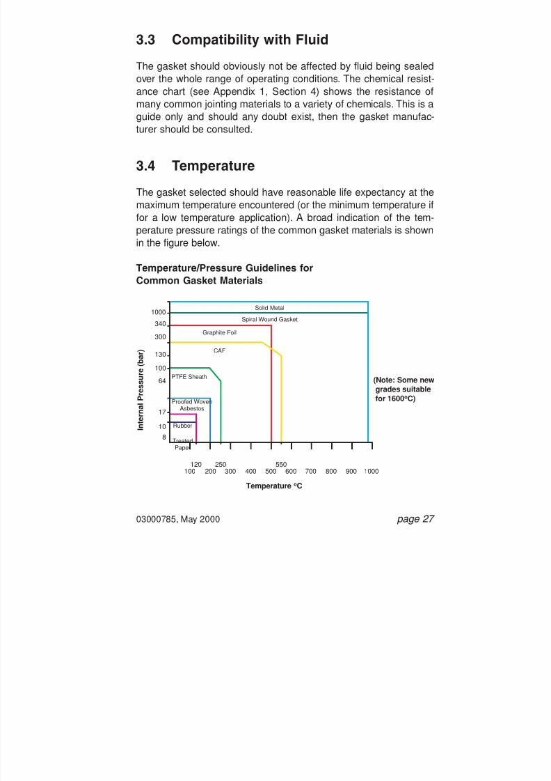
7/28/2019 117758036 Pipefitter Handbook
http://slidepdf.com/reader/full/117758036-pipefitter-handbook 29/161
3.3 Compatibility with Fluid
The gasket should obviously not be affected by fluid being sealedover the whole range of operating conditions. The chemical resist-
ance chart (see Appendix 1, Section 4) shows the resistance ofmany common jointing materials to a variety of chemicals. This is aguide only and should any doubt exist, then the gasket manufac-turer should be consulted.
3.4 Temperature
The gasket selected should have reasonable life expectancy at themaximum temperature encountered (or the minimum temperature iffor a low temperature application). A broad indication of the tem-perature pressure ratings of the common gasket materials is shownin the figure below.
Temperature/Pressure Guidelines forCommon Gasket Materials
03000785, May 2000 page 27
100
8 TreatedPaper
Proofed WovenAsbestos
PTFE Sheath
CAF
Graphite Foil
Spiral Wound Gasket
Solid Metal
Rubber
120200 300 400 500 600 700 800 900 1000
10
17
64
100
130
300
340
1000
250 550
I n t e r n a l P r e s s u r e
( b a r )
Temperature oC
(Note: Some newgrades suitablefor 1600 oC)

7/28/2019 117758036 Pipefitter Handbook
http://slidepdf.com/reader/full/117758036-pipefitter-handbook 30/161
Gasket materials are designed to compress under load to achievethe initial seal. However, to retain that seal, the gasket should beable to resist flow (or creep) to prevent loss of surface stress by boltreduction. This property is very important and is the one that mostreadily separates high quality from low quality gaskets.
Under ambient temperature conditions, most gasket materials donot creep significantly, but as the temperature rises beyond 100°C,creep becomes a serious consideration.
For all applications but particularly for low temperature applications,the following points should be observed:
• The gasket should be completely dry when installed (gaskets forsuch applications should be stored in a dry atmosphere).
• The required flange loading should be applied at ambient tem-perature.
Notes :
1. The above information is intended as a guide to the maximumpossible ratings of each class of jointing. It does not imply thatall the gaskets within each generic type are suitable for thetemperatures and pressures shown.
2. Even if the material chosen is theoretically suitable for the tem-
perature and pressure, other factors should be consideredsuch as available bolting, flange facing type, shock loadings,etc.
3. Consultation with gasket experts should take place at thedesign stage to ensure that the gasket selected is suitable forall conditions of the application.
page 28 03000785, May 2000

7/28/2019 117758036 Pipefitter Handbook
http://slidepdf.com/reader/full/117758036-pipefitter-handbook 31/161
3.5 Internal Pressure
The gasket has to be suitable for the maximum internal pressureexperienced; this is often the test pressure, which can be > 2 times
the flange rating at ambient temperature.
Vacuum conditions need special considerations but as a guide:
• For coarse vacuum (760 torr to 1 torr): flat rubber or compressedasbestos fibre gaskets.
• For high vacuum (1 torr to 1x10 -7 torr): rubber ‘O’ rings ormoulded rectangular seals.
• For very high vacuum (below 1x10 -7 torr): specialised sealsrequired.
3.6 Special Considerations
There are many factors apart from those already considered thataffect the selection of the correct gasket material and type.
• Cycling conditions.
• If the service conditions include frequent thermal or pressurecycles, then the gasket has to be resilient enough to allow for the
flange movements and strong enough to resist the mechanicalloading.
a) VibrationIf the pipeline is subjected to undue vibration, then the gaskethas to withstand the mechanical effects involved.
b) Erosive MediaCertain media (e.g. solids suspended in liquids) can slowlyerode gaskets leading to a much shorter life than expected. In
03000785, May 2000 page 29
7/28/2019 117758036 Pipefitter Handbook
http://slidepdf.com/reader/full/117758036-pipefitter-handbook 32/161
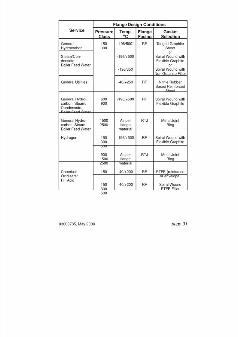
7/28/2019 117758036 Pipefitter Handbook
http://slidepdf.com/reader/full/117758036-pipefitter-handbook 33/161
03000785, May 2000 page 31
ServiceFlange Design Conditions
PressureClass
GasketSelection
FlangeFacing
Temp.oC
GeneralHydrocarbon
Steam/Con-densate,Boiler Feed Water
General Utilities
General Hydro-carbon, Steam/ Condensate,Boiler Feed Water
General Hydro-carbon, Steam,Boiler Feed Water
Hydrogen
ChemicalOxidisers/ HF Acid
-196/500*
-196/+500
-196/350
-40/+250
-196/+500
As perflange
material
-196/+500
As perflange
material-40/+200
-40/+200
150300
600900
15002500
150300600
9001500
2500150
150300600
RF
RF
RF
RTJ
RF
RTJ
RF
RF
Tanged GraphiteSheet
orSpiral Wound withFlexible Graphite
orSpiral Wound withNon Graphite Filter
Nitrile RubberBased Reinforced
Sheet
Spiral Wound withFlexible Graphite
Metal JointRing
Spiral Wound withFlexible Graphite
Metal JointRing
PTFE (reinforcedor envelope)
Spiral WoundPTFE Filler
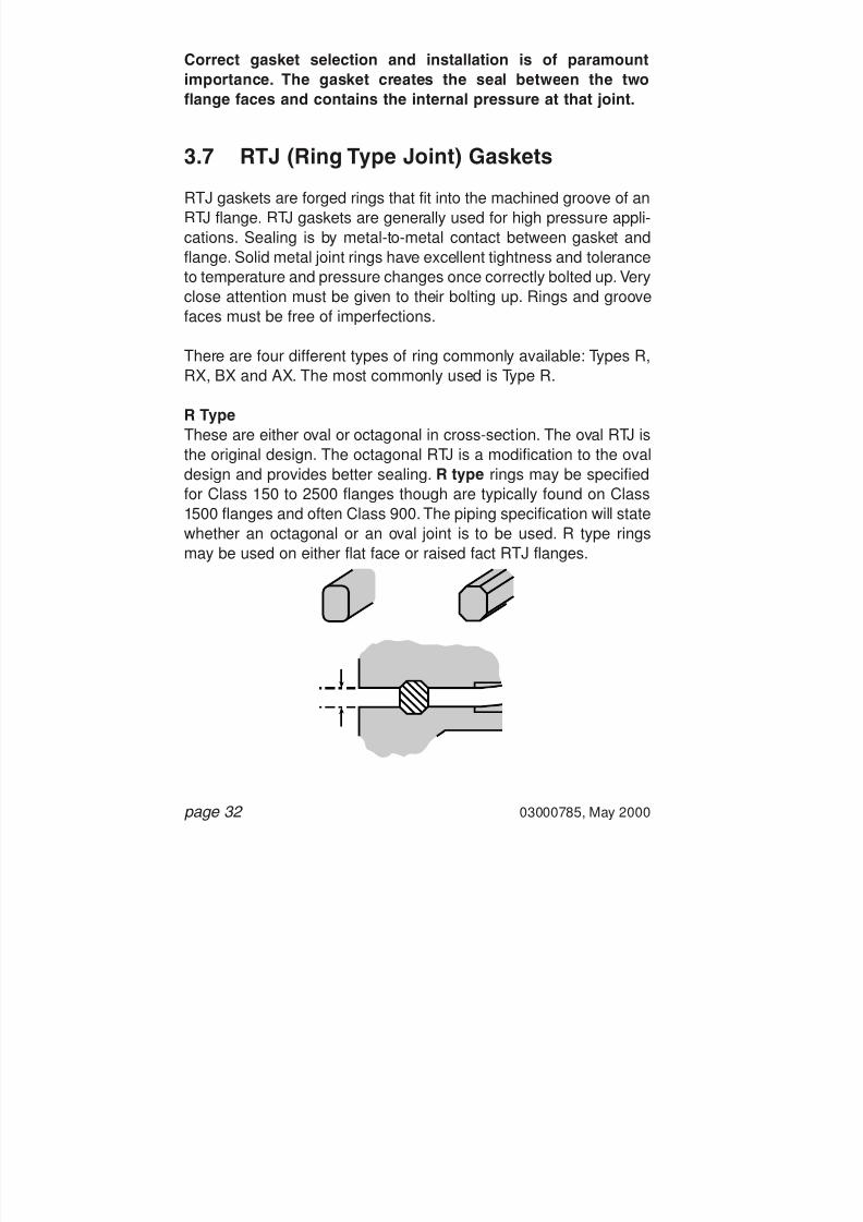
7/28/2019 117758036 Pipefitter Handbook
http://slidepdf.com/reader/full/117758036-pipefitter-handbook 34/161
Correct gasket selection and installation is of paramountimportance. The gasket creates the seal between the twoflange faces and contains the internal pressure at that joint.
3.7 RTJ (Ring Type Joint) Gaskets
RTJ gaskets are forged rings that fit into the machined groove of anRTJ flange. RTJ gaskets are generally used for high pressure appli-cations. Sealing is by metal-to-metal contact between gasket andflange. Solid metal joint rings have excellent tightness and toleranceto temperature and pressure changes once correctly bolted up. Very
close attention must be given to their bolting up. Rings and groovefaces must be free of imperfections.
There are four different types of ring commonly available: Types R,RX, BX and AX. The most commonly used is Type R.
R TypeThese are either oval or octagonal in cross-section. The oval RTJ isthe original design. The octagonal RTJ is a modification to the ovaldesign and provides better sealing. R type rings may be specifiedfor Class 150 to 2500 flanges though are typically found on Class1500 flanges and often Class 900. The piping specification will statewhether an octagonal or an oval joint is to be used. R type ringsmay be used on either flat face or raised fact RTJ flanges.
page 32 03000785, May 2000

7/28/2019 117758036 Pipefitter Handbook
http://slidepdf.com/reader/full/117758036-pipefitter-handbook 35/161
RX TypeRX gaskets fit and seal into the same groove sizes as do R typegaskets. Note that the RX gasket is wider than the R type gasketand the flange face-to-face separation will therefore be greater.
RX gaskets are normally specified up to Class 5000 API 6A Type Bflanges. They are used when a more effective seal is required whichis resistant to vibrations, shock loadings, etc., for example, on well-heads and Christmas trees.
The asymmetric cross-section makes the gasket self-energising.The outside bevel of the ring makes the initial contact with the
grooves of the flange and thus preloads the gasket against thegroove outer surface.
BX TypeThese are only used on API 6A Type BX flanges and are rated fromClass 5000 to 15000.
The pitch diameter of the ring is slightly greater than the pitch diam-eter of the flange groove. This preloads the gasket and creates apressure energised sea.
Type BX gaskets are NOT inter-changeable with R or RX gaskets.The groove on a flange which accommodates a BX gasket isdimensionally different to that for R and RX gaskets.
03000785, May 2000 page 33

7/28/2019 117758036 Pipefitter Handbook
http://slidepdf.com/reader/full/117758036-pipefitter-handbook 36/161
When correctly fitted, the flange face-to-face separation using a BXgasket is zero.
Note : It is particularly important to check the flange face-to-faceseparation which must be uniform around the entire circumferenceof the flange. RTJ flanged joints are particularly susceptible touneven bolt tensioning and misalignment of the ring within thegroove.
RTJ Gasket Identification and Specification
a) Type: Whether R, RX or BX. If R, state whether octagonal oroval. The type of ring to be used will be specified in the pipingspecification.
b) Ring Number: For example R46 will fit a 6 inch NB Class 1500RTJ flange.
c) Material: A variety of materials is available. Again check withthe piping specification for the correct material. The materialgrade will have an identifying code. For example:
Soft Iron: DStainless Steel 316 : S316
page 34 03000785, May 2000
0

7/28/2019 117758036 Pipefitter Handbook
http://slidepdf.com/reader/full/117758036-pipefitter-handbook 37/161
d) Standard: Either ANSI B16.20 or API 6A; as specified in thepiping specification (these two standards are equivalent andinterchangeable).
e) Identification: The type, ring number and material will alwaysbe marked on the side of the ring.
03000785, May 2000 page 35
Oval RTJ inOval Groove
Octagonal RTJ inOctagonal Groove
Oval RTJ inOctagonal Groove

7/28/2019 117758036 Pipefitter Handbook
http://slidepdf.com/reader/full/117758036-pipefitter-handbook 38/161
3.8 Spiral Wound Gaskets
The standard of SW gaskets can vary considerably between man-ufacturers, and they should be obtained only from reputable sup-
pliers.
Most Spiral Wound Gaskets now being used are Spiral Wound 316st/st Windings and Graphite Filler. These gaskets have a 316 st/stinner ring and coated carbon steel outer guide ring, but on someoccasions the outer ring could be stainless steel to provide corro-sion resistance to the external environment.
page 36 03000785, May 2000
Gasket NominalThickness
Recommended CompressedThickness
3.2 mm
4.5 mm
6.4 mm
7.2 mm
2.3 - 2.5 mm
3.2 - 3.4 mm
4.6 - 4.9 mm
4.8 - 5.0 mm
316 STAINLESSSTEEL WINDINGS
316 STAINLESSSTEEL INNER
GRAPHITEFILLER
CARBON STEELOUTER

7/28/2019 117758036 Pipefitter Handbook
http://slidepdf.com/reader/full/117758036-pipefitter-handbook 39/161
These gaskets are fitted with an internal guide ring which:
• Provides an additional compression stop.• Restricts the lateral flow of the gaskets toward the bore.• Acts as a heat and corrosion barrier protecting the gasket and
flange.
By filling the annular space between the gasket and flange, itreduces turbulent flow of the fluid or the possibility of the accumu-lation of solids, and possible corrosion.
The piping specifications for each individual plant will be changedto accommodate the new gaskets. The stores Vocab numbers willremain the same for the equivalent size spiral wound type.
Spiral Wound Gaskets that may be present in flanges:
Spiral wound gaskets are typically used on intermediate pressuresystems and will be found on Class 300 flanges, Class 600 andClass 900 flanges.
03000785, May 2000 page 37
Filler Materials Temperature LimitsSpecial Canadian Asbestos
PTFE
Graphite
Ceramic
550 oC
260 oC
550 oC
800 oC
Flange Surface Finish Micro Meter
General
Critical
Vacuum
3.2 - 5.1
3.2
2.0
7/28/2019 117758036 Pipefitter Handbook
http://slidepdf.com/reader/full/117758036-pipefitter-handbook 40/161

7/28/2019 117758036 Pipefitter Handbook
http://slidepdf.com/reader/full/117758036-pipefitter-handbook 41/161
Note that the spiral windings should never be exposed to the flowof the process fluids. The ID of the inner ring should be flush withthe bore of the flange and this should be checked prior to bolting up.
3.8.3 Outer Metal Ring
The outer metal ring acts as a compression stop and an anti-blowout device. It also centres the gasket on the flange face.
The spiral wound gasket should be centred on the flange with theouter ring resting against the studbolts. If this is not the case, theincorrect gasket has been chosen and should be changed.
3.8.4 Filler Material
For most applications in the petro-chemical industry, an asbestosfiller was usually specified. Asbestos is hazardous to health andeven though trapped within the spiral winding, SW gasketsshould be handled with care. Full procedures are available andshould be consulted. Piping specifications now quote a non-asbestos filler instead of asbestos. Graphite filler has nowtaken over as being the preferred filler material.
For special applications other materials are available, such asgraphite and ceramic fillers.
03000785, May 2000 page 39

7/28/2019 117758036 Pipefitter Handbook
http://slidepdf.com/reader/full/117758036-pipefitter-handbook 42/161
3.8.5 Spiral Wound Gasket Specification and Identification
Spiral wound gaskets are supplied and identified as follows:
a) NPS and Flange Pressure Class: A class and nominal pipesize must be specified and must match that of the flange con-cerned. The class and size of the gasket will always be stampedon the outer ring.
b) Flange Type: Spiral wound gaskets are normally used onRFWN flanges. If used on SO flanges, this should be stated asspecial gasket sizes will be required for NPS up to 1 1 / 2 inches.
c) Filler Material: A variety of materials is available. Normallyasbestos was used but now graphite, PTFE, ceramic fillers, etc.are used predominantly. The filler material will be specified inthe piping specification. Identification is by way of a colour codeon the spiral wound section.
d) Winding Material: Winding material is important as it shouldbe resistant to the process conditions. The winding material willbe specified in the piping specification and is typically stainlesssteel. Identification is by a colour code on the outer ring.
e) Inner Ring: The inner ring will normally be the same materialgrade as the metal winding as it must equally resist the processconditions. Material grade will be specified in the piping speci-
fication.
f) Outer Ring: Not such a critical parameter as the inner ring asit does not come into contact with process fluids. It is normallycarbon steel and again will be specified in the piping specifica-tion.
g) Standard: Usually ASME B16.20, BS 3381 or API 601.
page 40 03000785, May 2000

7/28/2019 117758036 Pipefitter Handbook
http://slidepdf.com/reader/full/117758036-pipefitter-handbook 43/161
03000785, May 2000 page 41
3.8.6 Spiral Wound Gasket Colour Code Reference Chart
Warning:There are some process applications where graphite is unsuit-able. Refer to manufacturer s data sheets for details.
Winding Material Colour Code
The outer ring of the SW gasket will be coloured to identify thewinding material. The ring may be only coloured on the outer edge.
Carbon Steel Silver
304SS Yellow316SS Green347SS Blue321SS TurquoiseMonel OrangeNickel 200 RedTitanium PurpleAlloy 20 BlackHastalloy B BrownHastalloy C BeigeInc 600 GoldIncoloy White
Filler Material Colour Code
The spiral wound section of the SW gasket will be coloured to iden-tify the filler material, with flashes around the outer ring of the rele-vant colour.
Non-Asbestos PinkGraphite GreyAsbestos NonePTFE WhiteCeramic Light Green

7/28/2019 117758036 Pipefitter Handbook
http://slidepdf.com/reader/full/117758036-pipefitter-handbook 44/161
Note that the above colour coding is based on API 601.
When inspecting gaskets already fitted to flanges, it can bedifficult to distinguish between white grey and light green.Users must be aware of this problem.
3.8.7 Spiral Wound Gasket in its Uncompressed State
page 42 03000785, May 2000
EXTERNAL RING INTERNAL RING
INNER RING ID
GASKET ID
GASKET OD
GUIDE RING OD
Joint in its Uncompressed State
Cross-Section through a Gasket

7/28/2019 117758036 Pipefitter Handbook
http://slidepdf.com/reader/full/117758036-pipefitter-handbook 45/161
3.8.8 Surface Finish Values for Flange Facings
(Amends ANSI B16.5, 6.3.4.10)(All dimensions in mm)
3.9 Sheet Gaskets
Non-Asbestos Fibre (NAF) gaskets have now replacedCompressed Asbestos Fibre (CAF) gaskets.
They are used for low pressure applications and are typically foundon Class 150 and Class 300 flanges. They are normally used onRaised Face flanges (self-centering flat ring type gasket), but arealso used on Flat Face flanges (full face type gaskets are required).
3.9.1 Tanged Graphite Gaskets
Previously the predominant gasket used in BP Amoco has beenCompressed Asbestos Fibre (CAF). This material covers a widerange of applications, but has a known health risk.
03000785, May 2000 page 43
FlangeRatingClass
150
300 -2500
ALL
0.05
0.015
-
1.6
0.8
-
0.8
0.3
-
12.5
12.5
12.5
3.2
3.2
3.2
12.75
6.3
6.3
50
25
25
Turning †
Turning†
Other thanTurning
† The term "Turning" includes any method of machine operation producingeither serrated concentric or serrated spiral grooves machined with a roundnosed tool.
Methodof
Machining
Depthof
Serr.
Pitchof
Serr.Min.mm
Max.mm
Min.mm
Max.mm
Rz
(Ref. Std. ISO 468)
RaRadius
ofTool

7/28/2019 117758036 Pipefitter Handbook
http://slidepdf.com/reader/full/117758036-pipefitter-handbook 46/161

7/28/2019 117758036 Pipefitter Handbook
http://slidepdf.com/reader/full/117758036-pipefitter-handbook 47/161
3.9.2 Utility Gaskets
In utility non-hydrocarbon services up to Class 300, where the tem-perature is below 100 oC, and in equipment blinding applications,high performance nitrile rubber based reinforced sheet containingnon-respirable glass fibres should be used.
3.9.3 Flat Rubber Gaskets
Flat rubber gaskets are normally found in the least hazardous andaggressive of conditions such as low pressure water services.Rubber gaskets are limited in use by temperature, pressure and
chemical resistance. They are also liable to creep, e.g. if subjectedto excessive bolt loading or repeated hydrotest.
Rubber gaskets are usually full face and are used on flat faceflanges. Of the variety of rubbers available, that most commonlyused as a gasket is neoprene. Other rubber materials includenatural rubber, Viton and Nitrile.
Rubber Gasket Specification and Identification
a) NPS and Flange Pressure Class: Always to be quoted. Itshould be marked on the gasket. If not, check the correct fit ofthe gasket on the flange.
Alternatively, the gasket may be cut from rubber sheet. The boreof the pipe must not be restricted by the gasket and the entireface of the flange must be covered.
Check the thickness of the gasket by reference to the pipingspecification.
b) Material: Whether neoprene, nitrile, etc., refer to the piping
specification.
03000785, May 2000 page 45

7/28/2019 117758036 Pipefitter Handbook
http://slidepdf.com/reader/full/117758036-pipefitter-handbook 48/161
NOW NOT IN USE (FOR INFORMATION ONLY)
3.10 Compressed Asbestos Fibre Gasket (CAF)
CAF gaskets were used for low pressure applications and were typ-ically found on Class 150 and Class 300 flanges, and will probablystill be in many flange applications.
CAF gaskets were normally used on Raised Face flanges (self-cen-tering flat ring type gasket), but may also have been used on FlatFace flanges (full face type gaskets are required).
Though of apparently simple design, the CAF gasket should betreated with equal respect as with all gaskets to ensure effectivesealing.
CAF gaskets are manufactured from asbestos fibres bonded in anitrile rubber compound. Sealing is by a similar mechanism to thespiral wound gaskets where the gasket material is soft enough toflow into the phonographic groove on the flange face when com-pressed. Correct gasket thickness is therefore important.
The surface finish on RF flanges used with CAF gaskets will be rel-atively coarse compared to that for SW gaskets. The requiredsurface finish will be as stated in the relevant section on Class 150flanges.
The gasket may or may not be coated with graphite. The graphitehas non-stick properties and enables the easy removal of thegasket when a flange is split. Graphite coated CAF gasketsSHOULD NOT be used in the following instances:
a) Austenitic stainless steel flanges on water duties.b) Aggressive water duty (e.g. cement lined pipework).c) Duties where temperatures exceed 450 degrees C.
page 46 03000785, May 2000

7/28/2019 117758036 Pipefitter Handbook
http://slidepdf.com/reader/full/117758036-pipefitter-handbook 49/161
Remember that CAF gaskets contain asbestos and should there-fore be handled carefully. If shaping a CAF gasket, do so by cutting,shearing or punching - NOT by sawing, grinding or drilling. Ifremoving an old CAF gasket from a flange, wet the gasket withwater to absorb any asbestos dust that may be freed, especially ifthe flange has to be scraped clean. Loose CAF waste should bedisposed of in sealed polythene bags and labelled as containingasbestos with an “asbestos warning” tag. Full procedures are avail-able and should be consulted.
CAF Gasket Specification and Identification
a) NPS and Flange Pressure Class: Always to be specified. Theinformation should also be marked on the gasket.
If not, check the correct fit of the gasket on the flange. It shouldbe centred when resting on the studbolts and the bore of thepipe should not be constricted. Alternatively the gasket may bea full face type, sized to the OD of the flange, particularly forsmall bore (less than 2 inch NB) pipework.
Check the thickness of the gasket. It will be quoted in the pipingspecification.
b) Gasket Coating: i.e. whether graphited or non-graphited. Thepiping specification should be consulted.
c) Standard: Normally BS 1832 or BS 2815 will be specified.
3.11 Gaskets for Lined Pipework
Joints in lined pipework are invariably flanged and gaskets oftenneed to create a seal despite many of the linings being of a softnature. Correct gasket selection is particularly important since:
03000785, May 2000 page 47

7/28/2019 117758036 Pipefitter Handbook
http://slidepdf.com/reader/full/117758036-pipefitter-handbook 50/161
page 48 03000785, May 2000
• Many linings, whilst having a smooth finish, have undulating sur-faces on the flanges due to the method of manufacture (e.g.glass).
• There is usually a good reason for using lined pipework (e.g.chemically aggressive fluid or pharmaceutical fluid) and thegasket often has to be equal to the lining in terms of chemicalresistance and freedom from contamination.
• Linings tend to be of a fragile nature and bolt loads have to bekept low to prevent damage. This limits the choice of gasketmaterial.
• The gasket material has often to withstand the effects of aggres-sive cleaning fluids as well as the service fluids.
Types of Linings Available
Rubber Lined:A soft rubber gasket can be applied. A steel or ebonite spacer canbe used to prevent over-compression.
Plastic Lined:Gaskets are not normally required, but there are exceptions:• where there are dissimilar flange connections (e.g. pipe to valve);• where the lining is too undulating;
• where the lining is applied via a dripping process, e.g. PVC.
Lead Lined:Creep resistant PTFE or a PTFE envelope with soft rubber insertcan be used.
Glass Lined:PTFE.

7/28/2019 117758036 Pipefitter Handbook
http://slidepdf.com/reader/full/117758036-pipefitter-handbook 51/161
03000785, May 2000 page 49
3.12 Gaskets - Do s and Don ts
Do s
a) Check the type, class, size and material specification of thegasket before using it. Check with the piping specification toconfirm that it is correct. Only use gaskets with non-asbestosmaterials.
b) Check the gasket for damage, nicks, etc. Ensure that it is cleanand free from any contaminants before use.
c) Ensure that the gasket fits correctly.
d) Check the flange face-to-face separation once the gasket hasbeen installed and the bolts tensioned. A uniform separation isrequired. If not, the gasket could be locally crushed or deformedand will not seal properly.
e) Wire brush studs/bolts and nuts to remove any dirt on thethreads. Ensure that the nuts can run freely down the threadsbefore use. Coat the studs/bolts with a thin film of an approvedlubricant prior to installation.
f) Use pre-cut tanged reinforced sheet gaskets.
g) Wear gloves when handling tanged reinforced gaskets.
Don ts
a) Do not re-use old gaskets. For every joint being made up, a newgasket should be used.
b) Do not use a gasket that has no identification. It may appear tofit the flange but this is not a guarantee.

7/28/2019 117758036 Pipefitter Handbook
http://slidepdf.com/reader/full/117758036-pipefitter-handbook 52/161
page 50 03000785, May 2000
c) Do not cut or deform a gasket to fit a flange. If the gasketdoesn’t fit, the wrong one has been chosen.
d) Do not hand-cut tanged reinforced gasket sheet. Use pre-cutgaskets.

7/28/2019 117758036 Pipefitter Handbook
http://slidepdf.com/reader/full/117758036-pipefitter-handbook 53/161
4. Compact Flanged Joints
A variety of different joint designs fall under the category of compactflanges. Each design is unique to its manufacturer and subse-quently reference to the joint normally involves quoting the manu-facturer’s name or a trade name, for example Graylok, Destec,Taper-lok and so on.
Compact flanges are used where savings in weight, space or mate-rial cost (especially so with exotic materials) are an advantage.
It is important to be able to recognise the different types of compactflanges available and brief descriptions of some available typesfollow.
4.1 Taper-Lok
The Taper-lok flange employs a conical gasket which is wedged asthe joint is tightened, thereby sealing on both its inside and outsidesurfaces. As internal pressure increases, the tapered gasket isforced in between the mating flanges, thereby further tightening theseal. Because of the male/female configuration requiring more
parts, Taper-lok joints have not been widely used by BP Amoco.
03000785, May 2000 page 51

7/28/2019 117758036 Pipefitter Handbook
http://slidepdf.com/reader/full/117758036-pipefitter-handbook 54/161
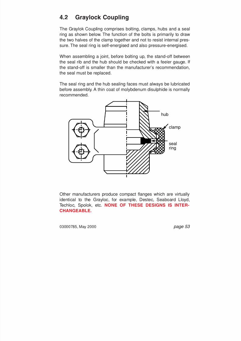
7/28/2019 117758036 Pipefitter Handbook
http://slidepdf.com/reader/full/117758036-pipefitter-handbook 55/161
4.2 Graylock Coupling
The Graylok Coupling comprises bolting, clamps, hubs and a sealring as shown below. The function of the bolts is primarily to draw
the two halves of the clamp together and not to resist internal pres-sure. The seal ring is self-energised and also pressure-energised.
When assembling a joint, before bolting up, the stand-off betweenthe seal rib and the hub should be checked with a feeler gauge. Ifthe stand-off is smaller than the manufacturer’s recommendation,the seal must be replaced.
The seal ring and the hub sealing faces must always be lubricatedbefore assembly. A thin coat of molybdenum disulphide is normallyrecommended.
Other manufacturers produce compact flanges which are virtuallyidentical to the Grayloc, for example, Destec, Seaboard Lloyd,Techloc, Spolok, etc. NONE OF THESE DESIGNS IS INTER-CHANGEABLE.
03000785, May 2000 page 53
hub
sealring
clamp

7/28/2019 117758036 Pipefitter Handbook
http://slidepdf.com/reader/full/117758036-pipefitter-handbook 56/161
4.3 Other Designs
There are a number of other compact flange designs, some ofwhich are either no longer manufactured or for which the manufac-
turers have ceased to exist. The following diagrams illustrate a fewsuch designs.
page 54 03000785, May 2000

7/28/2019 117758036 Pipefitter Handbook
http://slidepdf.com/reader/full/117758036-pipefitter-handbook 57/161
4.4 Compact Flanges Specification andIdentification
a) NPS and Flange Pressure Class: Some compact flanges useANSI B16.5 pressure ratings such as Class 600, 900, 1500, etc.Others require a design pressure to be specified.
b) Pipe Schedule: As specified in the pipe specification.
c) Material: Refer to the piping specification which will detail thematerial grade of the different components of the compact
flange. Also obtain the manufacturer’s product data which willinterpret any abbreviations for material grade that may bestamped on the components.
d) Manufacturer s Name/Trade Name/Model Number: A modelnumber may also be required for a particular compact flangedesign. Check with the manufacturer’s product data. This isthen sufficient to specify all the different components of thecompact flange: the seal ring, clamps, hubs, even the studbolts.The components will all be unique to the one manufacturer.
4.5 Compact Flanges - Do s and Don ts
Do sa) Follow the manufacturer’s installation procedures. Each proce-
dure will be different so it is important to use the correct one.
b) When assembling compact flanges that consist of two clamps,such as Grayloc, always align the clamps such that they sit tothe left and to the right of the pipe as opposed to top and
bottom. This prevents water from collecting in the clamps.
03000785, May 2000 page 55

7/28/2019 117758036 Pipefitter Handbook
http://slidepdf.com/reader/full/117758036-pipefitter-handbook 58/161
c) Many manufacturers state that their gaskets may be re-used.Always inspect a gasket for damage, deformation and wearbefore re-using it.
d) Follow the manufacturer’s disassembly procedures. Compactflange designs which include hubs, clamps and pressure ener-gised seal rings such as Grayloc and Seaboard Lloyd Clamplokshould be disassembled with care. Such designs can continueto contain residual pressure even with the studbolts removed,due to the wedging action of the clamp halves.
Always slacken the compact flange bolting and physically
dislodge the clamp halves as a safeguard against anytrapped residual pressure. Only then should bolting befully removed and the flange disassembled.
Don ts
a) Never mix and attempt to match parts of different compactflanges. They may look the same but none are interchangeable.Only use the parts from the specified flange manufacturer.
4.6 Breaking Joints
a) Before starting, check that your permit to work is valid
for the job in hand, and that the right protective clothing/ equipment is worn.
b) Confirm that the line has been drained/vented or iso-lated as appropriate before attempting to break a joint.
c) Ensure that the correct tools for the job are availableand are used.
page 56 03000785, May 2000

7/28/2019 117758036 Pipefitter Handbook
http://slidepdf.com/reader/full/117758036-pipefitter-handbook 59/161
d) When attempting to break a joint, avoid standingdirectly alongside or underneath the joint. Always breakthe bolt that is furthest away from you first, preferablythe bottom furthest bolt.
e) Continually check for leakage, seepage or signs ofpressure in the line - a hissing sound, a smell of gas,etc. Use a pair of wedges away from you to determinethis.
03000785, May 2000 page 57
BEFORE PARTINGA JOINT, ASSESS
THE FORCES INTHE PIPE.

7/28/2019 117758036 Pipefitter Handbook
http://slidepdf.com/reader/full/117758036-pipefitter-handbook 60/161
f) If at any stage there is a sign of pressure in the line,stop work immediately. Re-tighten the joint tocontain the leak and then report the situation toyour supervisor. The line isolation will have to bechecked.
g) Never remove nuts from the studs until you have ascer-tained that the pipework is empty.
h) If a blank or a spade is being removed, or a spectacleblind is being swung, check the weight from the tables.If necessary, support with a chain block before any
work continues. Ensure the spectacle is clean and freefrom rust before releasing the studbolts.
i) Before finally parting a joint, always assess the forceson the pipe. Will the pipework spring apart? Is one halfof the joint unsupported? Temporary supports may beneeded.
4.7 Making Joints
a) Before starting, check that your permit to work is validfor the job in hand, and that the right protective clothing/ equipment is worn.
b) Check if there is a procedure in place for carrying outthe intended work - and if so follow the procedure.
c) Determine the type, size and class of the flange to bebolted. Determine the piping specification number ofthe pipework. Check the material, coating and size ofthe studbolts. Check the type, pressure rating and sizeof the gasket. The studbolts and gasket specificationsfor the flanged joint must always match the descriptionsin the piping specification document.
page 58 03000785, May 2000

7/28/2019 117758036 Pipefitter Handbook
http://slidepdf.com/reader/full/117758036-pipefitter-handbook 61/161
d) Only use the correct materials for the job. Never usedamaged materials and always use a new gasketwhen making up a joint.
e) If using a “cut from sheet ” gasket, ensure that the boltholes and edges are flat with no burrs or ridges asthese will result in uneven stress loading and maycause a leak.
f) Ensure that the correct tools for the job are availableand are used.
g) Ensure the joint faces are clean before inserting joint.
h) Visually check the flanges for equal gap. If a larger gapappears on one side of the flange, tighten the boltwhich corresponds with the larger gap first.
i) Ensure the flanges are parallel after tightening.
j) Attach any QA Tags to the flange when applicable.
03000785, May 2000 page 59

7/28/2019 117758036 Pipefitter Handbook
http://slidepdf.com/reader/full/117758036-pipefitter-handbook 62/161
This page left intentionally blank.
page 60 03000785, May 2000
7/28/2019 117758036 Pipefitter Handbook
http://slidepdf.com/reader/full/117758036-pipefitter-handbook 63/161
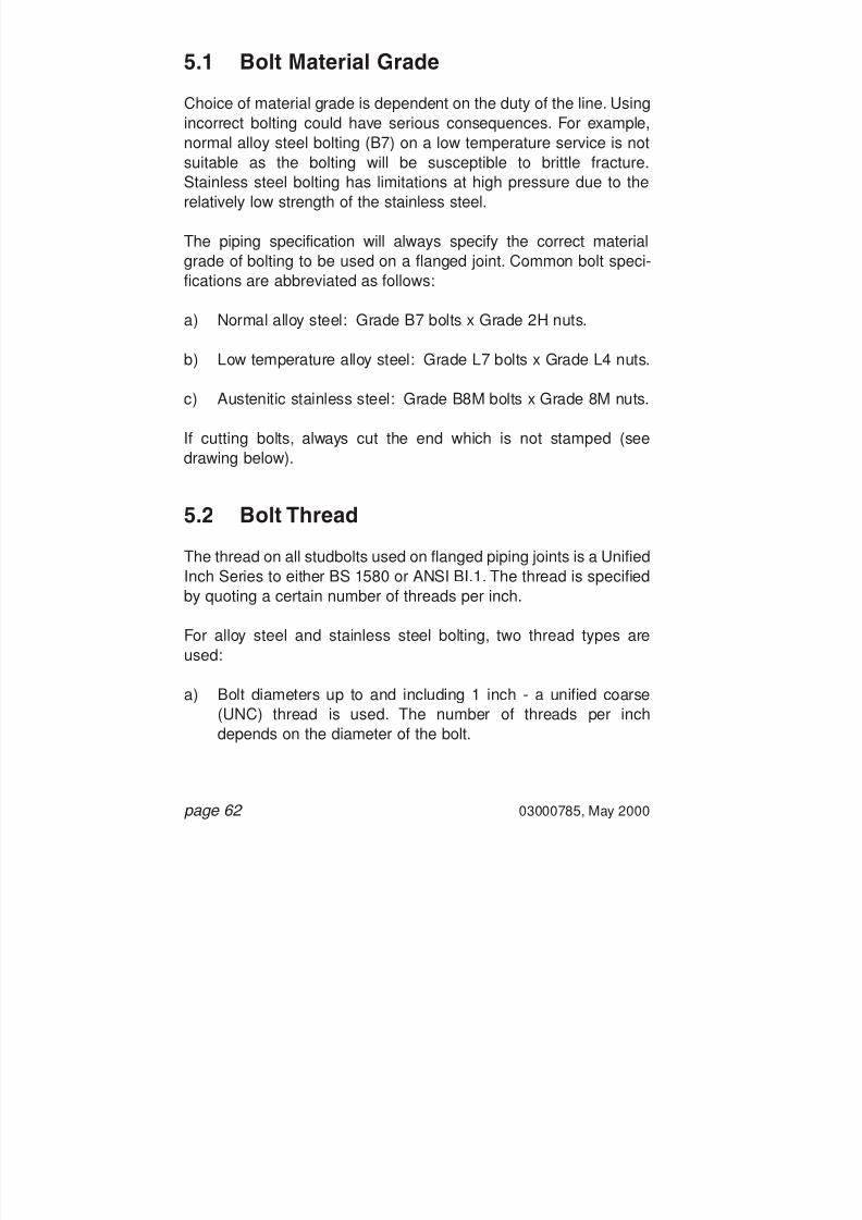
7/28/2019 117758036 Pipefitter Handbook
http://slidepdf.com/reader/full/117758036-pipefitter-handbook 64/161
5.1 Bolt Material Grade
Choice of material grade is dependent on the duty of the line. Usingincorrect bolting could have serious consequences. For example,
normal alloy steel bolting (B7) on a low temperature service is notsuitable as the bolting will be susceptible to brittle fracture.Stainless steel bolting has limitations at high pressure due to therelatively low strength of the stainless steel.
The piping specification will always specify the correct materialgrade of bolting to be used on a flanged joint. Common bolt speci-fications are abbreviated as follows:
a) Normal alloy steel: Grade B7 bolts x Grade 2H nuts.
b) Low temperature alloy steel: Grade L7 bolts x Grade L4 nuts.
c) Austenitic stainless steel: Grade B8M bolts x Grade 8M nuts.
If cutting bolts, always cut the end which is not stamped (seedrawing below).
5.2 Bolt Thread
The thread on all studbolts used on flanged piping joints is a UnifiedInch Series to either BS 1580 or ANSI BI.1. The thread is specified
by quoting a certain number of threads per inch.
For alloy steel and stainless steel bolting, two thread types areused:
a) Bolt diameters up to and including 1 inch - a unified coarse(UNC) thread is used. The number of threads per inchdepends on the diameter of the bolt.
page 62 03000785, May 2000

7/28/2019 117758036 Pipefitter Handbook
http://slidepdf.com/reader/full/117758036-pipefitter-handbook 65/161

7/28/2019 117758036 Pipefitter Handbook
http://slidepdf.com/reader/full/117758036-pipefitter-handbook 66/161
alloy steel bolting and that hot dipped spun galvanised bolting hasprovided better corrosion protection at reduced cost.
Bolts can be supplied with a variety of surface treatments. Thecommon options are:
Note that bolts with different coatings require different torquevalues to achieve the same bolt tension. It is therefore important notto mix studbolts with different coatings on a given flange, as it willbe difficult to achieve a uniform bolt tension on all the studbolts. Fullprocedures are available on bolt tightening and should be con-
sulted.
A Note of Warning: Cadmium plated components give off toxicfumes when heated to sufficiently high temperatures. Therefore,heat should not be applied to release tight bolts. Furthermore,gloves should be worn when handling cadmium plated componentsto prevent skin abrasions.
page 64 03000785, May 2000
Type StandardMinimumThickness
Zinc and Cadmium Electroplate
PTFE Coating + Phosphate
PTFE Coating + Electroplate(Zn or Cd)
Sheradising (Barrelled in HotZinc Dust)
Spun Galvanised (Dipped inMolten Zinc)
BS 1706
-
-
BS 4921Class 1/2
BS 729
8 mm
30 mm PTFE
30 mm PTFE / 8 mm Zn/Cd
30 mm / 15 mm
43 mm

7/28/2019 117758036 Pipefitter Handbook
http://slidepdf.com/reader/full/117758036-pipefitter-handbook 67/161

7/28/2019 117758036 Pipefitter Handbook
http://slidepdf.com/reader/full/117758036-pipefitter-handbook 68/161

7/28/2019 117758036 Pipefitter Handbook
http://slidepdf.com/reader/full/117758036-pipefitter-handbook 69/161
The bolt consists of a standard industry bolt which is drilled at oneend along the axis to accept a headed pin and cap mechanismwhich acts as a mechanical strain gauge.
The drawing shows the arrangement: the headed pin is positivelyanchored to the base of the hole and retains a rotor and cap whichis free to spin in a pre-set air gap between the rotor and bolt face.
When tightening takes place, the stud begins to stretch (propor-tional to load) but the head pin does not, thus the air gap closes astightening continues to extend the bolt. When the air gap is fullyclosed, the rotor locks. The pre-set air gap is directly proportional to
the bolt extension (strain) and hence the stress in the bolt (and loadtransferred to the gasket joint). The user simply turns the cap byfinger and thumb while tightening the bolt until the cap locks.Continued tightening is unnecessary and simply over-compressesthe gasket and operates the bolt nearer to its yield point. Over-extension of the bolt does not damage the strain gauge mechanismsince the now locked rotor transfers load to the pin which then startsto extend with the bolt. When the load is removed, the pin returns toits original length along with the bolt (unless it has been over-stressed beyond yield).
Every Rotabolt is individually loaded in the factory in order to pre-set the air gap for the required load. The set load is then stampedon the end of the cap for easy identification.
Rotabolts are, however, much more expensive than standard boltingand should only be used where service duty is severe or previoushistory of joint leakage justifies. For example, the cost of continuallyFurmaniting a troublesome joint, together with the possible hydro-carbon losses and even unscheduled plant shutdowns, may easily
justify the added expense. Rotabolts have already been usedthroughout BP Amoco on troublesome heat exchangers andflanges.
03000785, May 2000 page 67
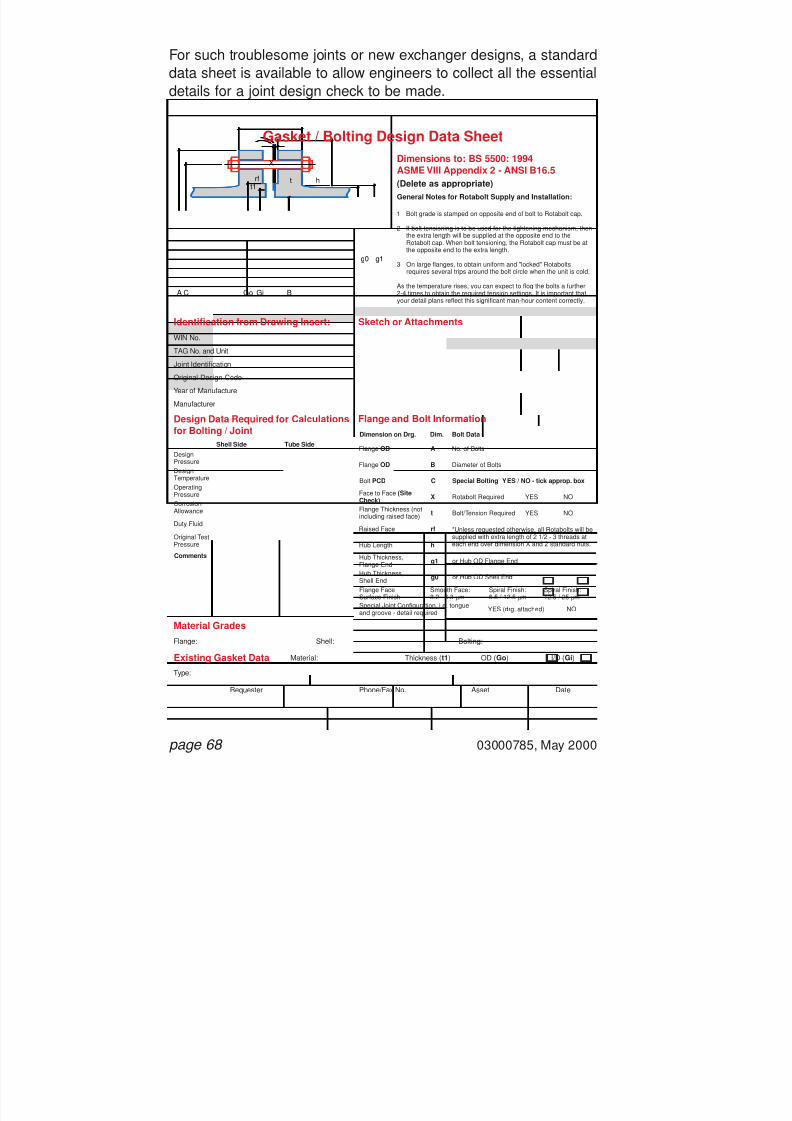
7/28/2019 117758036 Pipefitter Handbook
http://slidepdf.com/reader/full/117758036-pipefitter-handbook 70/161
For such troublesome joints or new exchanger designs, a standarddata sheet is available to allow engineers to collect all the essentialdetails for a joint design check to be made.
page 68 03000785, May 2000
GoCA Gi B
X
tt1
rf h
g0 g1
Gasket / Bolting Design Data SheetDimensions to: BS 5500: 1994ASME VIII Appendix 2 - ANSI B16.5
Identification from Drawing Insert:WIN No.
TAG No. and Unit
Joint Identification
Original Design Code
Year of Manufacture
Manufacturer
Flange:
Type:
DesignPressureDesignTemperatureOperatingPressureCorrosionAllowance
Duty Fluid
Original Test
Pressure
Flange OD No. of BoltsA
Flange OD Diameter of BoltsB
Raised Face *Unless requested otherwise, all Rotabolts will besupplied with extra length of 2 1/2 - 3 threads ateach end over dimension X and 2 standard nuts.
rf
Hub Length h
Face to Face (SiteCheck) Rotabolt RequiredX
Flange Thickness (notincluding raised face) Bolt/Tension Required
YES
YES
NO
NOt
Hub Thickness,Flange End or Hub OD Flange Endg1
Hub Thickness,Shell EndFlange FaceSurface FinishSpecial Joint Configuration, i.e. tongueand groove - detail required
Smooth Face:3.2 - 6.3 mm
Spiral Finish:6.5 / 12.5 mm
Spiral Finish:12.5 / 25 mm
or Hub OD Shell Endg0
Bolt PCD Special Bolting YES / NO - tick approp. boxC
Shell Side
Comments
Tube SideDimension on Drg. Dim. Bolt Data
Sketch or Attachments
Design Data Required for Calculationsfor Bolting / Joint
Material Grades
Flange and Bolt Information
(Delete as appropriate)General Notes for Rotabolt Supply and Installation:
1.
2.
3.
As the temperature rises, you can expect to flog the bolts a further2-4 times to obtain the required tension settings. It is important thatyour detail plans reflect this significant man-hour content correctly.
Bolt grade is stamped on opposite end of bolt to Rotabolt cap.
If bolt tensioning is to be used for the tightening mechanism, thenthe extra length will be supplied at the opposite end to theRotabolt cap. When bolt tensioning, the Rotabolt cap must be atthe opposite end to the extra length.
On large flanges, to obtain uniform and "locked" Rotabolts
requires several trips around the bolt circle when the unit is cold.
Existing Gasket Data
Shell:
Material: Thickness ( t1 ) OD ( Go ) I/D (Gi)
Phone/Fax No.Requester Asset Date
Bolting:
YES (drg. attached) NO

7/28/2019 117758036 Pipefitter Handbook
http://slidepdf.com/reader/full/117758036-pipefitter-handbook 71/161

7/28/2019 117758036 Pipefitter Handbook
http://slidepdf.com/reader/full/117758036-pipefitter-handbook 72/161
page 70 03000785, May 2000
5.6 Hydraulic Bolt Tensioning
High pressure flanges, large diameter flanges and flanges on haz-ardous services are often made up using Hydraulic Bolt Tensioners.
The Bolt Tensioners operate by hydraulically “stretching” thestudbolt to a pre-defined limit after which the operator is then ableto hand-tighten the nuts. The hydraulic load is then released and thestudbolt remains tensioned. The advantage of tensioning(stretching) against torquing is that the process is not dependent onthe type of lubrication used and eliminates the effect of frictionunder the nut and between threads. Accurate bolt tensions aretherefore obtained.
To pull down the flange evenly, several bolts can be tensioned at thesame time. All the studbolts will eventually be tensioned after suc-cessive “passes” of the bolt tensioning eqiupment.
Note that the use of the bolt tensioning equipment usually requiresthe studbolts to protrude past the nut by an additional bolt diameter.Obstructions such as pipe supports and instrument tappings mayprevent the bolt tensioning equipment from being fitted over thestudbolt. In such cases, hydraulic torque wrenches will then be usedto tension the bolts.
Hydraulic Bolt Tensioning is a specialised activity. Only trained per-sonnel carry out the bolt tensioning using equipment in good order.
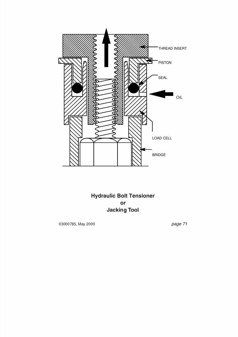
7/28/2019 117758036 Pipefitter Handbook
http://slidepdf.com/reader/full/117758036-pipefitter-handbook 73/161
03000785, May 2000 page 71
Hydraulic Bolt Tensioneror
Jacking Tool
,
,
,
,
,
,
,
,
,
,
,
,
,
,
,
,
,
,
,
,
,
,
,
,
,
,
,
,
,
,
,
,
,
,
,
,
,
,
,
,
,
,
,
,
,
,
,
,
,
,
,
,
,
,
,
,
,
,
,
,
,
,
,
,
,
,
,
,
,
,
,
,
,
,
,
,
,
,
,
,
,
,
,
,
,
,
,
,
,
,
,
,
,
,
,
,
,
,
,
,
,
,
,
,
,
,
,
,
,
,
,
,
,
,
,
,
,
,
,
,
,
,
,
,
,
,
,
,
,
,
,
,
,
,
,
,
,
,
,
,
,
,
,
,
,
,
,
,
,
,
,
,
,
,
,
,
,
,
,
,
,
,
,
,
,
,
,
,
,
,
,
,
,
,
,
,
,
,
,
,
,
,
,
,
,
,
,
,
,
,
,
,
,
,
,
,
,
,
,
,
,
,
,
,
,
,
,
,
,
,
,
,
,
,
,
,
,
,
,
,
,
,
,
,
,
,
,
,
,
,
,
,
,
,
,
,
,
,
,
,
,
,
,
,
,
,
,
,
,
,
,
,
,
,
,
,
,
,
,
,
,
,
,
,
,
,
,
,
,
,
,
,
,
,
,
,
,
,
,
,
,
,
,
,
,
,
,
,
,
,
,
,
,
,
,
,
,
,
,
,
,
,
,
,
,
,
,
,
,
,
,
,
,
,
,
,
,
,
,
,
,
,
,
,
,
,
,
,
,
,
,
,
,
,
,
,
,
,
,
,
,
,
,
,
,
,
,
,
,
,
,
,
,
,
,
,
,
,
,
,
,
,
,
,
,
,
,
,
,
,
,
,
,
,
,
,
,
,
,
,
,
,
,
,
,
,
,
,
,
,
,
,
,
,
,
,
,
,
,
,
,
,
,
,
,
,
,
,
,
,
,
,
,
,
,
,
,
,
,
,
,
,
,
,
,
,
,
,
,
,
,
,
,
,
,
,
,
,
,
,
,
,
,
,
,
,
,
,
,
,
,
,
,
,
,
,
,
,
,
,
,
,
,
,
,
,
,
,
,
,
,
,
,
,
,
,
,
,
,
,
,
,
,
,
,
,
,
,
,
,
,
,
,
,
,
,
,
,
,
,
,
,
,
,
,
,
,
,
,
,
,
,
,
,
,
,
,
,
,
,
,
,
,
,
,
,
,
,
,
,
,
,
,
,
,
,
,
,
,
,
,
,
,
,
,
,
,
,
,
,
,
,
,
,
,
,
,
,
,
,
,
,
,
,
,
,
,
,
,
,
,
,
,
,
,
,
,
,
,
,
,
,
,
,
,
,
,
,
,
,
,
,
,
,
,
,
,
,
,
,
,
,
,
,
,
,
,
,
,
,
,
,
,
,
,
,
,
,
,
,
,
,
,
,
,
,
,
,
,
,
,
,
,
,
,
,
,
,
,
,
,
,
,
,
,
,
,
,
,
,
,
,
,
,
,
,
,
,
,
,
,
,
,
,
,
,
,
,
,
,
,
,
,
,
,
,
,
,
,
,
,
,
,
,
,
,
,
,
,
,
,
,
,
,
,
,
,
,
,
,
,
,
,
,
,
,
,
,
,
,
,
,
,
,
,
,
,
,
,
,
,
,
,
,
,
,
,
,
,
,
,
,
,
,
,
,
,
,
,
,
,
,
,
,
,
,
,
,
,
,
,
,
,
,
,
,
,
,
,
,
,
,
,
,
,
,
,
,
,
,
,
,
,
,
,
,
,
,
,
,
,
,
,
,
,
,
,
,
,
,
,
,
,
,
,
,
,
,
,
,
,
,
,
,
,
,
,
,
,
,
,
,
,
,
,
,
,
,
,
,
,
,
,
,
,
,
,
,
,
,
,
,
,
,
,
,
,
,
,
,
,
,
,
,
,
,
,
,
,
,
,
,
,
,
,
,
,
,
,
,
,
,
,
,
,
,
,
,
,
,
,
,
,
,
,
,
,
,
,
,
,
,
,
,
,
,
,
,
,
,
,
,
,
,
,
,
,
,
,
,
,
,
,
,
,
,
,
,
,
,
,
,
,
,
,
,
,
,
,
,
,
,
,
,
,
,
,
,
,
,
,
,
,
,
,
,
,
,
,
,
,
,
,
,
,
,
,
,
,
,
,
,
,
,
,
,
,
,
,
,
,
,
,
,
,
,
,
,
,
,
,
,
,
,
,
,
,
,
,
,
,
,
,
,
,
,
,
,
,
,
,
,
,
,
,
,
,
,
,
,
,
,
,
,
,
,
,
,
,
,
,
,
,
,
,
,
,
,
,
,
,
,
,
,
,
,
,
,
,
,
,
,
,
,
,
,
,
,
,
,
,
,
,
,
,
,
,
,
,
,
,
,
,
,
,
,
,
,
,
,
,
,
,
,
,
,
,
,
,
,
,
,
,
,
,
,
,
,
,
,
,
,
,
,
,
,
,
,
,
,
,
,
,
,
,
,
,
,
,
,
,
,
,
,
,
,
,
,
,
,
,
,
,
,
,
,
,
,
,
,
,
,
,
,
,
,
,
,
,
,
,
,
,
,
,
,
,
,
,
,
,
,
,
,
,
,
,
,
,
,
,
,
,
,
,
,
,
,
,
,
,
,
,
,
,
,
,
,
,
,
,
,
,
,
,
,
,
,
,
,
,
,
,
,
,
,
,
,
,
,
,
,
,
,
,
,
,
,
,
,
,
,
,
,
,
,
,
,
,
,
,
,
,
,
,
,
,
,
,
,
,
,
,
,
,
,
,
,
,
,
,
,
,
,
,
,
,
,
,
,
,
,
,
,
,
,
,
,
,
,
,
,
,
,
,
,
,
,
,
,
,
,
,
,
,
,
,
,
,
,
,
,
,
,
,
,
,
,
,
,
,
,
,
,
,
,
,
,
,
,
,
,
,
,
,
,
,
,
,
,
,
,
,
,
,
,
,
,
,
,
,
,
,
,
,
,
,
,
,
,
,
,
,
,
,
,
,
,
,
,
,
,
,
,
,
,
,
,
,
,
,
,
,
,
,
,
,
,
,
,
,
,
,
,
,
,
,
,
,
,
,
,
,
,
,
,
,
,
,
,
,
,
,
,
,
,
,
,
,
,
,
,
,
,
,
,
,
,
,
,
,
,
,
,
,
,
,
,
,
,
,
,
,
,
,
,
,
,
,
,
,
,
,
,
,
,
,
,
,
,
,
,
,
,
,
,
,
,
,
,
,
,
,
,
,
,
,
,
,
,
,
,
,
,
,
,
,
,
,
,
,
,
,
,
,
,
,
,
,
,
,
,
,
,
,
,
,
,
,
,
,
,
,
,
,
,
,
,
,
,
,
,
,
,
,
,
,
,
,
,
,
,
,
,
,
,
,
,
,
,
,
,
,
,
,
,
,
,
,
,
,
,
,
,
,
,
,
,
,
,
,
,
,
,
,
,
,
,
,
,
,
,
,
,
,
,
,
,
,
,
,
,
,
,
,
,
,
,
,
,
,
,
,
,
,
,
,
,
,
,
,
,
,
,
,
,
,
,
,
,
,
,
,
,
,
,
,
,
,
,
,
,
,
,
,
,
,
,
,
,
,
,
,
,
,
,
,
,
,
,
,
,
,
,
,
,
,
,
,
,
,
,
,
,
,
,
,
,
,
,
,
,
,
,
,
,
,
,
,
,
,
,
,
,
,
,
,
,
,
,
,
,
,
,
,
,
,
,
,
,
,
,
,
,
,
,
,
,
,
,
,
,
,
,
,
,
,
,
,
,
,
,
,
,
,
,
,
,
,
,
,
,
,
,
,
,
,
,
,
,
,
,
,
,
,
,
,
,
,
,
,
,
,
,
,
,
,
,
,
,
,
,
,
,
,
,
,
,
,
,
,
,
,
,
,
,
,
,
,
,
,
,
,
,
,
,
,
,
,
,
,
,
,
,
,
,
,
,
,
,
,
,
,
,
,
,
,
,
,
,
,
,
,
,
,
,
,
,
,
,
,
,
,
,
,
,
,
,
,
,
,
,
,
,
,
,
,
,
,
,
,
,
,
,
,
,
,
,
,
,
,
,
,
,
,
,
,
,
,
,
,
,
,
,
,
,
,
,
,
,
,
,
,
,
,
,
,
,
,
,
,
,
,
,
,
,
,
,
,
,
,
,
,
,
,
,
,
,
,
,
,
,
,
,
,
,
,
,
,
,
,
,
,
,
,
,
,
,
,
,
,
,
,
,
,
,
,
,
,
,
,
,
,
,
,
,
,
,
,
,
,
,
,
,
,
,
,
,
,
,
,
,
,
,
,
,
,
,
,
,
,
,
,
,
,
,
,
,
,
,
,
,
,
,
,
,
,
,
,
,
,
,
,
,
,
,
,
,
,
,
,
,
,
,
,
,
,
,
,
,
,
,
,
,
,
,
,
,
,
,
,
,
,
,
,
,
,
,
,
,
,
,
,
,
,
,
,
,
,
,
,
,
,
,
,
,
,
,
,
,
,
,
,
,
,
,
,
,
,
,
,
,
,
,
,
,
,
,
,
,
,
,
,
,
,
,
,
,
,
,
,
,
,
,
,
,
,
,
,
,
,
,
,
,
,
,
,
,
,
,
,
,
,
,
,
,
,
,
,
,
,
,
,
,
,
,
,
,
,
,
,
,
,
,
,
,
,
,
,
,
,
,
,
,
,
,
,
,
,
,
,
,
,
,
,
,
,
,
,
,
,
,
,
,
,
,
,
,
,
,
,
,
,
,
,
,
,
,
,
,
,
,
,
,
,
,
,
,
,
,
,
,
,
,
,
,
,
,
,
,
,
,
,
,
,
,
,
,
,
,
,
,
,
,
,
,
,
,
,
,
,
,
,
,
,
,
,
,
,
,
,
,
,
,
,
,
,
,
,
,
,
,
,
,
,
,
,
,
,
,
,
,
,
,
,
,
,
,
,
,
,
,
,
,
,
,
,
,
,
,
,
,
,
,
,
,
,
,
,
,
,
,
,
,
,
,
,
,
,
,
,
,
,
,
,
,
,
,
,
,
,
,
,
,
,
,
,
,
,
,
,
,
,
,
,
,
,
,
,
,
,
,
,
,
,
,
,
,
,
,
,
,
,
,
,
,
,
,
,
,
,
,
,
,
,
,
,
,
,
,
,
,
,
,
,
,
,
,
,
,
,
,
,
,
,
,
,
,
,
,
,
,
,
,
,
,
,
,
,
,
,
,
,
,
,
,
,
,
,
,
,
,
,
,
,
,
,
,
,
,
,
,
,
,
,
,
,
,
,
,
,
,
,
,
,
,
,
,
,
,
,
,
,
,
,
,
,
,
,
,
,
,
,
,
,
,
,
,
,
,
,
,
,
,
,
,
,
,
,
,
,
,
,
,
,
,
,
,
,
,
,
,
,
,
,
,
,
,
,
,
,
,
,
,
,
,
,
,
,
,
,
,
,
,
,
,
,
,
,
,
,
,
,
,
,
,
,
,
,
,
,
,
,
,
,
,
,
,
,
,
,
,
,
,
,
,
,
,
,
,
,
,
,
,
,
,
,
,
,
,
,
,
,
,
,
,
,
,
,
,
,
,
,
,
,
,
,
,
,
,
,
,
,
,
,
,
,
,
,
,
,
,
,
,
,
,
,
,
,
,
,
,
,
,
,
,
,
,
,
,
,
,
,
,
,
,
,
,
,
,
,
,
,
,
,
,
,
,
,
,
,
,
,
,
,
,
,
,
,
,
,
,
,
,
,
,
,
,
,
,
,
,
,
,
,
,
,
,
,
,
,
,
,
,
,
,
,
,
,
,
,
,
,
,
,
,
,
,
,
,
,
,
,
,
,
,
,
,
,
,
,
,
,
,
,
,
,
,
,
,
,
,
,
,
,
,
,
,
,
,
,
,
,
,
,
,
,
,
,
,
,
,
,
,
,
,
,
,
,
,
,
,
,
,
,
,
,
,
,
,
,
,
,
,
,
,
,
,
,
,
,
,
,
,
,
,
,
,
,
,
,
,
,
,
,
,
,
,
,
,
,
,
,
,
,
,
,
,
,
,
,
,
,
,
,
,
,
,
,
,
,
,
,
,
,
,
,
,
,
,
,
,
,
,
,
,
,
,
,
,
,
,
,
,
,
,
,
,
,
,
,
,
,
,
,
,
,
,
,
,
,
,
,
,
,
,
,
,
,
,
,
,
,
,
,
,
,
,
,
,
,
,
,
,
,
,
,
,
,
,
,
,
,
,
,
,
,
,
,
,
,
,
,
,
,
,
,
,
,
,
,
,
,
,
,
,
,
,
,
,
,
,
,
,
,
,
,
,
,
,
,
,
,
,
,
,
,
,
,
,
,
,
,
,
,
,
,
,
,
,
,
,
,
,
,
,
,
,
,
,
,
,
,
,
,
,
,
,
,
,
,
,
,
,
,
,
,
,
,
,
,
,
,
,
,
,
,
,
,
,
,
,
,
,
,
,
,
,
,
,
,
,
,
,
,
,
,
,
,
,
,
,
,
,
,
,
,
,
,
,
,
,
,
,
,
,
,
,
,
,
,
,
,
,
,
,
,
,
,
,
,
,
,
,
,
,
,
,
,
,
,
,
,
,
,
,
,
,
,
,
,
,
,
,
,
,
,
,
,
,
,
,
,
,
,
,
,
,
,
,
,
,
,
,
,
,
,
,
,
,
,
,
,
,
,
,
,
,
,
,
,
,
,
,
,
,
,
,
,
,
,
,
,
,
,
,
,
,
,
,
,
,
,
,
,
,
,
,
,
,
,
,
,
,
,
,
,
,
,
,
,
,
,
,
,
,
,
,
,
,
,
,
,
,
,
,
,
,
,
,
,
,
,
,
,
,
,
,
,
,
,
,
,
,
,
,
,
,
,
,
,
,
,
,
,
,
,
,
,
,
,
,
,
,
,
,
,
,
,
,
,
,
,
,
,
,
,
,
,
,
,
,
,
,
,
,
,
,
,
,
,
,
,
,
,
,
,
,
,
,
,
,
,
,
,
,
,
,
,
,
,
,
,
,
,
,
,
,
,
,
,
,
,
,
,
,
,
,
,
,
,
,
,
,
,
,
,
,
,
,
,
,
,
,
,
,
,
,
,
,
,
,
,
,
,
,
,
,
,
,
,
,
,
,
,
,
,
,
,
,
,
,
,
,
,
,
,
,
,
,
,
,
,
,
,
,
,
,
,
,
,
,
,
,
,
,
,
,
,
,
,
,
,
,
,
,
,
,
,
,
,
,
,
,
,
,
,
,
,
,
,
,
,
,
,
,
,
,
,
,
,
,
,
,
,
,
,
,
,
,
,
,
,
,
,
,
,
,
,
,
,
,
,
,
,
,
,
,
,
,
,
,
,
,
,
,
,
,
,
,
,
,
,
,
,
,
,
,
,
,
,
,
,
,
,
,
,
,
,
,
,
,
,
,
,
,
,
,
,
,
,
,
,
,
,
,
,
,
,
,
,
,
,
,
,
,
,
,
,
,
,
,
,
,
,
,
,
,
,
,
,
,
,
,
,
,
,
,
,
,
,
,
,
,
,
,
,
,
,
,
,
,
,
,
,
,
,
,
,
,
,
,
,
,
,
,
,
,
,
,
,
,
,
,
,
,
,
,
,
,
,
,
,
,
,
,
,
,
,
,
,
,
,
,
,
,
,
,
,
,
,
,
,
,
,
,
,
,
,
,
,
,
,
,
,
,
,
,
,
,
,
,
,
,
,
,
,
,
,
,
,
,
,
,
,
,
,
,
,
,
,
,
,
,
,
,
,
,
,
,
,
,
,
,
,
,
,
,
,
,
,
,
,
,
,
,
,
,
,
,
,
,
,
,
,
,
,
,
,
,
,
,
,
,
,
,
,
,
,
,
,
,
,
,
,
,
,
,
,
,
,
,
,
,
,
,
,
,
,
,
,
,
,
,
,
,
,
,
,
,
,
,
,
,
,
,
,
,
,
,
,
,
,
,
,
,
,
,
,
,
,
,
,
,
,
,
,
,
,
,
,
,
,
,
,
,
,
,
,
,
,
,
,
,
,
,
,
,
,
,
,
,
,
,
,
,
,
,
,
,
,
,
,
,
,
,
,
,
,
,
,
,
,
,
,
,
,
,
,
,
,
,
,
,
,
,
,
,
,
,
,
,
,
,
,
,
,
,
,
,
,
,
,
,
,
,
,
,
,
,
,
,
,
,
,
,
,
,
,
,
,
,
,
,
,
,
,
,
,
,
,
,
,
,
,
,
,
,
,
,
,
,
,
,
,
,
,
,
,
,
,
,
,
,
,
,
,
,
,
,
,
,
,
,
,
,
,
,
,
,
,
,
,
,
,
,
,
,
,
,
,
,
,
,
,
,
,
,
,
,
,
,
,
,
,
,
,
,
,
,
,
,
,
,
,
,
,
,
,
,
,
,
,
,
,
,
,
,
,
,
,
,
,
,
,
,
,
,
,
,
,
,
,
,
,
,
,
,
,
,
,
,
,
,
,
,
,
,
,
,
,
,
,
,
,
,
,
,
,
,
,
,
,
,
,
,
,
,
,
,
,
,
,
,
,
,
,
,
,
,
,
,
,
,
,
,
,
,
,
,
,
,
,
,
,
,
,
,
,
,
,
,
,
,
,
,
,
,
,
,
,
,
,
,
,
,
,
,
,
,
,
,
,
,
,
,
,
,
,
,
,
,
,
,
,
,
,
,
,
,
,
,
,
,
,
,
,
,
,
,
,
,
,
,
,
,
,
,
,
,
,
,
,
,
,
,
,
,
,
,
,
,
,
,
,
,
,
,
,
,
,
,
,
,
,
,
,
,
,
,
,
,
,
,
,
,
,
,
,
,
,
,
,
,
,
,
,
,
,
,
,
,
,
,
,
,
,
,
,
,
,
,
,
,
,
,
,
,
,
,
,
,
,
,
,
,
,
,
,
,
,
,
,
,
,
,
,
,
,
,
,
,
,
,
,
,
,
,
,
,
,
,
,
,
,
,
,
,
,
,
,
,
,
,
,
,
,
,
,
,
,
,
,
,
,
,
,
,
,
,
,
,
,
,
,
,
,
,
,
,
,
,
,
,
,
,
,
,
,
,
,
,
,
,
,
,
,
,
,
,
,
,
,
,
,
,
,
,
,
,
,
,
,
,
,
,
,
,
,
,
,
,
,
,
,
,
,
,
,
,
,
,
,
,
,
,
,
,
,
,
,
,
,
,
,
,
,
,
,
,
,
,
,
,
,
,
,
,
,
,
,
,
,
,
,
,
,
,
,
,
,
,
,
,
,
,
,
,
,
,
,
,
,
,
,
,
,
,
,
,
,
,
,
,
,
,
,
,
,
,
,
,
,
,
,
,
,
,
,
,
,
,
,
,
,
,
,
,
,
,
,
,
,
,
,
,
,
,
,
,
,
,
,
,
,
,
,
,
,
,
,
,
,
,
,
,
,
,
,
,
,
,
,
,
,
,
,
,
,
,
,
,
,
,
,
,
,
,
,
,
,
,
,
,
,
,
,
,
,
,
,
,
,
,
,
,
,
,
,
,
,
PISTON
THREAD INSERT
SEAL
LOAD CELL
BRIDGE
OIL
7/28/2019 117758036 Pipefitter Handbook
http://slidepdf.com/reader/full/117758036-pipefitter-handbook 74/161
page 72 03000785, May 2000
5.7 Flange and Bolt Protection
Considerable time may be lost when attempting to loosen rustystudbolts. Therefore, to protect the studbolts from deterioration, par-
ticularly those in an exposed environment, flange protectors andbolt (or thread) protectors are used.
Flange protectors fit around the circumference of the two matingflanges and the enclosed space is then filled with a grease. Threadprotectors fit over the nut and are also filled with a grease via agrease nipple. Alternatively, grease impregnated fabric such as“Densotape” may be used to protect studbolts.
Flange and thread protectors are most typically found on flangeswhich have been hydraulically bolt tensioned.
5.8 Bolting - Do s and Don ts
Do s
a) Ensure that the correct size and material of bolting is used.(Refer to the piping specification.)
b) Allow for two threads to be exposed outside the nut once tight-ened; this is good practice. The only exception is when a flange
requires hydraulic bolt tensioning and the additional length ofbolt to be exposed outside the nut will be specified.
c) Only use clean, rust-free nuts and studbolts.
d) Coat the stud, the nut thread, the nut and the flange bearingsurfaces with the selected bolt thread lubricant.

7/28/2019 117758036 Pipefitter Handbook
http://slidepdf.com/reader/full/117758036-pipefitter-handbook 75/161

7/28/2019 117758036 Pipefitter Handbook
http://slidepdf.com/reader/full/117758036-pipefitter-handbook 76/161
5.9.1 Manual Bolt Tightening Procedure
For successful jointing of a flange, it is important to evenly tensionthe stud bolts. Uneven or incorrect bolt tensions will not seat thegasket properly and the end result will be a flange that is likely toleak under test or in service. Tested joints may leak in service dueto temperature variations across the flange face which are not seenduring testing.
The recommended manual flange bolt tightening procedure is asfollows:
a) Ensure that the flanges are parallel and axially aligned.
b) Lubricate the nut and bolt threads, and the contact face of thenut on the flange.
c) Locate the gasket and lightly nip the bolts.
d) Tighten evenly to approximately one third of the final torqueworking on diametrically opposed bolts following the sequenceshown in “ Typical “Criss-Cross” Bolt Tightening Sequence onpage 76.
e) Repeat the tightening sequence in at least three more steps tothe full torque. If required by the procedure, use a torquewrench.
f) Finally re-tighten adjacent bolts, start and finish at the samebolt, e.g. 1, 3, 2, 4 and 1. Use a torque wrench if required bythe procedure.
page 74 03000785, May 2000

7/28/2019 117758036 Pipefitter Handbook
http://slidepdf.com/reader/full/117758036-pipefitter-handbook 77/161
5.9.2 Troubleshooting
Persistent leakage may be due to one or a combination of the fol-lowing:
a) Inadequate or uneven bolt tension. Note that excessive tight-ening may lead to bolt yielding, gasket damage, flange distor-tion, etc. All of these will make the leak worse.
b) Damage to the flange sealing faces, particularly radial dentsand scratches, or the wrong surface finish. If in doubt, ask forhelp from a competent Supervisor or Engineer.
c) Hot or cold joints are generally more problematic than ambient joints. For a flange at ambient temperature being heated by hotprocess fluids, initially the inner part of the flange is heated andexpands, whilst the bolts remain at ambient temperature.Hence the bolt load increases. If this load increase yields thebolts or crushes the gasket, when the bolts heat up and theload evens out, the flange may leak. This is one of the reasonswhy great care is required to obtain the correct bolt load whenmaking up joints.
03000785, May 2000 page 75

7/28/2019 117758036 Pipefitter Handbook
http://slidepdf.com/reader/full/117758036-pipefitter-handbook 78/161
page 76 03000785, May 2000
Typical Criss-Cross Bolt Tightening Sequence
37
11
2
6
104
8
1
5
9
12
3
711
15
2
6
10
4
8
1
5
9
12
16
14
13
3
2
4
14 BOLT
FLANGE
12 BOLTFLANGE
16 BOLTFLANGE
20 BOLTFLANGE
24 BOLTFLANGE
8 BOLTFLANGE
3
7
2
6
4
8
1
5
3717
11
15
2
610
14
20
48
18
1
59
13
12
16
19
3
521
15
13
1
179
820
24
1246
2
23
14
1119
7
10
18
1622

7/28/2019 117758036 Pipefitter Handbook
http://slidepdf.com/reader/full/117758036-pipefitter-handbook 79/161

7/28/2019 117758036 Pipefitter Handbook
http://slidepdf.com/reader/full/117758036-pipefitter-handbook 80/161

7/28/2019 117758036 Pipefitter Handbook
http://slidepdf.com/reader/full/117758036-pipefitter-handbook 81/161
03000785, May 2000 page 79
Detailed procedures must be in place for the control of hot boltingand must be observed.
For further information, see EEMUA Information Sheet No. 17 Rev.1, dated May 1999.
5.12 Restrictions on Hot and Odd Bolting
a) Marginal time savings during shutdowns on disjointing shouldnot be considered sufficient incentive for Hot Bolting opera-tions.
b) A formal engineering review of the proposed Hot Bolting oper-ation must be carried out to establish that there are no unac-ceptably high external loads and bending moments acting onthe joint. The review should consider, as a minimum, the fol-lowing:
i) Contents of the line or eqiupment.ii) Design and operating pressures and temperatures.iii) Possible upset conditions.iv) Position and functionality of piping supports.v) Position and type of expansion bellows fitted.vi) Maintenance history of the joint.
c) Flanges should have a minimum of 8 bolts.
d) Hot Bolting shall not be considered when the operating pres-sure exceeds 60% of that specified in ASME/ANSI B16.5,Annex G, Table G for any given flange rating.
e) A thorough inspection of the flange assembly should be con-ducted to verify the integrity of the flange and fasteners. Theseoperations should not be allowed if bolts and nuts show signsof corrosion, necking or are suspected of having cracks.

7/28/2019 117758036 Pipefitter Handbook
http://slidepdf.com/reader/full/117758036-pipefitter-handbook 82/161
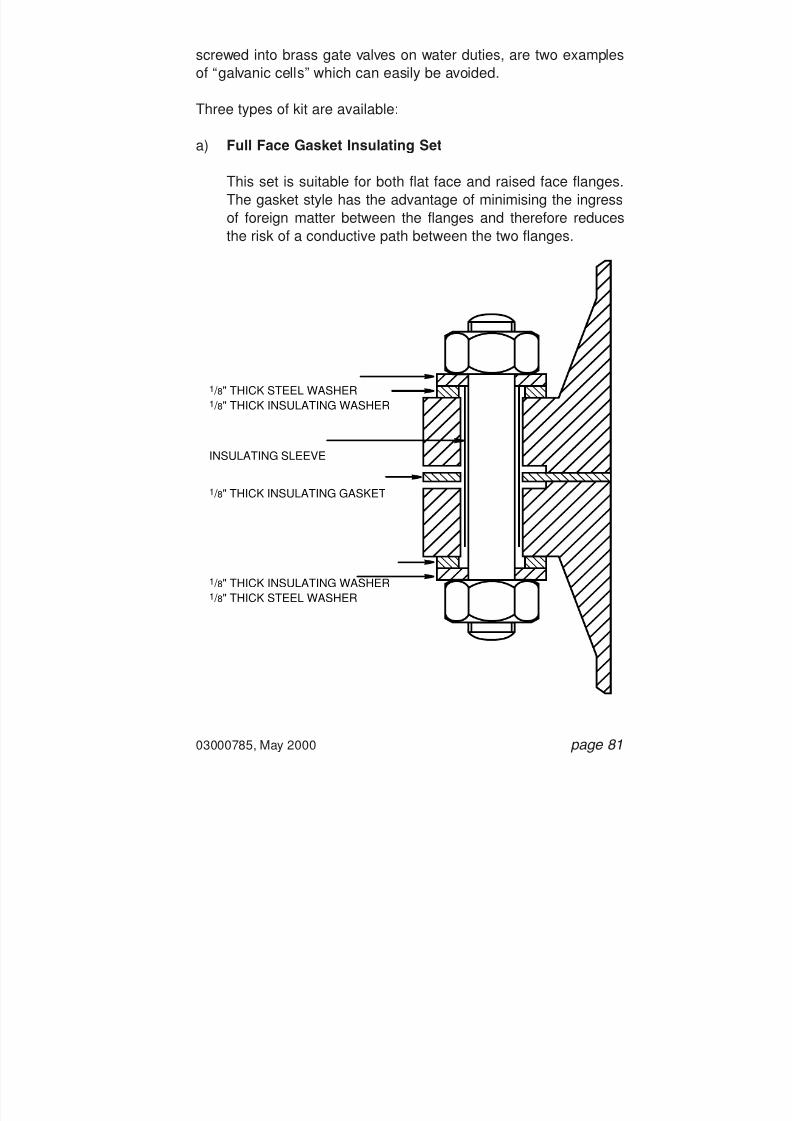
7/28/2019 117758036 Pipefitter Handbook
http://slidepdf.com/reader/full/117758036-pipefitter-handbook 83/161

7/28/2019 117758036 Pipefitter Handbook
http://slidepdf.com/reader/full/117758036-pipefitter-handbook 84/161

7/28/2019 117758036 Pipefitter Handbook
http://slidepdf.com/reader/full/117758036-pipefitter-handbook 85/161

7/28/2019 117758036 Pipefitter Handbook
http://slidepdf.com/reader/full/117758036-pipefitter-handbook 86/161
page 84 03000785, May 2000
5.14 Insulating Kit Identification andSpecification
a) Nominal Pipe Size and Pipe Schedule: Must always be
specified. Insulating gaskets, unlike CAF gaskets, are an exactfit, from the OD to the ID of the flange.
b) Flange Pressure Class: Always to be specified.
c) Style of Insulating Kit: Full face or inside bolt location. RTJgasket insulating sets are not used by BP Amoco.
d) Gasket Material: Usually phenolic laminate or neoprene facedphenolic laminate.
5.15 Insulating Kits - Do s and Don ts
Do s
a) Always use a new insulating kit which has not been removedfrom the manufacturer’s sealed package. Good insulationrequires the insulating parts of the kit to be clean and undam-aged.
b) Follow the manufacturer’s installation instructions.
c) Use a torque wrench or tensioning equipment to tension thestudbolts to the manufacturer’s recommendations. This isimportant as insulating gaskets are particularly susceptible tosplitting or crushing if overloaded.
d) Ensure that the flange face and the studbolts are clean.

7/28/2019 117758036 Pipefitter Handbook
http://slidepdf.com/reader/full/117758036-pipefitter-handbook 87/161
03000785, May 2000 page 85
e) Check for any conducting paths between the two matingflanges which would otherwise render the insulating gasketsineffective.
f) If in doubt, seek advice from your Engineering Department.
Don ts
a) Do not re-use old, damaged or unclean insulating kits. Thesewill not provide effective insulation and may be subject togasket failure.
b) Do not mix and match parts from different insulation kits.
c) Do not use air driven impact tools when bolting up a flange asthe may cause the insulating washers to crack.

7/28/2019 117758036 Pipefitter Handbook
http://slidepdf.com/reader/full/117758036-pipefitter-handbook 88/161

7/28/2019 117758036 Pipefitter Handbook
http://slidepdf.com/reader/full/117758036-pipefitter-handbook 89/161

7/28/2019 117758036 Pipefitter Handbook
http://slidepdf.com/reader/full/117758036-pipefitter-handbook 90/161
page 88 03000785, May 2000
I S O L A
T E D
I S O L A
T E D
N O T
I S O L A
T E D
N O T
I S O L A
T E D
IsolatedSpade
IsolatedSpectacle
Not IsolatedSpectacle
Not IsolatedSpacer with
Indicator Hole

7/28/2019 117758036 Pipefitter Handbook
http://slidepdf.com/reader/full/117758036-pipefitter-handbook 91/161
03000785, May 2000 page 89
7. Screwed Piping Joints
The use of screwed piping joints, especially on new installations orplants, is becoming increasingly uncommon. On older sites, anabundance of screwed joints may still be found on a variety of serv-ices.
7.1 Threaded Joints
A variety of threaded joints exists. Those used on pipeworkare always tapered and identified by a standard, either NPT(American National Taper Pipe Thread) or BSP (BritishStandard Pipe Taper Thread). The two threads are notinterchangeable . Both 1 / 2” and 3 / 4” NB BSP and API havethe same number of threads (TPI) but have differing threadangles.
Sealing on a threaded joint will only take place on 2 to 3
threads within the joint once fully tightened. A thread com-pound is used to lubricate the threaded joint when initiallymaking it up. As the joint is tightened, the compound isforced into the peaks and troughs of the thread, therebyblocking potential spiral leak paths. Sealing between the
TAPERED THREAD
METAL TO METAL SEALOF THESE SURFACES
PTFE TAPE or LIQUID JOINTINGCOMPOUND FILLS THESE GAPS

7/28/2019 117758036 Pipefitter Handbook
http://slidepdf.com/reader/full/117758036-pipefitter-handbook 92/161

7/28/2019 117758036 Pipefitter Handbook
http://slidepdf.com/reader/full/117758036-pipefitter-handbook 93/161
PTFE is not to be used on bull plugs on heat exchangers.Liquid thread compound only is to be used as there is no iso-lation between the thread and the process.
PTFE tape is supplied in several thicknesses ranging fromStandard (0.075 mm thick) to Heavy Duty (0.2 mm thick).Which to use depends on the pipe (or tubing) size and themaximum pressure. Heavy Duty tape is used on “mechanical”pipe joints. Standard tape is commonly used on low pressure(up to 10 bar) small bore (3 to 25 mm diameter) instrumenttubing.
d) Liquid Thread Compounds
A variety of liquid thread compounds is available that will lubri-cate and seal a threaded joint. There is no risk in the “over-application” of a liquid compound, as there is with PTFE tape.Excess liquid will simply exude from the joint.
The manufacturer’s recommendations on use must always befollowed. Some compounds have limitations on service duties.Others require a setting time before pressure can be applied tothe system. Lists of the variety of thread jointing compoundsand their limitations on use are given below.
Jointing compounds should not be applied to any threaded joints on stainless steel or other exotic materials until the
chemical compatibility has been checked.
03000785, May 2000 page 91

7/28/2019 117758036 Pipefitter Handbook
http://slidepdf.com/reader/full/117758036-pipefitter-handbook 94/161
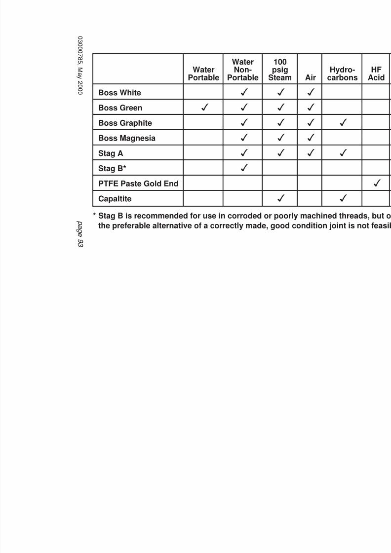
7/28/2019 117758036 Pipefitter Handbook
http://slidepdf.com/reader/full/117758036-pipefitter-handbook 95/161
0 3 0 0 0 7
8 5 ,M a y 2
0 0 0
p a g e 9 3
WaterPortable
Boss White
Boss Green
Boss Graphite
Boss Magnesia
Stag A
Stag B*
PTFE Paste Gold End
CapaltiteStag B is recommended for use in corroded or poorly machined threads, buthe preferable alternative of a correctly made, good condition joint is not fe
*
3
3
3
3
3
3
3
3
3
3
3
3
3
3
3
3
3
3
WaterNon-
Portable
100psig
SteamH
caAir

7/28/2019 117758036 Pipefitter Handbook
http://slidepdf.com/reader/full/117758036-pipefitter-handbook 96/161
page 94 03000785, May 2000
7.4 Screwed Unions
When pipe rotation is not permissible or practicable, say when joining a screwed pipe system, a screwed union is used. A threaded
ring nut connects the two halves of the union and the seal is madeby metal to metal contact of the profiled faces shown below. The twohalves of the union may either be screwed or socket welded to thepipe, as permitted by the pipe specification.
'A'
HEXAGON NUT, SCREWSONTO PART 'A' TO PULLUP AND MAKE THE SEAL
TWO HALVES OFUNION SCREWEDTO PIPE
MATING SURFACESFOR SEAL

7/28/2019 117758036 Pipefitter Handbook
http://slidepdf.com/reader/full/117758036-pipefitter-handbook 97/161

7/28/2019 117758036 Pipefitter Handbook
http://slidepdf.com/reader/full/117758036-pipefitter-handbook 98/161
page 96 03000785, May 2000
7.6 Screwed Joints - Do s and Don ts
Do s
a) Take care when unscrewing a joint, even though the systemmay have been depressurised:
- The seal on a union type joint breaks as soon as the ring nutis slackened.
- Threaded joints continue to seal until the threads finally
release, giving no warning of internal pressure. It is there-fore particularly important not to stand in front of plugsor caps when slackening them.
b) Prior to making a joint, check for thread damage, correct profileand correct engagement. Check with thread gauge if neces-sary.
c) Before applying any thread compound, a threaded joint shouldbe made up dry by hand. For pipe sizes up to 1 1 / 2 inch NB,ensure that at least 4 to 5 threads engage.
d) Check if there are any restrictions on the use of PTFE tape.There may be a total ban on PTFE tape, or it may be restrictedto low pressure non-hazardous duties or just to non-hydro-carbon duties.
- If using PTFE tape, ensure that you are using Heavy DutyPTFE tape (0.2 mm thick) on the mechanical (as opposed toinstrument) threaded joints. Wrap the tape in a clockwisedirection, no more than two layers thick and starting at theend of the pipe.
- If using a liquid thread compound, follow the manufac-turer’s recommendations. Some compounds have restricteduse and others require a setting time.

7/28/2019 117758036 Pipefitter Handbook
http://slidepdf.com/reader/full/117758036-pipefitter-handbook 99/161
03000785, May 2000 page 97
e) Thread tape should not be used on Bull Plugs , i.e. testingpoints onn exchanger nozzles.
f) When wrenching up screwed joints from hand-tight, for pipesizes up to 1 1 / 2 inch NB at least 3 more threads should beengaged (at least 7 to 8 threads engaged in total). For largerpipe sizes, thread engagement should be checked from ANSIBI.20.1 - Pipe Threads, General Purpose.
g) It may be necessary to use a thread locking compound on thelock nut of union type joints. This prevents them from looseningdue to vibrations.
Don ts
a) Do not cross threads, force screwed joints together or attemptto mate unmatched threads. A seal will not be made.
b) Do not make a seal by applying excessive PTFE tape tothreaded joints. If a seal cannot be made, the threads are prob-ably damaged and new threads should be cut on a freshsection of pipe.
c) PTFE tape should never extend beyond or overhang the firstthread on a joint as tape could shred and enter the fluid system.

7/28/2019 117758036 Pipefitter Handbook
http://slidepdf.com/reader/full/117758036-pipefitter-handbook 100/161
This page left intentionally blank.
page 98 03000785, May 2000
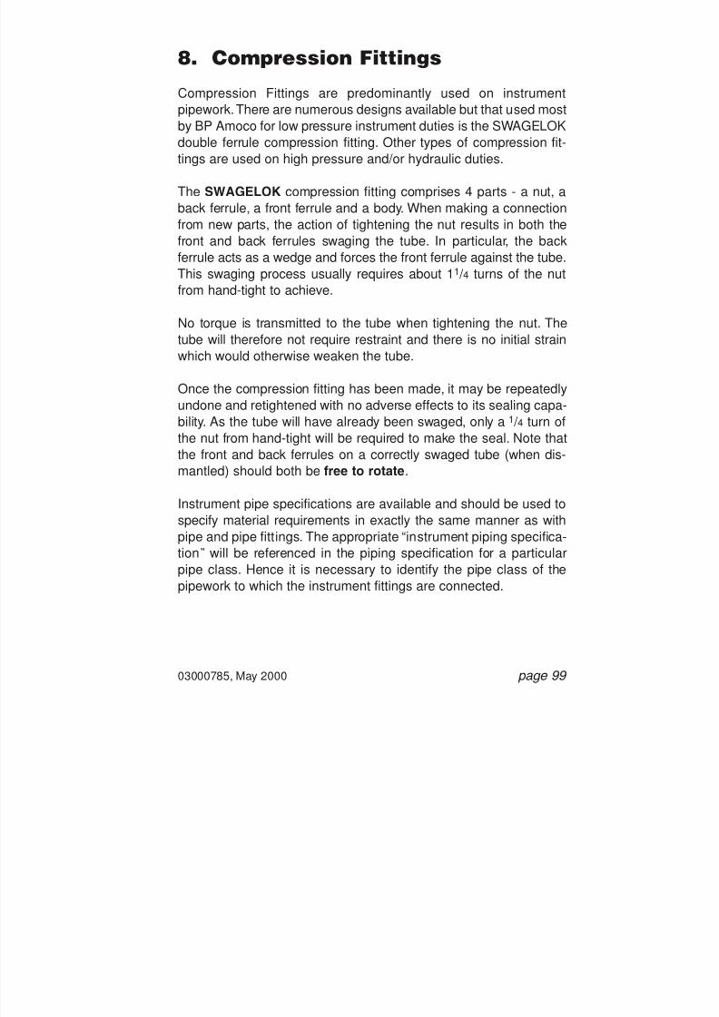
7/28/2019 117758036 Pipefitter Handbook
http://slidepdf.com/reader/full/117758036-pipefitter-handbook 101/161

7/28/2019 117758036 Pipefitter Handbook
http://slidepdf.com/reader/full/117758036-pipefitter-handbook 102/161
page 100 03000785, May 2000
Stainless Steel OD Pipe
NPT Thread
NUT
BACKFERRULE
FRONTFERRULE
BODY

7/28/2019 117758036 Pipefitter Handbook
http://slidepdf.com/reader/full/117758036-pipefitter-handbook 103/161
8.1 Compression Fitting Specification andIdentification
a) Fitting Manufacturer: State the manufacturer and the manu-
facturer’s reference code for the particular fitting that yourequire. Refer to the instrument piping specification.
b) Tube OD: CARE!! Metric and imperial compression fittings areincompatible. Refer to the instrument pipe specification tocheck which is used.
c) Tube Wall Thickness: Normally not required. If in doubt aboutwhat appears to be a very thick or thin wall, check with themanufacturer, as they normally set limitations on the tube wallthickness.
d) Pressure: Again, not normally required but quote if in doubt.Other types of compression fittings will be specified for highpressure applications.
e) Fitting Material: Must be quoted and will be as specified in theinstrument piping specification.
f) Fitting Body Connection: Dependent on the application. Avariety of body connections is available and must be quoted tocomplete the description of the compression fitting, e.g. maleNPT straight, elbow or tee connectors, female connectors forparallel pipe thread, unions, reducing unions, etc.
03000785, May 2000 page 101
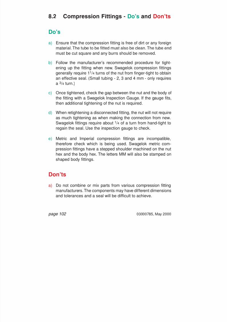
7/28/2019 117758036 Pipefitter Handbook
http://slidepdf.com/reader/full/117758036-pipefitter-handbook 104/161
page 102 03000785, May 2000
8.2 Compression Fittings - Do s and Don ts
Do s
a) Ensure that the compression fitting is free of dirt or any foreignmaterial. The tube to be fitted must also be clean. The tube endmust be cut square and any burrs should be removed.
b) Follow the manufacturer’s recommended procedure for tight-ening up the fitting when new. Swagelok compression fittingsgenerally require 1 1 / 4 turns of the nut from finger-tight to obtain
an effective seal. (Small tubing - 2, 3 and 4 mm - only requiresa 3 / 4 turn.)
c) Once tightened, check the gap between the nut and the body ofthe fitting with a Swagelok Inspection Gauge. If the gauge fits,then additional tightening of the nut is required.
d) When retightening a disconnected fitting, the nut will not require
as much tightening as when making the connection from new.Swagelok fittings require about 1 / 4 of a turn from hand-tight toregain the seal. Use the inspection gauge to check.
e) Metric and Imperial compression fittings are incompatible,therefore check which is being used. Swagelok metric com-pression fittings have a stepped shoulder machined on the nuthex and the body hex. The letters MM will also be stamped onshaped body fittings.
Don ts
a) Do not combine or mix parts from various compression fittingmanufacturers. The components may have different dimensions
and tolerances and a seal will be difficult to achieve.

7/28/2019 117758036 Pipefitter Handbook
http://slidepdf.com/reader/full/117758036-pipefitter-handbook 105/161
03000785, May 2000 page 103
b) Never turn the fitting body to make up the joint. The body shouldbe held and the nut rotated.
c) Do not use stainless steel tubing with brass fittings. The metaltubing material should either be the same or softer than thefitting material.
d) Do not use tubing which is scratched, depressed or deformed.Similarly, do not force oval tube into a fitting. The tube should becut back to sound material.
e) Do not use PTFE tape of any other thread sealing compound
between the nut and the body of the compression fitting.
f) Never bleed down a system by loosening the compressionfitting nut.

7/28/2019 117758036 Pipefitter Handbook
http://slidepdf.com/reader/full/117758036-pipefitter-handbook 106/161
page 104 03000785, May 2000
This page left intentionally blank.

7/28/2019 117758036 Pipefitter Handbook
http://slidepdf.com/reader/full/117758036-pipefitter-handbook 107/161
03000785, May 2000 page 105
9. Elastomeric O-Ring Seals
This section only applies to O-rings used on static seals such asbolted covers and joints. Dynamic seals, as found on pump shaftsfor example, are not covered.
The sealing arrangement on a static seal typically involves a groovecut into the face of the joint surface and into which the O-ring isplaced. The O-ring will stand slightly proud of the groove until axiallycompressed by the closure cover, thereby making the seal. Oncebolted up, application of pressure forces the O-ring across thegroove and increases its sealing effect. Hard back-up rings may beused to prevent the O-ring extruding into the clearance gap betweenthe joint surfaces.
P
P
BOLTED-UP
UNBOLTED
PRESSURE APPLIED
HARD BACK-UPRING INCLUDED

7/28/2019 117758036 Pipefitter Handbook
http://slidepdf.com/reader/full/117758036-pipefitter-handbook 108/161
page 106 03000785, May 2000
9.1 Selection of Elastomeric O-Rings
Selection of elastomeric O-rings ALWAYS needs carefulattention. Selection is normally made by the designer of the
joint who will consider both the service duty and the jointdesign as follows:
Service Duty:
a) Fluid, including any contaminants and/or additives.Certain elastomers may be susceptible to chemicalattack,for example by H 2S, methanol or glycol.
Always check chemical resistance of a variety ofelastomers and plastics (see Appendix 1, Section 4).
b) Temperature range. Elastomers have operating tem-perature ranges outside which their desirable proper-ties may degenerate. For example, chemical hardeningat high temperatures, brittleness at low temperatures.
c) Pressure range. Note that certain operating conditionscan produce a “full vacuum” and may require a special
joint design.
d) Any transient or cyclic conditions, including thenumber of cycles. For example, rapid decompression
or “blow-down” may have serious consequences oncertain gas permeable O-rings. Special grades of elas-tomer are available where explosive decompressionmight be a problem (see “Explosive DecompressionDamage”).
e) Required operating life. Note that ozone, UV light,radioactivity, heat and oxygen may result in prematureageing and gradual loss of properties even beforeinstallation.

7/28/2019 117758036 Pipefitter Handbook
http://slidepdf.com/reader/full/117758036-pipefitter-handbook 109/161
03000785, May 2000 page 107
Design of Joint:
a) Deformation of the O-ring. There is an optimum com-pression for O-rings used in static seals, above orbelow which permanent deformation and loss ofsealing capability may result.
b) Hardness of the O-ring. Hardness of elastomers ismeasured in units of Shore A or D or in InternationalRubber Hardness Degrees (IRHD). In general, harderO-rings are selected for higher pressures and/or toreduce extrusion; softer O-rings are selected for lower
pressures.
c) Clearance gap. The clearance gap of the jointdepends on machining tolerances, eccentricities andmetallic “breathing”. Poor machining may result inextrusion damage of the O-ring.
d) Use of back-up rings. Hard back-up rings may bespecified to reduce or eliminate O-ring extrusion, typi-cally for higher pressures and/or softer O-rings.
9.2 Elastomeric O-Ring Failures
The following examples of O-ring failure may be a result of incorrect
O-ring specification or poor joint design and manufacture. O-ringsremoved from joints should always be checked for evidence of suchfailure. Failed O-rings should be kept safe for further investigationby your Engineeirng Department and the O-ring manufacturer.
a) Extrusion Damage. Extrusion is characterised by “peeling” or“nibbling” of the O-ring surface. The O-ring extrudes too farinto the clearance gap and shears.

7/28/2019 117758036 Pipefitter Handbook
http://slidepdf.com/reader/full/117758036-pipefitter-handbook 110/161
page 108 03000785, May 2000
b) Compression Set Failure. The O-ring loses its elastomericmemory and flattens.
c) Explosive Decompression Damage. Under high pressure,gases may diffuse into the elastomer. On rapid decompression,the absorbed gases expand quickly and cause blistering andrupture of the O-ring.
9.3 Elastomeric O-Rings - Specificationand Identification
a) O-Ring Manufacturer, O-Ring Trade Name and Grade: Thisinformation should be specified on the schematic, arrangementdrawing or parts list associated with the equipment being main-tained.

7/28/2019 117758036 Pipefitter Handbook
http://slidepdf.com/reader/full/117758036-pipefitter-handbook 111/161
03000785, May 2000 page 109
b) O-Ring Type: Fully moulded O-rings should always be speci-fied.
c) O-Ring Dimensions: These will also be specified on the rele-vant schematic, arrangement drawing or parts list.
d) Back-Up Rings: Should only be used when indicated on therelevant schematic or drawing. Dimensions and material speci-fication will also be specified.
e) Service Duty: When appropriate, full service details should beprovided, e.g. for supply of new equipment.
In particular, service duty details should be provided when theoriginal O-ring specification is unknown or if considering use ofa different O-ring specification. The equipment manufacturermust be consulted and confirmation that the O-ring is suitablefor the service duty should be sought. Any proposed materialmust then be endorsed by your Engineering Department.
9.4 Installation of Elastomeric O-Rings -Do s and Don ts
Do s
a) Prior to installation, check for the correct material specification,trade name and manufacturer. Check that the O-ring (and back-up ring if specified) is the correct size, undamaged and clean.Template gauges are recommended for checking larger O-ringsizes.
b) Follow the manufacturer’s recommended installation instruc-tions. This applies to both the O-ring manufacturer and theequipment manufacturer.

7/28/2019 117758036 Pipefitter Handbook
http://slidepdf.com/reader/full/117758036-pipefitter-handbook 112/161
page 110 03000785, May 2000
c) Check the condition of the ring groove and any bearing sur-faces. Ensure that they are thoroughly cleaned with a recom-mended cleanser and dried before installation of the O-ring.CARE! Many cleaning of degreasing agents may chemi-cally attack the elastomer.
d) O-rings may be lubricated only where specified lubricants arerecommended by the supplier.
e) Always use fully moulded O-rings.
f) Take care not to cut, pinch or shear an O-ring when assembling
the joint.
Don ts
a) Never force or stretch the O-ring into a groove for which it is notspecifically designed.
b) Do not use unmarked O-rings or O-rings that have not beenstored in the supplier’s packing.
c) Do not install an O-ring with an expired shelf life.
d) Do not make up an O-ring joint if the previous O-ring showedevidence of faliure. Check with your Engineering Department
first.
e) Never cut O-rings to size and then glue or bond back together.
f) Do not estimate O-ring dimensions from the groove dimensions.Only use the schematic, arrangement drawing or parts list forthe equipment you are dealing with.
g) Do not re-use hard back-up rings. New back-up rings must befitted when installing new O-rings.

7/28/2019 117758036 Pipefitter Handbook
http://slidepdf.com/reader/full/117758036-pipefitter-handbook 113/161
03000785, May 2000 page 111
Appendix 1
Miscellaneous Technical Data
1. Bolts Material Specifications2. Hydraulic Bolt Tensioning3. Surface Finish Values for Tongue and Groove Small Male/
Female and Ring Joint Facings4. Chemical Resistance - Selected Elastomers and Plastics

7/28/2019 117758036 Pipefitter Handbook
http://slidepdf.com/reader/full/117758036-pipefitter-handbook 114/161
1. Bolts Material Specifications
page 112 03000785, May 2000
WorkingTemp ˚C Alloy Type
Min. Max.-20
-100
-20
-200
-200
-200
-200
-250
400
400
520
575
575
600
600
750
1% ChromiumMolybdenum
1% ChromiumMolybdenum
1% ChromiumMolybdenum - Vanadium
Austenitic ChromiumNickel 18/8
(Type 321 and 347)
Austenitic ChromiumNickel 18/8(Type 304)
Austenitic ChromiumNickel Molybdenum(Type 316)
Precipitation HardeningAustenitic NickelChromium
Precipitation HardeningNickel ChromiumTitanium AluminiumAlloy
Austenitic NickelChromiumMolybdenum Copper
Duplex Stainless SteelHigher Chromium
Duplex Stainless Steel
Nickel Copper Alloy
Nickel Copper AlloyPrecipitation Hardening
4882B7
4882L7
(Impact Tested)
4882B16
4882B8T, B8TX, B8C
and B8CX
4882B8
4882B8M
4882B17B
4882B08A
-
-
-
3076NA13
3076NA18
A193B7
A320L7
(Impact Tested)
A193B16
Aa193/A320B8T and B8C
A193/A320B8
A193/A320B8M
-
-
B473(UNS-N08020)
-(UNSS-S32550)
A276
(UNS-S31803)
B164(UNS-04400)
-(SAE AMS 4676)
AMBIENT
AMBIENT
AMBIENT
AMBIENT
AMBIENT
Material Specificationand Bolt Grade
Min. Max.4882
2H or 4
4882K4
48827
48828T and 8C
48828
48828M
488217B
80A
-
-
-
-
-
A1942H or 4
A1944
(Impact Tested)
A1947
A1948T and 8C
A1948
A1948M
-
-
-
-
-
-
-
Nut Grade
BS ASTM
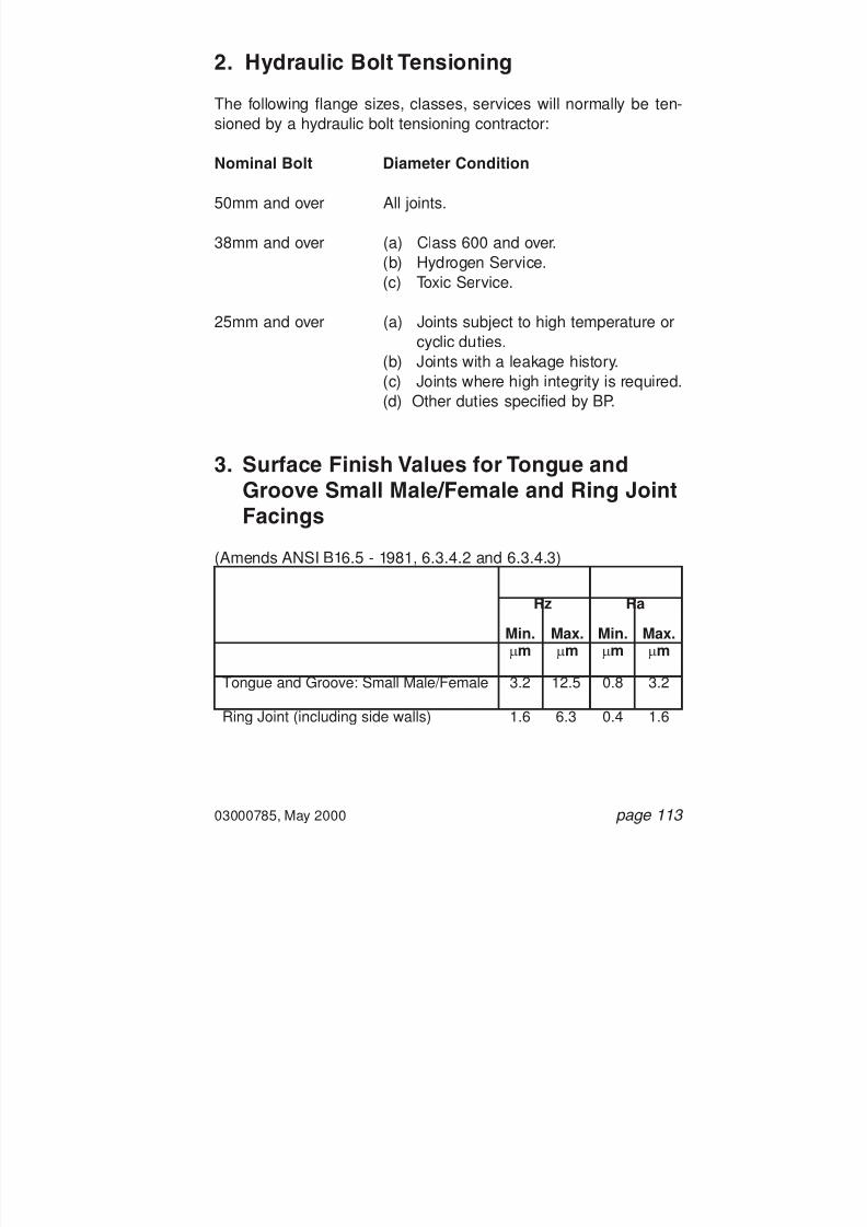
7/28/2019 117758036 Pipefitter Handbook
http://slidepdf.com/reader/full/117758036-pipefitter-handbook 115/161
03000785, May 2000 page 113
2. Hydraulic Bolt Tensioning
The following flange sizes, classes, services will normally be ten-sioned by a hydraulic bolt tensioning contractor:
Nominal Bolt Diameter Condition
50mm and over All joints.
38mm and over (a) Class 600 and over.(b) Hydrogen Service.(c) Toxic Service.
25mm and over (a) Joints subject to high temperature orcyclic duties.
(b) Joints with a leakage history.(c) Joints where high integrity is required.(d) Other duties specified by BP.
3. Surface Finish Values for Tongue andGroove Small Male/Female and Ring JointFacings
(Amends ANSI B16.5 - 1981, 6.3.4.2 and 6.3.4.3)
Tongue and Groove: Small Male/Female
Ring Joint (including side walls)
3.2
1.6
0.8
0.4
3.2
1.6
12.5
6.3
Min.mm
Max.mm
Min.mm
Max.mm
Rz Ra

7/28/2019 117758036 Pipefitter Handbook
http://slidepdf.com/reader/full/117758036-pipefitter-handbook 116/161
page 114 03000785, May 2000
4. Chemical Resistance -Selected Elastomers and Plastics
The following tables are only intended as guidance. Further spe-
cialised advice should be sought from your EngineeringDepartment when assessing material suitability for a particularapplication.
Key to Performance:
Code Rating Significance
1 Good Satisfactory performance in relativelyhigh level of chemical.
2 Fair Satisfactory only if low temperature and/ or low level of chemical.
3 Poor Performance depends on required lifeand level of chemical.
4 Bad No tolerance to chemical - DO NOT USE.
5 Unknown No data available.

7/28/2019 117758036 Pipefitter Handbook
http://slidepdf.com/reader/full/117758036-pipefitter-handbook 117/161
03000785, May 2000 page 115
MATERIAL CODECHEMICAL NATURE
TRADENAME
OIL Aliphatic HydrocarbonsAromatic HydrocarbonsCrude Oil (< 120 oC)Crude Oil (> 120 oC)
SOUR CRUDE OILSOUR NATURAL GAS
OIL BASED MUDWATER BASED MUDWATERSTEAMINHIBITORS AminesCOMPLETION FLUIDS CaCl/CaBr
ZnBr K2CO3
BRINE SeawaterCONTROL FLUIDS Mineral Oils
Glycol BasedALCOHOLS MethanolACIDS HCI (dilute)
HCI (concentrated)HF (< 65% cold)Acetic Acid (Hot)
SURFACTANTSCHLORINATED SOLVENTS
METHANECARBON DIOXIDEH2S (< 80 oC and < 100 ppm)H2S (> 150 oC and > 15%)
TEMPERATURE LIMITSNormal Low Temp Duty ( oC)Normal High Temp Duty ( oC)
CRPolychloropreneRubberNEOPRENE
232433
222331112211341424
2214
-45100
AE/AUPolyurethaneRubberADIPRENE
232433
211321124124245444
2134
-3090
NBRNitrileRubberBUNA-N
121422
112321421111343414
1124
-30120
ECO/COEpichloro-hydrinHYDRIN
111433
111221121111135254
1124
-40135
HNBRHydrogenatedNitrileTHERBAN
232322
211121311111243333
1114
-25150
EPDMEthylene-propylene-dieneNORDEL
444443
411121211311131314
4214
-40150
FKMVDF Fluoro-elastomerVITON
111222
112131111114111411
1223
-20200
FCMTFE/P Fluoro-elastomerAFLAS
122222
211111111211111313
1212
10230
FFKMPerfluoro-elastomerCHEMBRAZ/KALREZ
111122
111111111111111111
1111
0230
ELASTOMERIC SEALING MATERIALS
ETFEE/TFE Fluoro-PolymerTEFZEL
111111
111111111111111111
1111
-190200
PEEKPolyether-etherketoneVICTREX
111111
111111111111122211
1111
-190250
PTFEPolytetra-fluoroethyleneTEFLON
111111
111111111111111111
1111
-190290
ENGINEERING PLASTIC BACK-UP MATERIALS

7/28/2019 117758036 Pipefitter Handbook
http://slidepdf.com/reader/full/117758036-pipefitter-handbook 118/161
03000785, May 2000 page 117
Appendix 2
Dimensional Data
1. ANSI B16.5 Basic Flange Dimensions.
2. ANSI B16.5 Flange Bolt Hole and StudboltDimensions.
3. ANSI B16.5 Ring Joint Facing and RTJGasket Dimensions.
4. Spades for RF Flanges.
5. Spades for RTJ Flanges.
6. Pipe Schedules.
7. ANSI B16.9 and ANSI B16.28 Butt WeldingElbows and Return Bends.
8. ANSI B16.9 Butt Welding Reducers, Tees,
Lap Joint Stub Ends and Caps.9. Weight of Welded and Seamless Pipe.
10. Table of Gauges.
11. Decimal Equivalents of Fractions.

7/28/2019 117758036 Pipefitter Handbook
http://slidepdf.com/reader/full/117758036-pipefitter-handbook 119/161

7/28/2019 117758036 Pipefitter Handbook
http://slidepdf.com/reader/full/117758036-pipefitter-handbook 120/161
03000785, May 2000 page 119
1.1.1 Basic Flange Dimensions for ANSI B16.5 Class 150
P I P E F L A N G E
L E N G T H T H R O '
H U B D 1
N O T E S :
( 1 ) ( 2 )
( 3 ) S o c k e t w e l d
f l a n g e s o n l y s p e c i f i e d
f o r 1 / 2
t o 3 i n c h N
. B . D
i m e n s i o n
D 1 a s
f o r s l i p - o n
f l a n g e s .
A l l d i m e n s i o n s i n
i n c h e s .
R a i s e d
f a c e t h i c k n e s s f o r R F f l a n g e s = 0 . 0 6
i n c h . S e e
5 . 3 f o r R T J
f l a n g e s .
1 / 2
3 / 4
1
2
3
4
6
8
1 0
1 2
1 4
1 6
1 8 2 0
2 4
1 1 / 2
2 7 / 3
2
1 3 / 6
4
1 5 / 1
6
2 3 / 8
3 1 / 2
4 1 / 2
6 5 / 8
8 5 / 8
1 0 3 / 4 1 2 3 / 4
1 4
1 6
1 8 2 0
2 4
1 2 9 / 3
2
7 / 1
6
1 / 2
9 / 1
6
3 / 4
1 5 / 1
6
1 5 / 1
6
1
1 1 / 8
1 3 / 1
6
1 1 / 4
1 3 / 8
1 7 / 1
6
1 9 / 1
6
1 1 1 / 1
6
1 7 / 8
1 1 / 1
6
1 3 / 1
6
1 1 / 2
1 5 / 1
6
3 1 / 1
6
4 1 / 4
5 5 / 1
6
7 9 / 1
6
9 1 1 / 1
6
1 2 1 4 3 / 8
1 5 3 / 4
1 8
1 9 7 / 8
2 2
2 6 1 / 8
2 9 / 1
6
5 / 8
5 / 8
1 1 / 1
6
1
1 3 / 1
6
1 5 / 1
6
1 9 / 1
6
1 3 / 4
1 1 5 / 1
6
2 3 / 1
6
2 1 / 4
2 1 / 2
2 1 1 / 1
6
2 7 / 8
3 1 / 4
7 / 8
5 / 8
5 / 8
1 1 / 1
6
1
1 3 / 1
6
1 5 / 1
6
1 9 / 1
6
1 3 / 4
1 1 5 / 1
6
2 3 / 1
6
3 1 / 8
3 7 / 1
6
3 1 3 / 1
6
4 1
/ 1 6
4 3 / 8
7 / 8
1 7 / 8
2 1 / 1
6
2 3 / 1
6
2 1 / 2
2 3 / 4
3
3 1 / 2
4
4
4 1 / 2
5
5
5 1 / 2
5 1 1 / 1
6
6
2 7 / 1
6
3 1 / 2
3 7 / 8
4 1 / 4
6
7 1 / 2
9
1 1 1 3 1 / 2
1 6
1 9
2 1 2 3 1 / 2
2 5 2 7 1 / 2
3 2
5
N o m
i n a l P i p e
S i z e
O u t s i d e
D i a m e t e r
T h i c k n e s s
S l i p - O n
L a p p e d
W e l d
N e c k
O u t s i d e
D i a m e t e r
H u b
D i a m e t e r
A 1
B C
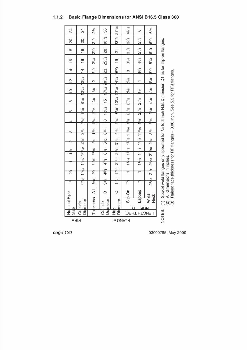
7/28/2019 117758036 Pipefitter Handbook
http://slidepdf.com/reader/full/117758036-pipefitter-handbook 121/161
page 120 03000785, May 2000
1.1.2 Basic Flange Dimensions for ANSI B16.5 Class 300
P I P E F L A N G E
L E N G T H T H R O '
H U B D 1
N O T E S :
( 1 ) ( 2 )
( 3 ) S o c k e t w e l d
f l a n g e s o n l y s p e c i f i e d
f o r 1 / 2
t o 3 i n c h N
. B . D
i m e n s i o n
D 1 a s
f o r s l i p - o n
f l a n g e s .
A l l d i m e n s i o n s i n
i n c h e s .
R a i s e d
f a c e t h i c k n e s s f o r R F f l a n g e s = 0 . 0 6
i n c h . S e e
5 . 3 f o r R T J
f l a n g e s .
1 / 2
3 / 4
1
2
3
4
6
8
1 0
1 2
1 4
1 6
1 8 2 0
2 4
1 1 / 2
2 7 / 3
2
1 3 / 6 4
1 5 / 1
6
2 3 / 8
3 1 / 2
4 1 / 2
6 5 / 8
8 5 / 8
1 0 3 / 4
1 2 3 / 4
1 4
1 6
1 8 2 0
2 4
1 2 9 / 3
2
9 / 1
6
5 / 8
1 1 / 1
6
7 / 8
1 1 / 8
1 1 / 4
1 7 / 1
6
1 5 / 8
1 7 / 8
2
2 1 / 8
2 1 / 4
2 3 / 8
2 1 / 2
2 3 / 4
1 3 / 1
6
1 1 / 2
1 7 / 8
2 1 / 8
3 5 / 1
6
4 5 / 8
5 3 / 4
8 1 / 8
1 0 1 / 4
1 2 5 / 8
1 4 3 / 4
1 6 3 / 4
1 9
2 1 2 3 1 / 8
2 7 5 / 8
2 3 / 4
7 / 8
1
1 1 / 1
6
1 5 / 1
6
1 1 1 / 1 6
1 7 / 8
2 1 / 1
6
2 7 / 1
6
2 5 / 8
2 7 / 8
3
3 1 / 4
3 1 / 2
3 3 / 4
4 3 / 1
6
1 3 / 1
6
7 / 8
1
1 1 / 1
6
1 5 / 1
6
1 1 1 / 1 6
1 7 / 8
2 1 / 1
6
2 7 / 1
6
3 3 / 4
4
4 3 / 8
4 3 / 4
5 1 / 8
5 1 / 2
6
1 3 / 1
6
2 1 / 1
6
2 1 / 4
2 7 / 1
6
2 3 / 4
3 1 / 8
3 3 / 8
3 7 / 8
4 3 / 8
4 5 / 8
5 1 / 8
5 5 / 8
5 3 / 4
6 1 / 4
6 3 / 8
6 5 / 8
2 1 1 / 1
6
3 3 / 4
4 5 / 8
4 7 / 8
6 1 / 2
8 1 / 4
1 0
1 2 1 / 2
1 5 1 7 1 / 2
2 0 1 / 2
2 3 2 5 1 / 2
2 8 3 0 1 / 2
3 6
6 1 / 8
N o m
i n a l P i p e
S i z e
O u t s i d e
D i a m e t e r
T h i c k n e s s
S l i p - O n
L a p p e d
W e l d
N e c k
O u t s i d e
D i a m e t e r
H u b
D i a m e t e r
A 1
B C

7/28/2019 117758036 Pipefitter Handbook
http://slidepdf.com/reader/full/117758036-pipefitter-handbook 122/161
03000785, May 2000 page 121
1.2 Basic Flange Dimensions for Classes 600 andAbove
C
A2SLIP-0N
WELDING
SOCKET
WELDING
LAPPED
WELDINGNECK
BLIND
B
D2
A2 D2
D2
A2
B
C
A2
B
C
D2A2
B
C
B

7/28/2019 117758036 Pipefitter Handbook
http://slidepdf.com/reader/full/117758036-pipefitter-handbook 123/161
page 122 03000785, May 2000
1.2.1 Basic Flange Dimensions for ANSI B16.5 Class 600
P I P E F L A N G E
L E N G T H T H R O '
H U B D 2
N O T E S :
( 1 ) ( 2 )
( 3 ) S o c k e t w e l d
f l a n g e s o n l y s p e c i f i e d
f o r 1 / 2
t o 3 i n c h N
. B . D
i m e n s i o n
D 2 a s
f o r s l i p - o n
f l a n g e s .
A l l d i m e n s i o n s i n
i n c h e s .
R a i s e d
f a c e t h i c k n e s s f o r R F f l a n g e s = 0 . 2 5
i n c h . S e e
5 . 3 f o r R T J
f l a n g e s .
1 / 2
3 / 4
1
2
3
4
6
8
1 0
1 2
1 4
1 6
1 8 2 0
2 4
1 1 / 2
2 7 / 3
2
1 3 / 6 4
1 5 / 1
6
2 3 / 8
3 1 / 2
4 1 / 2
6 5 / 8
8 5 / 8
1 0 3 / 4
1 2 3 / 4
1 4
1 6
1 8 2 0
2 4
1 2 9 / 3
2
9 / 1
6
5 / 8
1 1 / 1
6
1
1 1 / 4
1 1 / 2
1 7 / 8
2 3 / 1
6
2 1 / 2
2 5 / 8
2 3 / 4
3
3 1 / 4
3 1 / 2
4
7 / 8
1 1 / 2
1 7 / 8
2 1 / 8
3 5 / 1
6
4 5 / 8
6
8 3 / 4
1 0 3 / 4
1 3 1 / 2
1 5 3 / 4
1 7 1 9 1 / 2
2 1 1 / 2 2 4
2 8 1 / 4
2 3 / 4
7 / 8
1
1 1 / 1
6
1 7 / 1
6
1 1 3 / 1 6
2 1 / 8
2 5 / 8
3
3 3 / 8
3 5 / 8
3 1 1 / 1
6
4 3 / 1
6
4 5 / 8
5
5 1 / 2
1 1 / 4
7 / 8
1
1 1 / 1
6
1 7 / 1
6
1 1 3 / 1 6
2 1 / 8
2 5 / 8
3
4 3 / 8
4 5 / 8
5
5 1 / 2
6 6 1 / 2
7 1 / 4
1 1 / 4
2 1 / 1
6
2 1 / 4
2 7 / 1
6
2 7 / 8
3 1 / 4
4
4 5 / 8
5 1 / 4
6
6 1 / 8
6 1 / 2
7
7 1 / 4
7 1 / 2
8
2 3 / 4
3 3 / 4
4 5 / 8
4 7 / 8
6 1 / 2
8 1 / 4
1 0 3 / 4
1 4 1 6 1 / 2
2 0
2 2
2 3 3 / 4
2 7
2 9 1 / 4 3 2
3 7
6 1 / 8
N o m
i n a l P i p e
S i z e
O u t s i d e
D i a m e t e r
T h i c k n e s s
S l i p - O n
L a p p e d
W e l d
N e c k
O u t s i d e
D i a m e t e r
H u b
D i a m e t e r
A 2
B C

7/28/2019 117758036 Pipefitter Handbook
http://slidepdf.com/reader/full/117758036-pipefitter-handbook 124/161
03000785, May 2000 page 123
1.2.2 Basic Flange Dimensions for ANSI B16.5 Class 900
P I P E F L A N G E
L E N G T H T H R O '
H U B D 2
N O T E S :
( 1 ) ( 2 )
( 3 ) S o c k e t w e l d
f l a n g e s o n l y s p e c i f i e d
f o r 1 / 2
t o 3 i n c h N
. B . D
i m e n s i o n
D 2 a s
f o r C l a s s 1 5 0 0 s l i p - o n
f l a n g e s .
A l l d i m e n s i o n s i n
i n c h e s .
R a i s e d
f a c e t h i c k n e s s f o r R F f l a n g e s = 0 . 2 5
i n c h . S e e
5 . 3 f o r R T J
f l a n g e s .
1 / 2
3 / 4
1
2
3
4
6
8
1 0
1 2
1 4
1 6
1 8 2 0
2 4
1 1 / 2
2 7 / 3
2
1 3 / 6 4
1 5 / 1
6
2 3 / 8
3 1 / 2
4 1 / 2
6 5 / 8
8 5 / 8
1 0 3 / 4
1 2 3 / 4
1 4
1 6
1 8 2 0
2 4
1 2 9 / 3
2
1 1 / 2
1 3 / 4
2 3 / 1
6
2 1 / 2
2 3 / 4
3 1 / 8
3 3 / 8
3 1 / 2
4 4 1 / 4
5 1 / 2
5
6 1 / 4
9 1 / 4
1 1 3 / 4
1 4 1 / 2
1 6 1 / 2
1 7 3 / 4
2 0
2 2 1 / 4 2 4 1 / 2
2 9 1 / 2
2 1 / 8
2 3 / 4
3 3 / 8
4
4 1 / 4
4 5 / 8
5 1 / 8
5 1 / 4
6 6 1 / 4
8
2 1 / 8
2 3 / 4
3 3 / 8
4 1 / 2
5
5 5 / 8
6 1 / 8
6 1 / 2
7 1 / 2
8 1 / 4
1 0 1 / 2
4
4 1 / 2
5 1 / 2
6 3 / 8
7 1 / 4
7 7 / 8
8 3 / 8
8 1 / 2
9 9 3 / 4
1 1 1 / 2
9 1 / 2
1 1 1 / 2
1 5 1 8 1 / 2
2 1 1 / 2
2 4
2 5 1 / 4
2 7 3 / 4
3 1 3 3 3 / 4
4 1
N o m
i n a l P i p e
S i z e
O u t s i d e
D i a m e t e r
T h i c k n e s s
S l i p - O n
U S E
C L A S S 1 5 0 0
D I M E N S I O N S
I N
T H E S E S I Z E S
L a p p e d
W e l d
N e c k
O u t s i d e
D i a m e t e r
H u b
D i a m e t e r
A 2
B C

7/28/2019 117758036 Pipefitter Handbook
http://slidepdf.com/reader/full/117758036-pipefitter-handbook 125/161
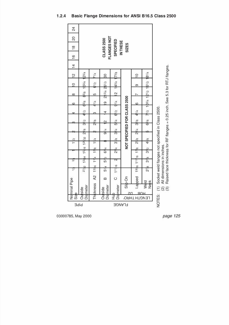
7/28/2019 117758036 Pipefitter Handbook
http://slidepdf.com/reader/full/117758036-pipefitter-handbook 126/161
03000785, May 2000 page 125
1.2.4 Basic Flange Dimensions for ANSI B16.5 Class 2500
P I P E F L A N G E
L E N G T H T H R O '
H U B D 2
N O T E S :
( 1 ) ( 2 )
( 3 ) S o c k e t w e l d
f l a n g e s n o t s p e c i f i e d
i n C l a s s
2 5 0 0 .
A l l d i m e n s i o n s i n
i n c h e s .
R a i s e d
f a c e t h i c k n e s s f o r R F f l a n g e s = 0 . 2 5
i n c h . S e e
5 . 3 f o r R T J f l a n g e s .
1 / 2
3 / 4
1
2
3
4
6
8
1 0
1 2
1 4
1 6
1 8 2 0
2 4
1 1 / 2
2 7 / 3
2
1 3 / 6
4
1 5 / 1
6
2 3 / 8
3 1 / 2
4 1 / 2
6 5 / 8
8 5 / 8
1 0 3 / 4 1 2 3 / 4
1 2 9 / 3
2
1 3 / 1
6
1 1 / 4
1 3 / 8
2
2 5 / 8
3
4 1 / 4
5
6 1 / 2
7 1 / 4
1 3 / 4
1 1 1 / 1
6
2
2 1 / 4
3 3 / 4
5 1 / 4
6 1 / 2
9 1 / 4
1 2 1 4 3 / 4 1 7 3 / 8
3 1 / 8
1 9 / 1
6
1 1 1 /
1 6
1 7 / 8
2 3 / 4
3 5 / 8
4 1 / 4
6
7
9
1 0
2 3 / 8
2 7 / 8
3 1 / 8
3 1 / 2
5
6 5 / 8
7 1 / 2
1 0 3 / 4
1 2 1 / 2
1 6 1 / 2 1 8 1 / 4
4 3 / 8
5 1 / 4
5 1 / 2
6 1 / 4
9 1 / 4
1 2
1 4
1 9 2 1 3 / 4
2 6 1 / 2
3 0
8
N o m
i n a l P i p e
S i z e
O u t s i d e
D i a m e t e r
T h i c k n e s s
S l i p - O n
L a p p e d
W e l d
N e c k
O u t s i d e
D i a m e t e r
H u b
D i a m e t e r
A 2
B C
N O T S P E C I F I E D F O R C L A S S 2 5 0 0
C L A S S 2 5 0 0
F L A N G E S N O
T
S P E C I F I E D
I N T H E S E
S I Z E S

7/28/2019 117758036 Pipefitter Handbook
http://slidepdf.com/reader/full/117758036-pipefitter-handbook 127/161
page 126 03000785, May 2000
2. ANSI B16.5 Flange Bolt Hole and Stud BoltDimensions
F
G
E
H
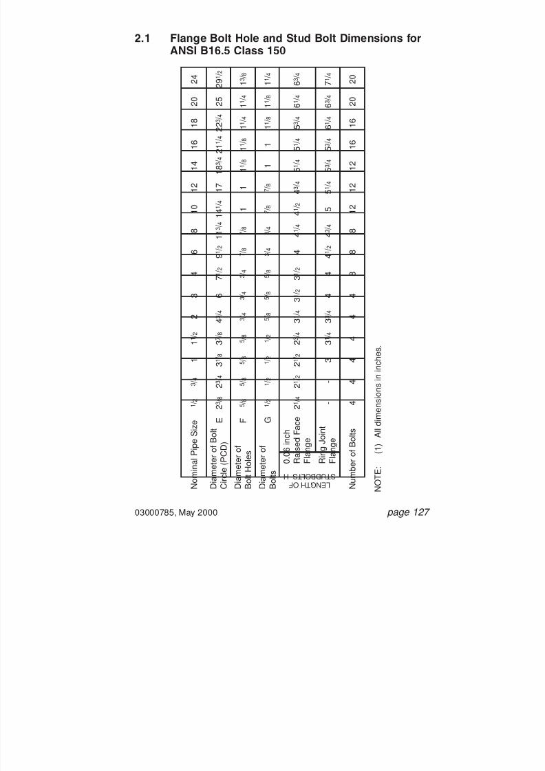
7/28/2019 117758036 Pipefitter Handbook
http://slidepdf.com/reader/full/117758036-pipefitter-handbook 128/161
03000785, May 2000 page 127
2.1 Flange Bolt Hole and Stud Bolt Dimensions forANSI B16.5 Class 150
L E N G T H O F S T U D B O L T S H
N O T E :
( 1 ) A l l d i m e n s i o n s i n
i n c h e s .
1 / 2
3 / 4
1
2
3
4
6
8
1 0
1 2
1 4
1 6
1 8
2 0
2 4
1 1 / 2
2 3 / 8
2 3 / 4
3 1 / 8
4 3 / 4
6
7 1 / 2
9 1 / 2
1 1 3 / 4
1 4 1 / 4
1 7
1 8 3 / 4
2 1 1 / 4
2 2 3 / 4
2 5
2 9 1 / 2
3 7 / 8
5 / 8
5 / 8
5 / 8
3 / 4
3 / 4
3 / 4
7 / 8
7 / 8
1
1
1 1 / 8
1 1 / 8
1 1 / 4
1 1 / 4
1 3 / 8
5 / 8
2 1 / 4
2 1 / 2
2 1 / 2
3 1 / 4
3 1 / 2
3 1 / 2
4
4 1 / 4
4 1 / 2
4 3
/ 4
5 1 / 4
5 1 / 4
5 3 / 4
6 1 / 4
6 3 / 4
2 3 / 4
-
-
3
3 3 / 4
4
4
4 1 / 2
4 3 / 4
5
5 1
/ 4
5 3 / 4
5 3 / 4
6 1 / 4
6 3 / 4
7 1 / 4
3 1 / 4
4
4
4
4
4
8
8
8
1 2
1 2
1 2
1 6
1 6
2 0
2 0
4
1 / 2
1 / 2
1 / 2
5 / 8
5 / 8
5 / 8
3 / 4
3 / 4
7 / 8
7 / 8
1
1
1 1 / 8
1 1 / 8
1 1 / 4
1 / 2
N o m i n a l P
i p e S i z e
D i a m e t e r o f B o l t
C i r c l e
( P C D )
0 . 0 6 i n c h
R a i s e d
F a c e
F l a n g e
R i n g J o i n t
F l a n g e
N u m b e r o f B o l t s
D i a m e t e r o f
B o l t s
D i a m e t e r o f
B o l t H o l e s
F G E
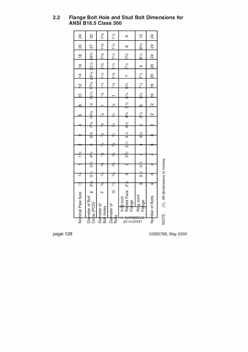
7/28/2019 117758036 Pipefitter Handbook
http://slidepdf.com/reader/full/117758036-pipefitter-handbook 129/161
page 128 03000785, May 2000
2.2 Flange Bolt Hole and Stud Bolt Dimensions forANSI B16.5 Class 300
L E N G T H O F S T U D B O L T S H
N O T E :
( 1 ) A l l d i m e n s i o n s i n
i n c h e s .
1 / 2
3 / 4
1
2
3
4
6
8
1 0
1 2
1 4
1 6
1 8
2 0
2 4
1 1 / 2
2 5 / 8
3 1 / 4
3 1 / 2
5
6 5 / 8
7 7 / 8
1 0 5 / 8
1 3 1 5 1 / 4
1 7 3 / 4
2 0 1 / 4
2 2 1 / 2
2 4 3 / 4
2 7
3 2
4 1 / 2
5 / 8
3 / 4
3 / 4
3 / 4
7 / 8
7 / 8
7 / 8
1
1 1 / 8
1 1 / 4
1 1 / 4
1 3 / 8
1 3 / 8
1 3 / 8
1 5 / 8
7 / 8
2 1 / 2
3
3
3 1 / 2
4 1 / 4
4 1 / 2
4 3 / 4
5 1 / 2
6 1 / 4
6 3 / 4
7
7 1 / 2
7 3 / 4
8
9
3 1 / 2
3
3 1 / 2
3 1 / 2
4
4 3 / 4
5
5 1 / 2
6
6 3 / 4
7 1 / 4
7 1 / 2
8
8 1 / 4
8 3 / 4
1 0
4
4
4
4
8
8
8
1 2
1 2
1 6
1 6
2 0
2 0
2 4
2 4
2 4
4
1 / 2
5 / 8
5 / 8
5 / 8
3 / 4
3 / 4
3 / 4
7 / 8
1
1 1 / 8
1 1 / 8
1 1 / 4
1 1 / 4
1 1 / 4
1 1 / 2
3 / 4
N o m i n a l P
i p e S i z e
D i a m e t e r o f B o l t
C i r c l e
( P C D )
0 . 0 6 i n c h
R a i s e d
F a c e
F l a n g e
R i n g J o i n t
F l a n g e
N u m b e r o f B o l t s
D i a m e t e r o f
B o l t s
D i a m e t e r o f
B o l t H o l e s
F G E

7/28/2019 117758036 Pipefitter Handbook
http://slidepdf.com/reader/full/117758036-pipefitter-handbook 130/161
03000785, May 2000 page 129
2.3 Flange Bolt Hole and Stud Bolt Dimensions forANSI B16.5 Class 600
L E N G T H O F S T U D B O L T S H
N O T E :
( 1 ) A l l d i m e n s i o n s i n
i n c h e s .
1 / 2
3 / 4
1
2
3
4
6
8
1 0
1 2
1 4
1 6
1 8
2 0
2 4
1 1 / 2
2 5 / 8
3 1 / 4
3 1 / 2
5
6 5 / 8
8 1 / 2
1 1 1 / 2
1 3 3 / 4
1 7
1 9 1 / 4
2 0 3 / 4
2 3 3 / 4
2 5 3 / 4
2 8 1 / 2
3 3
4 1 / 2
5 / 8
3 / 4
3 / 4
3 / 4
7 / 8
1
1 1 / 8
1 1 / 4
1 3 / 8
1 3 / 8
1 1 / 2
1 5 / 8
1 3 / 4
1 3 / 4
2
7 / 8
3
3 1 / 2
3 1 / 2
4 1 / 4
5
5 3 / 4
6 3 / 4
7 1 / 2
8 1 / 2
8 3 / 4
9 1 / 4
1 0
1 0 3 / 4
1 1 1 / 4
1 3
4 1 / 4
3
3 1 / 2
3 1 / 2
4 1 / 4
5
5 3 / 4
6 3 / 4
7 3 / 4
8 1 / 2
8 3 / 4
9 1 / 4
1 0
1 0 3 / 4
1 1 1 / 2
1 3 1 / 4
4 1 / 4
4
4
4
8
8
8
1 2
1 2
1 6
2 0
2 0
2 0
2 0
2 4
2 4
4
1 / 2
5 / 8
5 / 8
5 / 8
3 / 4
7 / 8
1
1 1 / 8
1 1 / 4
1 1 / 4
1 3 / 8
1 1 / 2
1 5 / 8
1 5 / 8
1 7 / 8
3 / 4
N o m i n a l P
i p e S i z e
D i a m e t e r o f B o l t
C i r c l e
( P C D )
0 . 2 5 i n c h
R a i s e d
F a c e
F l a n g e
R i n g J o i n t
F l a n g e
N u m b e r o f B o l t s
D i a m e t e r o f
B o l t s
D i a m e t e r o f
B o l t H o l e s
F G E

7/28/2019 117758036 Pipefitter Handbook
http://slidepdf.com/reader/full/117758036-pipefitter-handbook 131/161
page 130 03000785, May 2000
2.4 Flange Bolt Hole and Stud Bolt Dimensions forANSI B16.5 Class 900
L E N G T H O F S T U D B O L T S H
N O T E :
( 1 ) A l l d i m e n s i o n s i n
i n c h e s .
1 / 2
3 / 4
1
2
3
4
6
8
1 0
1 2
1 4
1 6
1 8
2 0
2 4
1 1 / 2
7 1 / 2
9 1 / 4
1 2 1 / 2
1 5 1 / 2
1 8 1 / 2
2 1
2 2 2 4 1 / 4
2 7 2 9 1 / 2
3 5 1 / 2
1
1 1 / 4
1 1 / 4
1 1 / 2
1 1 / 2
1 1 / 2
1 5 / 8
1 3 / 4
2
2 1 / 8
2 5 / 8
5 3 / 4
6 3 / 4
7 1 / 2
8 3 / 4
9 1 / 4
1 0
1 0 3 / 4
1 1 1 / 4
1 2 3 / 4
1 3 3 / 4
1 7 1 / 4
5 3 / 4
6 3 / 4
7 3 / 4
8 3 / 4
9 1 / 4
1 0
1 1 1 1 1 / 2
1 3 1 / 4
1 4 1 / 4
1 8
8
8
1 2
1 2
1 6
2 0
2 0
2 0
2 0
2 0
2 0
7 / 8
1 1 / 8
1 1 / 8
1 3 / 8
1 3 / 8
1 3 / 8
1 1 / 2
1 5 / 8
1 7 / 8
2
2 1 / 2
N o m i n a l P
i p e S i z e
D i a m e t e r o f B o l t
C i r c l e
( P C D )
0 . 2 5 i n c h
R a i s e d
F a c e
F l a n g e
R i n g J o i n t
F l a n g e
N u m b e r o f B o l t s
D i a m e t e r o f
B o l t s
D i a m e t e r o f
B o l t H o l e s
F G E
U S E
C L A S S 1 5 0 0
D I M
E N S I O N S
I N
T H E S E S I Z E S

7/28/2019 117758036 Pipefitter Handbook
http://slidepdf.com/reader/full/117758036-pipefitter-handbook 132/161
03000785, May 2000 page 131
2.5 Flange Bolt Hole and Stud Bolt Dimensions forANSI B16.5 Class 1500
L E N G T H O F S T U D B O L T S H
N O T E :
( 1 ) A l l d i m e n s i o n s i n
i n c h e s .
1 / 2
3 / 4
1
2
3
4
6
8
1 0
1 2
1 4
1 6
1 8
2 0
2 4
1 1 / 2
3 1 / 4
3 1 / 2
4
6 1 / 2
8
9 1 / 2
1 2 1 / 2
1 5 1 / 2
1 9
2 2 1 / 2
2 5 2 7 3 / 4
3 0 1 / 2
3 2 3 / 4
3 9
4 7 / 8
7 / 8
7 / 8
1
1
1 1 / 4
1 3 / 8
1 1 / 2
1 3 / 4
2
2 1 / 8
2 3 / 8
2 5 / 8
2 7 / 8
3 1 / 8
3 5 / 8
1 1 / 8
4 1 / 4
4 1 / 2
5
5 3 / 4
7
7 3 / 4
1 0 1 / 4
1 1 1 / 2
1 3 1 / 4
1 4 3 / 4
1 6 1 7 1 / 2
1 9 1 / 2
2 1 1 / 4
2 4 1 / 4
5 1 / 2
4 1 / 4
4 1 / 2
5
5 3 / 4
7
7 3 / 4
1 0 1 / 2
1 2 3 / 4
1 3 1 / 2
1 5 1 / 4
1 6 1 / 4
1 8 1 / 2
2 0 3 / 4
2 2 1 / 4
2 5 1 / 2
5 1 / 2
4
4
4
8
8
8
1 2
1 2
1 2
1 6
1 6
1 6
1 6
1 6
1 6
4
3 / 4
3 / 4
7 / 8
7 / 8
1 1 / 8
1 1 / 4
1 3 / 8
1 5 / 8
1 7 / 8
2
2 1 / 4
2 1 / 2
2 3 / 4
3
3 1 / 2
1
N o m i n a l P
i p e S i z e
D i a m e t e r o f B o l t
C i r c l e
( P C D )
0 . 2 5 i n c h
R a i s e d
F a c e
F l a n g e
R i n g J o i n t
F l a n g e
N u m b e r o f B o l t s
D i a m e t e r o f
B o l t s
D i a m e t e r o f
B o l t H o l e s
F G E

7/28/2019 117758036 Pipefitter Handbook
http://slidepdf.com/reader/full/117758036-pipefitter-handbook 133/161
page 132 03000785, May 2000
2.6 Flange Bolt Hole and Stud Bolt Dimensions forANSI B16.5 Class 2500
L E N G T H O F S T U D B O L T S H
N O T E :
( 1 ) A l l d i m e n s i o n s i n
i n c h e s .
1 / 2
3 / 4
1
2
3
4
6
8
1 0
1 2
1 4
1 6
1 8
2 0
2 4
1 1 / 2
3 1 / 2
3 3 / 4
4 1 / 4
6 3 / 4
9 1 0 3 / 4
1 4 1 / 2
1 7 1 / 4
2 1 1 / 4
2 4 3 / 8
5 3 / 4
7 / 8
7 / 8
1
1 1 / 8
1 3 / 8
1 5 / 8
2 1 / 8
2 1 / 8
2 5 / 8
2 7 / 8
1 1 / 4
4 3 / 4
5
5 1 / 2
7
8 3 / 4
1 0
1 3 1 / 2
1 5 1 9 1 / 4
2 1 1 / 4
6 3 / 4
4 3 / 4
5
5 1 / 2
7
9 1 0 1 / 4
1 4 1 5 1 / 2
2 0
2 2
6 3 / 4
4
4
4
8
8
8
8
1 2
1 2
1 2
4
3 / 4
3 / 4
7 / 8
1
1 1 / 4
1 1 / 2
2
2
2 1 / 2
2 3 / 4
1 1 / 8
N o m i n a l P
i p e S i z e
D i a m e t e r o f B o l t
C i r c l e
( P C D )
0 . 2 5 i n c h
R a i s e d
F a c e
F l a n g e
R i n g J o i n t
F l a n g e
N u m b e r o f B o l t s
D i a m e t e r o f
B o l t s
D i a m e t e r o f
B o l t H o l e s
F G E
C L A S S 2 5 0 0
F L A N G E S N O T
S P E C I F I E D
I N
T H E S E S I Z E S

7/28/2019 117758036 Pipefitter Handbook
http://slidepdf.com/reader/full/117758036-pipefitter-handbook 134/161
03000785, May 2000 page 133
3. Ring Joint Facing and RTJ GasketDimensions
P
K
K
O
L
2 3 o
J
J
I min
N
R TYPERING TYPE JOINT(OCTAGONAL)
M

7/28/2019 117758036 Pipefitter Handbook
http://slidepdf.com/reader/full/117758036-pipefitter-handbook 135/161
page 134 03000785, May 2000
3.1 Ring Joint Facing and RTJ Gasket Dimensionsfor ANSI B16.5 Class 150
O C T A G O N A L R I N G T Y P E J O I N T G A S K E T
F L A N G E G R O O V E N O T E :
( 1 ) ( 2 )
A l l d i m e n s i o n s
i n i n c h e s .
R i n g d i m e n s i o n s a s
p e r A N S I B 1 6 . 2 0 .
1 / 2
3 / 4
1
2
3
4
6
8
1 0
1 2
1 4
1 6
1 8
2 0
2 4
1 1 / 2
2 1 / 2
4
5 1 / 4
6 3 / 4
8 5 / 8
1 0 3 / 4
1 3
1 6
1 6 3 / 4
1 9
2 1 1 / 2
2 3 1 / 2
2 8
3 1 / 4
1 7 / 8
3 1 / 4
4 1 / 2
5 7 / 8
7 5 / 8
9 3 / 4
1 2
1 5
1 5 5 / 8
1 7 7 / 8
2 0 3 / 8
2 2
2 6 1 / 2
2 9 / 1
6
2 3 / 1
6
3 9 / 1
6
4 1 3 / 1
6
6 3 / 1
6
7 1 5 / 1
6
1 0 1 / 1
6
1 2 5 / 1
6
1 5 5 / 1
6 1 5 1 5 / 1
6
1 8 3 / 1
6
2 0 1 1 / 1
6
2 2 5 / 1
6
2 6 1 3 / 1
6
2 7 / 8
1 9 / 1
6
2 1 5 / 1
6
4 3 / 1
6
5 9 / 1
6
7 5 / 1
6
9 7 / 1
6
1 1 1 1 / 1
6
1 4 1 1 / 1
6 1 5 5 / 1
6
1 7 9 / 1
6
2 0 1 / 1
6
2 1 1 1 / 1
6
2 6 3 / 1
6
2 1 / 4
5 / 1
6
5 / 1
6
5 / 1
6
5 / 1
6
5 / 1
6
5 / 1
6
5 / 1
6
5 / 1
6
5 / 1
6
5 / 1
6
5 / 1
6
5 / 1
6
5 / 1
6
5 / 1
6
1
/ 4
1 / 4
1 / 4
1 / 4
1 / 4
1 / 4
1 / 4
1 / 4
1 / 4
1 / 4
1 / 4
1 / 4
1 / 4
1 / 4
1 1
/ 3 2
1 1 / 3
2
1 1 / 3
2
1 1 / 3
2
1 1 / 3
2
1 1 / 3
2
1 1 / 3
2
1 1 / 3
2
1 1 / 3
2
1 1 / 3
2
1 1 / 3
2
1 1 / 3
2
1 1 / 3
2
1 1 / 3
2
N o m i n a l P
i p e S i z e
D i a m e t e r
o f R a i s e d
S e c t i o n
O u t s i d e
D i a m e t e r
I n s i d e
D i a m e t e r
W i d t h
O
D e p t h o f
G r o o v e
G r o o v e
P i t c h
D i a m e t e r
J K
W i d t h
L M N I
1
/ 2
1 / 2
1 / 2
1 / 2
1 / 2
1 / 2
1 / 2
1 / 2
1 / 2
1 / 2
1 / 2
1 / 2
1 / 2
1 / 2
T h i c k n e s s P
1 5
2 2
2 9
3 6
4 3
4 8
5 2
5 6
5 9
6 4
6 8
7 2
7 6
1 9
R N u m
b e r
C L A S S 1 5 0 F L A N G E S N O T S P E C I F I E D I N T H E S E S I Z E S

7/28/2019 117758036 Pipefitter Handbook
http://slidepdf.com/reader/full/117758036-pipefitter-handbook 136/161

7/28/2019 117758036 Pipefitter Handbook
http://slidepdf.com/reader/full/117758036-pipefitter-handbook 137/161
page 136 03000785, May 2000
3.3 Ring Joint Facing and RTJ Gasket Dimensionsfor ANSI B16.5 Class 600
O C T A G O N A L R I N G T Y P E J O I N T G A S K E T
F L A N G E G R O O V E N O T E :
( 1 ) ( 2 )
A l l d i m e n s i o n s
i n i n c h e s .
R i n g d i m e n s i o n s a s p e r
A N S I B 1 6 . 2 0 .
1 / 2
3 / 4
1
2
3
4
6
8
1 0
1 2
1 4
1 6
1 8
2 0
2 4
1 1 / 2
2
2 1 / 4
2 3 / 4
4 1 / 4
5 3 / 4
6 7 / 8
9 1 / 2
1 1 7 / 8
1 4
1 6 1 / 4
1 8
2 0
2 2 5 / 8
2 5
2 9 1 / 2
3 9 / 1 6
1 1 1 / 3 2
1 1 1 / 1 6
2
3 1 / 4
4 7 / 8
5 7 / 8
8 5 / 1 6
1 0 5 / 8
1 2 3 / 4
1 5
1 6 1 / 2
1 8 1 / 2
2 1
2 3
2 7 1 / 4
2 1 1 / 1 6
1 1 9 / 3 2
2
2 5 / 1 6
3 1 1 / 1 6
5 5 / 1 6
6 5 / 1 6
8 3 / 4
1 1 1 / 1 6
1 3 3 / 1 6
1 5 7 / 1 6
1 6 1 5 / 1 6
1 8 1 5 / 1 6
2 1 7 / 1 6
2 3 1 / 2
2 7 7 / 8
3
1 3 / 3 2
1 3 / 8
1 1 1 / 1 6
2 1 3 / 1 6
4 7 / 1 6
5 7 / 1 6
7 7 / 8
1 0 3 / 1 6
1 2 5 / 1 6
1 4 9 / 1 6
1 6 1 / 1 6
1 8 1 / 1 6
2 0 9 / 1 6
2 2 1 / 2
2 6 5 / 8
2 3 / 8
1 / 4
5 / 1 6
5 / 1 6
7 / 1 6
7 / 1 6
7 / 1 6
7 / 1 6
7 / 1 6
7 / 1 6
7 / 1 6
7 / 1 6
7 / 1 6
7 / 1 6
1 / 2
5 / 8
5 / 1 6
7 / 3 2
1 / 4
1 / 4
5 / 1 6
5 / 1 6
5 / 1 6
5 / 1 6
5 / 1 6
5 / 1 6
5 / 1 6
5 / 1 6
5 / 1 6
5 / 1 6
3 / 8
7 / 1 6
1 / 4
9 / 3 2
1 1 / 3 2
1 1 / 3 2
1 5 / 3 2
1 5 / 3 2
1 5 /
3 2
1 5 / 3 2
1 5 / 3 2
1 5 / 3 2
1 5 / 3 2
1 5 / 3 2
1 5 / 3 2
1 5 / 3 2
1 7 / 3 2
2 1 / 3 2
1 1 / 3 2
N o m i n a l P
i p e S i z e
D i a m e t e r
o f R a i s e d
S e c t i o n
O u t s i d e
D i a m e t e r
I n s i d e
D i a m e t e r
W i d t h
O
D e p t h o f
G r o o v e
G r o o v e
P i t c h
D i a m e t e r
J K
W i d t h
L M N I
3 / 8
1 / 2
1 / 2
5 / 8
5 / 8
5 / 8
5 / 8
5 / 8
5 / 8
5 / 8
5 / 8
5 / 8
5 / 8
1 1 / 1 6
1 3 / 1 6
1 / 2
T h i c k n e s s P
1 1
1 3
1 6
2 3
3 1
3 7
4 5
4 9
5 3
5 7
6 1
6 5
6 9
7 3
7 7
2 0
R N u m
b e r
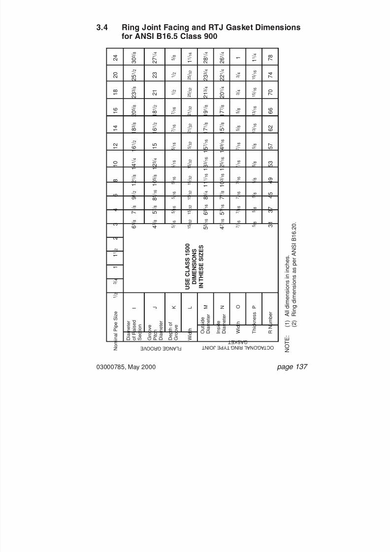
7/28/2019 117758036 Pipefitter Handbook
http://slidepdf.com/reader/full/117758036-pipefitter-handbook 138/161
03000785, May 2000 page 137
3.4 Ring Joint Facing and RTJ Gasket Dimensionsfor ANSI B16.5 Class 900
O C T A G O N A L R I N G T Y P E J O I N T G A S K E T
F L A N G E G R O O V E N O T E :
( 1 ) ( 2 )
A l l d i m e n s i o n s
i n i n c h e s .
R i n g d i m e n s i o n s a s
p e r A N S I B 1 6 . 2 0 .
1 / 2
3 / 4
1
2
3
4
6
8
1 0
1 2
1 4
1 6
1 8
2 0
2 4
1 1 / 2
6 1 / 8
7 1 / 8
9 1 / 2
1 2 1 / 8
1 4 1 / 4
1 6 1 / 2
1 8 3 / 8
2 0 5 / 8
2 3 3 / 8
2 5 1 / 2
3 0 3 / 8
4 7 / 8
5 7 / 8
8 5 / 1
6
1 0 5 / 8
1 2 3 / 4
1 5
1 6 1 / 2
1 8 1 / 2
2 1
2 3
2 7 1 / 4
5 5 / 1
6
6 5 / 1
6
8 3 / 4
1 1 1 / 1
6
1 3 3 / 1
6
1 5 7 / 1
6
1 7 1 / 8
1 9 1 / 8
2 1 3 / 4
2 3 3 / 4
2 8 1 / 4
4 7 / 1
6
5 7 / 1
6
7 7 / 8
1 0 3 / 1
6
1 2 5 / 1
6
1 4 9 / 1
6
1 5 7 / 8
1 7 7 / 8
2 0 1 / 4
2 2 1 / 4
2 6 1 / 4
7 / 1
6
7 / 1
6
7 / 1
6
7 / 1
6
7 / 1
6
7 / 1
6
5 / 8
5 / 8
3 / 4
3 / 4
1
5 / 1
6
5 / 1
6
5 / 1
6
5 / 1
6
5 / 1
6
5 / 1
6
7 / 1
6
7 / 1
6
1 / 2
1 / 2
5 / 8
1 5 / 3
2
1 5 / 3
2
1 5 / 3
2
1 5 / 3
2
1 5 / 3
2
1 5 / 3
2
2 1 / 3
2
2 1 / 3
2
2 5 / 3
2
2 5 / 3
2
1 1 / 1
6
N o m i n a l P
i p e S i z e
D i a m e t e r
o f R a i s e d
S e c t i o n
O u t s i d e
D i a m e t e r
I n s i d e
D i a m e t e r
W i d t h
O
D e p t h o f
G r o o v e
G r o o v e
P i t c h
D i a m e t e r
J K
W i d t h
L M N I
5 / 8
5 / 8
5 / 8
5 / 8
5 / 8
5 / 8
1 3 / 1
6
1 3 / 1
6
1 5 / 1
6
1 5 / 1
6
1 1 / 4
T h i c k n e s s P
3 1
3 7
4 5
4 9
5 3
5 7
6 2
6 6
7 0
7 4
7 8
R N u m
b e r
U S E C L A S S 1 5 0 0
D I M E N
S I O N S
I N T H E S
E S I Z E S
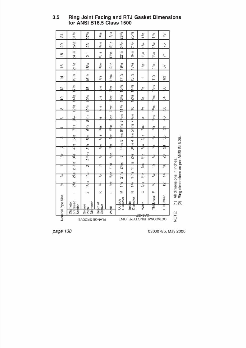
7/28/2019 117758036 Pipefitter Handbook
http://slidepdf.com/reader/full/117758036-pipefitter-handbook 139/161
page 138 03000785, May 2000
3.5 Ring Joint Facing and RTJ Gasket Dimensionsfor ANSI B16.5 Class 1500
O C T A G O N A L R I N G T Y P E J O I N T G A S K E T
F L A N G E G R O O V E N O T E :
( 1 ) ( 2 )
A l l d i m e n s i o n s
i n i n c h e s .
R i n g d i m e n s i o n s a s p e r
A N S I B 1 6 . 2 0 .
1 / 2
3 / 4
1
2
3
4
6
8
1 0
1 2
1 4
1 6
1 8
2 0
2 4
1 1 / 2
2 3 / 8
2 5 / 8
2 1 3 / 1 6
4 7 / 8
6 5 / 8
7 5 / 8
9 3 / 4
1 2 1 / 2
1 4 5 / 8
1 7 1 / 4
1 9 1 / 4
2 1 1 / 2
2 4 1 / 8
2 6 1 / 2
3 1 1 / 4
3 5 / 8
1 9 / 1 6
1 3 / 4
2
3 3 / 4
5 3 / 8
6 3 / 8
8 5 / 1 6
1 0 5 / 8
1 2 3 / 4
1 5
1 6 1 / 2
1 8 1 / 2
2 1
2 3
2 7 1 / 4
2 1 1 / 1 6
1 7 / 8
2 1 / 1 6
2 5 / 1 6
4 3 / 1 6
5 1 3 / 1 6
6 1 3 / 1 6
8 1 3 / 1 6
1 1 1 / 4
1 3 3 / 8
1 5 7 / 8
1 7 1 / 2
1 9 5 / 8
2 2 1 / 8
2 4 1 / 4
2 8 5 / 8
3
1 1 / 4
1 7 / 1 6
1 1 1 / 1 6
3 5 / 1 6
4 1 5 / 1 6
5 1 5 / 1 6
7 1 3 / 1 6
1 0
1 2 1 / 8
1 4 1 / 8
1 5 1 / 2
1 7 3 / 8
1 9 7 / 8
2 1 3 / 4
2 5 7 / 8
2 3 / 8
5 / 1 6
5 / 1 6
5 / 1 6
7 / 1 6
7 / 1 6
7 / 1 6
1 / 2
5 / 8
5 / 8
7 / 8
1
1 1 / 8
1 1 / 8
1 1 / 4
1 3 / 8
5 / 1 6
1 / 4
1 / 4
1 / 4
5 / 1 6
5 / 1 6
5 / 1 6
3 / 8
7 / 1 6
7 / 1 6
9 / 1 6
5 / 8
1 1 / 1 6
1 1 / 1 6
1 1 / 1 6
1 3 / 1 6
1 / 4
1 1 / 3 2
1 1 / 3 2
1 1 / 3 2
1 5 / 3 2
1 5 / 3 2
1 5 /
3 2
1 7 / 3 2
2 1 / 3 2
2 1 / 3 2
2 9 / 3 2
1 1 / 1 6
1 3 / 1 6
1 3 / 1 6
1 5 / 1 6
1 7 / 1 6
1 1 / 3 2
N o m i n a l P
i p e S i z e
D i a m e t e r
o f R a i s e d
S e c t i o n
O u t s i d e
D i a m e t e r
I n s i d e
D i a m e t e r
W i d t h
O
D e p t h o f
G r o o v e
G r o o v e
P i t c h
D i a m e t e r
J K
W i d t h
L M N I
1 / 2
1 / 2
1 / 2
5 / 8
5 / 8
5 / 8
1 1 / 1 6
1 3 / 1 6
1 3 / 1 6
1 1 / 1 6
1 1 / 4
1 3 / 8
1 3 / 8
1 1 / 2
1 5 / 8
1 / 2
T h i c k n e s s P
1 2
1 4
1 6
2 4
3 5
3 9
4 6
5 0
5 4
5 8
6 3
6 7
7 1
7 5
7 9
2 0
R N u m
b e r

7/28/2019 117758036 Pipefitter Handbook
http://slidepdf.com/reader/full/117758036-pipefitter-handbook 140/161
03000785, May 2000 page 139
3.6 Ring Joint Facing and RTJ Gasket Dimensionsfor ANSI B16.5 Class 2500
O C T A G O N A L R I N G T Y P E J O I N T G A S K E T
F L A N G E G R O O V E N O T E :
( 1 ) ( 2 )
A l l d i m e n s i o n s
i n i n c h e s .
R i n g d i m e n s i o n s a s p e r
A N S I B 1 6 . 2 0 .
1 / 2
3 / 4
1
2
3
4
6
8
1 0
1 2
1 4
1 6
1 8
2 0
2 4
1 1 / 2
2 9 / 1 6
2 7 / 8
3 1 / 4
5 1 / 4
6 5 / 8
8
1 1
1 3 3 / 8
1 6 3 / 4
1 9 1 / 2
4 1 / 2
1 1 1 / 1 6
2
2 3 / 8
4
5
6 3 / 1 6
9
1 1
1 3 1 / 2
1 6
3 1 / 4
2
2 5 / 1 6
2 1 1 / 1 6
4 7 / 1 6
5 1 / 2
6 1 3 / 1 6
9 3 / 4
1 1 7 / 8
1 4 5 / 8
1 7 1 / 4
3 1 1 / 1 6
1 3 / 8
1 1 1 / 1 6
2 1 / 1 6
3 9 / 1 6
4 1 / 2
5 9 / 1 6
8 1 / 4
1 0 1 / 8
1 2 3 / 8
1 4 3 / 4
2 1 3 / 1 6
5 / 1 6
5 / 1 6
5 / 1 6
7 / 1 6
1 / 2
5 / 8
3 / 4
7 / 8
1 1 / 8
1 1 / 4
7 / 1 6
1 / 4
1 / 4
1 / 4
5 / 1 6
3 / 8
7 / 1 6
1 / 2
9 / 1 6
1 1 / 1 6
1 1 / 1 6
5 / 1 6
1 1 / 3 2
1 1 / 3 2
1 1 / 3 2
1 5 / 3 2
1 7 / 3 2
2 1 /
3 2
2 5 / 3 2
2 9 / 3 2
1 3 / 1 6
1 5 / 1 6
1 5 / 3 2
N o m i n a l P
i p e S i z e
D i a m e t e r
o f R a i s e d
S e c t i o n
O u t s i d e
D i a m e t e r
I n s i d e
D i a m e t e r
W i d t h
O
D e p t h o f
G r o o v e
G r o o v e
P i t c h
D i a m e t e r
J K
W i d t h
L M N I
1 / 2
1 / 2
1 / 2
5 / 8
1 1 / 1 6
1 3 /
1 6
1 5 / 1 6
1 1 / 1 6
1 3 / 8
1 1 / 2
5 / 8
T h i c k n e s s P
1 3
1 6
1 8
2 6
3 2
3 8
4 7
5 1
5 5
6 0
2 3
R N u m
b e r
C L A S S 2 5 0 0
F L A N G E S N O T
S P E C I F I E D I N
T H E S E S I Z E S

7/28/2019 117758036 Pipefitter Handbook
http://slidepdf.com/reader/full/117758036-pipefitter-handbook 141/161
page 140 03000785, May 2000
4. Spades for Raised Face Flanges to SuitANSI B16.5
DC E
STANDARD TYPEREVERSIBLESPADE
THICKNESS = T
BORE AND RATINGSTAMPED ON THISFACE.
IDENTITY HOLE(APPLICABLE TO
RING SPADES ONLY)BORE AND RATINGSTAMPED ON THIS
FACE
C
B
A
B
D
C E
STANDARD TYPEBLIND SPADE
THICKNESS = T
G
F
B
L
D
C E
STANDARD TYPERING SPADE
G
F
B
A
L

7/28/2019 117758036 Pipefitter Handbook
http://slidepdf.com/reader/full/117758036-pipefitter-handbook 142/161
03000785, May 2000 page 141
A
SEE DETAILSOF LUGS
BORE AND RATINGSTAMPED ON LUG
12 D HOLE DRILLED IN RING SPADE LUGBLIND SPADE LUG TO BE UNDRILLED
DETAIL OF LUG FOR RING AND SPADES - 22KG AND UNDER
DETAIL OF LUG FOR RING AND BLIND SPADES - 22KG
LIFTING LUG ROD DIAMETERSUP TO WEIGHT OF 100KG: 016UP TO WEIGHT OF 100 - 300KG: 020UP TO WEIGHT OF 300 - 550KG: 025
OVER THE WEIGHT OF 550KG: 030
25
H
THICKNESS = T
ALTERNATIVE TYPEOF RING SPADE
B
ALTERNATIVE TYPEOF BLIND SPADE
B
BORE AND RATINGSTAMPED ON LUG
12 R CUTOUT IN RING SPADE LUGBLIND SPADE LUG TO BE UNCUT75
H

7/28/2019 117758036 Pipefitter Handbook
http://slidepdf.com/reader/full/117758036-pipefitter-handbook 143/161
page 142 03000785, May 2000
BORE AND RATINGSTAMPED ON THIS
FACETHICKNESS = T
A
B
ALTERNATIVE TYPEREVERSIBLE SPADE
B
2C
SEE DETAIL OFTIE BARS
TIE BAR 25x6 THICKFOR REVERSIBLE
SPADES WEIGHING 12KGAND UNDER
AND 40x10 THICK FORREVERSIBLE SPADES
WEIGHING 45KG AND UNDER
TIE BAR FOR REVERSIBLESPADES WEIGHING OVER 45KG
40J
40
K

7/28/2019 117758036 Pipefitter Handbook
http://slidepdf.com/reader/full/117758036-pipefitter-handbook 144/161
03000785, May 2000 page 143
4.1 Spades for Raised Face Flanges to SuitANSI B16.5 Class 150
N O T E :
( 1 ) D i m e n s i o n s
f r o m
B P S t a n d a r d D r a w
i n g S
- 0 7 5 5 M .
P i p e
S i z e
C L A S S 1 5 0
D I M E N S I O N S ( M M )
W E I G H T ( K G )
N P S
A
B
C
D
E
F
G
H
J
K
L
T
R i n g
B l i n d R e v
1 1 1 / 2 2 3 4 6 8 1 0 1 2 1 4 1 6 1 8 2 0 2 4
2 8 4 0 5 4 8 0 1 0 8
1 5 8 2 1 0
2 6 0 3 1 0
3 4 0 3 9 0
4 4 0 5 0 0
6 0 0
6 4 8 2 1 0 2
1 3 5 1 7 2
2 2 0 2 7 5
3 3 5 4 0 5
4 4 5 5 1 0
5 4 5 6 0 5
7 1 5
4 0 4 9 6 0 7 6 9 5 1 2 1
1 4 9 1 8 1
2 1 6 2 3 8
2 7 0 2 8 9
3 1 8 3 7 5
1 6
1 6
2 0
2 0
2 0
2 2
2 2
2 5
2 5
3 0
3 0
3 2
3 2
3 5
3 8 3 8 4 5 5 0 5 0 7 5 7 5 1 0 0
1 0 0 1 0 0
1 0 0 1 0 0
1 0 0 1 0 0
2 0 2 0 2 2 2 2 2 2 2 5 2 5 3 2 3 2 3 8 3 8 4 5 4 5 5 0
9 5 1 0 0
1 3 0 1 6 0
1 8 0 2 2 0
2 5 0 3 0 0
3 5 0 3 8 0
4 2 0 4 5 0
5 0 0 5 6 0
1 5 0 1 5 0
1 5 0 1 5 8
1 5 8 1 5 8
1 6 5 1 6 5
1 6 5 1 7 2
1 7 2 1 7 2
1 7 8 1 7 8
- - - - - - - - - - 4 0 4 0 4 0 4 5
- - - - - - - - - - 1 2 1 6 1 6 2 0
1 0 0 1 0 0 1 0 0 1 0 0 1 0 0 1 5 0 1 5 0 2 0 0 2 0 0 2 0 0 2 0 0 2 0 0 2 0 0 2 0 0
6 . 5
6 . 5
6 . 5
6 . 5
9 . 5
1 3 1 3 1 6 1 9 2 2 2 2 2 5 2 8 3 5
0 . 2 5
0 . 3 2
0 . 4 4
0 . 6 8
1 . 4
2 . 6
3 . 4
6 . 4
1 0 . 4
1 4 . 5
1 7 . 7
1 9 . 9
2 6 . 3
3 9 . 5
0 . 2 8
0 . 3 9
0 . 5 5
0 . 9 5
2 . 0 8
4 . 6 2
6 . 8
1 4 . 3
2 2 3 1 3 9 5 1 7 0 1 1 8
0 . 3
0 . 5
0 . 7 3
1 . 1 4
2 . 8
5 . 5
8 . 6
1 7 . 2
2 7 . 7
3 9 . 5
4 6 . 3
6 3 . 5
8 6 1 4 4

7/28/2019 117758036 Pipefitter Handbook
http://slidepdf.com/reader/full/117758036-pipefitter-handbook 145/161
4.2 Spades for Raised Face Flanges to SuitANSI B16.5 Class 300
page 144 03000785, May 2000
N O T E :
( 1 ) D i m e n s i o n s
f r o m
B P S t a n d a r d D r a w
i n g S - 0 7 5 5 M .
P i p e
S i z e
C L A S S 3 0 0
D I M E N S I O N S ( M M )
W E I G H T ( K G )
N P S
A
B
C
D
E
F
G
H
J
K
L
T
R i n g
B l i n d R e v
1 1 1 / 2 2 3 4 6 8 1 0 1 2 1 4 1 6 1 8 2 0 2 4
2 8 4 0 5 4 8 0 1 0 8
1 5 8 2 1 0
2 6 0 3 1 0
3 4 0 3 9 0
4 4 0 5 0 0
6 0 0
7 0 9 2 1 0 8
1 4 5 1 7 8
2 4 8 3 0 4
3 6 0 4 2 0
4 8 0 5 3 5
5 9 5 6 5 0
7 7 0
4 4 5 7 6 4 8 4 1 0 0
1 3 5 1 6 5
1 9 4 2 2 5
2 5 7 2 8 6
3 1 4 3 4 3
4 0 5
2 0
2 2
2 0
2 2
2 2
2 2
2 5
3 0
3 2
3 2
3 5
3 5
3 5
4 2
5 0 5 0 5 0 5 0 5 0 7 5 7 5 1 0 0
1 0 0 1 0 0
1 0 0 1 0 0
1 0 0 1 0 0
2 0 2 2 2 2 2 5 2 5 2 5 2 5 3 2 3 2 3 8 3 8 4 5 4 5 5 0
1 0 0 1 3 0
1 3 0 1 5 0
1 8 0 2 2 0
2 5 0 3 0 0
3 6 0 3 8 0
4 4 0 4 8 0
5 4 0 6 0 0
1 5 8 1 5 8
1 5 8 1 5 8
1 6 5 1 6 5
1 6 5 1 7 2
1 7 8 1 7 8
1 8 5 1 9 0
1 9 0 2 0 5
- - - - - - - - - 4 0 4 5 4 5 4 5 5 0
- - - - - - - - - 2 0 2 0 2 2 2 5 2 8
1 0 0
1 0 0
1 0 0
1 0 0
1 0 0
1 5 0
1 5 0
2 0 0
2 0 0
2 0 0
2 0 0
2 0 0
2 0 0
2 0 0
6 . 5
6 . 5
9 . 5
9 . 5
1 3 1 6 2 2 2 5 2 8 3 2 3 8 4 2 4 4 5 4
0 . 3
0 . 5
0 . 8 6
1 . 2 7
2 . 0 9
4 . 6 3
8 . 1 6
1 2 . 7
1 7 . 7
2 6 . 8
3 7 . 6
4 8 . 5
5 8 9 1
0 . 3 3
0 . 5 8
1 . 0 4
1 . 6 3
3 . 0
7 . 0
1 4 . 3
2 3 3 5 5 0 7 3 9 9 1 2 7
2 0 1
0 . 3 6
0 . 6 4
1 . 2 5
2 . 1 5
4 . 0
1 0 2 0 3 0 4 5 6 8 1 0 0
1 3 0 1 6 7
2 8 0

7/28/2019 117758036 Pipefitter Handbook
http://slidepdf.com/reader/full/117758036-pipefitter-handbook 146/161
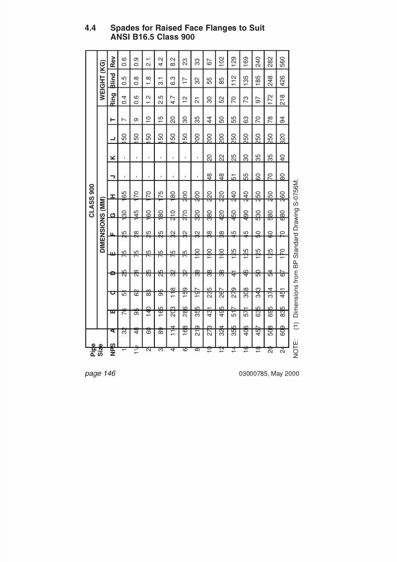
7/28/2019 117758036 Pipefitter Handbook
http://slidepdf.com/reader/full/117758036-pipefitter-handbook 147/161
4.4 Spades for Raised Face Flanges to SuitANSI B16.5 Class 900
page 146 03000785, May 2000
N O T E :
( 1 ) D i m e n s i o n s
f r o m
B P S t a n d a r d D r a w
i n g S
- 0 7 5 6 M .
P i p e
S i z e
C L A S S 9 0 0
D I M E N S I O N S ( M M )
W E I G H T ( K G )
N P S
A
B
C
D
E
F
G
H
J
K
L
T
R i n g
B l i n d R e v
1 1 1 / 2 2 3 4 6 8 1 0 1 2 1 4 1 6 1 8 2 0 2 4
3 2 4 8 6 0 8 9 1 1 4
1 6 8 2 1 9
2 7 3 3 2 4
3 5 5 4 0 6
4 5 7 5 0 8
6 0 9
7 6 9 5 1 4 0
1 6 5 2 0 3
2 8 6 3 5 5
4 3 1 4 9 5
5 1 7 5 7 1
6 3 5 6 9 5
8 3 5
5 1 6 2 8 3 9 5 1 1 8
1 5 9 1 9 7
2 3 5 2 6 7
2 7 9 3 0 8
3 4 3 3 7 4
4 5 1
2 5
2 8
2 5
2 5
3 2
3 2
3 8
3 8
3 8
4 1
4 5
5 0
5 4
6 7
7 5 7 5 7 5 7 5 7 5 7 5 1 0 0
1 0 0 1 0 0
1 2 5 1 2 5
1 2 5 1 2 5
1 7 0
2 5 2 8 2 5 2 5 3 2 3 2 3 2 3 8 3 8 4 5 4 5 5 0 6 0 7 0
1 3 0 1 4 5
1 6 0 1 8 0
2 1 0 2 7 0
3 2 0 3 8 0
4 2 0 4 5 0
4 9 0 5 3 0
5 8 0 6 8 0
1 6 5 1 7 0
1 7 0 1 7 5
1 8 0 2 0 0
2 0 0 2 2 0
2 2 0 2 4 0
2 4 0 2 5 0
2 5 0 2 6 0
- - - - - - - 4 8 4 8 5 1 5 5 6 0 7 0 8 0
- - - - - - - 2 0 2 2 2 5 3 0 3 5 3 5 4 0
1 5 0
1 5 0
1 5 0
1 5 0
1 5 0
1 5 0
2 0 0
2 0 0
2 0 0
2 5 0
2 5 0
2 5 0
2 5 0
3 2 0
7 9 1 0 1 5 2 0 3 0 3 5 4 4 5 0 5 5 6 3 7 0 7 8 9 4
0 . 4
0 . 6
1 . 2
2 . 5
4 . 7
1 2 2 1 3 0 5 2 7 0 7 3 9 7 1 7 2
2 1 8
0 . 5
0 . 8
1 . 8
3 . 1
6 . 3
1 7 3 2 5 5 8 5 1 1 2
1 3 5 1 8 5
2 4 8 4 2 6
0 . 6
0 . 9
2 . 1
4 . 2
8 . 2
2 3 3 3 6 7 1 0 2
1 2 9 1 6 9
2 4 0 2 8 2
5 6 0

7/28/2019 117758036 Pipefitter Handbook
http://slidepdf.com/reader/full/117758036-pipefitter-handbook 148/161
5. Spades for Ring Type Joint Flanges to SuitANSI B16.5
03000785, May 2000 page 147
TIE BAR 25x6 THICKFOR REVERSIBLE
SPADES WEIGHING 12KGAND UNDER
AND TIE BAR 40x10 THICKFOR REVERSIBLE SPADES
WEIGHING 45KG AND UNDER
TIE BAR FOR REVERSIBLESPADES WEIGHING OVER 45KG
40H
F
E
D
G
SEETIE BAR
DETAIL FORWEIGHTS
45KG ANDUNDER
SEETIE BARDETAIL FORWEIGHTS
OVER 45KG
RINGGROOVE
RINGGROOVE
RING GROOVE RING GROOVEDETAIL X
BORE AND RATINGSTAMPED ONBOTH FACES
DETAIL X
REVERSIBLE SPADE
E92 min
23 o
40
JTHICKNESS OFTHE BARS
A
D
J
AB
C
D

7/28/2019 117758036 Pipefitter Handbook
http://slidepdf.com/reader/full/117758036-pipefitter-handbook 149/161
page 148 03000785, May 2000
SEE LUG DETAILS
RING GROOVE RING GROOVE
BORE AND RATINGSTAMPED ON LUG
12 D HOLE DRILLED IN RING SPADE LUGBLIND SPADE LUG TO BE UNDRILLED
DETAIL OF LUG FOR RING AND SPADES - 22KG AND UNDER
DETAIL OF LUG FOR RING AND BLIND SPADES - 22KG
LIFTING LUG ROD DIAMETERSUP TO WEIGHT OF 100KG: 016UP TO WEIGHT OF 100 - 300KG: 020UP TO WEIGHT OF 300 - 550KG: 025OVER THE WEIGHT OF 550KG: 030
25
K
BLIND RING
BORE AND RATINGSTAMPED ON LUG
25 R CUTOUT IN RING SPADE LUGBLIND SPADE LUG TO BE UNCUT75
K
DETAIL X
B
C
DA

7/28/2019 117758036 Pipefitter Handbook
http://slidepdf.com/reader/full/117758036-pipefitter-handbook 150/161
5.1 Spades for Ring Type Joint Flanges to SuitANSI B16.5 Class 300
03000785, May 2000 page 149
N
O T E :
( 1 ) D i m e n s i o n s
f r o m B P S t a n d a r d D r a w
i n g S - 1 2 4 3 M .
P i p e
S i z e
C L A S S 3 0 0
D I M E N S I O N S ( M M )
W E I G H T ( K G )
N P S
A
B
C
D
E
F
G
H
J
K
R i n g
B l i n d R e v
1 1 1 / 2 2 3 4 6 8 1 0 1 2 1 4 1 6 1 8 2 0 2 4
7 0 9 0 1 1 0
1 4 5 1 7 5
2 4 0 3 0 0
3 5 5 4 1 5
4 5 5 5 1 0
5 7 5 6 3 5
7 5 0
2 5 4 0 5 5 8 0 1 0 5
1 5 5 2 0 5
2 6 0 3 1 0
3 3 5 3 8 5
4 4 0 4 9 0
5 9 0
2 2 2 2 2 5 2 5 2 6 3 4 3 6 4 0 4 5 4 8 5 2 5 8 6 4 7 6
5 0 . 8
6 8 . 3
8 2 . 6
1 2 3 . 8
1 4 9 . 2
2 1 1 . 1
2 6 9 . 9
3 2 3 . 8
3 8 1 . 0
4 1 9 . 1
4 6 9 . 9
5 3 3 . 4
5 8 4 . 2
6 9 2 . 2
6 . 4
6 . 4
7 . 9
7 . 9
7 . 9
7 . 9
7 . 9
7 . 9
7 . 9
7 . 9
7 . 9
7 . 9
9 . 5
1 1 . 1
8 . 7
8 . 7
1 1 . 9
1 1 . 9
1 1 . 9
1 1 . 9
1 1 . 9
1 1 . 9
1 1 . 9
1 1 . 9
1 1 . 9
1 1 . 9
1 3 . 5
1 6 . 7
1 1 5 1 4 0
1 5 0 1 9 0
2 3 0 2 9 0
3 5 5 4 2 0
4 8 0 5 3 5
6 0 0 6 6 0
7 2 5 8 5 0
- - - - - - - 3 0 4 0 4 0 4 0 4 0 4 0 4 5
6 6 6 1 0 1 0 1 0 1 5 1 5 1 5 2 0 2 0 2 5 2 5 3 0
1 5 8
1 5 8
1 5 8
1 5 8
1 6 5
1 6 5
1 6 5
1 7 2
1 7 8
1 7 8
1 8 5
1 9 0
1 9 0
2 0 5
0 . 6
0 . 9
1 . 4
2 . 4
3 . 3
7 . 1
1 0 . 7
1 6 . 4
2 1 . 7
2 8 . 2
3 4 . 2
4 8 . 8
6 4 . 8
1 0 1
0 . 7
1 . 1
2 . 0
3 . 3 5 1 2 2 0 3 2 4 8
6 1 . 5
8 3 1 7 7
1 5 8 2 6 4
1 . 2 2 3 .
5 5 . 5 8 1 9
3 0 . 5
4 8 . 5
7 0 9 0 1 2 0
1 6 6 2 2 5
3 6 9

7/28/2019 117758036 Pipefitter Handbook
http://slidepdf.com/reader/full/117758036-pipefitter-handbook 151/161
5.2 Spades for Ring Type Joint Flanges to SuitANSI B16.5 Class 600
page 150 03000785, May 2000
N
O T E :
( 1 ) D i m e n s i o n s
f r o m B P S t a n d a r d D r a w
i n g S - 1 2 4 3 M .
P i p e
S i z e
C L A S S 6 0 0
D I M E N S I O N S ( M M )
W E I G H T ( K G )
N P S
A
B
C
D
E
F
G
H
J
K
R i n g
B l i n d R e v
1 1 1 / 2 2 3 4 6 8 1 0 1 2 1 4 1 6 1 8 2 0 2 4
7 0 9 0 1 1 0
1 4 5 1 7 5
2 4 0 3 0 0
3 5 5 4 1 5
4 5 5 5 1 0
5 7 5 6 3 5
7 5 0
2 5 4 0 5 5 8 0 1 0 5
1 5 5 2 0 5
2 6 0 3 1 0
3 3 5 3 8 5
4 4 0 4 9 0
5 9 0
2 2 2 5 2 7 3 2 3 4 4 4 5 0 5 6 6 2 6 6 7 3 8 0 8 9 1 0 4
5 0 . 8
6 8 . 3
8 2 . 6
1 2 3 . 8
1 4 9 . 2
2 1 1 . 1
2 6 9 . 9
3 2 3 . 8
3 8 1 . 0
4 1 9 . 1
4 6 9 . 9
5 3 3 . 4
5 8 4 . 2
6 9 2 . 2
6 . 4
6 . 4
7 . 9
7 . 9
7 . 9
7 . 9
7 . 9
7 . 9
7 . 9
7 . 9
7 . 9
7 . 9
9 . 5
1 1 . 1
8 . 7
8 . 7
1 1 . 9
1 1 . 9
1 1 . 9
1 1 . 9
1 1 . 9
1 1 . 9
1 1 . 9
1 1 . 9
1 1 . 9
1 1 . 9
1 3 . 5
1 6 . 7
1 1 5 1 4 0
1 5 0 1 9 0
2 4 5 3 2 0
3 7 0 4 4 5
4 9 5 5 4 5
6 1 0 6 7 5
7 3 5 8 6 5
- - - - - - - 4 0 4 0 4 5 4 5 5 0 5 0 5 5
6 6 6 1 0 1 0 1 0 1 5 1 5 2 0 2 0 2 0 2 5 2 5 4 0
1 5 8
1 5 8
1 5 8
1 5 8
1 7 2
1 7 8
1 7 8
1 8 5
1 8 5
1 8 5
2 0 0
2 0 5
2 0 5
2 2 0
0 . 6
1 . 1
1 . 4
2 . 5
4 . 1 5
9 . 1
1 4 . 9
1 7 . 4
2 8 . 4
4 6 . 2
4 8 6 7 8 8 . 5
1 5 0
0 . 7
1 . 3 2 4 .
6 6 . 4
1 5 . 4
2 8 . 6
4 2 . 6
6 4 8 5 . 2
1 1 5 1 6 1
2 2 0 3 6 0
1 . 2
2 . 3
3 . 5 7
1 0 . 5
2 4 . 5
4 0 . 5
6 0 . 5
9 3 1 3 2
1 6 5 2 2 8
3 1 0 5 1 2

7/28/2019 117758036 Pipefitter Handbook
http://slidepdf.com/reader/full/117758036-pipefitter-handbook 152/161
5.3 Spades for Ring Type Joint Flanges to SuitANSI B16.5 Class 900
03000785, May 2000 page 151
N
O T E :
( 1 ) D i m e n s i o n s
f r o m B P S t a n d a r d D r a w
i n g S - 1 2 4 3 M .
P i p e
S i z e
C L A S S 9 0 0
D I M E N S I O N S ( M M )
W E I G H T ( K G )
N P S
A
B
C
D
E
F
G
H
J
K
R i n g
B l i n d R e v
1 1 1 / 2 2 3 4 6 8 1 0 1 2 1 4 1 6 1 8 2 0 2 4
7 0 9 0 1 2 5
1 5 5 1 8 0
2 4 0 3 1 0
3 5 0 4 2 0
4 6 5 5 2 5
5 9 5 6 5 0
7 7 0
2 5 4 0 5 0 7 5 1 0 0
1 5 0 1 9 5
2 4 5 2 9 0
3 2 0 3 6 5
4 1 5 4 5 5
5 6 0
2 2 2 5 3 2 3 8 4 1 5 0 6 0 6 6 7 6 8 9 9 5 1 0 8 1 1 4 1 3 2
5 0 . 8
6 8 . 2
9 5 . 2
1 2 3 . 8
1 4 9 . 2
2 1 1 . 1
2 6 9 . 9
3 2 3 . 8
3 8 1 . 0
4 1 9 . 2
4 6 9 . 8
5 3 3 . 4
5 8 4 . 2
6 9 2 . 2
6 . 4
6 . 4
7 . 9
7 . 9
7 . 9
7 . 9
7 . 9
7 . 9
7 . 9
1 1 . 1
1 1 . 1
1 2 . 7
1 2 . 7
1 5 . 9
8 . 7
8 . 7
1 1 . 9
1 1 . 9
1 1 . 9
1 1 . 9
1 1 . 9
1 1 . 9
1 1 . 9
1 6 . 7
1 6 . 7
1 9 . 8
1 9 . 8
2 7
1 2 5 1 5 0
1 9 0 2 1 5
2 5 5 3 3 0
4 0 5 4 7 0
5 3 5 5 7 0
6 3 5 7 1 0
7 6 0 9 1 5
- - - - - - 4 5 4 5 4 5 4 5 5 0 5 5 5 5 5 5
6 6 6 1 0 1 0 1 0 1 5 2 0 2 0 2 5 2 5 2 5 4 0 4 0
1 5 8
1 5 8
1 5 8
1 5 8
1 7 2
1 8 5
1 8 5
2 0 0
2 0 5
2 0 5
2 0 5
2 1 5
2 1 5
2 4 0
0 . 6
1 . 0 7
2 . 5
4 . 3
7 . 9
1 2 . 8
2 3 . 2
2 9 . 5
4 2 . 4
5 8 . 8
7 6 . 5
1 2 4 1 4 7
2 4 5
0 . 7
1 . 3 8
2 . 8 8
5 . 5 5
8 . 2 5
1 8 . 3
3 5 . 4
4 9 . 5
8 3 1 1 8
1 6 0 2 3 8
3 0 0 5 1 4
1 . 2
2 . 5
5 . 4
9 . 9
1 6 . 2
3 0 6 0 8 4 . 5
1 2 6 1 8 0
2 3 8 3 6 4
4 4 8 7 6 0

7/28/2019 117758036 Pipefitter Handbook
http://slidepdf.com/reader/full/117758036-pipefitter-handbook 153/161
5.4 Spades for Ring Type Joint Flanges to SuitANSI B16.5 Class 1500
page 152 03000785, May 2000
N
O T E :
( 1 ) D i m e n s i o n s
f r o m B P S t a n d a r d D r a w
i n g S - 1 2 4 3 M .
P i p e
S i z e
C L A S S 1 5 0 0
D I M E N S I O N S ( M M )
W E I G H T ( K G )
N P S
A
B
C
D
E
F
G
H
J
K
R i n g
B l i n d R e v
1 1 1 / 2 2 3 4 6 8 1 0 1 2 1 4 1 6 1 8 2 0 2 4
7 0 9 0 1 2 5
1 7 0 1 9 5
2 5 0 3 1 5
3 7 0 4 4 0
4 9 0 5 4 5
6 1 0 6 7 5
7 9 5
2 5 4 0 5 0 7 5 1 0 0
1 5 0 1 9 5
2 4 5 2 9 0
3 1 0 3 6 0
4 1 0 4 6 5
5 6 5
2 4 2 7 3 5 4 3 4 8 6 0 7 5 8 4 1 0 1 1 1 1 1 2 4 1 3 6 1 4 5 1 7 3
5 0 . 8
6 8 . 2
9 5 . 2
1 3 6 . 5
1 6 1 . 9
2 1 1 . 1
2 6 9 . 9
3 2 3 . 8
3 8 1 . 0
4 1 9 . 1
4 6 9 . 9
5 3 3 . 4
5 8 4 . 2
6 9 2 . 2
6 . 4
6 . 4
7 . 9
7 . 9
7 . 9
9 . 5
1 1 . 1
1 1 . 1
1 4 . 3
1 5 . 9
1 7 . 5
1 7 . 5
1 7 . 5
2 0 . 6
8 . 7
8 . 7
1 1 . 9
1 1 . 9
1 1 . 9
1 3 . 5
1 6 . 7
1 6 . 7
2 3 2 7 3 0 . 2
3 0 . 2
3 3 . 3
3 6 . 5
1 2 5 1 5 0
1 9 0 2 3 0
2 6 5 3 4 5
4 2 0 5 1 0
5 9 5 6 6 0
7 3 5 7 8 5
8 6 5 1 0 1 5
- - - - - - 5 0 5 5 5 5 6 5 7 0 7 5 8 5 9 5
6 6 6 1 0 1 0 1 0 2 0 2 0 2 5 2 5 3 0 3 0 4 0 4 0
1 5 8
1 5 8
1 5 8
1 5 8
1 7 2
1 7 8
1 9 0
2 0 5
2 0 5
2 3 0
2 3 0
2 5 0
2 6 0
2 8 5
0 . 6 4
1 . 1
2 . 7 4
5 . 8 6
8 . 2 4
1 4 . 6
2 8 . 3 5
4 0 6 5 . 7
9 6 . 4
1 2 6 . 8
1 7 1 . 5
2 1 3 . 1
3 2 9 . 3
0 . 7 4
1 . 4
3 . 3
7 . 3 8
1 0 . 8 6
2 2 . 9
4 6 . 1
6 9 . 6
1 1 8 . 8
1 6 2 . 5
2 2 6 . 2
3 1 3 . 9
4 0 5 . 5
6 6 7 . 6
1 . 3
2 . 6
5 . 1
1 3 . 4
1 9 . 3
3 7 . 7
7 5 1 1 1
1 8 7 2 6 1
3 5 6 4 8 9
5 2 3 1 0 0 2

7/28/2019 117758036 Pipefitter Handbook
http://slidepdf.com/reader/full/117758036-pipefitter-handbook 154/161
5.5 Spades for Ring Type Joint Flanges to SuitANSI B16.5 Class 2500
03000785, May 2000 page 153
N
O T E :
( 1 ) D i m e n s i o n s
f r o m B P S t a n d a r d D r a w
i n g S - 1 2 4 3 M .
P i p e
S i z e
C L A S S 2 5 0 0
D I M E N S I O N S ( M M )
W E I G H T ( K G )
N P S
A
B
C
D
E
F
G
H
J
K
R i n g
B l i n d
R e v
1 1 1 / 2 2 3 4 6 8 1 0 1 2
8 5 1 1 5
1 3 5 1 7 0
2 0 5 2 8 0
3 4 0 4 2 5
4 9 5
2 5 3 5 4 5 7 0 9 0 1 3 5
1 6 0 2 1 0
2 6 0
2 9 3 7 4 1 5 1 6 2 8 1 9 7 1 1 8 1 3 3
6 0 . 4
8 2 . 5
1 0 1 . 5
1 2 7 . 0
1 5 7 . 2
2 2 8 . 6
2 7 9 . 4
3 4 2 . 9
4 0 6 . 4
6 . 4
7 . 9
7 . 9
9 . 5
1 1 . 1
1 2 . 7
1 4 . 3
1 7 . 5
1 7 . 5
8 . 7
1 1 . 9
1 1 . 9
1 3 . 4
1 6 . 6
1 9 . 8
2 3 . 0
3 0 . 1
3 3 . 3
1 4 0 1 8 0
2 0 5 2 5 5
3 0 5 3 9 5
4 5 5 5 6 0
6 5 0
- - - - - 6 0 6 0 7 0 7 5
6 6 6 1 0 1 0 1 5 2 0 2 5 3 0
1 5 8
1 5 8
1 5 8
1 5 8
1 7 2
1 7 8
1 7 8
1 8 5
1 8 5
1 . 1
2 . 6 5
4 7 . 3
1 2 . 5 4
3 0 5 3 . 5
9 8 . 6
1 4 5
1 . 2
2 . 9
4 . 5
8 . 8 2
1 5 . 7
3 8 . 7
6 8 . 5
1 3 0 . 2
2 0 0 . 3
2 . 3
5 . 6
8 . 5
1 6 . 3
2 8 . 6
6 9 1 2 3
2 3 0 3 4 8

7/28/2019 117758036 Pipefitter Handbook
http://slidepdf.com/reader/full/117758036-pipefitter-handbook 155/161
6. Normal Wall Thickness for Pipe ScheduleSizes
page 154 03000785, May 2000
N o m i n a l
P i p e S i z e
O u t s i d e
D i a m e t e r
S C H
5
S C H
1 0
S C H
2 0
S C H
3 0
S C H
4 0
S C H
S C H
6 0
S C H
8 0
S C H
X S
S C H
1 0 0
S C H
1 2 0
S C H
1 4 0
S C H
1 6 0
S
C H
X X S
3 . 1 7 m m
1 / 8 " 1 0 . 3 m m
. 4 0 5 "
1 . 7 3
. 0 6 8
1 . 7 3
. 0 6 8
2 . 4 1
. 0 9 5
2 . 4 1
. 0 9 5
6 . 3 5 m m
1 / 4 " 1 3 . 7 m m
. 5 4 0 " 1 . 2 0
. 0 4 9 1 . 7 2
. 0 6 5
2 . 2 4
. 0 8 8
2 . 2 4
. 0 8 8
3 . 0 2
. 1 1 9
3 . 0 2
. 1 1 9
9 . 5 2 m m
3 / 8 " 2 1 . 3 m m
. 8 4 0 " 1 . 2 0
. 0 4 9 1 . 7 2
. 0 6 5
2 . 3 1
. 0 9 1
2 . 3 1
. 0 9 1
3 . 2 0
. 1 2 6
3 . 2 0
. 1 2 6
1 2 . 7 m m
1 / 2 " 1 0 . 3 m m
. 4 0 5 " 1 . 7 2
. 0 6 5 2 . 1 1
. 0 8 3
2 . 7 7
. 1 0 9
2 . 7 7
. 1 0 9
3 . 7 3
. 1 4 7
3 . 7 3
. 1 4 7
4 . 7 8
. 1 8 7
7 . 4 7
. 2 9 4
1 9 . 1 m m
3 / 4 " 2 6 . 7 m m
1 . 0 5 0 "
1 . 7 2
. 0 6 5 2 . 1 1
. 0 8 3
2 . 8 7
. 1 1 3
2 . 8 7
. 1 1 3
3 . 9 1
. 1 5 4
3 . 9 1
. 1 5 4
5 . 5 4
. 2 1 8
7 . 8 2
. 3 0 8
2 5 . 4 m m 1 "
3 3 . 4 m m
1 . 3 1 5 "
1 . 7 2
. 0 6 5 2 . 7 7
. 1 0 9
3 . 3 8
. 1 3 3
3 . 3 8
. 1 3 3
4 . 5 5
. 1 7 9
4 . 5 5
. 1 7 9
6 . 3 5
. 2 5 0
9 . 0 9
. 3 5 8
3 1 . 8 m m
1 1 / 4 "
4 2 . 2 m m
1 . 6 6 0 "
1 . 7 2
. 0 6 5 2 . 7 7
. 1 0 9
3 . 5 6
. 1 4 0
3 . 5 6
. 1 4 0
4 . 8 5
. 1 9 1
4 . 8 5
. 1 9 1
6 . 3 5
. 2 5 0
9 . 7 0
. 3 8 2
3 8 . 1 m m
1 1 / 2 "
4 8 . 3 m m
1 . 9 0 0 "
1 . 7 2
. 0 6 5 2 . 7 7
. 1 0 9
3 . 6 8
. 1 4 5
3 . 6 8
. 1 4 5
5 . 0 8
. 2 0 0
5 . 0 8
. 2 0 0
7 . 1
. 2 8 1 1 0 . 1 6
. 4 0 0
5 0 . 8 m m 2 "
6 0 . 3 m m
2 . 3 7 5 "
1 . 7 2
. 0 6 5 2 . 7 7
. 1 0 9
3 . 9 1
. 1 5 4
3 . 9 1
. 1 5 4
5 . 5 4
. 2 1 8
5 . 5 4
. 2 1 8
8 . 7 4
. 3 4 3 1 1 . 0 7
. 4 3 6
6 3 . 5 m m
2 1 / 2 "
7 3 . 0 m m
2 . 8 7 5 "
2 . 1 1
. 0 8 3 3 . 0 4
. 1 2 0
5 . 1 6
. 2 0 3
5 . 1 6
. 2 0 3
7 . 0 1
. 2 7 6
7 . 0 1
. 2 7 6
9 . 5 2
. 3 7 5 1 4 . 0 2
. 5 5 2
7 6 . 1 m m 3 "
8 8 . 9 m m
3 . 5 0 0 "
2 . 1 1
. 0 8 3 3 . 0 4
. 1 2 0
5 . 4 9
. 2 1 6
5 . 4 9
. 2 1 6
7 . 6 2
. 3 0 0
7 . 6 2
. 3 0 0
1 1 . 1 3
. 4 3 8 1 5 . 2 4
. 6 0 0
8 8 . 9 m m
3 1 / 2 "
1 0 1 . 6 m m
4 . 0 0 0 "
2 . 1 1
. 0 8 3 3 . 0 4
. 1 2 0
5 . 7 0
. 2 2 6
5 . 7 0
. 2 2 6
8 . 1 0
. 3 1 8
8 . 1 0
. 3 1 8
1 5 . 9 1
. 6 3 6
1 0 1 . 6 m m 4 "
1 1 4 . 3 m m
4 . 5 0 0 "
2 . 1 1
. 0 8 3 3 . 0 4
. 1 2 0
6 . 0 2
. 2 3 7
6 . 0 2
. 2 3 7
7 . 1
. 2 8 1
8 . 5 6
. 3 3 7
8 . 5 6
. 3 3 7
1 1 . 1 3
. 4 3 8
1 3 . 4 9
. 5 3 1 1 7 . 1 2
. 6 7 4

7/28/2019 117758036 Pipefitter Handbook
http://slidepdf.com/reader/full/117758036-pipefitter-handbook 156/161
03000785, May 2000 page 155
N o m i n a l
P i p e S i z e
O u t s i d e
D i a m e t e r
S C H
5
S C H
1 0
S C H
2 0
S C H
3 0
S C H
4 0
S C H
S C H
6 0
S C H
8 0
S C H
X S
S C H
1 0 0
S C H
1 2 0
S C H
1 4 0
S C H
1 6 0
S C H
X X S
1 2 7 . 0 m
m 5 " 1 4 1 . 3 m m
5 . 5 6 3 "
2 . 7 7
. 1 0 9 3 . 3 8
. 1 3 4
6 . 5 5
. 2 5 8
6 . 5 5
. 2 5 8
9 . 5 2
. 3 7 5
9 . 5 2
. 3 7 5
1 2 . 7
. 5 0 0
1 5 . 8 8
. 6 2 5
1 9 . 1
. 7 5 0
1 5 2 . 4 m
m 6 " 1 6 8 . 3 m m
6 . 6 2 5 "
2 . 7 7
. 1 0 9 3 . 3 8
. 1 3 4
7 . 1 1
. 2 8 0
7 . 1 1
. 2 8 0
1 0 . 9 7
. 4 3 2 1 0 . 9 7
. 4 3 2
1 4 . 2 8
. 5 6 2
1 8 . 2 6
. 7 1 8 2 1 . 9 5
. 8 6 4
2 0 3 . 2 m
m 8 " 2 1 9 . 1 m m
8 . 6 2 5 "
2 . 7 7
. 1 0 9 3 . 7 3
. 1 4 8
6 . 3 5
. 2 5 0
8 . 1 8
. 3 2 2
7 . 0 4
. 2 7 7
8 . 1 8
. 3 2 2
1 0 . 3 1
. 4 0 6
1 2 . 7
. 5 0 0
1 2 . 7
. 5 0 0 1 5 . 0 8
. 5 9 3
1 8 . 2 6
. 7 1 8 2 0 . 6 3
. 8 1 2
2 3 . 0
. 9 0 6 2 2 . 2 2
. 8 7 5
2 5 4 . 0 m m
1 0 "
2 7 3 . 0 m m
1 0 . 7 5 0 "
3 . 3 8
. 1 3 4 4 . 0 8
. 1 6 5
6 . 3 5
. 2 5 0
9 . 2 7
. 3 6 5
7 . 8 0
. 3 0 7
9 . 2 7
. 3 6 5
1 2 . 7
. 5 0 0 1 5 . 0 8
. 5 9 3
1 2 . 7
. 5 0 0 1 8 . 2 6
. 7 1 8
2 1 . 4 3
. 8 4 3
2 5 . 4
1 . 0 0 0
2 8 . 5 8
1 . 1 2 5
2 5 . 4
1 . 0 0 0
3 0 4 . 8 m m
1 2 "
3 2 3 . 9 m m
1 2 . 7 5 0 "
3 . 9 6
. 1 5 6 4 . 5 5
. 1 8 0
6 . 3 5
. 2 5 0
9 . 5 2
. 3 7 5
8 . 3 8
. 3 3 0 1 0 . 3 1
. 4 0 6
1 4 . 2 8
. 5 6 2 1 7 . 4 8
. 6 8 7
1 2 . 7
. 5 0 0 2 1 . 4 3
. 8 4 3
2 5 . 4
1 . 0 0 0
2 5 . 5 8
1 . 1 2 5
3 2 . 0
1 . 3 1 2
2 5 . 4
1 . 0 0 0
3 5 5 . 6 m m
1 4 "
3 5 5 . 6 m m
1 4 "
6 . 3 5
. 2 5 0
8 . 0
. 3 1 2
9 . 5 2
. 3 7 5
9 . 5 2
. 3 7 5 1 1 . 0 7
. 4 3 7
1 5 . 0 8
. 5 9 3
1 9 . 1
. 7 5 0
1 2 . 7
. 5 0 0
2 3 . 8
. 9 3 7
2 7 . 0
1 . 0 9 3
3 1 . 7 5
1 . 2 5 0
3 5 . 7 1
1 . 4 0 6
4 0 6 . 4 m m
1 6 "
4 0 6 . 4 m m
1 6 "
6 . 3 5
. 2 5 0
8 . 0
. 3 1 2
9 . 5 2
. 3 7 5
9 . 5 2
. 3 7 5
1 2 . 7
. 5 0 0
1 6 . 6 6
. 6 5 6
2 1 . 4
. 8 4 3
1 2 . 7
. 5 0 0 2 6 . 1 9
1 . 0 3 1
3 0 . 9 5
1 . 2 1 8
3 6 . 5 1
1 . 4 3 7
4 0 . 4 8
1 . 5 9 3
4 5 7 . 2 m m
1 8 "
4 5 7 . 2 m m
1 8 "
6 . 3 5
. 2 5 0
8 . 0
. 3 1 2
9 . 5 2
. 3 7 5
1 1 . 0 7
. 4 3 7 1 4 . 2 8
. 5 6 2
1 9 . 1
. 7 5 0
2 3 . 8
. 9 3 7
1 2 . 7
. 5 0 0
2 9 . 3
1 . 1 5 6
3 4 . 9 2
1 . 3 7 5
3 9 . 6
1 . 5 6 2
4 5 . 2 4
1 . 7 8 1
5 0 8 . 0 m m
2 0 "
5 0 8 . 0 m m
2 0 "
6 . 3 5
. 2 5 0
9 . 5 2
. 3 7 5
9 . 5 2
. 3 7 5
1 2 . 7
. 5 0 0 1 5 . 0 8
. 5 9 3
2 0 . 6 2
. 8 1 2 2 6 . 1 9
1 . 0 3 1
1 2 . 7
. 5 0 0 3 2 . 5 1
1 . 2 8 0
3 8 . 1
1 . 5 0 0
4 4 . 5
1 . 7 5 0
5 0 . 0
1 . 9 6 8
6 0 9 . 6 m m
2 4 "
6 0 9 . 6 m m
2 4 "
6 . 3 5
. 2 5 0
9 . 5 2
. 3 7 5
9 . 5 2
. 3 7 5
1 4 . 2 8
. 5 6 2 1 7 . 4 8
. 6 8 7
2 4 . 6
. 9 6 8 3 0 . 9 5
1 . 2 1 8
1 2 . 7
. 5 0 0 3 8 . 8 9
1 . 5 3 1
4 6 . 0 3
1 . 8 1 2
5 2 . 3 8
2 . 0 6 2
5 9 . 5 3
2 . 3 4 3
7 6 2 . 0 m m
3 0 "
7 6 2 . 0 m m
3 0 " 6 . 3 5
. 2 5 0
8 . 0
. 3 1 2
1 2 . 7
. 5 0 0
9 . 5 2
. 3 7 5
1 5 . 8 8
. 6 2 5
1 2 . 7
. 5 0 0
9 1 4 . 4 m m
3 6 "
9 1 4 . 4 m m
3 6 "
8 . 0
. 3 1 2
1 2 . 7
. 5 0 0
9 . 5 2
. 3 7 5
1 5 . 8 8
. 6 2 5
1 9 . 1
. 7 5 0
1 2 . 7
. 5 0 0

7/28/2019 117758036 Pipefitter Handbook
http://slidepdf.com/reader/full/117758036-pipefitter-handbook 157/161
7. Butt Welding Elbows and Return Bends toANSI B16.9 and ANSI B16.28
page 156 03000785, May 2000
C
D
B
B
A
Nom.Bore
90 o
Elbow45 o
Elbow Return Bend
Centre toEnd A
Centre toEnd B
ShortRadius
LongRadius
LongRadius
Centre toCentre C
ShortRadius
LongRadius
Back toFace D
ShortRadius
LongRadius
1 / 23 / 4
111 / 2
23468
10121416182024
--
111 / 2
23468
10121416182024
11 / 211 / 8
11 / 221 / 4
341 / 2
69
12
15182124273036
5 / 87 / 16
7 / 811 / 813 / 8
221 / 233 / 4
5
61 / 471 / 283 / 410
11 1 / 412 1 / 2
15
--
23468
1216
20242832364048
321 / 4
341 / 2
69
121824
30364248546072
--
15 / 827 / 16
33 / 16
43 / 461 / 495 / 16
12 5 / 16
15 3 / 818 3 / 8
2124273036
17 / 8111 / 16
13 / 1631 / 443 / 16
61 / 481 / 4
12 5 / 16
16 5 / 16
20 3 / 824 3 / 8
2832364048
Notes: (1)(2)(3)
Long radius elbows and return bends to ANSI B16.9.Short radius elbows and return bends to ANSI B16.28.All dimensions in inches.

7/28/2019 117758036 Pipefitter Handbook
http://slidepdf.com/reader/full/117758036-pipefitter-handbook 158/161
8. Butt Welding Reducers,Tees, Lap Joint StubEnds and Caps to ANSI B16.9
03000785, May 2000 page 157
C
A BB
D
BE
Nom.Bore
Reducers Tees CapsLap JointStub Ends
A B C D EW.T.Limitfor E
E1
1 / 23 / 41
11 / 223468
10121416182024
-11 / 2
221 / 2
331 / 2
451 / 2
678
1314152020
111 / 811 / 221 / 421 / 233 / 841 / 855 / 8
781 / 2101112
13 1 / 21517
334466688
10101212121212
13 / 8111 / 16
227 / 835 / 8
563 / 16
81 / 210 5 / 812 3 / 4
1516 1 / 418 1 / 2
2123
27 1 / 4
11
11 / 211 / 211 / 2
221 / 231 / 2
456
61 / 2789
10 1 / 2
0.180.150.180.220.220.3
0.340.430.50.50.50.50.50.50.50.5
11
11 / 211 / 213 / 421 / 2
34567
71 / 289
1012
Notes: (1)(2)(3)
All dimensions to ANSI B16.9.All dimensions in inches.Use E for wall thicknesses less than the "W.T. Limit for E" andE1 for wall thicknesses greater than "W.T. Limit for E".

7/28/2019 117758036 Pipefitter Handbook
http://slidepdf.com/reader/full/117758036-pipefitter-handbook 159/161
9. Welded and Seamless Pipe, BS 1600
page 158 03000785, May 2000
Nom.
Bore SCH30 SCH40 SCH60 SCH80
WEIGHT - POUNDS/FOOT
SCH100 SCH120 SCH140 SCH1601 / 23 / 4
1
11 / 2
2
3
4
6
8
10
1214
16
18
20
24
-
-
-
-
-
-
-
-
24.7
34.2
43.854.6
62.6
82.1
104.1
140.8
-
-
-
-
-
-
-
-
35.7
54.7
73.285.0
107.5
138.2
166.5
238.3
-
-
-
-
-
-
-
-
50.9
77.0
107.3130.8
164.9
208.1
256.2
302.9
-
-
-
-
-
-
-
-
67.8
104.1
139.7170.2
223.6
274.3
341.1
483.2
-
-
-
-
-
-
19.0
36.4
60.7
89.3
125.5150.8
192.4
244.1
296.4
429.5
0.9
1.1
1.7
2.7
3.6
7.6
10.8
19.0
28.6
40.5
53.663.4
82.8
104.8
123.0
171.2
1.1
1.5
2.2
3.6
5.0
10.2
15.0
28.6
43.4
64.4
88.6106.1
136.6
170.8
208.9
296.5
1.3
1.9
2.8
4.9
7.5
14.3
22.5
45.3
74.7
115.7
160.3189.2
245.2
308.6
379.1
542.1

7/28/2019 117758036 Pipefitter Handbook
http://slidepdf.com/reader/full/117758036-pipefitter-handbook 160/161
10. Table of Gauges
03000785, May 2000 page 159
Gauge
No.
Gauge
No.IN MM IN MM
ImperialStandard
BirminghamWire & Stubs
ImperialStandard
BirminghamWire & Stubs
IN MM IN4/03/02/00123456789
10111213141516
171819202122
.400
.372
.348
.324
.300
.276
.252
.232
.212
.192
.176
.160
.144
.128
.116
.104
.092
.080
.072
.064
.056
.048
.040
.036
.032
.028
.454
.425
.380
.340
.300
.284
.259
.238
.220
.203
.180
.165
.148
.134
.120
.109
.095
.083
.072
.065
.058
.049
.042
.035
.032
.028
2324252627282930313233343536373839404142
434445464748
0.6090.5580.5080.4570.4160.375
0.3450.3140.2940.2740.2540.2330.213
0.1930.1720.1520.1320.1210.1110.101
0.0910.0810.0710.0600.0500.040
.024
.022
.020
.018.0164.0148
.0136
.0124
.0116
.0108
.0100
.0092
.0084
.0076
.0068
.0060
.0052
.0048
.0044
.0040
.0036
.0032
.0028
.0024
.0020
.0016
10.1609.4488.8398.2297.6207.010
6.4005.8925.3844.8764.4704.0643.657
3.2512.9462.6402.3362.0321.8281.625
1.4221.2191.0160.9140.8120.711
11.53010.7959.8528.6367.6207.213
6.5786.0455.5885.1564.5724.1903.759
3.4033.0482.7692.4132.1081.8281.651
1.4731.2441.0660.8800.8120.711
MM0.6350.5580.5080.4570.4060.3550.3300.3040.2540.2280.2030.1770.127
0.101------
------
.025
.022
.020
.018
.016
.014
.013
.012
.010
.009
.008
.007
.005
.004------
------

7/28/2019 117758036 Pipefitter Handbook
http://slidepdf.com/reader/full/117758036-pipefitter-handbook 161/161
11. Decimal Equivalents of Fractions
F r a c t i o n
D e c i m a l
F r a c t i o n
D e c i m a l
F r a c t i o n
D e c i m a l
F r a c t i o n
D e c i m a l
1 / 64
1 / 32
3 / 64
1 / 16
5 / 64
3 / 32
7 / 64
1 / 89 / 64
5 / 32
.015625
.03125
.046875
.0625
.078125
.09375
.109375
.125
.140625
.15625
17 / 64
9 / 32
19 / 64
5 / 16
21 / 64
11 / 32
23 / 64
3 / 825 / 64
13 / 32
.265625
.28125
.296875
.3125
.328125
.34375
.359375
.375
.390625
.40625
33 / 64
17 / 32
35 / 64
9 / 16
37 / 64
19 / 32
39 / 64
5 / 841 / 64
21 / 32
.515625
.53125
.546875
.5625
.578125
.59375
.609375
.625
.640625
.65625
49 / 64
25 / 32
51 / 64
13 / 16
53 / 64
27 / 32
55 / 64
7 / 857 / 64
29 / 32
.765625
.78125
.796875
.8125
.828125
.84375
.859375
.875
.890625
.90625