117 NORWEGIAN OIL AND GAS RECOMMENDED … · HMV Hydraulic Master Valve HSE Health, Safety and ......
58
117 –NORWEGIAN OIL AND GAS RECOMMENDED GUIDELINES FOR WELL INTEGRITY
Transcript of 117 NORWEGIAN OIL AND GAS RECOMMENDED … · HMV Hydraulic Master Valve HSE Health, Safety and ......

117 –NORWEGIAN OIL AND GAS
RECOMMENDED GUIDELINES FOR WELL INTEGRITY

Norwegian Oil and Gas Association recommended guidelines for Well Integrity
No.: 117 Established: 01.10.08 Revision no: 6 Date revised: 08.11.2017 Page: 2
PREFACE
This guideline is supported by Norwegian Oil and Gas Association's (Norwegian Oil and Gas) Drilling Managers Forum and by Norwegian Oil and Gas’ Operations Committee. Further it
has been approved by Norwegian Oil and Gas’ general director.
Responsible manager in Norwegian Oil and Gas is Manager drilling who can be contacted via +47 51 84 65 00 (switchboard).
The guideline has been prepared with a broad participation from competent parties in the Norwegian petroleum industry. Norwegian Oil and Gas is owner and responsible for administration of this guideline.
Norwegian Oil and Gas Association Vassbotnen 1, 4313 Sandnes P.O. Box 8065 4068 Stavanger, Norway Tel.: + 47 51 84 65 00 Web site: www.norskoljeoggass.no E-mail: [email protected]

Norwegian Oil and Gas Association recommended guidelines for Well Integrity
No.: 117 Established: 01.10.08 Revision no: 6 Date revised: 08.11.2017 Page: 3 Index PREFACE .................................................................................................................................. 2
Introduction ................................................................................................................................ 6
Abbreviations and definitions .................................................................................................... 6
1 WELL INTEGRITY TRAINING ...................................................................................... 8
1.1 Objectives .................................................................................................................... 8
1.2 Scope ........................................................................................................................... 8
1.3 Participants .................................................................................................................. 8
1.4 Well Integrity Fundamentals (recommended topics) ....................................................... 9
2 WELL HANDOVER DOCUMENTATION ................................................................... 10
2.1 Discussion .................................................................................................................. 10
2.2 Well construction data ............................................................................................... 10
2.3 Well diagrams ............................................................................................................ 11
2.4 Handover certificate ................................................................................................. 11
2.5 Operating input ......................................................................................................... 11
3 WELL BARRIER SCHEMATICS OPERATIONAL PHASE ....................................... 12
3.1 Guidelines of minimum data ..................................................................................... 12
3.2 Discussion on minimum data .................................................................................... 13
3.2.1 Formation strength .................................................................................................. 13
3.2.2 Reservoir(s) ............................................................................................................. 13
3.2.3 Barrier element ........................................................................................................ 13
3.2.4 Depths ...................................................................................................................... 14
3.2.5 Casing and cement .................................................................................................. 14
3.2.6 Well information ..................................................................................................... 14
3.2.7 Important well integrity information ....................................................................... 15
4 WELL INTEGRITY WELL CATEGORIZATION ........................................................ 17
4.1 Objective .................................................................................................................... 17
4.2 Philosophy ................................................................................................................. 17
4.2.1 Well Barriers ........................................................................................................... 17
4.2.2 Risk .......................................................................................................................... 17
4.2.3 Categorization system ............................................................................................. 18
4.2.4 Current state ............................................................................................................ 18
4.3 Use of categorization system ..................................................................................... 18
4.3.1 Categorization approach .......................................................................................... 18
4.4 Category descriptions ................................................................................................ 18
4.4.1 Principles of categorization ..................................................................................... 18

Norwegian Oil and Gas Association recommended guidelines for Well Integrity
No.: 117 Established: 01.10.08 Revision no: 6 Date revised: 08.11.2017 Page: 4
4.4.2 Green category - examples ...................................................................................... 19
4.4.3 Yellow category ...................................................................................................... 21
4.4.4 Orange category ...................................................................................................... 22
4.4.5 Red category ............................................................................................................ 23
4.5 Appendix A - Information required for categorization ................................................. 24
4.6 Appendix B - Well categorization description comparison table .............................. 24
5 WELL INTEGRITY MANAGEMENT SYSTEM .......................................................... 36
5.1 Objective .................................................................................................................... 36
5.2 Background ............................................................................................................... 36
5.3 Elements in a well integrity management system ..................................................... 36
5.4 Discussion of each main element .............................................................................. 37
5.4.1 Organisation ....................................................................................................... 38
5.4.2 Design ................................................................................................................. 38
5.4.2.1 Technical standards ............................................................................................. 38
5.4.2.2 Barriers ........................................................................................................... 39
5.4.2.3 Equipment requirements ................................................................................. 39
5.4.2.4 Safety systems ................................................................................................ 39
5.4.2.5 ALARP principle ............................................................................................ 39
5.4.3 Operational Procedures ............................................................................................... 40
5.4.3.1 Operate within the design load limits ............................................................. 40
5.4.3.2 Monitoring, verification and maintenance program ....................................... 40
5.4.3.3 Well control and emergency preparedness ..................................................... 40
5.4.3.4 Transfer of information .................................................................................. 41
5.4.4 Data system ........................................................................................................... 41
5.4.5 Analysis ....................................................................................................................... 41
Appendix A – summary of the regulations relevant for a WIM system .............................. 43
6 Sustained casing pressure ................................................................................................. 47
6.1 Objective ........................................................................................................................ 47
6.2 Sustained casing pressure management ..................................................................... 47
6.2.1 Monitoring and detection ................................................................................... 47
6.2.2 Evaluation ........................................................................................................... 50
6.2.3 Evaluation of source, mechanism and location .................................................. 50
6.2.4 Leak rate evaluation ........................................................................................... 53
6.2.5 Annulus pressure evaluation .............................................................................. 53
6.2.6 Hydrocarbon gas volume and mass evaluation .................................................. 54
6.2.7 Escalation potential evaluation ........................................................................... 54
Norwegian Oil and Gas Association recommended guidelines for Well Integrity
No.: 117 Established: 01.10.08 Revision no: 6 Date revised: 08.11.2017 Page: 5
6.3 Acceptance Criteria Determination ........................................................................... 55
6.3.1 Leak rate criteria ...................................................................................................... 55
6.3.2 Annulus pressure criteria ......................................................................................... 56
6.3.3 Failure modes .......................................................................................................... 57
6.3.4 Fluid densities ......................................................................................................... 57
6.3.5 Degradation of tubulars ........................................................................................... 58
6.3.6 Safety factors ........................................................................................................... 58
6.3.7 Maximum operational pressure (MOP) ................................................................... 58
6.3.8 Hydrocarbon gas mass ............................................................................................ 59
6.3.9 Degradation of tubulars ........................................................................................... 59
6.4 Hydrocarbon gas mass criteria .................................................................................. 59
6.4.1 Escalation potential criteria ................................................................................ 60
6.4.2 Mitigating measures ........................................................................................... 61
6.4.3 Technical ............................................................................................................ 61
6.4.4 Operational .............................................................................................................. 62
6.5 Sustained casing pressure prevention and elimination .............................................. 64
6.5.1 Well design and operational considerations ............................................................ 64
6.5.2 Pumping operations ................................................................................................. 66
6.5.3 Workover and interventions .................................................................................... 68
7 HIGHLIGHTING CHANGES ......................................................................................... 68

Norwegian Oil and Gas Association recommended guidelines for Well Integrity
No.: 117 Established: 01.10.08 Revision no: 6 Date revised: 08.11.2017 Page: 6
Introduction This document summarizes the guidelines and recommendations for:
• Well-integrity training • Well handover documentation • Minimum data to be presented on WBS's of all NCS wells in the operational phase • A common categorization system will also promote a level of consistency amongst the
various operators when reporting the integrity of their wells to the authorities. This guideline summarizes the different categories, summarizes the basis of each one and goes further in that it provides examples in an effort to promote a common understanding of each category for the end user.
• This guideline provides some minimum criteria for Well Integrity Management systems
• Sustained casing pressure to enhance common industry understanding, functional recommendations and related best practices. The document focuses on management of sustained casing pressure both for platform and subsea wells and covers aspects such as monitoring, detection, evaluation, acceptance criteria and mitigating measures.
Abbreviations and definitions ALARP As Low As Reasonably Practicable API American Petroleum Institute ASCSSV Annulus Surface Controlled Sub-Surface Safety Valve - see also ASV ASCV Annulus Safety Surface Controlled Valve ASV Annulus Safety Valve - see also ASCSSV DFU Defined situations of hazard and accident DHIV Downhole Injection Valve - see also WIV DHSV Downhole Safety Valve DMF Drilling Manager Forum ESD Emergency Shut Down GLV Gas Lift Valve HMV Hydraulic Master Valve HSE Health, Safety and Environment ISO International Organization for Standardization KPI Key Performance Indicator MAASP Maximum Allowable Annulus Surface Pressure at the wellhead MOP Maximum Operational Pressure NCS Norwegian Continental Shelf NORSOK Industristandard (Norsk Sokkels Konkurranseposisjon) PSA Petroleum Safety Authority PM Preventive Maintenance RNNP Risk level in Norwegian petroleum activity (Risikonivå i norsk
petrolumsvirksomhet) RP Recommended Practice

Norwegian Oil and Gas Association recommended guidelines for Well Integrity
No.: 117 Established: 01.10.08 Revision no: 6 Date revised: 08.11.2017 Page: 7 SCSSV Surface Controlled Sub-Surface Safety Valve SCP Sustained Casing Pressure SIMOPS Simultaneous Operations TRSCSSV Tubing Retrievable Surface Controlled Sub-Surface Safety Valve WBE Well Barrier Element WBS Well Barrier Schematics WIF Well Integrity Forum WIM Well Integrity Management WIV Water Injection Valve - see also DHIV WRSCSSV Wireline Retrievable Surface Controlled Sub-Surface Safety Valve QRA Quantitative Risk Analysis Leak to surface - Uncontrolled leak of fluids either to air, sea or seabed.

Norwegian Oil and Gas Association recommended guidelines for Well Integrity
No.: 117 Established: 01.10.08 Revision no: 6 Date revised: 08.11.2017 Page: 8
1 WELL INTEGRITY TRAINING This chapter describes the guidelines and recommendations for well-integrity training and is intended to function as a guideline.
1.1 Objectives The objectives of well integrity training is to ensure the understanding of the following concepts; well design, well behaviour and operational limits. The main intention of the training is to provide personnel involved in well life cycle operations, the sufficient competence and knowledge within Well Integrity in order to ensure all wells are operated safely and within Norwegian regulations.
1.2 Scope The scope of the training shall comply with the personnel competence recommendations established by NORSOK D-010. It is recommended that well integrity training is organized and include:
• Well Integrity Fundamentals • Regulations and relevant standards • Company and/or field specific procedures and internal requirements
The well integrity training can be as classroom training and/or computer based. The training should include exercises, case solving, questions and be followed up with a final test.
1.3 Participants Personnel directly responsible and or involved in operation of wells should have the recommended training, e.g.:
• Offshore operation personnel (e.g. offshore installation manager (OIM), production supervisors, O&M supervisor, control room operators, technicians)
• Onshore operation personnel (e.g. operation managers, production engineers,
production technologies, well integrity engineer, HSE personnel)
• Drilling, completion, intervention and P&A engineers (including supervisors and superintendents)
• Service-company engineers and personnel with responsibilities within well
integrity

Norwegian Oil and Gas Association recommended guidelines for Well Integrity
No.: 117 Established: 01.10.08 Revision no: 6 Date revised: 08.11.2017 Page: 9 It is recommended that relevant personnel are provided with refresher training at regular intervals.
1.4 Well Integrity Fundamentals (recommended topics)
• Well Construction o Well construction principles and design o Well barrier envelopes and barrier elements o Wellheads and x-mas trees o Design and operational limits o Tubing and Casing burst and collapse o Well barrier elements e.g. SCSSV, ASV, x-mas tree
• Well and reservoir physics
o Reservoir and overburden properties o Pressure and temperature effects
• Well Integrity Hazards
o Operational mistakes and errors o Degradation mechanisms (e.g. corrosion, scale, erosion) o Sustained casing pressure o Communication between annuli o External leaks
• Well Integrity Management
o Introduction to the well integrity management system o Well integrity categorization ref chapter 4 o Testing and verification of well barrier elements o Annulus monitoring, trending and pressure management o Leak rates and acceptance criteria o Inspection and maintenance of well barrier elements o Well handover and documentation ref chapter 2 o Lines of responsibility

Norwegian Oil and Gas Association recommended guidelines for Well Integrity
No.: 117 Established: 01.10.08 Revision no: 6 Date revised: 08.11.2017 Page: 10
2 WELL HANDOVER DOCUMENTATION The Well Integrity Forum (WIF) was established in 2007 and one of the main issues that was initially identified for its review was well handover documentation. NORSOK D-010 has one section (section 8.7.1) where the content of a well handover documentation package is outlined. Availability of, knowledge about and content of the well handover document were also main elements that were highlighted by the PSA in their well integrity survey as an area for improvement. This chapter describes WIF members’ recommendations for well handover documentation and is intended to function only as a guideline for the Norwegian oil and gas industry.
Background
A survey completed by WIF members formed the basis for discussion and development of the guidance given in section 2.1. The body content of the handover documentation varied very little amongst the members, but the information was located and organized in different places.
2.1 Discussion The survey showed that the majority of information already are included in the company specific well handover documents. was common amongst the companies. All The companies also had have exceeded the NORSOK standard by including well barrier schematics. In the sections below the recommended guidelines for minimum content per focal area are is listed. The format for how the documentation is structured has not been looked at, and is left to the discretion of each operator to organize the information. Each operator is responsible to organize the information for how the documentation is structured.
2.2 Well construction data The handover should contain the following well construction information:
• Wellhead data with schematic • Xmas tree data with schematic • Casing program (depths, sizes) • Casing and tubing data, including test pressures • Cement data

Norwegian Oil and Gas Association recommended guidelines for Well Integrity
No.: 117 Established: 01.10.08 Revision no: 6 Date revised: 08.11.2017 Page: 11
• Fluid status, tubing and all annuli • Wellhead pressure tests • Tree pressure tests • Completion component tests • Perforating details • Equipment details such as identification or serial numbers
2.3 Well diagrams The handover documentation should include the following two well schematics:
• Well barrier schematic with well barrier elements listed • Completion schematic
2.4 Handover certificate The handover documentation should also include a handover certificate. The certificate should include actual status at handover on the following:
• Valve status • Pressure status • Fluid status
2.5 Operating input Operating limitations for the well should also be included in the well handover documentation package. As a minimum the following information should be included:
• Tubing and annulus operating limit • Test and acceptance criteria for all barrier elements (could be referenced to valid internal
company documents) • Deviations which are identified and valid for the well

Norwegian Oil and Gas Association recommended guidelines for Well Integrity
No.: 117 Established: 01.10.08 Revision no: 6 Date revised: 08.11.2017 Page: 12
3 WELL BARRIER SCHEMATICS OPERATIONAL PHASE One of the Petroleum Safety Authority's (PSA) findings from the spring-2006 well-integrity audit was the requirement for the creation of well barrier schematics (WBS) for the operational-phase of each individual well on the Norwegian Continental Shelf (NCS). Each operating-company worked to fulfil this requirement, independently of other operators. As a whole the industry used the WBS's presented and well-barrier elements (WBE) defined in the NORSOK D-010 standard as a basis in developing their own WBS format. At the industry-organized, well-integrity workshop held in March 2007, the need for common, minimum guidelines for the subject WBS's was identified to help standardize this tool within the industry. The same workshop resulted in calls for establishing a well-integrity forum (WIF) to promote open and frequent discussion of well-integrity related issues amongst the NCS operators. One of the WIF's tasks was to further investigate the use of WBS amongst the operating companies and propose a minimum level of detail which should be included in each well specific WBS. This document summarizes the WIF's guideline of minimum data to be presented on WBS's of all NCS wells in the operational phase. These guidelines may re-state and/or add to existing requirements specified in the governmental regulations and NORSOK D-010 standard. The attached example WBS has been included for the purpose of illustrating the recommended guidelines Background The task to establish a common WBS has been discussed and refined in WIF. The agreed guidelines of minimum data are listed below.
3.1 Guidelines of minimum data The following minimum data have been agreed upon and act as a guideline:
1. The formation strength should be indicated for formation within the barrier envelopes.
2. Reservoir(s) should be shown on the drawing.
3. Each barrier element in both barrier envelopes should be presented in a table along with its initial integrity-verification test results.
4. Depths should be shown relatively correct according to each barrier element on the drawing.
5. All casing and cement, including the surface casing, should be on the drawing and labelled with its size.
6. There should be separate fields for the following well information: Installation, well name, well type, well status, rev. no and date, “Prepared by”, “Verified/Approved by”.
7. Include a Note field for important well integrity information.

Norwegian Oil and Gas Association recommended guidelines for Well Integrity
No.: 117 Established: 01.10.08 Revision no: 6 Date revised: 08.11.2017 Page: 13 3.2 Discussion on minimum data
3.2.1 Formation strength The formation strength should be indicated for formation within the barrier envelopes. In all well designs, formation will be within the barrier envelopes and may therefore be exposed to reservoir and well pressures. It is important that it is understood which formations are inside the barrier envelopes and ensured that they are not exposed to pressures exceeding their strength. Exceeding the formation strength may result in leaks on the outside of casings and cement, outside the barrier envelopes. This is important for all well types; however, special attention should be given to injector wells. The strength of the formations which is within the barrier envelopes should therefore be indicated on the barrier drawing and should be considered when determining operational limits for the well. The formation strength can typically be based on physical measurements performed during drilling of the well, e.g. Formation Integrity Tests (FIT), Leak Off Tests (LOT) or Extended Leak Off Tests (XLOT). The indicated formation strength can also be based on tests done on core samples, results from downhole logs or correlations based on historical field data. The type of value used to indicate formation strength can differ in meaning and uncertainty (e.g. a FIT value has another meaning than a LOT value, a value derived from a downhole log has a higher uncertainty than a value based on tests on core samples), and it should therefore always be stated what the indicated formation strength is based on. The formation provides containment of reservoir fluids together with the well barrier elements which constitute the barrier envelopes, but the properties of formation is not tested, designed, monitored or known in the same manner as for a well barrier element, which have defined acceptance criteria. There is currently no common understanding of what well barrier element acceptance criteria should be used for formation to ensure that formation in a meaningful and adequate way can be treated and defined as well barrier element in the same manner as e.g. casing or production packers.
3.2.2 Reservoir(s) The reservoir(s) should be shown on the drawing to be able to verify proper barriers. This will also ensure that any zone isolation requirements are fulfilled.
3.2.3 Barrier element Each barrier element in both barrier envelopes should be presented in a table along with its initial integrity-verification test results. By presenting each barrier element in the table, there will be no doubt regarding which elements are a part of the barrier envelope. In addition, this exercise will help the engineer to ensure the actual elements are qualified according to requirements and the ability to verify the integrity of each element.

Norwegian Oil and Gas Association recommended guidelines for Well Integrity
No.: 117 Established: 01.10.08 Revision no: 6 Date revised: 08.11.2017 Page: 14 It is intended that the actual test results that verified the integrity is presented. For example pressure test and CBL are methods used. The actual results should be presented.- e.g. pressure test to 320 bar, FIT to 1,79 sg EMW, 100% bond at 3000 mMD. When the well is completed, it is important to keep data and status of the well barriers. By stating the actual integrity-verification method and test results for each element on the well barrier schematic, the status of the well is known and documented. This information is also important for the operational phase and later interventions and/or workovers.
3.2.4 Depths Depths to be shown relatively correct according to each barrier element on the drawing. It is important that the drawing show the barrier elements at the correct depths relative to each other, and do not show e.g. that the production packer is set in cemented casing if the actual layout is otherwise. In addition it is important to show the relative positioning of the reservoir(s) and the positioning of the cap rock relative to the cement and production packer. The relative positioning of the barrier elements is important in relation to integrity, robustness, and the ability to detect any leakages after initial installation and testing. For the same reason, it is also advised to show all packers, PBR’s and similar equipment on
the drawing. The drawing should be well specific and show/illustrate the actual layout of the well.
3.2.5 Casing and cement All casing and cement, including the surface casing, should be on the drawing and labelled with its size. It is important to show all casing sizes and the cement behind. This will give important information of the robustness of the well, and not lead to any misinterpretation of the design.
3.2.6 Well information There should be separate fields for the following well information: Installation, well name, well type, well status, rev. no and date, “Prepared by”, “Verified/Approved by”. It is important that the well specific barrier schematic contain information about the validity of the drawing. Therefore installation name and/or field name should be clearly stated, and the name of the well. To be able to understand the well barriers the "well type", if the well is an oil producer, water injector, gas injector etc, should also be stated. The status of the well, e.g. if the well is operational, shut in, temporary plugged for nippling etc should also be defined. This is important such that the validity phase of the well barrier schematic is clearly defined.

Norwegian Oil and Gas Association recommended guidelines for Well Integrity
No.: 117 Established: 01.10.08 Revision no: 6 Date revised: 08.11.2017 Page: 15 Document and quality control is needed. Revision number, date, information about who has prepared, and who has verified or approved the schematic is therefore also needed.
3.2.7 Important well integrity information Include a Note field for important well integrity information Special well conditions that have changed the barrier envelope over time and other important well integrity information should be highlighted. This ensures any weaknesses are made aware of, and also shows the actual situation. References to where the integrity dispensations are located (e.g. number) should be made, with a short explaining text. The WBS should be updated when well conditions such as e.g. detected tubing/casing leaks, have changed the barrier envelope. Other important well integrity information that has not changed the barrier but still should be highlighted in the note field could e.g be leaks outside the barrier envelope. Attachment 1: Example of a well specific barrier schematic. Note that data have to be filled out where xx is stated for a real well.

Norwegian Oil and Gas Association recommended guidelines for Well Integrity
No.: 117 Established: 01.10.08 Revision no: 6 Date revised: 08.11.2017 Page: 16
Logo
WELL BARRIER SCHEMATIC
Well information Installation: xxxxx Well no.: xx/xx-xx Well type: e.g.Oil producer Well status: e.g. Operational Revision no. / Date: x xx.xx.xxxx Prepared: xxxxx Verified/Approved: xxxxx
Well barrier elements
Verification of barrier elements
PRIMARY 7 “ liner cement xx bar with xx sg fluid
Method: prognosed / measured TOC: xx mMD Method: volume control / logs e.g. CBL xx bonding at xx mMD
7” liner xx bar with xx sg fluid 7” liner hanger packer xx bar with xx sg fluid 9 5/8” casing between liner hanger packer and production packer
xx bar with xx sg fluid
Production packer xx bar with xx sg fluid Production tubing xx bar with xx sg fluid SCSSV Inflow test to xx bar
SECONDARY 9 5/8” casing cement
FIT to xx sg EMW. Method: prognosed / measured TOC: xx mMD above prod.packer / csg.shoe. Method: volume control / logs e.g. CBL xx bonding at xx mMD
9 5/8” casing xx bar with xx sg fluid 9 5/8” casing hanger with seal assembly
xx bar with xx sg fluid
Wellhead / annulus access valve
xx bar with xx sg fluid
Tubing hanger with seals
xx bar with xx sg fluid
X-mas tree valves xx bar with xx sg fluid
Reference / Disp. no. well integrity issues
Comments / Notes:
N/A
X-mastree
PWV
PUMV
PLMV
KV
PSV
18 5/8" csg
13 3/8" csg
SCSSV
9 5/8" csg
7" liner
FG = xx s.g.
FIT = xx s.g.
FG = xx s.g.

Norwegian Oil and Gas Association recommended guidelines for Well Integrity
No.: 117 Established: 01.10.08 Revision no: 6 Date revised: 08.11.2017 Page: 17
4 WELL INTEGRITY WELL CATEGORIZATION
4.1 Objective In response to heightened industry and regulatory interest, WIF developed a system of classifying a well based on its integrity status, for reporting purposes. The classification is also used by PSA to summarize well integrity status across the entire NCS, and is reported yearly for the RNNP report. Operators also benefit from this categorization system as a method of ranking well integrity within its operations. A common categorization system will also promote a level of consistency amongst the various operators when reporting the integrity of their wells to the authorities. This guideline summarizes the different categories, summarizes the basis of each one and goes further in that it provides examples in an effort to promote a common understanding of each category for the end user. The system developed for classifying a well based on its integrity status is intended for categorisation of all wells types that are in operation, shut in, suspended or temporarily abandoned. Wells which are under construction or permanently plugged and abandoned are not covered by this guideline. Defining acceptance criteria is outside the scope of this guideline and is left to the discretion of the individual operators.
4.2 Philosophy
4.2.1 Well Barriers The well integrity categorization is based on compliance to the barrier policy outlined in the regulations and in more detail in the NORSOK D-010 Standard. It is the responsibility of the individual operators to assess if a well barrier meets the regulatory requirements.
4.2.2 Risk The barrier policy is established as a means of reducing the risk for an uncontrolled release from a well. As such the categorization has association with risk; however, it is not absolute. The categorization system does not replace risk assessments it is only a means of reporting barrier status for the well inventory of an operator. For instance, two wells with only one remaining barrier can pose different levels of risk if one is a high-rate gas well on a manned platform whereas the second is a subsea water injector. The responsible operator may use risk assessments with mitigating actions to evaluate well barriers and re-categorize wells accordingly.

Norwegian Oil and Gas Association recommended guidelines for Well Integrity
No.: 117 Established: 01.10.08 Revision no: 6 Date revised: 08.11.2017 Page: 18 4.2.3 Categorization system The well integrity categorization system utilizes a colour-coding system with the colours green, yellow, orange and red, for visualization purposes. The category system is further described in section 4.4.
4.2.4 Current state The categorization should reflect the current condition and status of the well (meaning the status might change depending upon operational status; if well is put on gas lift, shut in, secured with plugs etc.). The PSA's RNNP report usually requires the state of an operator's wells as of a specific date near the end of the year; however, the well condition could change anytime throughout the year. Operating companies should strive to keep their categorization up-to-date.
4.3 Use of categorization system
4.3.1 Categorization approach The categorization should be based on the overall category principles as defined in Section 4.4.1. Sections 4.4.2-4.4.5 with the different categories includes several examples on how categorization of different well issues can be performed. However, note that the examples stated in these sections are included for guidance only. The categorization of individual wells should always be checked against the overall category principles. When categorizing a well, it is important to remember that this is a categorization of the entire well; therefore, all the specific conditions and individual WBEs should be evaluated together. Appendix B is a tabular overview of the content in Section 4.4 that can be used as a quick reference to evaluate if minor and specific changes in well condition result in changes to well categorization. It also provides a one-page summary where progression of various concerns from category to category can be observed.
4.4 Category descriptions
4.4.1 Principles of categorization The principles and colour designations for the different categories are as follows:
Category Principle
Red One barrier failure and the other is degraded/not verified, or leak to surface
Orange One barrier failure and the other is intact, or a single failure may lead to leak to surface

Norwegian Oil and Gas Association recommended guidelines for Well Integrity
No.: 117 Established: 01.10.08 Revision no: 6 Date revised: 08.11.2017 Page: 19
Yellow One barrier degraded, the other is intact
Green Healthy well - no or minor issue
Table 4-1: Overview of category principles The principles in more detail are as follows. Green: A well will fall into the green category if the barrier philosophy is considered intact by adherence to company requirements fulfilling the intention of the regulations or if there are only minor well integrity issues not leading to degradation of the well barriers. Yellow: A well will fall in the yellow category if a degradation in the well barrier or well barriers is present without jeopardizing the barrier function of the envelope/element. A well categorized as yellow might be deemed acceptable for continued operation. In these wells, no single failure will lead to an unacceptable release of well fluids to surface or to the formation. Orange: A well will fall in the orange category if one barrier has failed and the remaining barrier is evaluated to fully maintain its function. A single failure may lead to an unacceptable release of well fluids. These wells may have a barrier philosophy outside the requirements and will require remedial work or mitigating measures, to operate the well. However, it may not be considered any urgent need for action. Red: A well will fall in the red category if one barrier has failed and the remaining barrier is degraded or is not expected to maintain its function. A single failure of the remaining degraded barrier will lead to an unacceptable release of well fluids. These are wells with barrier philosophy outside the requirements and that have been evaluated to get the highest priority and focus for immediate remedial work or other mitigating measures.
4.4.2 Green category - examples The principle for the Green category is: “Healthy Well - no or minor integrity issue” A well categorized as Green should be regarded to have an associated risk which is identical or comparable to the risk associated with an identical new well with a design in compliance with all regulations. The well is in full compliance with the double barrier philosophy, but it does not necessarily mean that the well has a history without failures or leaks, or that the WBEs fulfil all acceptance criteria described in the latest revision of NORSOK D-010. It should also be noted that even if the well has a history without any leaks or failures and the WBEs fulfil all acceptance criteria described in NORSOK D-010 the well should not be categorized as Green if conditions exist which constitute a considerable threat to both barriers and risk of dual failures is present. Typically, a well categorized as Green will not require any repairs or mitigating measures (in addition to the ones that may already be performed and implemented).

Norwegian Oil and Gas Association recommended guidelines for Well Integrity
No.: 117 Established: 01.10.08 Revision no: 6 Date revised: 08.11.2017 Page: 20 A well with sustained casing pressure can fall within the Green category: if there are no leaks through either of the primary and secondary barriers; no hydrocarbon in the annuli (unless intentionally placed there); annuli pressures are below the defined pressure limits; and, the leak rate into the annuli is within acceptance criteria. Examples:
• Well on gas lift with failed ASV or no ASV A well on gas lift with a failed ASV or no ASV can fall within the Green category if appropriate mitigating measures are present (e.g. periodically testing of GLV and installation of HASCV/ASCV).
• Well with failed SCSSV A well with a failed SCSSV can fall within the Green category if an appropriate subsurface controlled DHSV (e.g. WIV, DHIV) or plug is installed and has taken over the WBE function previously fulfilled by the SCSSV.
• Well with leaking completion string and/or casing A well with leaking completion string and/or casing functioning as WBE can fall within the Green category if all leaks have been eliminated in an appropriate manner (leak tight), e.g. by straddle or patch, or if an ASV is available above the completion string leak(s) to take over WBE function previously held by the production packer
• Well with leaking casing A well with leaking casing functioning as WBE can fall within the Green category if another well barrier envelope fulfilling criteria, can replace the leaking casing.
• Well with failed Christmas tree valve A well with failed Christmas tree valve(s) can fall within the Green category if the Christmas tree system still fulfils WBE function.
• Well with failed annulus valve A well with a failed annulus valve functioning as WBE can fall within the Green category if another valve is available to take over WBE function.
• Well with leaking production packer element A well with a leaking production packer element can fall within the Green category if the leak has been sealed off in an appropriate manner (leak tight), e.g. by cement or similar.
• Well with completion string leak above DHSV A well with a completion string leak above the DHSV can fall within the Green category if the tubing above the DHSV is not a part of the barrier envelope and the leak is not effecting or leading to degradation of any WBE. Additional mitigating measures may also be required (e.g. increased test frequency).
• Well with leaking tubing hanger neck seal A well with a leaking tubing hanger neck seal can fall within the Green category if the leak rate is within acceptance criteria and the void exposed to pressure due to the leak is capable of taking over WBE function.
• Well with leaking tubing hanger seal A well with a leaking tubing hanger seal can fall within the Green category if the leak rate is within acceptance criteria and the void exposed to pressure due to the leak is capable of taking over WBE function.
• Well with casing head leak

Norwegian Oil and Gas Association recommended guidelines for Well Integrity
No.: 117 Established: 01.10.08 Revision no: 6 Date revised: 08.11.2017 Page: 21
A well with internal leaks in casing head can fall within the Green category if the leak is not through a barrier.
• Well with control line leak A well with leaking control line(s) can fall within the Green category if 2 barrier envelopes are still intact (e.g. control line leak(s) are located between primary and secondary barrier envelope).
• Well with risk of dual barrier failures A well where there is considerable risk of dual barrier failures (typically DHSV and Christmas tree valves) due to phenomena such as scale, erosion, corrosion, asphaltene, wax or similar should not be placed within the Green category.
• Wells subject to permanent abandonment operations A well undergoing permanent abandonment operations can fall within the Green category when permanent well barriers are positioned at a depth were formation integrity is higher than potential pressure below well barrier. A crossflow might be categorized as green, only if in accordance with design.
• Annulus barrier The well can fall within the Green category if the cement can be documented as a qualified WBE or the cement is replaced with another WBE.
4.4.3 Yellow category The principle for the Yellow Category is: “One barrier degraded, the other is intact” A well categorized as Yellow should be regarded to have an incremental but acceptable associated risk. which is not negligible compared to the risk associated with an identical new well with design in compliance with all regulations. Although a well categorized as Yellow has an increased risk, its condition is within regulations. It should also be noted that even if the well has a history without any leaks or failures and the WBEs fulfil all acceptance criteria described in NORSOK D-010 the well may fall within the Yellow category if conditions exist which constitutes a threat to both barriers and risk of dual failures is present. A well with sustained casing pressure can fall within the Yellow category: if there are no leaks through both established primary and secondary barriers; if annuli pressures are maintained below the defined pressure limits in a controlled manner; and, the leak rate into the annuli are within acceptance criteria - but hydrocarbons are present in the annuli (not intentionally placed there). Examples:
• Well with failed completion string and/or casing A well with failed completion string and/or casing functioning as WBE can fall within the Yellow category if all leaks have been reduced or minimized from unacceptable to acceptable leak rate in an appropriate manner (leak rate within acceptance criteria), e.g. by straddle or patch.
• Well with leaking casing

Norwegian Oil and Gas Association recommended guidelines for Well Integrity
No.: 117 Established: 01.10.08 Revision no: 6 Date revised: 08.11.2017 Page: 22
A well with failed casing functioning as WBE can fall within the Yellow category if another well barrier envelope fulfilling criteria, can replace the leaking casing.
• Well with failed Christmas tree valve A well with failed Christmas tree valve(s) can fall within the Yellow category if compensating measures let other valve(s) take over the WBE function.
• Well with leaking production packer element A well with a failed production packer element can fall within the Yellow category if the leak has been sealed off in an appropriate manner (leak rate within acceptance criteria), e.g. by cement or similar.
• Well with completion string leak above DHSV A well with a tubing leak above the DHSV can be categorized as Yellow if the tubing above the DHSV is not a part of the barrier envelope but the leak is effecting or leading to degradation of any WBE.
• Well with control line leak A well with leaking control line(s) can be categorized as Yellow if leak(s) are through established barrier.
• Well with risk of dual barrier failures A well where there is considerable risk of dual barrier failures (typically DHSV and Christmas tree valves) due to phenomena such as scale, erosion, corrosion, asphaltene, wax or similar can be placed within the Yellow category.
• Wells subject to permanent abandonment operations A well undergoing permanent abandonment operations can fall within the Yellow category if potential for undesirable crossflow, but not breaching to surface.
• Annulus barrier The well can fall within the Yellow category if the cement requires mitigating actions to be documented as a qualified WBE.
4.4.4 Orange category The principle for the Orange category is: “One barrier failure and the other is intact, or a single failure may lead to leak to surface” A well categorized as Orange should be regarded to have an associated risk which is higher than the risk associated with an identical new well with design in compliance with all regulations. Typically, a well categorized as Orange will be outside the regulations. Repairs and/or mitigations will be required before the well can be put into normal operation, but the well will still have an intact barrier and there will usually not be an immediate need for action. A well with sustained casing pressure will fall within the Orange category if the leak rate into the annuli is outside acceptance criteria. If annuli pressures are above defined pressure limits and the leak rate into the annuli is outside acceptance criteria see 4.4.5 Red category.

Norwegian Oil and Gas Association recommended guidelines for Well Integrity
No.: 117 Established: 01.10.08 Revision no: 6 Date revised: 08.11.2017 Page: 23 Examples:
• Crossflow A well with confirmed uncontrolled crossflow will fall within the Orange category if there is no potential for breaching to surface.
• Well with failed primary barrier and leaking Christmas tree valve A well with failed primary barrier and leaking Christmas tree valve(s) functioning as WBE can fall within the Orange category if the Christmas tree system still fulfils WBE function.
• Well with one failed barrier and leaking casing in the other barrier A well with one failed barrier and leaking casing functioning as WBE in the other barrier can fall within the Orange category if another well barrier envelope fulfilling criteria in section 4.4.2 (Green category) can replace the leaking casing.
• Wells subject to permanent abandonment operations A well undergoing permanent abandonment operations can fall within the Orange category if potential for undesirable future crossflow and potential for breaching to surface. Mitigations and/or repair is required.
4.4.5 Red category The principle for the Red category is: “One barrier failure and the other degraded/not verified, or leak to surface” A well categorized as Red should be regarded to have an associated risk which is unacceptable and considerably higher than the risk associated with an identical new well with design in compliance with all regulations. Typically, a well categorized as Red will be outside the regulations. Repairs and/or mitigations will be required before the well can be put into normal operation and there will usually be an immediate need for action. A well should fall within the Red category if at least one WBE in a barrier envelope has failed and at least one WBE in the other barrier envelope has also failed or is regarded as degraded or not verified (e.g. exposed to pressure outside verified design limit or evidence of corrosion). A well with sustained casing pressure will fall within the Red category if annuli pressures are above the defined pressure limits and the leak rate into the annuli is outside acceptance criteria. Examples:
• Crossflow A well with confirmed uncontrolled crossflow will fall within the Red category if there is potential for breaching to surface.
• Leak to surface A well with recordable and reportable uncontrolled leak to surface should fall within the Red category.

Norwegian Oil and Gas Association recommended guidelines for Well Integrity
No.: 117 Established: 01.10.08 Revision no: 6 Date revised: 08.11.2017 Page: 24
4.5 Appendix A - Information required for categorization The information required to perform an adequate categorization of a given well will vary with its age, complexity and presence of abnormalities or non-conformances. In general, the information required to evaluate and categorize a well can include, but is not limited to:
• Information about well type and well service • Well Barrier Schematic • Well construction details, including measured and/or predicted formation strength • Design pressures, test pressures and pressure limits • Operational limits • Flowing and shut in pressures & temperatures • Fluid type in tubing and annuli • Annulus pressure and pressure trends • Findings from well interventions and preventive maintenance tests • Known deviations, abnormalities or non-conformances • Subsurface conditions, formation properties and pressure.
In cases where abnormalities or non-conformances are discovered in a well, further information will usually be required. Depending on the severity and complexity of the abnormality/non-conformance further assessment may be required to properly categorize the well. The additional information which may be required to categorize a well with an abnormality/non-conformance can include, but is not limited to:
• Leak rate • Location of leak/degradation • Leak direction • Cause(s) of leak and associated potential for escalation • Degradation mechanism, and the rate and impact • Volume/mass of influx to annuli and fluid type • Available mitigating measures and control measures • Status of remaining barrier elements and potential elements which can take over WBE
function • Well control limitations caused by an abnormality/non-conformance • Changes to load scenarios caused by an abnormality/non-conformance, and
consequence of these changes
4.6 Appendix B - Well categorization description comparison table See table below

Norwegian Oil and Gas Association recommended guidelines for Well Integrity
No.: 117 Established: 01.10.08 Revision no: 6 Date revised: 08.11.2017 Page: 35
Category Green Yellow Orange Red
Principle Healthy well - no or minor issues. One barrier degraded, the other is intact One barrier failure and the other is intact, or a single failure may lead to leak to surface One barrier failure and the other is degraded/not verified, or leak to surface.
Associated RiskIdentical or comparable to the risk associated with an identical new well with a design in
compliance with all regulations.
Incremental but acceptable risk which is not negligible compared to the risk associated with an
identical well with design in compliance with all regulations
Associated risk which is higher than the risk associated with an identical new well with design in
compliance with all regulations
Unacceptable and considerably higher than the risk associated with an identical new well with
design in compliance with all regulations
Compliance with regulations
The well is in full compliance with the double barrier philosophy, but it does not necessarily
mean that the well has a history without failures or leaks, or that the WBEs fulfil all
acceptance criteria described in the latest revision of NORSOK D-010.
Although a well categorized as Yellow has an increased risk, its condition is within regulations Typicall will be outside the regulations Typically will be outside regulations
Risk of Dual Barrier Failure
(degradation, corrosion, etc.)
It should also be noted that even if the well has a history without any leaks or failures and
the WBEs fulfil all acceptance criteria described in NORSOK D-010 the well should not be
categorized as Green if conditions exist which constitute a considerable threat to both
barriers and risk of dual failures is present.
It should also be noted that even if the well has a history without any leaks or failures and the WBEs
fulfil all acceptance criteria described in NORSOK D-010 the well may fall within the Yellow category
if conditions exist which constitutes a threat to both barriers and risk of dual failures is present
A well should fall within the Red category if at least one WBE in a barrier envelope has failed and
at least one WBE in the other barrier envelope has also failed or is regarded as degraded or not
verified (e.g. Exposed to pressure outside verified design limit or evidence of corrosion)
Typical Actions
Typically a well categorized as Green will not require any repairs or mitigating measures (in
addition to the ones that may already be performed and implemented)
Repairs and/or mitigations will be required before the well can be put into normal operation, but
the well will still have an intact barrier and there will usually not be an immediate need for action
Repairs and/or mitigations will be required before the well can be put into operation and there
will usually be an immediate and urgent need for action.
Leaks through barriers None; and, None; and,
HC in annulus None; unless intentionally placed there Yes
Annulus pressure Below defined limits; and Maintained below defined pressure limits in a controlled manner Above defined limits; and
Leak into annulus Within acceptance criteria Within acceptance criteria Outside acceptance criteria Outside acceptance criteria
Well on gas lift with failed ASV
or no ASV
If appropiate mitigating measures are present (e.g. Periodically testing of GLV and
installation of HASCV/ASCV)
Well with failed SCSSVIf an appropiate subsurface controlled DHSV (e.g. WIV, DHSV) or plug is installed and has
taken over the WBE function previously fulfilled by the SCSSV.
Well with leaking completion
string and/or casing
A well with leaking completion string and/or casing functioning as WBE can fall within the
Green category if all leaks have been eliminated in an appropriate manner (leak tight), e.g.
by straddle or patch, or if an ASV is available above the completion string leak(s) to take
over WBE function previously held by the production packer.
A well with failed completion string and/or casing functioning as WBE can fall within the Yellow
category if all leaks have been reduced or minimized from unacceptable to acceptable leak rate in an
appropriate manner (leak rate within acceptance criteria), e.g. by straddle or patch.
Well with leaking casing
A well with leaking casing functioning as WBE can fall within the Green category if another
well barrier envelope fulfilling criteria, can replace the leaking casing.
A well with failed casing functioning as WBE can fall within the Yellow category if another well
barrier envelope fulfilling criteria, can replace the leaking casing.
A well with one failed barrier and leaking casing functioning as WBE in the other barrier can fall
within the Orange category if another well barrier envelope fulfilling criteria in section 4.4.2
(Green category) can replace the leaking casing.
Well with failed Christmas tree
valve
A well with failed Christmas tree valve(s) can fall within the Green category if the Christmas
tree system still fulfils WBE function.
A well with failed Christmas tree valve(s) can fall within the Yellow category if compensating
measures let other valve(s) take over the WBE function.
A well with failed primary barrier and leaking Christmas tree valve(s) functioning as WBE can fall
within the Orange category if Christmas tree system fulfills the WBE function.
Well with failed annulus valveA well with a failed annulus valve functioning as WBE can fall within the Green category if
another valve is available to take over WBE function.
Well with leaking production
packer element
A well with a leaking production packer element can fall within the Green category if the
leak has been sealed off in an appropriate manner (leak tight), e.g. by cement or similar.
A well with a failed production packer element can fall within the Yellow category if the leak has
been sealed off in an appropriate manner (leak rate within acceptance criteria), e.g. by cement or
similar.
Well with completion string
leak above DHSV
A well with a completion string leak above the DHSV can fall within the Green category if
the tubing above the DHSV is not a part of the barrier envelope and the leak is not effecting
or leading to degradation of any WBE. Additional mitigating measures may also be required
(e.g. increased test frequency)
A well with a tubing leak above the DHSV can be categorized as Yellow if the tubing above the DHSV
is not a part of the barrier envelope but the leak is effecting or leading to degradation of any WBE.
Well with leaking tubing
hanger neck seal
A well with a leaking tubing hanger neck seal can fall within the Green category if the leak
rate is within acceptance criteria and the void exposed to pressure due to the leak is
capable of taking over WBE function.
Well with leaking tubing
hanger seal
A well with a leaking tubing hanger seal can fall within the Green category if the leak rate is
within acceptance criteria and the void exposed to pressure due to the leak is capable of
taking over WBE function.
Well with casing head leakA well with internal leaks in casing head can fall within the Green category if the leak is not
through a barrier.
Well with control line leak
A well with leaking control line(s) can fall within the Green category if 2 barrier envelopes
are still intact (e.g. control line leak(s) are located between primary and secondary barrier
envelope).
A well with leaking control line(s) can be categorized as Yellow if leak(s) are through established
barrier.
Well with risk of dual barrier
failures
A well where there is considerable risk of dual barrier failures (typically DHSV and Christmas
tree valves) due to phenomena such as scale, erosion, corrosion, asphaltene, wax or similar
should not be placed within the Green category
A well where there is considerable risk of dual barrier failures (typically DHSV and Christmas tree
valves) due to phenomena such as scale, erosion, corrosion, asphaltene, wax or similar can be
placed within the Yellow category.
Annulus barrierThe well can fall within the Green category if the cement can be documented as a qualified
WBE or the cement is replaced with another WBE.
The well can fall within the Yellow category if the cement requires mitigating actions to be
documented as a qualified WBE
CrossflowA well with confirmed uncontrolled crossflow will fall within the Orange category if there is no
potential for breaching to surface.
A well with confirmed uncontrolled crossflow will fall within the Red category if there is potential
for breaching to surface.
Leak to surfaceA well with recordable and reportable uncontrolled leak to surface should fall within the Red
category.
Well subject to permanent
abandonment operations
A well undergoing permanent abandonment operations can fall within the Green category
when permanent well barriers are positioned at a depth were formation integrity is higher
than potential pressure below well barrier. A crossflow might be categorized as green, only
if in accordance with design
A well undergoing permanent abandonment operations can fall within the Yellow category if
potential for undesirable crossflow, but not breaching to surface.
A well undergoing permanent abandonment operations can fall within the Orange category if
potential for undesirable future crossflow and potential for breaching to surface. Mitigations
and/or repair is required.
Sustained Casing Pressure
Examples
Norwegian Oil and Gas Association recommended guidelines for Well Integrity
No.: 117 Established: 01.10.08 Revision no: 6 Date revised: 08.11.2017 Page: 36 __________________________________________________________________________
5 WELL INTEGRITY MANAGEMENT SYSTEM
5.1 Objective Each operator on the NCS shall have a system to manage the integrity of its wells. Such systems will comprise of dedicated personnel, assets and processes provided by the operator to monitor and assess its well integrity. Whereas the Norwegian regulations refer to management systems in general, the specifics are left to the discretion of each operator. This guideline provides some minimum criteria for WIM systems as interpreted by the WIF based on a review of the Norwegian regulations (as of 01-01-2009), and as such is intended to supplement the regulations. It is understood that A proper WIM system should take into account the entire life cycle of a well.; however, The focus in this guideline is mainly on the operational phase. Each operator should refer to the details in the relevant regulations and standards to ensure their well integrity management system is in compliance.
5.2 Background In the 2006 well-integrity-survey, phase-1-summary report, the PSA recommended: “….that
the operating companies review their in-house management systems for compliance with the requirements in the regulations for barriers and how this is distributed and actively used internally in order to reduce the chances for any incidents”. This was the basis for one of the initial items on the WIF task list upon being organized in 2007 which was to investigate the need for a Norwegian, oil-industry guideline covering the management of well integrity. As has been common practice with the WIF on previous projects, a review was conducted of the WIF-member-companies’ efforts towards managing the integrity of their wells. Then a
review of the various regulations (Framework, Management, Information Duty, Facilities and Activities) and NORSOK D-010 standard (chapters 4 and 8) was completed and all aspects applicable to well integrity were summarized. Based on this review, the items have been grouped into the following categories: Organization, Design, Operational Procedures, Data and Analysis. These categories form the basis of the guideline.
5.3 Elements in a well integrity management system A well-integrity-management system should be the complete system necessary to manage well integrity at all times through the life cycle of the well. The system could be grouped into 5 main elements: Organisation, Design, Operational procedures, Data system, and Analysis.

Norwegian Oil and Gas Association recommended guidelines for Well Integrity
No.: 117 Established: 01.10.08 Revision no: 6 Date revised: 08.11.2017 Page: 37 __________________________________________________________________________ The relation of these elements is illustrated below:
Even though the regulations have some well-integrity-specific requirements, most of the integrity-management regulations are general in nature. A bullet summary of the main content from these general and specific regulations relevant for a well-integrity-management system is therefore provided in the table in appendix A. The bullet summary groups attributes of the 5 main elements in a well-integrity-management system against the relevant regulation where the references were found. Each element is further described and discussed in section 5.4
5.4 Discussion of each main element This section discusses the main elements of a well-integrity-management system. Despite the requirement that a well-integrity-management system should cover the entire life cycle of the well, this section will focus on application of the elements in the operational phase. It is up to each operator to tailor the contents of their management-system elements to reflect their operations.
Well Integrity
Management System
Organisation
Design
Operational Procedures
Data system
Analysis

Norwegian Oil and Gas Association recommended guidelines for Well Integrity
No.: 117 Established: 01.10.08 Revision no: 6 Date revised: 08.11.2017 Page: 38 __________________________________________________________________________ 5.4.1 Organisation The licensees are responsible to see that the operator complies with the regulations. The operator shall establish, follow up and further develop a management system in order to ensure compliance with well-integrity requirements. The operator should also see to it that all involved parties and contractors carrying out the activities, have their own management system in place to ensure well integrity. Company management should provide competent resources to support the provisions of its well-integrity-management system. It should assign and document responsibilities for the individual(s) to execute the provisions of this Well Integrity Management System. guideline as it applies to its operations. Such individual(s) should develop and document the company’s well-integrity strategy and objectives and clearly define roles and responsibilities for all professional, supervisory, operational and maintenance staff involved in well-integrity activities. Furthermore, the individual(s) should manage the delivery of the well integrity program throughout the complete well life cycle. An emergency-preparedness organization and plan should be able to handle defined situations of hazard and accidents, including those related to well integrity. Competency of resources shall be ascertained through training and drills.
5.4.2 Design Well design is a process with the objective of establishing, verifying and documenting the selected technical solution that fulfils the purpose of the well, complies with requirements and has an acceptable risk against failure throughout the life cycle of the well. A well-design process shall be carried out for:
• Construction of a new well • Alteration, changes or modification to existing wells • Changes in the well-design basis or premises
5.4.2.1 Technical standards The foundation of well integrity requires a design to withstand loads and anticipated deterioration to which the well is exposed to during its entire life cycle. This needs to be based on a design philosophy which addresses applicable technical standards. Technical standards that are applicable can be of several different origins
• Recognised industry standards (API, ISO, etc.) • National standards (NORSOK etc.) • Company specific standards • Supplier specific standards

Norwegian Oil and Gas Association recommended guidelines for Well Integrity
No.: 117 Established: 01.10.08 Revision no: 6 Date revised: 08.11.2017 Page: 39 __________________________________________________________________________ 5.4.2.2 Barriers Well barriers shall be designed to prevent unintentional influx, crossflow to shallow formation layers and outflow to the external environment, and so that they do not obstruct ordinary well activities. Failure of one barrier shall not lead to a blowout.. The well barriers shall be designed so that their performance can be verified. Hence the conditions of the barriers shall be known at all times when such monitoring is possible. There shall be sufficient independence between the barriers. If common elements exist, a risk analysis shall be performed and risk reducing/mitigation measures applied to reduce the risk ALARP. .
5.4.2.3 Equipment requirements Equipment which is a part of the well barriers must ensure well integrity. It shall be designed, manufactured and installed to withstand all loads it may be exposed to and maintain its function throughout the life cycle of the well. Materials should be selected to withstand the loads and environment they may be exposed to.
5.4.2.4 Safety systems
Wells shall have independent, fail-safe, safety systems (i.e. PSD & ESD) which are able to prevent situations of hazard and accident from developing and to limit the consequences of accidents.
Emergency shutdown valves shall be installed which are capable of stopping streams of hydrocarbons and chemicals to and from the facility, and which isolate the fire areas on the facility.
5.4.2.5 ALARP principle When well design and equipment are selected, the ALARP principle should be adhered to. This should be applied to the technical solution with all the below phases of a well in mind:
• Construction • Production operation • Maintenance and repair • Plug and abandonment

Norwegian Oil and Gas Association recommended guidelines for Well Integrity
No.: 117 Established: 01.10.08 Revision no: 6 Date revised: 08.11.2017 Page: 40 __________________________________________________________________________ 5.4.3 Operational Procedures Petroleum activities shall be carried out in a safe and prudent manner. A description of the well-integrity-management system and barrier philosophy shall be described early on in the development. The party responsible shall establish criteria for when procedures are to be used as a means to prevent faults and situations of hazard and accident. Therefore activity programs and procedures should be in place to prevent faults and help deliver safe operations.
5.4.3.1 Operate within the design load limits The production/injection philosophy and operating parameters shall at all times remain within the boundaries of the well and completion design. Operational limits could be temperature, pressure, flow rate, and compositional limitations. These operational limitations should consider the effects of, but not limited to: material corrosion (e.g. from CO2, H2S, O2); sand production; scale deposition; and, hydrate formation. Criteria for shut-down of the activities or operations shall be determined. Actions and limitations necessary in the event of overriding, disconnection or impairment of safety systems shall be established beforehand. If at any time the functionality or established values may be exceeded, a well-design verification shall be undertaken.
5.4.3.2 Monitoring, verification and maintenance program Well barriers should be identified along with their related function and associated acceptance criteria. Furthermore, critical well parameters should be monitored/tested in order to verify (when possible) the status of the well barriers. They shall be maintained as necessary through the wells life and re-established / compensated for when impaired. The barrier maintenance program shall be based on equipment criticality. Parameters that could affect well integrity negatively should be monitored.
5.4.3.3 Well control and emergency preparedness An emergency preparedness strategy shall be prepared against situations of risk and hazard. The emergency preparedness shall be established on the basis of results from risk and preparedness analyses. Emergency preparedness procedures shall be established describing how to handle the defined situations of hazard and accidents (DFUs) such as blowout and loss of well barriers. Well control procedures should be established for all phases of the well’s life cycle. If a
barrier fails, no other activities shall take place in the well than those intended to restore the barrier, It shall be possible to regain well control at all times by direct intervention or by drilling a relief well.

Norwegian Oil and Gas Association recommended guidelines for Well Integrity
No.: 117 Established: 01.10.08 Revision no: 6 Date revised: 08.11.2017 Page: 41 __________________________________________________________________________
5.4.3.4 Transfer of information Procedures for transfer of information should be in place and clearly define what information to be transferred, and how this should be done. This applies to handing over the well from one organisation to the other, e.g. from Drilling & Well to Operation & Maintenance and also from shift to shift and at crew change.
5.4.4 Data system Information systems and processes which satisfy the need for acquisition, processing and dissemination of data and information (throughout the lifetime) of the well shall be established. All limitations should be identified, documented and communicated from the design and construction phase, to the operational phase. It would be beneficial to incorporate these limitations into the well integrity monitoring system, to ensure that they are not exceeded. Critical parameters should be easily available in the system in order to document compliance with regulations and standards. Indicators showing risk level should be nominated, implemented and trended, such that actions can be taken to ensure continued integrity. Well barrier schematics should be developed as a practical method to demonstrate and illustrate the presence of the defined primary and secondary well barriers in the well, as well as how they were verified. The party responsible shall keep a record of all the non-conformities in its activities. All HSE related information shall also be available and shared publicly when requested.
5.4.5 Analysis Analysis should be performed by using available data to identify and quantify risk and ensure continuous improvement in all phases of the petroleum activity. Analysis should be the basis of decision when it comes to improving and maintaining the individual company’s management system, planning work, work processes, preventive
maintenance, operations and HSE work. When anomalies / non-conformities are detected, the party is obliged to follow up by identifying mitigating actions and measures for improvements. In such a case, the ALARP principle should be followed when mitigating actions and improvement measures are ranked. The risk from the well should be combined with others on the facility to evaluate cumulative effects. When an analysis concludes with an increased risk level, this information should be addressed and communicated to responsible party in order to update the overview risk profile.

Norwegian Oil and Gas Association recommended guidelines for Well Integrity
No.: 117 Established: 01.10.08 Revision no: 6 Date revised: 08.11.2017 Page: 42 __________________________________________________________________________ During SIMOPS, it’s especially required to analyse the potential risks by conducting two or
more critical operations at the same time. Results from internal and/or external reviews or audits shall be used for continuous improvements.
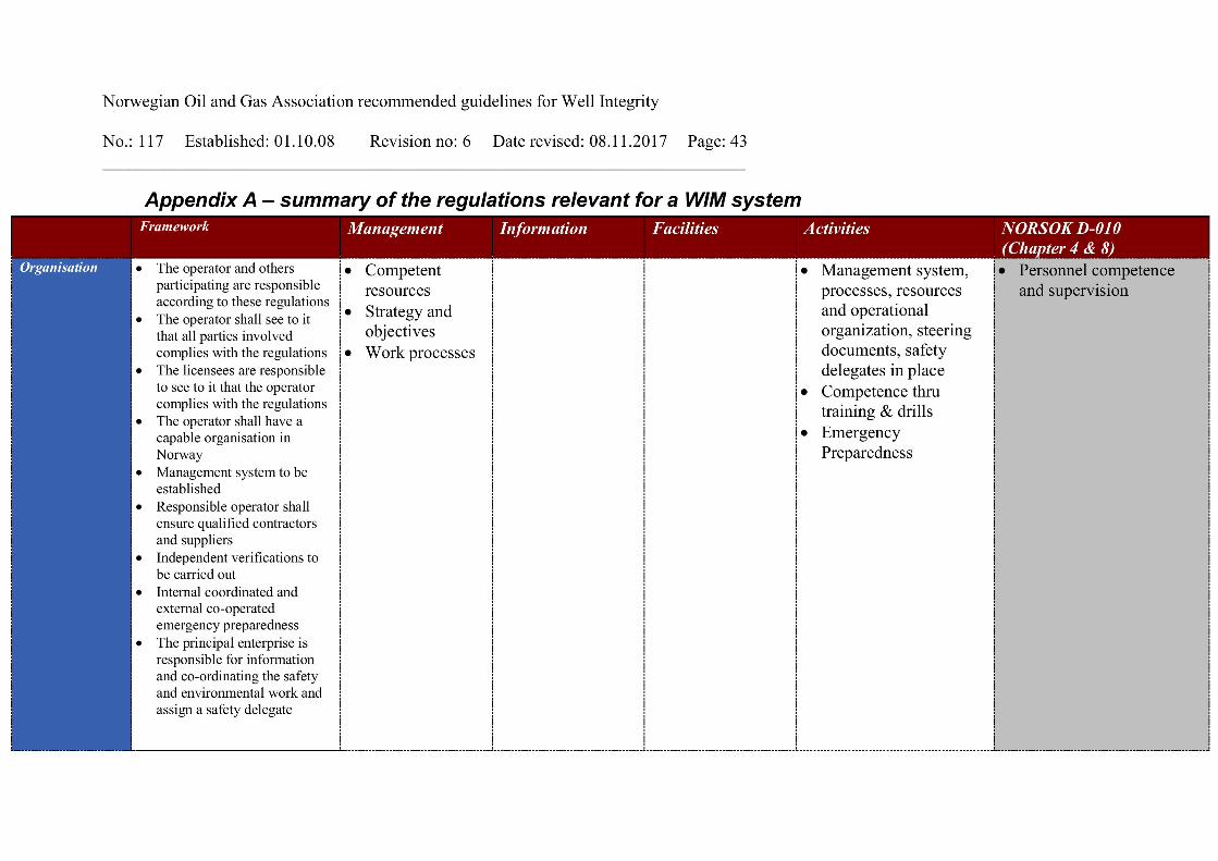
Norwegian Oil and Gas Associa tion recommended g uidelines for Well Integrity
No.: 117 Established : 01.10.08 Revision no: 6 Date revised: 08.11.2017 Page: 43__________________________________________________________________________
Appendix A – summary of the regulations relevant for a WIM systemFramework Management Information Facilities Activities NORSOK D - 010
(Chapter 4 & 8)Organisation • The operator and others
participating are responsibleaccording to these regulations
• The operator shall see to itthat all parties involvedcomplies with the regulations
• The licensees are responsibleto see to it that the operatorcomplies with the regulations
• The operator shall have acapable organisation inNorway
• Management system to beestablished
• Responsible operator shallensure qualified contractorsand suppliers
• Independent verifications tobe carried out
• Internal coordinated andexternal co - operatedemergency preparedness
• The principal enterprise isresponsible for informationand co - ordinati ng the safetyand environmental work andassign a safety delegate
• Competentresources
• Strategy andobjectives
• Work processes
• Management system,processes, resourcesand operationalorganization, steeringdocuments, safetydelegates in place
• Competence thrutraining & drills
• EmergencyPreparedness
• Personnel competenceand supervision

Norwegian Oil and Gas Associa tion recommended g uidelines for Well Integrity
No.: 117 Established : 01.10.08 Revision no: 6 Date revised: 08.11.2017 Page: 44__________________________________________________________________________
Framework Management Information Facilities Activities NORSOK D - 010(Chapter 4 & 8)
Design • HSE assessment and ALARPprinciple to be followed
• Design, engineering andmanufacture for the wholelife cycle, including removal.
• Wells to be placed in safedistance from activities andfacilities so that they will notconstitute an unacceptablerisk
• Technicalstandards
• Barriers
• Verifiablebarriers
• Robust welldesign
• Independent,fail - safe safetysystem
• Surface and sub -surface ESDvalves
• Design againstcyclic andchanging loads(conductor andsurface casing?)
• Well barrier purpose• Well barrier design and
construction principles• Well design process for
new wells, alterations andchanges to existing wells
• Basis of design• Load case s scenarios and
design factors• Annulus B design and
monitoring ability for gaslift and multi - purposewells
OperationalProcedures
• Petroleum activities shall besafe and prudent. A high levelof HSE shall be establishedand maintained.
• In the early phase, descriptionof the well integritymanagement system andbarrier philosophy for the lifecycle of the wells shall bedescribed.
• Authorities may makeexemptions from theregulations
• Barriers• Monitoring and
verification
• Operate within thedesign load limits
• Procedures in place toprevent faults
• Procedures forbypassing safetysystems
• Monitoring of criticalparameters (barrierstatus, …)
• Well barrier acceptancecriteria and function
• Verification (leak orfunction testing,including documentation)
• Well barri er monitoringand impairment
• Well barrier re -establishment

Norwegian Oil and Gas Associa tion recommended g uidelines for Well Integrity
No.: 117 Established : 01.10.08 Revision no: 6 Date revised: 08.11.2017 Page: 45__________________________________________________________________________
Framework Management Information Facilities Activities NORSOK D - 010(Chapter 4 & 8)
• Transfer ofInformation (handover,...)
• Address workingenvironment issues
• Maintenanc e Programbased on equipmentcriticality
• EmergencyPreparednessProcedures
• Well program• Well Control• Testing/maintaining
well barriers
• Activity and operationsshut downcriteria/situations
• Activity programs andprocedures
• Contingency plans (blow -outs and relief wells)
• Production/injectionwithin the operationalboundaries and measuresif they are exceeded
• Control of sandproduction
• Scale/asphaltenesproblems
• Hydrate preventionData system • Material and information to
be available to documentcompliance
• HSE information shall beavailable and public sharedwhen requested
• Representative data on naturalconditions to be gathered andused.
• Data gathering• Indicators
showing risklevel etc
• Non -conformances
• Data retention• Daily reports• Incidents and
accidentsreporting
• Critical parameterseasily available
• Well data will becollected
• Well barrier schematics• Documentation and
reporting• Handover documentation

Norwegian Oil and Gas Associa tion recommended g uidelines for Well Integrity
No.: 117 Established : 01.10.08 Revision no: 6 Date revised: 08.11.2017 Page: 46__________________________________________________________________________
Framework Management Information Facilities Activities NORSOK D - 010(Chapter 4 & 8)
Analysis • HSE to be further developed• ALARP principle to be
followed• Assessments shall be made in
all phases• PSA carries out supervision
and verifications• Management system to be
maintained and improved
• Risk• Follow up• Improvement
• Reportingincreased risk
• SIMOPS• Pre - Planning• Continuous
improvement of PM
• On - site risk assessment• SIMOPS

Norwegian Oil and Gas Association recommended guidelines for Well Integrity
No.: 117 Established: 01.10.08 Revision no: 6 Date revised: 08.11.2017 Page: 47 __________________________________________________________________________
6 Sustained casing pressure
6.1 Objective Sustained casing pressure has received increased attention the last years. There have been limited specific guidance and requirements available to assist the operators in the management of this challenge. WIF has created this document to enhance common industry understanding, functional recommendations and related best practices. The document focuses on management of sustained casing pressure both for platform and subsea wells and covers aspects such as monitoring, detection, evaluation, acceptance criteria and mitigating measures. Prevention and elimination of sustained casing pressure, including design of new wells and interventions in existing wells, is also reviewed although not in detail. Sustained casing pressure definition Sustained casing pressure (SCP) is defined as pressure in any well annulus that is measurable at the wellhead and rebuilds when bled down, not caused solely by temperature fluctuations or imposed by the operator.
6.2 Sustained casing pressure management
6.2.1 Monitoring and detection Sustained casing pressure (SCP) can arise for a variety of causes, including degradation or failure of well barriers, and can occur throughout the life time of the well. Appropriate monitoring and routines to aid early detection of sustained casing pressure is therefore an important part of the management of SCP. NORSOK D-010 states that pressures in all accessible annuli shall be monitored and maintained within minimum and maximum operational pressure range limits to verify that the integrity status of well barriers is known at all times. Well parameters such as temperatures and rates should also be monitored to facilitate correct interpretation of pressure trends and identification of abnormal pressure behaviour. During normal trouble-free operation the annuli pressures will show a clear and predictable dependency mainly on the well temperature, but also on pressures in adjacent annuli or tubing and flow rate.

Norwegian Oil and Gas Association recommended guidelines for Well Integrity
No.: 117 Established: 01.10.08 Revision no: 6 Date revised: 08.11.2017 Page: 48 __________________________________________________________________________
For example, during the start up of a producer, as the well is warmed up, it is expected that the annulus pressure for a liquid filled annulus increase. The opposite is expected when the same well is shut in. When the temperature and flow rate are stable the annuli pressures should also be stable. The expected annulus behaviour for injection wells will depend on the difference in temperature between the injection fluid and the surroundings of the well. For wells where the injection fluid has a lower temperature than the surroundings the annuli pressures can increase significantly when the well is shut in and the temperature increases.
After a start up of a well it is expected that the annulus pressures stabilize at the same values as before the well was shut in if no top ups or bleed downs have been done and the stabilized temperature is the same. Any deviations from the expected annulus pressure behaviour can indicate the presence of SCP. It can be difficult to detect the onset of SCP based on parameter behaviour over short time periods. Therefore assessments of parameter trends over longer time periods (e.g. months) are recommended to make it possible to identify slow pressure build up over time. Since the monitoring of well parameters is critical for several reasons, including SCP management, it is important that the monitored values are recorded with appropriate frequency and that they are representative and correct. NORSOK D-010 states states A-Annulus pressure for all wells and B-Annulus pressure for multi-purpose and annulus gas lift wells shall be monitored through continuous recording of the annulus pressure to verify the integrity of the well barrier. For multi-purpose and annulus gas lift subsea wells the B-annulus shall be designed to withstand the thermal pressure build-up if possible, otherwise an acceptable pressure management system shall be implemented. The ability to detect SCP will improve with increasing monitoring frequency. Therefore continuous remote monitoring of all accessible annuli is considered best practice. The quality of the recorded values should be appropriately ensured through regular calibration, inspection and function testing of the monitoring equipment.
Undesired events such as plugged lines, unintentionally closed valves and non-calibrated equipment will result in misinformation and misinterpretation of annulus pressure behaviour and increased risk of equipment failures due to excessive pressures.
Bleed downs and top ups should be recorded to facilitate:
• correct interpretation of annulus pressure behaviour, • detection of foreign fluids,
Norwegian Oil and Gas Association recommended guidelines for Well Integrity
No.: 117 Established: 01.10.08 Revision no: 6 Date revised: 08.11.2017 Page: 49 __________________________________________________________________________
• annulus content is known The minimum information that should be recorded is:
• annulus pressure before and after the activity • duration of the activity • the fluid type • volume introduced or removed from the annulus (if practical) • pressure behaviour of other annuli and tubing
The pressure ratings for equipment and lines used when bleeding down and topping up annuli should be verified to confirm suitability. If solids can be present in the fluids bled off or pumped potential erosion and plugging of the equipment and lines should also be considered. Operational annulus pressure limits should be based on the expected pressures during normal trouble free operation in addition to equipment limitations. Such basis for the operational annulus pressure limits can improve the possibility for detecting excessive and abnormal annulus pressures, and response time for such detections can be improved even further if deviations from the limits trigger automatic alarms. Operating wells with positive annuli pressures and differences in tubing and annuli wellhead pressures will facilitate detection of abnormal pressures. For further information about annulus pressure limits refer to section 6.3.2 Annulus pressure criteria. In special cases, where SCP is regarded as a field or installation challenge, it may be appropriate to initiate regular specific testing and inspection to facilitate early detection of SCP. Such testing and inspections can include:
• Performing and analyzing bleed downs to detect potential subsequent pressure build up and indications of abnormal annulus pressure behaviour
• Measurements of liquid level in annuli by echometer, top ups with volume control or other methods to detect changes in annuli content
• Sampling and analysis of annuli fluids to detect foreign fluids not intentionally placed in the annuli
• Direct measurements of leak rate to detect influx into annuli Some wells may have an inherent risk of undetected leak into annuli due to well designs or condition which preclude detection below certain depths through regular annulus monitoring. This can be e.g. well designs with packers between casings. Undetected leaks into annuli can have an escalation potential and may result in SCP. If such leaks are suspected, logging to detect potential flow behind casing as a proactive measure can be considered.

Norwegian Oil and Gas Association recommended guidelines for Well Integrity
No.: 117 Established: 01.10.08 Revision no: 6 Date revised: 08.11.2017 Page: 50 __________________________________________________________________________ 6.2.2 Evaluation If abnormal annulus pressure is detected, or if other information indicates the presence of SCP, an evaluation of the situation is required. The evaluation should investigate the nature of the leak, source, mechanism and location. This should include probability and consequences of loss of containment, in view of aspects such as leak rate, pressure and hydrocarbon gas volume and mass. These subjects will be discussed in the following subsections. During the evaluation activity the severity of the actual condition is unknown and due attention should be paid to identifying and addressing the potential risks.
Both safety of personnel involved and potential for escalation and aggravation of the condition should be included in this assessment, and the appropriate type and sequence of evaluation activities should be determined.
6.2.3 Evaluation of source, mechanism and location It is important to understand the source, mechanism and location of the leak path to optimize the management of SCP and properly assess the risk it constitutes. The reservoir which is the target of the actual wellbore can be the source, but shallower permeable zones can also act as sources for SCP. SCP can be a result of leaks e.g. through casing or tubing, through cement or through wellhead seals, but it can also be leaks directly from formation. The figure below (figure 6.1) illustrates some of the potential leak paths that can be present in a well. The figure is an example for illustrative purposes only.

Norwegian Oil and Gas Association recommended guidelines for Well Integrity
No.: 117 Established: 01.10.08 Revision no: 6 Date revised: 08.11.2017 Page: 51 __________________________________________________________________________
Figure 6-1: Examples of potential leak paths resulting in SCP
The first step in evaluation of potential SCP if abnormal annulus pressure behaviour has been observed should be to rule out any other causes and confirm the presence of SCP.
This can be done by annulus pressure manipulation, typically bleed downs or application of pressure, at stable well temperatures, e.g. with the well shut in. If pressure build up is observed at stable temperatures and no pressure is applied the presence of SCP can be regarded as confirmed.
An evaluation with adequate procedures should as far as possible assess all the potential leak paths as cause of SCP. Procedures will aid in ensuring all the potential sources and mechanisms are properly addressed and improve the probability of detecting if multiple leaks are causing the SCP.
Tubing Hanger Neck Seals
Tubing Hanger Pack-off Seals
Formation above Production
casing cement and casing
Tubing connections
Tubing Hanger Feed Through fittings
Production Packer
DHSV cylinder seals & connections
Reservoir
Casing connections
Seal assembly

Norwegian Oil and Gas Association recommended guidelines for Well Integrity
No.: 117 Established: 01.10.08 Revision no: 6 Date revised: 08.11.2017 Page: 52 __________________________________________________________________________ It is not uncommon that leaks resulting in SCP are leaks in one direction only and investigation of the leak direction should be included in the evaluation procedure. A procedure should also include evaluation of the annulus pressure behaviour for different relevant well conditions, e.g. shut in, flowing/injecting, on/off gas lift. In addition to the data gathered during the actual detection of abnormal annulus pressure behaviour there are several types of information related to both the well and the well construction which will improve the evaluation of SCP. These include:
• Information such as well construction diagrams and well barrier schematics can be used to identify potential leak paths
• Pore pressure plots and lithology columns will aid identification of possible sources • Determining the location of leaks by using pressure vs. depth plots for tubing and
relevant annuli • Historical monitoring and service data for the well, including well interventions
executed Normally the first step in evaluating the source, mechanism and location of leaks resulting in SCP is through systematic manipulation of the annulus pressure in question by bleeding off or applying pressure.
• Leaks to and/or from tubing or adjacent annuli may then be detected as dependency between pressures.
• Similarly pressures in tubing or adjacent annuli can be manipulated to assess leak direction.
• If the nature of the leak allows, the use of tracers can be applied to determine the location of the leak.
Fluid analysis of foreign fluid bled off from the annulus in question can provide valuable information on the source of the SCP. Fluid analysis can be used to distinguish e.g. reservoir fluid, fluid from shallower formations, injected water or gas, fluids intentionally placed in the annuli or foreign fluids. When the SCP can not be evaluated adequately using the methods and techniques described previously, logging to investigate leaks and detect potential flow behind casing can be considered.

Norwegian Oil and Gas Association recommended guidelines for Well Integrity
No.: 117 Established: 01.10.08 Revision no: 6 Date revised: 08.11.2017 Page: 53 __________________________________________________________________________ 6.2.4 Leak rate evaluation The potential consequences of SCP are closely related to the leak rate into the annulus and assessing the leak rate is a key part of the evaluation. Direct measurement of leak rate is the recommended practice when evaluating SCP, but this technique can be challenging when a multiphase mixture of gas and liquid is bled off. Another approach is to estimate leak rate based on pressure build up. Such estimations require information on annulus fluid content, annulus volume and temperature. Some of these parameters may be uncertain and due to the nature of the estimations it is recommended to make conservative assumptions. Options to reduce uncertainty in the estimations include topping up and confirming the annulus in question is liquid filled before recording pressure build or identifying liquid level using echometer or similar technology.
6.2.5 Annulus pressure evaluation The probability of failures and loss of containment due to SCP are closely related to the resulting excessive annulus pressures. Assessing the potential annulus pressures caused by SCP is therefore a key part of the evaluation. The annulus pressure can be evaluated through controlled pressure build up to investigate the potential maximum stabilised pressure.
During such assessments the maximum allowable annulus surface pressure for this activity should be clearly defined and regardless of stabilisation the pressure build up should be discontinued if this limit is approached. For further information about annulus pressure limits refer to section 6.3.2 Annulus pressure criteria.
As annulus pressure caused by SCP still will be affected by temperature the annulus pressure behaviour for different relevant well conditions, e.g. shut in, flowing/injecting, on/off gas lift, should be evaluated.

Norwegian Oil and Gas Association recommended guidelines for Well Integrity
No.: 117 Established: 01.10.08 Revision no: 6 Date revised: 08.11.2017 Page: 54 __________________________________________________________________________ 6.2.6 Hydrocarbon gas volume and mass evaluation The potential consequences of SCP are related to the volume and mass of flammable hydrocarbon gas stored in the annuli which can be released if containment is lost and assessing this volume and mass is a key part of the evaluation. Acoustic techniques, such as use of echometer, to identify the gas-liquid contact level in the annulus can be used to assess the hydrocarbon gas volume stored in the annuli. Bleeding of all gas in the annulus and subsequently topping up the annulus with liquid while monitoring the volume required to top up the annulus is another approach that can be used to determine the volume of hydrocarbon gas stored in the annulus. Although the methods described above can be used to assess the volume of hydrocarbon gas present in the annulus the main parameter is the mass of hydrocarbon gas present.
The mass of hydrocarbon gas can be estimated based on the volume of gas, the annulus pressure and gas properties. Some of these parameters may be uncertain and due to the nature of the estimations it is recommended to make conservative assumptions.
The volume of free hydrocarbon gas present in the annulus depends on pressure, as gas will be dissolved in liquids at higher pressures and will be liberated when pressure is decreased. It is therefore good practice to perform assessment of hydrocarbon gas volume at different annulus pressures to determine potential free hydrocarbon gas volumes at standard conditions.
6.2.7 Escalation potential evaluation In addition to the factors described previously a full evaluation of SCP includes the assessment of the escalation potential. This assessment involves the escalation potential for the leak resulting in SCP itself and its potential consequences and the incremental risk the condition may lead to for the well and the installation. In this respect information of the mechanism and source resulting in SCP has an important role. Some mechanisms, such as corrosion and erosion, can result in increasing leak rates over time and they can also introduce risk of degradation of equipment exposed to the fluid leaking into the annulus. These effects will most likely be magnified by bleed downs of the annulus pressure. The leak rate directly from the source can also increase over time dependant on the flow potential. The leak and the foreign fluid introduced to the annulus can also in some cases result in unusual load scenarios, not examined in the initial well design. The change in loads caused by SCP, combined with the potential degradation of the equipment exposed to the loads, should therefore be assessed as part of the evaluation.

Norwegian Oil and Gas Association recommended guidelines for Well Integrity
No.: 117 Established: 01.10.08 Revision no: 6 Date revised: 08.11.2017 Page: 55 __________________________________________________________________________ Although infrequent, there may be a risk of introduction of toxic material such as H2S or radioactive agents into annuli through SCP. Such materials implies a considerable risk to personnel safety and it should be verified that no such potential is present as part of the evaluation. It is a regulatory requirement that it shall be possible to secure a well in the event of any failure. The presence of SCP may complicate the securing of the well in the event of failures and limit the opportunity and availability for such activities. The plans for securing the well should therefore be reviewed and, if required, revised based on the evaluation. In addition to a potential increase in the total risk associated with the well which experiences SCP the condition may also result in increase in risk of escalation due to equipment and wells located in the vicinity of the well in question. This includes both the potential of escalation related to loss of containment for the annulus with SCP and loss of containment for the annulus with SCP due to events in its vicinity. The escalation potential should be assessed when evaluating SCP and if appropriate the installation QRA should be revisited.
6.3 Acceptance Criteria Determination When SCP has been confirmed and evaluated the severity of the condition should be assessed through comparison with pre-defined acceptance criteria. The acceptance criteria should be risk based and prevent an unmanageable situation resulting in unacceptable consequences. In the area of SCP it is appropriate to define acceptance criteria for parameters such as leak rate, annulus pressure and hydrocarbon gas mass. Considerations which should be done for these are discussed in the following subsections. Although not discussed in detail in this document, it may also in some circumstances be appropriate to define acceptance criteria for combinations of these parameters and for aspects discussed under section 6.2.7 Escalation potential evaluation.
6.3.1 Leak rate criteria Excessive leak rates increase the consequences if containment is lost. The objective when determining acceptance criteria is therefore to identify a rate were a release will not result in unacceptable consequences and the probability of escalation is as low as reasonably practicable.

Norwegian Oil and Gas Association recommended guidelines for Well Integrity
No.: 117 Established: 01.10.08 Revision no: 6 Date revised: 08.11.2017 Page: 56 __________________________________________________________________________ The consequences of outflow to the environment if containment is lost are related to aspects such as the ability to normalize the situation, the energy released, the combustibility, its impact on the affected area and escalation potential. API RP 14B states acceptance criteria for leakage rate through a closed subsurface safety valve system. The acceptance criteria are:
• 15 scf/min (0.42m3/min) for gas • 0.4 litre/min for liquid
Through a closed subsurface safety valve system leakage rates below these acceptance criteria have been assessed to have acceptable and manageable consequences with regards to aspects described above if released to environment. Although the leak rate acceptance criteria specified in API RP 14B is not directly applicable for SCP, its reasoning may still be regarded as a relevant analogue for determining acceptance criteria for SCP. For leaks through well barrier elements, using leak rate acceptance criteria below the API RP 14B acceptance criteria is usually appropriate due to the escalation potential (cf. 5.3.4 Escalation potential criteria). Using acceptance criteria above the API RP 14B criteria is not regarded as appropriate for leaks through well barrier elements. It may, however, sometimes be appropriate to set acceptance criteria that exceed the API RP 14B criteria if it can be verified that no hydrocarbon is present in the source of influx. A leak in the completion above DHSV can serve as an example of a situation where it may be appropriate to determine acceptance criteria for leak rates exceeding the API RP 14B criteria. It should also be ensured that the determined acceptance criteria are aligned with the definitions and assumptions used in the installation QRA. With reference to Chapter 4 Well Integrity Well Categorization in Norwegian Oil and Gas Guideline 117 a well where a leak rate into an annulus exceeds the acceptance criteria should be categorized as Orange or Red, depending on the pressure conditions in this annulus.
6.3.2 Annulus pressure criteria Excessive annulus pressures increase the probability of failures resulting in loss of containment and potentially uncontrolled release. The objective when determining acceptance criteria for annulus pressure, maximum allowable annulus surface pressure at the wellhead (MAASP), is therefore to identify a pressure at which the probability of failure is as low as reasonably practicable and normal operation of the well is allowed.

Norwegian Oil and Gas Association recommended guidelines for Well Integrity
No.: 117 Established: 01.10.08 Revision no: 6 Date revised: 08.11.2017 Page: 57 __________________________________________________________________________ 6.3.3 Failure modes Several failure modes can arise due to excessive annulus pressures and these modes should be identified and evaluated when determining MAASP. Failure modes include:
• Failures of casing strings, tubing string or other equipment constituting the annulus in question
• Fracturing of open hole included in the annulus • Failure modes for the next outer annulus.
When determining MAASP for a specific annulus the following should be considered:
• Burst of the outermost tubular string (including associated equipment in the string) • Collapse of the innermost tubular string (including associated equipment in the string) • Leak test pressures of the tubular strings (including associated equipment in the string) • Formation strength for exposed open hole section in the annulus
Although fracturing of formation in some cases is an inherent part of annulus pressure management it should be considered when determining MAASP for an annulus where SCP is present. Uncontrolled cross flow can occur if annulus pressure is allowed to exceed the strength of other formations exposed in the annulus if the source of the SCP is leaks directly from a permeable formation. In such cases it is therefore relevant to understand and assess at which annulus pressure formations will fracture and set MAASP accordingly. The Facilities Regulations stipulate that failure of a component, a system or a single mistake should not lead to unacceptable consequences. When determining MAASP for an annulus where SCP is present it is therefore appropriate to consider the failure modes for the next outer annulus, in addition to the failure modes for the annulus in question. This will reduce the probability of multiple failures in the event annulus to annulus communication should occur.
6.3.4 Fluid densities When evaluating failure modes such as burst and collapse of tubular and other equipment the additional pressure differential created by the density difference for fluids in the annuli which the element separates can be significant.
Differences in fluid density will result in difference in hydrostatic pressure across the element, a difference which will increase with depth. Due attention should therefore be applied to the assumptions made for density of the fluids in the annuli. As the objective of the assessment is to define acceptance criteria and safe operational limits it is recommended that any assumptions made are conservative. In practice this can for example be to assume that fluid in the annulus which is being assessed has original density while the fluid in the adjacent annuli is degraded and has a lower density than originally.

Norwegian Oil and Gas Association recommended guidelines for Well Integrity
No.: 117 Established: 01.10.08 Revision no: 6 Date revised: 08.11.2017 Page: 58 __________________________________________________________________________ 6.3.5 Degradation of tubulars Observed or modelled degradation of initial properties should be considered and properties adjusted accordingly when determining the strength to be used for mechanical elements being assessed. Such degradation can be caused by phenomena such as corrosion, erosion and general wear. Measures to detect and quantify the presence or potential presence of degradation include downhole inspections and modelling.
6.3.6 Safety factors Acknowledging that the condition of mechanical equipment installed in a well and the loads they may be exposed to always will be subject to some uncertainty it is also recommended to include appropriate safety factors in the assessment of these elements. The safety factors should be based on the consequences of the failure and the extent of the previously mentioned uncertainty. Note also that when assessing the MAASP for an annulus it is recommended to assume that adjacent annuli will have no surface pressure, or even vacuum, as these are conservative approaches and realistic operational conditions.
6.3.7 Maximum operational pressure (MOP) In addition to an acceptance criteria for annulus pressure, MAASP, a maximum operational pressure (MOP) should also be defined for an annulus. The MOP will act as the upper limit for allowable pressures during the operation which is its area of application. The intention of the MOP is to reduce the probability of exceeding MAASP and providing appropriate response time to manage pressures which approach these acceptance criteria. The MOP should also allow normal trouble-free operation of the well. When defining MOP expected pressure build up in annuli caused by increased temperature during ESD should be considered.
• When injecting fluid with lower temperature than the surroundings increase in temperature and annuli pressure can be expected when the well is shut in
The relative and absolute difference between the MAASP and the MOP should be based on the response time it will provide and the response time required. The response time provided will depend on the observed and potential pressure build up caused by SCP while the response time required will depend on the ability to detect and react, i.e. reduce the pressure in a controlled manner, if pressures approach the MAASP. Reduction in required response time can be facilitated by measures such as remote monitoring and alarms for earlier detection and remote bleed down opportunities for more rapid reaction.

Norwegian Oil and Gas Association recommended guidelines for Well Integrity
No.: 117 Established: 01.10.08 Revision no: 6 Date revised: 08.11.2017 Page: 59 __________________________________________________________________________ Based on the above it is not inappropriate to define higher MOP for special activities, such as troubleshooting and well service operations, than for normal operations, if the response time required during the former activities is less than during normal operation. Most wells are designed for operation with zero annulus pressure and even some vacuum in annuli. However, for some well designs it may be required to define a minimum operational pressure to reduce risk of failures. This can be e.g. subsea wells where annulus pressures outside the A-Annulus can not be monitored or vented, which may make it necessary to implement a minimum A-Annulus operating pressure to avoid collapsing the production casing. When determining minimum operational pressures the same failure modes as examined for determination of MAASP should be considered, and similar assumptions should be applied. In general operating wells with modest positive annulus pressures are preferable.
6.3.8 Hydrocarbon gas mass If an annulus exhibits influx containing hydrocarbon gas the acceptance criteria for annulus pressure will also affect the potential hydrocarbon gas mass contained in the annulus. In such circumstances it should be verified that no conflict is present between the acceptance criteria for annulus pressure and the acceptance criteria for hydrocarbon gas mass contained in the annulus.
6.3.9 Degradation of tubulars With reference to Chapter 4 Well Integrity Well Categorization in Norwegian Oil and Gas Guideline 117 a well where an annulus pressure cannot be maintained below the acceptance criteria should be categorized as Orange, unless the acceptance criteria for leak rate is exceeded for the same annulus. If an annulus exhibits both pressure and leak rate exceeding their respective acceptance criteria the well should be categorized as Red.
6.4 Hydrocarbon gas mass criteria Excessive flammable hydrocarbon gas mass in annuli increase the consequences if containment is lost. The objective when determining acceptance criteria for hydrocarbon gas mass is therefore to identify a hydrocarbon gas mass which will result in limited consequences and as low as reasonably practicable probability of escalation if released. It should be ensured that the determined acceptance criteria are aligned with the definitions and assumptions used in the installation QRA.

Norwegian Oil and Gas Association recommended guidelines for Well Integrity
No.: 117 Established: 01.10.08 Revision no: 6 Date revised: 08.11.2017 Page: 60 __________________________________________________________________________ When an annulus exhibits influx containing hydrocarbon gas the acceptance criteria for annulus pressure will also affect the potential hydrocarbon gas mass contained in the annulus. It should therefore be verified that no conflict is present between the acceptance criteria for annulus pressure and the acceptance criteria for hydrocarbon gas mass contained in the annulus. When determining acceptance criteria for hydrocarbon gas mass it is appropriate to investigate analogue requirements that may be relevant.
This include blow down requirements, i.e. the gas mass allowed in a system before a blow down function is required, and the gas mass allowed above ASCSSV in wells with annulus gas lift on the installation. When determining acceptance criteria based on analogue requirements the reasoning for the analogue requirements should be assessed to ensure that it is applicable and valid for this use. Although not directly applicable an analogue requirement which may be relevant for determining acceptance criteria for hydrocarbon gas mass is NORSOK S-001 Technical Safety which states the following for functional requirements for blow down:
All pressure vessels and piping segments, which during shut down contain more than 1000kg of hydrocarbons (liquid and/or gaseous), shall be equipped with a depressurising system. For pressure vessels and piping segments without a depressurising system, containing gas or unstabilised oil with high gas/oil-ratio, the maximum containment should be considerably lower than 1000kg. Location of segment (enclosed or open area), risk of segment being exposed to a fire, consequence of rupture, etc. should be considered. From the above it should be noted that in general acceptance criteria for hydrocarbon gas mass may be more stringent for surface wells than for subsea wells. The probability and consequence of multiple loss of containment for annuli and tubing should be considered when determining acceptance criteria for hydrocarbon gas mass.
6.4.1 Escalation potential criteria Note that acceptance criteria for the aspects discussed under section 6.2.7 Escalation potential evaluation are not discussed in this section. This does not imply that any and all conditions are acceptable, but acknowledges that the assessment of severity will depend on a variety of conditions specific for the situation being considered. For these aspects it is therefore regarded as more appropriate to make them subject to individual assessments than setting pre-defined acceptance criteria.
Norwegian Oil and Gas Association recommended guidelines for Well Integrity
No.: 117 Established: 01.10.08 Revision no: 6 Date revised: 08.11.2017 Page: 61 __________________________________________________________________________ 6.4.2 Mitigating measures After SCP has been confirmed and evaluated, appropriate mitigating measures should be considered to reduce the incremental risk related to the condition. The measures should be selected based on the conclusions made during the evaluation process. Even if the SCP condition meets acceptance criteria, implementation of mitigating measures should be considered. Norwegian Activities regulations state that ”If a barrier fails, activities shall not be carried out in the well other than those intended to restore the barrier. “ This requirement is applicable for SCP conditions not meeting acceptance criteria where the leak causing SCP is through a well barrier element. If the leak causing SCP is not through a well barrier element the requirement should still be regarded as relevant. Both options to reduce the probability of failures and options to reduce the consequence of failures should be investigated with emphasis on reducing the probability of failure. Potential technical and operational measures to mitigate the risk related to SCP are discussed in the following subsections.
6.4.3 Technical Modifications can be done to annulus equipment such as valves and monitoring devices to reduce the risk related to SCP. Installation of additional valves can increase the manageability of annuli with SCP, especially during activities where it is required to connect to the annulus outlet. As previously mentioned in sections 6.2.1 Monitoring & Detection and 6.3.2 Annulus pressure criteria the use of measures such as remote monitoring, alarms and remote bleed down can reduce the probability of failures by facilitating earlier detection of excessive pressures and reducing the required response time to manage pressures. Remote monitoring and alarms also offers the opportunity to implement automatic functions such as automatic bleed down to reduce the probability of failures and automatic valve closure to reduce the consequence of failures. Another measure to reduce the risk related to SCP is installation of physical protection to protect critical equipment from mechanical damage, such as falling objects. Such measures include both protection of the annulus with SCP to reduce the probability of failures and protection of critical equipment in the vicinity of this annulus to reduce the consequence of failures.

Norwegian Oil and Gas Association recommended guidelines for Well Integrity
No.: 117 Established: 01.10.08 Revision no: 6 Date revised: 08.11.2017 Page: 62 __________________________________________________________________________ Pumping operations can in some cases, dependant of the cause of SCP, reduce the probability and the consequence of failures related to SCP. This is discussed in section 6.5.2 Pumping Operations.
6.4.4 Operational When SCP is confirmed and evaluated, the acceptance criteria for annulus pressure (MAASP) should be reviewed to ensure this condition is considered and the probability of failure is as low as reasonably practicable. As discussed in section 6.3.2 Annulus Pressure criteria the presence of SCP increases the criticality of some failure modes. In an annulus where SCP is present uncontrolled cross flow can occur if annulus pressure is allowed to exceed the strength of other formations exposed in the annulus and the strength of these formations should therefore be considered when determining MAASP. When SCP is present in an annulus this condition can also introduce the risk of multiple failures in the event annulus to annulus communication should occur. When determining the MAASP for such an annulus it is therefore appropriate to consider failure modes for the next outer annulus, in addition to the failure modes for the annulus in question. If the cause of SCP is related to tubing-to-annulus or annulus-to-annulus communication this communication should be considered when determining the MAASP for the annuli affected. In general, for annuli that communicate, the MAASP should be reset to the lowest MAASP of the annuli in communication. To mitigate the risks related to SCP it is also appropriate to review annulus pressure management procedures. When SCP is present bleed downs may be required to maintain the annulus pressure below the defined MOP. Additional bleed down considerations to consider when SCP is present are:
• Bleed downs may aggravate and escalate the SCP condition, especially in cases where mechanisms such as corrosion and erosion are involved
• Bleeding off liquids which is replaced by gas or lighter liquids can result in higher annulus pressures and increased hydrocarbon mass in annulus, and should be avoided
• Annulus pressure management procedures should be optimized to minimize the number of required bleed downs and liquid volume bled off
• Evaluate if annuli should be topped up regularly with liquid after bleed downs • When the SCP condition results in hydrocarbon gas in annuli the risk of hydrate
formation during bleed downs should also be addressed in the annulus pressure management procedures
Norwegian Oil and Gas Association recommended guidelines for Well Integrity
No.: 117 Established: 01.10.08 Revision no: 6 Date revised: 08.11.2017 Page: 63 __________________________________________________________________________
• Contingency plans to manage annulus pressure and bleed downs of annuli during periods where the regular surface systems are not available, e.g. during shut downs, should be developed
For injector wells, SCP can in some cases result in injection fluid exposure to tubular not originally intended for such exposure. In these cases the risk of further escalation can be mitigated by ensuring that the quality of the injection fluid is appropriate for all the materials exposed to it. Another mitigating measure which can be implemented is increased frequency for preventive maintenance. Such measures can be more frequent maintenance of annulus equipment such as valves and gauges to reduce the risk related to the annulus where SCP is present or more frequent maintenance of well barrier elements, including ROV inspections of subsea wells, to reduce the overall risk related to the well. In addition, as previously mentioned in section 6.2.1 Monitoring & Detection, regular specific testing and inspection can be initiated for annuli where SCP is present to monitor the development of the condition. Such testing and inspections can include:
• Performing and analyzing bleed downs to assess subsequent pressure build up and indications of changes in annulus pressure behaviour
• Measurements of liquid level in annuli by echometer, top ups with volume control or other methods to detect changes in annuli content
• Sampling and analysis of annuli fluids to detect changes to fluid composition • Direct measurements of leak rate to monitor development
If any changes or developments are identified the original evaluation of the condition should be re-assessed. For cases where it is suspected that formation strength is exceeded as a result of SCP, regular logging to investigate if uncontrolled cross flow is present can act as a measure to avoid escalation. As previously discussed in section 6.2.7 Escalation potential evaluation the presence of SCP may complicate securing the well in the event of failures and limit the opportunity and availability for such activities. An appropriate mitigating measure if SCP is present is therefore to review the plans for securing the well, including kill operations, and if required, revise the plan based on the assessment. To mitigate the incremental risk associated with SCP it should be ensured that measures are in place to control the activity in the vicinity of wells with this condition.
Such measures can include physical barriers and specific considerations in procedures for simultaneous operations.

Norwegian Oil and Gas Association recommended guidelines for Well Integrity
No.: 117 Established: 01.10.08 Revision no: 6 Date revised: 08.11.2017 Page: 64 __________________________________________________________________________
6.5 Sustained casing pressure prevention and elimination Ideally SCP should be eliminated subsequent to detection. However, in practice experience has shown that SCP can be very challenging to eliminate when first present. In the following subsections some techniques and methods for elimination of SCP are referred to. Aspects which should be considered and addressed to prevent SCP are also discussed. In general, measures to eliminate SCP should be placed as close to the source as possible, and the potential for the condition or the condition should be eliminated as early as possible. Note that the selection of methods and techniques referred to in these subsections are far from exhaustive and the absence of any product or company names is intentional.
6.5.1 Well design and operational considerations In general, the most effective way to prevent SCP is through an initial well construction process where the potential for SCP is identified and addressed. Formation zones which can give influx and pressure build up in annuli outside the established well barriers is often the most complex and challenging situations to manage and eliminate after SCP has occurred. It is crucial that such zones are identified and properly isolated. This includes isolation from formations which are permeable or can be fractured if exposed to the pressure from the influx zone in the casing section. Such isolation is usually achieved through use of setting agents, such as cement, or external packers. It is recommended to consider the setting depth of the casing shoes with regards to formation strength such that it can withstand any influx from deeper formations during the life of the well. Probability of leaks resulting in SCP can be minimized through designing and selecting equipment which will operate as intended and withstand the environment it may be exposed to over time. To ensure that this objective is met, effort should be made to identify all the potential loads and environments the equipment may be exposed to during its service life. This applies for equipment installed during initial construction of the well, but also for equipment that is installed later in the life of the well, e.g. straddles, patches and plugs. Subsequent to construction of the well, parameters should be measured, monitored and evaluated during operation to ensure that the well is operated within the limitations of its design.

Norwegian Oil and Gas Association recommended guidelines for Well Integrity
No.: 117 Established: 01.10.08 Revision no: 6 Date revised: 08.11.2017 Page: 65 __________________________________________________________________________ Operating the well outside its design limits can promote degradation and failures, resulting in SCP and other undesired conditions. Relevant parameters which should be monitored and maintained within design limitations include flow rates, pressures, temperatures and fluid composition, especially water cut, content of solids and content of corrosive agents such as H2S, CO2 and O2. Appropriate alarm functions, and in some cases stop criteria, should be used to detect and manage parameters outside the design limitations. Special attention should be given to degradation mechanisms such as corrosion and erosion, which can be monitored through use of representative surface samples (e.g. probes, coupons) and downhole inspection such as calliper. When considerable changes to the service of the well is introduced, e.g. conversion of oil producer well to water injection or introduction of annulus gas lift to a well which was not originally designed for gas lift, a full design review should be performed to assess the suitability of the well for its new service.
Consideration should be given to acquire further information relating to the condition of the well.
For injectors it should be ensured that the planned well construction is adequate for the maximum expected injection pressure and that the maximum injection pressure reflects the actual well construction. In addition to equipment limitations the strength of any cap rock and strength or permeability of shallower formations that may be exposed to injection pressure should be evaluated when determining the maximum injection pressure.
This will reduce the risk of out of zone injection. One of several risks related to out of zone injection is SCP for the injection well in question and for wells in the vicinity of this well.
To prevent degradation and failures resulting in SCP or other undesired conditions, procedures should be developed to avoid unnecessary loading of the well. Activities where such loading can be considerable and should be controlled include start up and shut in of wells, situations where the well is exposed to significant changes in pressure and temperature over a relatively short time period.
Norwegian Oil and Gas Association recommended guidelines for Well Integrity
No.: 117 Established: 01.10.08 Revision no: 6 Date revised: 08.11.2017 Page: 66 __________________________________________________________________________ 6.5.2 Pumping operations When SCP has been discovered pumping operations are often used in an attempt to mitigate or eliminate the condition. Pumping operations can involve circulation, annular injection and pumping without annular injectivity. Such operations can involve placement of a setting agent and/or a heavy liquid in the annuli. Setting agents are used to isolate the source and location of SCP. In applications where setting agents are used to isolate the leaks resulting in SCP the agent is often placed above the location of the leak point. Consequently, the agent does not seal the leak itself and does not eliminate the source, but isolates it from the surface through this annulus. The source of SCP and its potential should therefore be properly evaluated and understood before it is isolated. In these applications the equipment, formations and overall well configuration located below the depth of the setting agent should be assessed to ensure that the source will be isolated properly over time and that a single failure will not lead to escalation and unacceptable consequences. Special attention should be given to the strength and permeability of the formations and sealing agent behind casing (e.g. cement) that can be exposed to the leak resulting in SCP below the depth of the setting agent. The combination of a leak and formation with non-negligible permeability or strength below the potential pressure build up caused by the leak can result in undetected uncontrolled crossflow. If the source of SCP cannot be isolated from the surface without introducing potential for leaks below the depth of the setting agent, the use of such agents is not adviseable and other solutions should be considered. Heavy liquids are used to hydrostatically control the source of SCP by creating hydrostatic overbalance. Such applications are usually preferred when the source of SCP is shallow permeable zones or when the leak resulting in SCP is leak in one direction only. If such applications are used for permeable zones with non-negligible permeability, or for other sources and mechanisms, the placement of heavy liquid should be combined with placement of fluid loss control agent in front of (below) the heavy liquid. The fluid loss control agent will aid the placement and efficiency of the heavy liquids over time and promote prolonged overbalanced conditions.

Norwegian Oil and Gas Association recommended guidelines for Well Integrity
No.: 117 Established: 01.10.08 Revision no: 6 Date revised: 08.11.2017 Page: 67 __________________________________________________________________________ When performing pumping operations the pressure loads the equipment in the annuli is exposed to should be assessed.
Both the differential pressure variations with time and with depth should be evaluated and appropriate pressure limits should be defined before the operation commences.
The pressure ratings for equipment and lines used when pumping should be verified to confirm suitability. If solids can be present in the fluids pumped potential erosion and plugging of the equipment and lines should also be considered. If circulation is available for the pumping operation it is preferable to circulate the setting agent and/or heavy liquid as this approach in general gives improved placement control and displacement. The possibility to circulate can also offer the opportunity to repeat the pumping operation if attempts are unsuccessful. During pumping operations with annular injection it is required to inject fluid into formation. To optimize and ensure proper placement in such operations the relevant formations should be assessed to understand which formation the fluid will be injected into and how this formation will behave during and subsequent to injection. When neither circulation nor annular injection is possible, bleed and lubrication can be used to place setting agent or heavy liquid in the annulus. This technique depends on bleeding off fluid from the annulus in question and subsequently pumping into the annulus. When bleed and lubrication is used to place heavy liquid in the annulus, improvement of the condition can be expected as long as the fluid removed from the annulus is lighter than the liquid pumped into it and this liquid remains in the annulus (see use of fluid loss control agents above).
In general the progress during bleed and lubrication activities is slow and decreasing with time. The technique does therefore not readily lend itself to use of setting agents as it is generally time consuming and the risk of premature setting and improper placement can be considerable.

Norwegian Oil and Gas Association recommended guidelines for Well Integrity
No.: 117 Established: 01.10.08 Revision no: 6 Date revised: 08.11.2017 Page: 68 __________________________________________________________________________ 6.5.3 Workover and interventions Several options are available to mitigate or eliminate SCP through the use of workover or conventional well interventions if the leak resulting in SCP is located in the completion string and the casing strings. When performing a workover, the completion string is replaced and casing strings become accessible for inspection and repair. Patches, straddles or similar mechanical isolation devices conveyed using conventional intervention techniques can be used to eliminate leaks in the completion and casing strings. Annulus interventions, conveying pipe and tools directly into annuli, can offer several opportunities to manage, mitigate and eliminate SCP. However, currently such technology is not in conventional use, and the current solutions have limitations. The main risks and challenges related to the current solutions for annulus interventions include:
• Pressure control – Working safely on live annuli • Stuck pipe – Often uncertain or unknown restrictions and clearance • Maximum operational depths – Limited by restrictions, clearance and annulus
configuration, risk of buckling and lock-up • Pumping rates and pressures – Low clearance necessitates small pipe, which results in
high pressures and low rates for pumping operations
7 HIGHLIGHTING CHANGES Changes made, revision 6 (October 2017): Chapter 4: Well Integrity well categorization is revised Numbering of the different chapters are updated Introduction Abbreviations and definitions Some minor administrative changes (wording) have been done