1160 Stereo Power Amplifier -...
25
1160 Stereo Power Amplifier Boulder Amplifiers, Inc. 255 S. Taylor Ave. Louisville, CO 80027 (303) 449-8220 www.boulderamp.com 03/01/2018 Rev. 1.0 P/N: 91055
Transcript of 1160 Stereo Power Amplifier -...

1160 Stereo Power Amplifier
Boulder Amplifiers, Inc.255 S. Taylor Ave.Louisville, CO 80027(303) 449-8220www.boulderamp.com
03/01/2018Rev. 1.0
P/N: 91055

AboutAbout Boulder Amplifiers, Inc.
Boulder was founded in 1984 and is the last high-performance audio manufacturer operating in North America to still perform all of its own design, engineering and manufacturing in-house. While this form of production may be more costly than outsourcing, the resulting quality control and reliability of the finished products are never compromised.
In 2016, Boulder moved into a new, purpose-built production facility to increase manufacturing efficiency and offer space for expansion to meet the needs of future growth.

Thank YouCongratulations and thank you for selecting the Boulder 1160 Stereo Power Amplifier for your high-performance sound system. We are certain it will provide you with many years of listening pleasure.
The 1160 represents the concerted efforts of numerous Boulder designers, engineers, and technicians working to bring you the best audio playback components in the world. This amplifier is among the best that Boulder has to offer.
Please take a few minutes to read through this instruction manual prior to using your 1160. This will help you understand the many functions and capabilities of the amplifier. It will also allow you to maximize the exceptional performance for which it was designed.
Your Boulder 1160 Stereo Power Amplifier has undergone extensive laboratory tests for safety, functionality, and technical excellence. In addition, it has been individually subjected to rigorous listening trials in our sound room utilizing a wide range of musical material. No product ever leaves our factory until we are totally satisfied that it achieves its full potential.
Table of ContentsGetting Started Placement of the 1160 Stereo Power Amplifier • • • • • • • • • • • • • • • • • • • • • • • • • • • 1-1 Connecting to the AC Mains Outlet • • • • • • • • • • • • • • • • • • • • • • • • • • • • • • • • • • • • • 1-1 Connecting to a Network • • • • • • • • • • • • • • • • • • • • • • • • • • • • • • • • • • • • • • • • • • • • • • 1-3 Connecting to a Balanced Source • • • • • • • • • • • • • • • • • • • • • • • • • • • • • • • • • • • • • • 1-3 Connecting to an Unbalanced Source • • • • • • • • • • • • • • • • • • • • • • • • • • • • • • • • • • • 1-3 Polarity • • • • • • • • • • • • • • • • • • • • • • • • • • • • • • • • • • • • • • • • • • • • • • • • • • • • • • • • • • • • • 1-5 Connecting Your Loudspeakers • • • • • • • • • • • • • • • • • • • • • • • • • • • • • • • • • • • • • • • • 1-5 Operation Powering Up • • • • • • • • • • • • • • • • • • • • • • • • • • • • • • • • • • • • • • • • • • • • • • • • • • • • • • • • 2-1 Input DC Offset Voltage Detection • • • • • • • • • • • • • • • • • • • • • • • • • • • • • • • • • • • • • • 2-3 Clip Detection • • • • • • • • • • • • • • • • • • • • • • • • • • • • • • • • • • • • • • • • • • • • • • • • • • • • • • • 2-3 Thermal Protection • • • • • • • • • • • • • • • • • • • • • • • • • • • • • • • • • • • • • • • • • • • • • • • • • • • 2-3 Maintenence • • • • • • • • • • • • • • • • • • • • • • • • • • • • • • • • • • • • • • • • • • • • • • • • • • • • • • • • 2-4
Remote Control Remote Operation • • • • • • • • • • • • • • • • • • • • • • • • • • • • • • • • • • • • • • • • • • • • • • • • • • • • 3-1
Fault Conditions Errors Requiring Boulder Dealer Service • • • • • • • • • • • • • • • • • • • • • • • • • • • • • • • • 4-1 Operational Errors • • • • • • • • • • • • • • • • • • • • • • • • • • • • • • • • • • • • • • • • • • • • • • • • • • • 4-1
Appendix Specifications • • • • • • • • • • • • • • • • • • • • • • • • • • • • • • • • • • • • • • • • • • • • • • • • • • • • • • • 6-1 Weights & Dimensions • • • • • • • • • • • • • • • • • • • • • • • • • • • • • • • • • • • • • • • • • • • • • • • • 6-2 Troubleshooting • • • • • • • • • • • • • • • • • • • • • • • • • • • • • • • • • • • • • • • • • • • • • • • • • • • • • • 6-3 Notes • • • • • • • • • • • • • • • • • • • • • • • • • • • • • • • • • • • • • • • • • • • • • • • • • • • • • • • • • • • • • • • 6-4


1-1
Get
ting
Star
ted
Getting StartedPlacement of the 1160 Stereo Power Amplifier
Your Boulder 1160 Stereo Power Amplifier is designed to reduce interference from external magnetic and radio fields (RF). While placement is not critical, known magnetic fields should be avoided.
Moving this component will require at least four people, as it is very heavy. Professional movers are recommended.
The 1160 Stereo Power Amplifier will generate some heat. Therefore, it should be located in an area with ample air circulation. Specifically, be certain that the heat sinks are unobstructed by objects that could potentially block airflow. Do not place the amplifier on deep carpet and be sure that the amplifier has a minimum of 3 inches (8 cm) of free airspace on all sides.
You may want to have access to the rear panel for cable changes.
Although input cables can be as long as necessary, it is suggested that speaker cables be as short as possible.
Connecting to the AC Mains Outlet
Your 1160 Stereo Power Amplifier is supplied with a mains power cable suitable for the location where it was purchased. It is constructed of large enough wire gauge and a plug appropriate for your AC line voltage. Do not substitute another power cable.
Exact voltage and frequency compatibility is stated in the specifications section. See page 6-1.
Once the 1160 Stereo Power Amplifier is connected to a live mains outlet and the rear panel switch is moved to the “On” position, the LED on the front panel will illuminate red for a short time. During this time the 1160 is booting up.
The LED will then pulse white on and off, indicating that the supervising microprocessor is powered up and the amp is ready to be turned on.

1-2
Getting Started
Getting Started

1-3
Get
ting
Star
ted
Getting StartedConnecting to a Network
In order for the 1160 to download software updates as necessary, it will need to be connected to a network with an active Internet connection.
Connect a network cable between the 1160 and a network router or switch. Use either Ethernet connector on the rear panel of the 1160; it does not matter which one you use.
Connecting to a Balanced Source
To fully realize the sonic potential of your 1160 Stereo Power Amplifier, always use balanced connections. Balanced cables minimize interference from magnetic and RF sources.
Connect the cables from your source or preamplifier outputs to the input connections provided on the rear panel of the 1160.
Connecting to an Unbalanced Source
Although the inputs are of the 3-pin XLR-type, an unbalanced source is easily accommodated by using a special cable. This cable has an RCA-type connector on the source end and a 3-pin XLR connector on the 1160 Stereo Power Amplifier end.
The negative input (pin 3) should be wired to ground only at the RCA connector. This brings the negative input reference of the 1160 to the unbalanced source ground, thus reducing loops.
Another option for accommodating unbalanced sources is the Boulder ABL2 Input Adapter. It converts a balanced input into an unbalanced RCA input at the rear panel of the 1160. Like the above cable, the negative input of the 1160 is connected to the ground of the RCA connector. However, the negative side will then share the shield wire with the chassis ground and will not have very good hum rejection.
Please contact your authorized Boulder dealer for further information about the ABL2 Input Adaptor.

1-4
Getting Started
Getting StartedConnecting to a Network
In order for the 1160 to download software updates as necessary, it will need to be connected to a network with an active Internet connection.
Connect a network cable between the 1160 and a network router or switch. Use either Ethernet connector on the rear panel of the 1160; it does not matter which one you use.
Connecting to a Balanced Source
To fully realize the sonic potential of your 1160 Stereo Power Amplifier, always use balanced connections. Balanced cables minimize interference from magnetic and RF sources.
Connect the cables from your source or preamplifier outputs to the input connections provided on the rear panel of the 1160.
Connecting to an Unbalanced Source
Although the inputs are of the 3-pin XLR-type, an unbalanced source is easily accommodated by using a special cable. This cable has an RCA-type connector on the source end and a 3-pin XLR connector on the 1160 Stereo Power Amplifier end.
The negative input (pin 3) should be wired to ground only at the RCA connector. This brings the negative input reference of the 1160 to the unbalanced source ground, thus reducing loops.
Another option for accommodating unbalanced sources is the Boulder ABL2 Input Adapter. It converts a balanced input into an unbalanced RCA input at the rear panel of the 1160. Like the above cable, the negative input of the 1160 is connected to the ground of the RCA connector. However, the negative side will then share the shield wire with the chassis ground and will not have very good hum rejection.
Please contact your authorized Boulder dealer for further information about the ABL2 Input Adaptor.
EthernetInput Input
1-5
Get
ting
Star
ted
Getting StartedPolarity
Please note that the 1160 Stereo Power Amplifier conforms to the AES standard of pin 2 as the “high,” “positive,” or “hot” pin for the balanced input.
The polarity of the 1160 Stereo Power Amplifier is such that a positive-going transition at pin 2 will produce a positive-going transition at the “+” output terminal.
Connecting Your Loudspeakers
Do not use a wrench or any other type of tool on the output terminal binding posts. Tighten these connectors by hand only.
WARNING: This is a high-powered amplifier! There is high voltage potential at the terminals when driven. Connections should only be made with the AC mains disconnected!
Select speaker cable spade terminals that will accept .250-inch (6 mm) diameter binding posts. Two sets of output connections are provided on the 1160 to enable easy bi-wiring. Because the binding posts are connected in parallel for each channel, there is no advantage of one set over the other.
There is no provision for the use of banana plugs. Banana plugs are proven to lose spring tension and come loose over time, increasing contact resistance and distortion. We also do not recommend the use of banana plugs at the speaker end for these reasons.

1-6
Getting Started
Getting Started

2-1
Ope
ratio
n
OperationPowering Up
With all connections made, you are ready to listen to your Boulder 1160 Stereo Power Amplifier.
To turn the amplifier on, slide the rear panel Master AC Switch to the ON position. The amplifier will go through a turn-on sequence, during which time the power LED will illuminate red.
The LED will then slowly pulse white on and off, indicating that the supervising microprocessor is powered up. At this time, press the front panel button to bring the unit out of Standby mode.
Because of the large inrush currents associated with the two large toroidal transformers, four power relays are used to turn on the amplifier. These are under control of the supervising ARM processor. During the power up sequence, you will hear two sets of two relay clicks, separated by intervals of two seconds.
Once powered up, the front panel LED will steadily glow white to indicate normal operation.
To turn the amplifier off, press the Standby button again. The indicator will then slowly and continuously change from white, to dark, and back to white. This indicates that the amplifier is in Standby mode.
NOTE: Because the 1160 greatly reduces power consumption when in Standby mode, it is only necessary to place the amplifier in Standby when not in use. You do not need to turn the 1160 off via the Master AC Switch on the rear panel. The 1160 was designed for years of operation in this manner and no damage to the unit will occur.
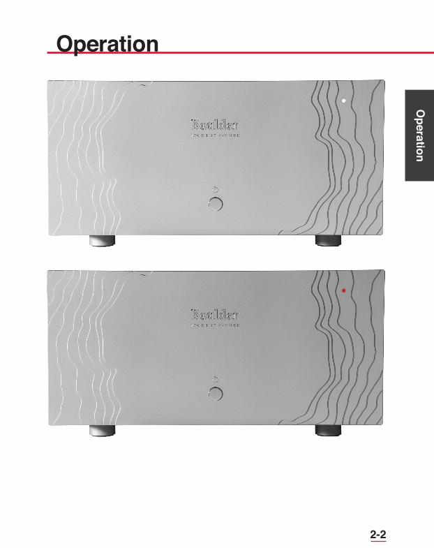
Power Off Power On
2-2
Operation
Operation

2-3
Ope
ratio
n
OperationInput DC Offset Voltage Detection
The Boulder 1160 is a direct-coupled power amplifier with a servo for zeroing out any DC voltage offset coming from the preamplifier or other sources connected to the amplifier’s input.
If the DC at the inputs is sufficient to cause three volts or more at the output terminals, a protection circuit will mute the amplifier’s output by electronically disconnecting the loudspeakers. The front panel LED will also turn red. This condition will continue until the source of DC is corrected or removed.
If the indicator remains red, it is recommended that the user correct the DC offset of the source device before continuing.
Clip Detection
Clipping of the waveform results when any amplifier is driven at too high a level. A clip detection circuit is included in the 1160 Stereo Power Amplifier.
The front panel LED will indicate clipping by momentarily turning from white to red. Both voltage and current modes of clipping are detected, although it is generally only voltage clipping that occurs.
Thermal Protection
A thermal protection circuit prevents high operating temperatures that are unpleasant to the touch and potentially harmful to the amplifier. A thermal cutout circuit will mute the amplifier when the transistor cases reach 85°C, and the front panel LED will turn red. If this happens, the output level of the system should be reduced and more ventilation should be provided for the amplifier.

2-4
Operation
Operation
Maintenance
No routine maintenance is required for the 1160 Stereo Power Amplifier. However, to keep operating temperatures at a minimum, be sure that the heat sink fins are not obstructed and remove any dust buildup that may occur.

3-1
Rem
ote
Con
trol
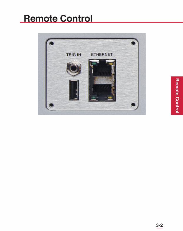
Remote ControlRemote Operation
Remote control and operation of the Boulder 1160 Stereo Power Amplifier is possible by the use of a 12V trigger, an external IP control system, or Boulder Net.
12V Trigger
The 1160 has a 1/8” minijack input connection on the rear panel for 12V triggering that will allow it to be turned On or Off. To complete the 12V trigger system, a single cable must be connected between the 1160 and a source component or preamplifier with a 12V trigger output connection. The 1160 supports both continuous and toggle 12V trigger commands.
External IP Control Systems
Modern home integration and automation systems are generally controlled through a home LAN (Local Area Network) via the use of IP (Internet Protocol) commands. When connected to a LAN, the 1160 is able to receive and respond to these commands through its Ethernet connection on the rear panel.
For further information about IP control and automation systems, please contact your authorized Boulder dealer.
Boulder Net
Boulder has developed an IP control system that is Open Home compliant and unique to Boulder products. When multiple Boulder products are all connected to a LAN, the Boulder Net system will allow you to turn various products on or off and control the functions of all connected components via an application that is downloadable to a mobile tablet or phone. Status messages can also be passed to Boulder products with a display.
For further information about Boulder Net, please see the Boulder Net Manual or visit www.boulderamp.com.
3-2
Rem
ote Control
Remote Control

4-1
Faul
t Con
ditio
ns
Fault ConditionsErrors Requiring Boulder Dealer Service
If the 1160 Stereo Power Amplifier will not turn on and the front panel LED blinks red, an error requiring dealer service has occurred. The indicator may flash red in a specific sequence to define its error code for an authorized Boulder technician.
If you are experiencing this problem with your 1160, contact your Boulder dealer immediately.
Operational Errors
At times the 1160’s front panel LED may flash red but continue operating normally. This is an Operational Error and indicates that there is a fault somewhere else in the system or in the use of the amplifier. Conditions that will be indicated as Operational Errors may include:
• DC offset at the input of the amplifier (from a source or preamplifier) • Thermal limit or safe operating temperature of the amplifier exceeded • Clipping of the output signal

4-2
Fault Conditions
Fault Conditions

6-1
App
endi
x
AppendixSpecifications
Continuous Power, Each ChannelWatts Ω THD 20-2kHz THD 20kHz
300 8 0.0008% 0.0040%300 4 0.0012% 0.0065%300 2 0.0018% 0.0100%
Peak Power, Each ChannelWatts Ω
300 8600 41200 2
Equivalent Input Noise (EIN), 20kHz BW 1.5 µV
Magnitude Response, 20 to 20KHz +0.00, -0.04 dB
Magnitude Response, -3dB at 0.015Hz, 200kHz
Voltage Gain 26dB
Input Impedance Balanced: 200kΩ,
Unbalanced 100kΩ
Common Mode Rejection (Balanced only) 60 Hz: 90dB,
10kHz: 70dB
Inputs 3-pin Balanced
Output Connectors 2 sets of 6 mm / .250 inch wingscrews
Power Requirements 100, 110-120, & 220-240 VAC
50-60 Hz, 250W nominal, 5000 W at maximum output
*All specifications taken at 240 VAC mains Power

6-2
Appendix
AppendixWeights and DimensionsAmplifier 135 lbs. (61.2 kg)
Shipping 215 lbs. (97.5 kg)
Amplifier Dimensions (Inches):
2.480 13.0401.475ROUND
DIA.
18.000
22.261
20.07521.558
8.3129.291
3.080 14.495
2.480 13.0401.475ROUND
DIA.
18.000
22.261
20.07521.558
8.3129.291
3.080 14.495
2.480 13.0401.475ROUND
DIA.
18.000
22.261
20.07521.558
8.3129.291
3.080 14.495

6-3
App
endi
x
AppendixTroubleshooting
SYMPTOM CAUSE REMEDYNo Power Indication Rear panel power
switch is not onTurn on power switch
Power amplifier is not plugged in
Connect to AC Mains outlet
Home circuit breaker is tripped
Have line voltage checked
Red power indication Low line voltage Reset breakers on rear panel
Defective power cable
Have cable tested
Defective power supply
Return to dealer for service
White power indication, but no sound from one channel
No signal from one channel of source
Check source controls, cables, and connections
One channel is muted by balance control
Re-center balance on preamp
No signal out to power amplifier
Check connections from preamplifier
Front panel LED flashes white and red and no output
Amplifier has detected a fatal error
Return to dealer for service

6-4
Appendix
AppendixNotes:
6-5
App
endi
x
Appendix
6-5
Notes:

6-6
Appendix
Appendix
6-6
Notes: