1136.8 15 EN
74
Thermal Oil / Hot Water Pump HPK-L Installation/Operating Manual
Transcript of 1136.8 15 EN

Thermal Oil / Hot Water Pump
HPK-L
Installation/Operating Manual

Legal information/Copyright
Installation/Operating Manual HPK-L
Original operating manual
All rights reserved. The contents provided herein must neither be distributed, copied, reproduced,edited or processed for any other purpose, nor otherwise transmitted, published or made available to athird party without the manufacturer's express written consent.
Subject to technical modification without prior notice.
© KSB SE & Co. KGaA, Frankenthal 06/10/2021
Contents
3 of 74HPK-L
Contents
Glossary .................................................................................................................................................. 6
1 General.................................................................................................................................................... 71.1 Principles ........................................................................................................................................................... 71.2 Installation of partly completed machinery.................................................................................................... 71.3 Target group..................................................................................................................................................... 71.4 Other applicable documents............................................................................................................................ 71.5 Symbols ............................................................................................................................................................. 71.6 Key to safety symbols/markings....................................................................................................................... 8
2 Safety...................................................................................................................................................... 92.1 General.............................................................................................................................................................. 92.2 Intended use ..................................................................................................................................................... 92.3 Personnel qualification and training............................................................................................................... 92.4 Consequences and risks caused by non-compliance with this manual ....................................................... 102.5 Safety awareness ............................................................................................................................................ 102.6 Safety information for the operator/user ..................................................................................................... 102.7 Safety information for maintenance, inspection and installation .............................................................. 102.8 Unauthorised modes of operation................................................................................................................ 112.9 Explosion protection ...................................................................................................................................... 11
2.9.1 Marking .............................................................................................................................................. 112.9.2 Temperature limits............................................................................................................................. 112.9.3 Monitoring equipment...................................................................................................................... 122.9.4 Operating limits ................................................................................................................................. 12
3 Transport/Storage/Disposal ................................................................................................................ 133.1 Checking the condition upon delivery .......................................................................................................... 133.2 Transport......................................................................................................................................................... 133.3 Storage/preservation...................................................................................................................................... 143.4 Return to supplier........................................................................................................................................... 153.5 Disposal ........................................................................................................................................................... 15
4 Description of the Pump (Set) ............................................................................................................. 164.1 General description ........................................................................................................................................ 164.2 Product information as per Regulation No. 1907/2006 (REACH)................................................................. 164.3 Designation..................................................................................................................................................... 164.4 Name plate...................................................................................................................................................... 164.5 Design details.................................................................................................................................................. 174.6 Configuration and function........................................................................................................................... 194.7 Noise characteristics ....................................................................................................................................... 204.8 Scope of supply............................................................................................................................................... 204.9 Dimensions and weights ................................................................................................................................ 21
5 Installation at Site ................................................................................................................................ 225.1 Checks to be carried out prior to installation............................................................................................... 225.2 Installing the pump set .................................................................................................................................. 22
5.2.1 Installation on the foundation.......................................................................................................... 235.2.2 Installation without foundation ....................................................................................................... 24
5.3 Piping .............................................................................................................................................................. 245.3.1 Connecting the piping....................................................................................................................... 245.3.2 Permissible forces and moments at the pump nozzles.................................................................... 265.3.3 Auxiliary connections......................................................................................................................... 27
5.4 Enclosure/insulation ....................................................................................................................................... 285.5 Checking the coupling alignment ................................................................................................................. 285.6 Aligning the pump and motor ...................................................................................................................... 30
5.6.1 Motors with adjusting screw............................................................................................................. 315.6.2 Motors without adjusting screw....................................................................................................... 31

Contents
4 of 74 HPK-L
5.7 Electrical connection ...................................................................................................................................... 325.7.1 Setting the time relay ........................................................................................................................ 335.7.2 Earthing .............................................................................................................................................. 335.7.3 Connecting the motor ....................................................................................................................... 33
5.8 Checking the direction of rotation................................................................................................................ 34
6 Commissioning/Start-up/Shutdown................................................................................................... 356.1 Commissioning/Start-up................................................................................................................................. 35
6.1.1 Prerequisites for commissioning/start-up ......................................................................................... 356.1.2 Filling in lubricants............................................................................................................................. 356.1.3 Shaft seal ............................................................................................................................................ 356.1.4 Quench liquid supply ......................................................................................................................... 366.1.5 Priming and venting the pump......................................................................................................... 366.1.6 Final check .......................................................................................................................................... 376.1.7 Cooling of the mechanical seal chamber ......................................................................................... 376.1.8 Heating up/keeping warm the pump (set)....................................................................................... 386.1.9 Start-up............................................................................................................................................... 386.1.10 Checking the shaft seal...................................................................................................................... 396.1.11 Shutdown ........................................................................................................................................... 39
6.2 Operating limits.............................................................................................................................................. 406.2.1 Ambient temperature........................................................................................................................ 406.2.2 Minimum permissible speed.............................................................................................................. 406.2.3 Frequency of starts............................................................................................................................. 416.2.4 Fluid handled ..................................................................................................................................... 41
6.3 Shutdown/storage/preservation .................................................................................................................... 426.3.1 Measures to be taken for shutdown ................................................................................................ 42
6.4 Returning to service ....................................................................................................................................... 43
7 Servicing/Maintenance........................................................................................................................ 447.1 Safety regulations........................................................................................................................................... 447.2 Servicing/Inspection........................................................................................................................................ 45
7.2.1 Supervision of operation ................................................................................................................... 457.2.2 Inspection work.................................................................................................................................. 477.2.3 Lubrication and lubricant change of rolling element bearings ..................................................... 48
7.3 Drainage/cleaning .......................................................................................................................................... 497.4 Dismantling the pump set.............................................................................................................................. 49
7.4.1 General information/Safety regulations........................................................................................... 497.4.2 Preparing the pump set..................................................................................................................... 507.4.3 Removing the motor.......................................................................................................................... 507.4.4 Removing the back pull-out unit ...................................................................................................... 507.4.5 Removing the impeller ...................................................................................................................... 517.4.6 Removing the plain bearing.............................................................................................................. 517.4.7 Removing the mechanical seals ........................................................................................................ 517.4.8 Dismantling the bearings .................................................................................................................. 527.4.9 Removing the plain bearing bush..................................................................................................... 53
7.5 Reassembling the pump set ........................................................................................................................... 537.5.1 General information/Safety regulations........................................................................................... 537.5.2 Installing the bearings ....................................................................................................................... 547.5.3 Installing the mechanical seal ........................................................................................................... 557.5.4 Fitting the plain bearing bush .......................................................................................................... 577.5.5 Fitting the bearing bracket ............................................................................................................... 587.5.6 Fitting the plain bearing .................................................................................................................. 587.5.7 Fitting the impeller ............................................................................................................................ 587.5.8 Fitting the back pull-out unit............................................................................................................ 597.5.9 Mounting the motor ......................................................................................................................... 59
7.6 Tightening torques......................................................................................................................................... 597.6.1 Tightening torques for volute casing/bearing bracket.................................................................... 59
7.7 Spare parts stock............................................................................................................................................. 607.7.1 Ordering spare parts.......................................................................................................................... 607.7.2 Recommended spare parts stock for 2 years' operation to DIN 24296 .......................................... 60

Contents
5 of 74HPK-L
7.7.3 Interchangeability of pump components......................................................................................... 61
8 Trouble-shooting.................................................................................................................................. 63
9 Related Documents .............................................................................................................................. 659.1 General assembly drawing with list of components .................................................................................... 65
10 EU Declaration of Conformity ............................................................................................................. 68
11 Certificate of Decontamination........................................................................................................... 69
Index ..................................................................................................................................................... 70

Glossary
6 of 74 HPK-L
1136
.8/1
5-EN
Glossary
Back pull-out designThe complete back pull-out unit can be pulled outwithout having to remove the pump casing fromthe piping.
Back pull-out unitPump without pump casing; partly completedmachinery
Certificate of decontaminationA certificate of decontamination is enclosed by thecustomer when returning the product to themanufacturer to certify that the product has beenproperly drained to eliminate any environmentaland health hazards arising from components incontact with the fluid handled.
Discharge lineThe pipeline which is connected to the dischargenozzle
Hydraulic systemThe part of the pump in which the kinetic energyis converted into pressure energy
Pool of pumpsCustomers/operators’ pumps which are purchasedand stored regardless of their later use.
PumpMachine without drive, additional components oraccessories
Pump setComplete pump set consisting of pump, drive,additional components and accessories
Suction lift line/suction head lineThe pipeline which is connected to the suctionnozzle

1 General
7 of 74HPK-L
1136
.8/1
5-EN
1 General
1.1 PrinciplesThis operating manual is valid for the type series and variants indicated on the frontcover.
The operating manual describes the proper and safe use of this equipment in allphases of operation.
The name plate indicates the type series and size, the main operating data, the ordernumber and the order item number. The order number and order item numberclearly identify the pump set and serve as identification for all further businessprocesses.
In the event of damage, immediately contact your nearest KSB service facility tomaintain the right to claim under warranty.
1.2 Installation of partly completed machineryTo install partly completed machinery supplied by KSB refer to the sub-sections underServicing/Maintenance. (ð Section 7.5.5, Page 58)
1.3 Target groupThis operating manual is aimed at the target group of trained and qualified specialisttechnical personnel. (ð Section 2.3, Page 9)
1.4 Other applicable documents
Table 1: Overview of other applicable documents
Document Contents
Data sheet Description of the technical data of the pump (set)
General arrangement drawing/outline drawing
Description of mating and installation dimensionsfor the pump (set), weights
Drawing of auxiliary connections Description of auxiliary connections
Hydraulic characteristic curve Characteristic curves showing head, NPSHrequired, efficiency and power input
General assembly drawing1) Sectional drawing of the pump
Sub-supplier product literature1) Operating manuals and other product literaturedescribing accessories and integrated machinerycomponents
Spare parts lists1) Description of spare parts
Piping layout1) Description of auxiliary piping
List of components1) Description of all pump components
Assembly drawing1) Sectional drawing of the installed shaft seal
For accessories and/or integrated machinery components observe the relevantmanufacturer's product literature.
1.5 Symbols
Table 2: Symbols used in this manual
Symbol Description
✓ Conditions which need to be fulfilled before proceeding with thestep-by-step instructions
⊳ Safety instructions
⇨ Result of an action
⇨ Cross-references
1 If agreed to be included in the scope of supply

1 General
8 of 74 HPK-L
1136
.8/1
5-EN
Symbol Description
1.
2.
Step-by-step instructions
NoteRecommendations and important information on how to handlethe product
1.6 Key to safety symbols/markings
Table 3: Definition of safety symbols/markings
Symbol Description
! DANGER DANGER This signal word indicates a high-risk hazard which, if not avoided,will result in death or serious injury.
! WARNING WARNING This signal word indicates a medium-risk hazard which, if notavoided, could result in death or serious injury.
CAUTION CAUTION This signal word indicates a hazard which, if not avoided, couldresult in damage to the machine and its functions.
Explosion protection This symbol identifies information about avoiding explosions inpotentially explosive atmospheres in accordance with EU Directive2014/34/EU (ATEX).
General hazard In conjunction with one of the signal words this symbol indicates ahazard which will or could result in death or serious injury.
Electrical hazard In conjunction with one of the signal words this symbol indicates ahazard involving electrical voltage and identifies information aboutprotection against electrical voltage.
Machine damage In conjunction with the signal word CAUTION this symbol indicatesa hazard for the machine and its functions.
2 Safety
9 of 74HPK-L
1136
.8/1
5-EN
2 Safety
! DANGER All the information contained in this section refers to hazardous situations.
In addition to the present general safety information the action-related safetyinformation given in the other sections must be observed.
2.1 General▪ This operating manual contains general installation, operating and maintenance
instructions that must be observed to ensure safe operation of the system andprevent personal injury and damage to property.
▪ Comply with all the safety instructions given in the individual sections of thisoperating manual.
▪ The operating manual must be read and understood by the responsible specialistpersonnel/operators prior to installation and commissioning.
▪ The contents of this operating manual must be available to the specialistpersonnel at the site at all times.
▪ Information and markings attached directly to the product must always becomplied with and kept in a perfectly legible condition at all times. This appliesto, for example:
– Arrow indicating the direction of rotation
– Markings for connections
– Name plate
▪ The operator is responsible for ensuring compliance with all local regulations nottaken into account.
2.2 Intended use▪ The pump (set) must only be operated in the fields of application and within the
use limits specified in the other applicable documents. (ð Section 1.4, Page 7)
▪ Only operate pumps/pump sets which are in perfect technical condition.
▪ Do not operate the pump (set) in partially assembled condition.
▪ Only use the pump (set) to handle the fluids described in the data sheet orproduct literature of the pump model.
▪ Never operate the pump (set) without the fluid to be handled.
▪ Observe the minimum flow rate and maximum flow rate indicated in the datasheet or product literature (to prevent overheating, mechanical seal damage,cavitation damage, bearing damage, etc).
▪ Always operate the pump (set) in the direction of rotation it is intended for.
▪ Do not throttle the flow rate on the suction side of the pump (to preventcavitation damage).
▪ Consult the manufacturer about any use or mode of operation not described inthe data sheet or product literature.
2.3 Personnel qualification and trainingAll personnel involved must be fully qualified to transport, install, operate, maintainand inspect the machinery this manual refers to.
The responsibilities, competence and supervision of all personnel involved intransport, installation, operation, maintenance and inspection must be clearlydefined by the operator.
Deficits in knowledge must be rectified by means of training and instructionprovided by sufficiently trained specialist personnel. If required, the operator cancommission the manufacturer/supplier to train the personnel.
Training on the pump (set) must always be supervised by technical specialistpersonnel.

2 Safety
10 of 74 HPK-L
1136
.8/1
5-EN
2.4 Consequences and risks caused by non-compliance with this manual▪ Non-compliance with these operating instructions will lead to forfeiture of
warranty cover and of any and all rights to claims for damages.
▪ Non-compliance can, for example, have the following consequences:
– Hazards to persons due to electrical, thermal, mechanical and chemicaleffects and explosions
– Failure of important product functions
– Failure of prescribed maintenance and servicing practices
– Hazard to the environment due to leakage of hazardous substances
2.5 Safety awarenessIn addition to the safety information contained in this operating manual and theintended use, the following safety regulations shall be complied with:
▪ Accident prevention, health regulations and safety regulations
▪ Explosion protection regulations
▪ Safety regulations for handling hazardous substances
▪ Applicable standards, directives and laws
2.6 Safety information for the operator/user▪ Fit protective equipment (e.g. contact guards) supplied by the operator for hot,
cold or moving parts, and check that the equipment functions properly.
▪ Do not remove any protective equipment (e.g. contact guards) during operation.
▪ Provide the personnel with protective equipment and make sure it is used.
▪ Contain leakages (e.g. at the shaft seal) of hazardous fluids handled (e.g.explosive, toxic, hot) so as to avoid any danger to persons and the environment.Adhere to all relevant laws.
▪ Eliminate all electrical hazards. (In this respect refer to the applicable nationalsafety regulations and/or regulations issued by the local energy supplycompanies.)
▪ If stopping the pump does not increase potential risk, fit an emergency-stopcontrol device in the immediate vicinity of the pump (set) during pump setinstallation.
2.7 Safety information for maintenance, inspection and installation▪ Modifications or alterations of the pump (set) are only permitted with the
manufacturer's prior consent.
▪ Use only original spare parts or parts/components authorised by themanufacturer. The use of other parts/components can invalidate any liability ofthe manufacturer for resulting damage.
▪ The operator ensures that maintenance, inspection and installation areperformed by authorised, qualified specialist personnel who are thoroughlyfamiliar with the manual.
▪ Only carry out work on the pump (set) during standstill of the pump.
▪ Only perform work on the pump set when it has been disconnected from thepower supply (de-energised).
▪ The pump (set) must have cooled down to ambient temperature.
▪ Pump pressure must have been released and the pump must have been drained.
2 Safety
11 of 74HPK-L
1136
.8/1
5-EN
▪ When taking the pump set out of service always adhere to the proceduredescribed in the manual. (ð Section 6.3, Page 42)
▪ Decontaminate pumps which handle fluids posing a health hazard. (ð Section 7.3, Page 49)
▪ As soon as the work has been completed, re-install and re-activate any safety-relevant devices and protective devices. Before returning the product to service,observe all instructions on commissioning. (ð Section 6.1, Page 35)
2.8 Unauthorised modes of operationNever operate the pump (set) outside the limits stated in the data sheet and in thismanual.
The warranty relating to the operating reliability and safety of the supplied pump(set) is only valid if the equipment is used in accordance with its intended use.(ð Section 2.2, Page 9)
2.9 Explosion protection
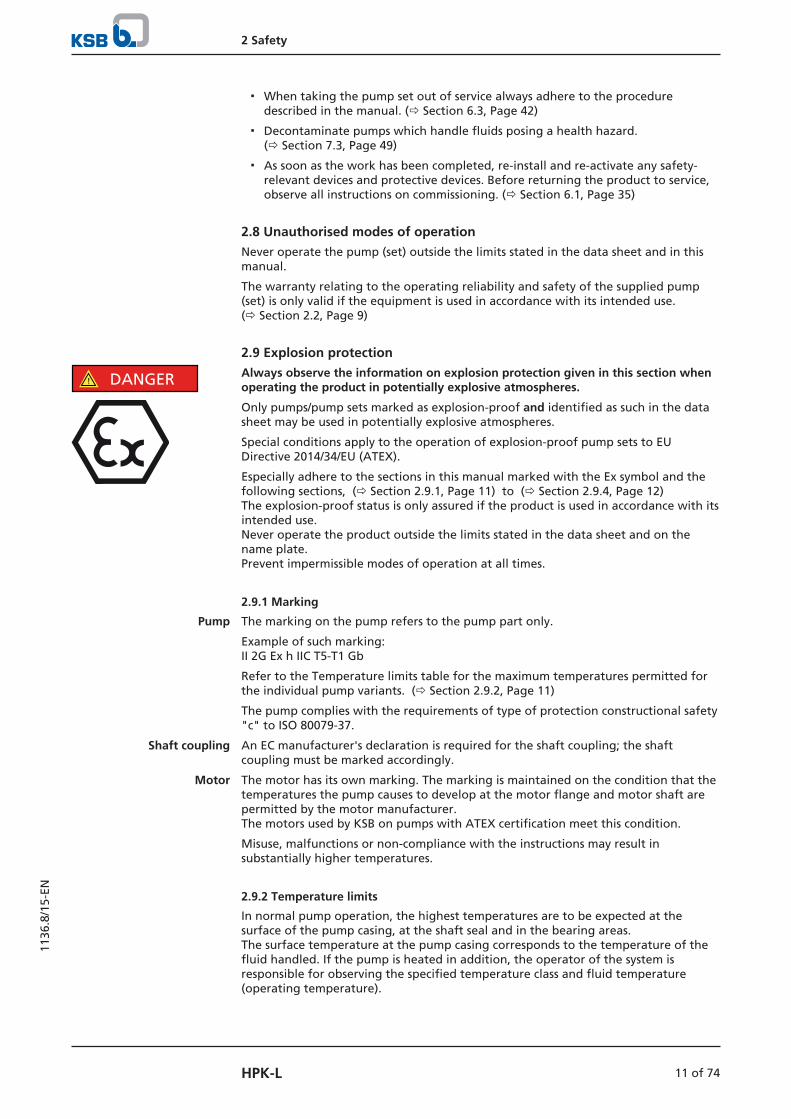
! DANGER Always observe the information on explosion protection given in this section whenoperating the product in potentially explosive atmospheres.
Only pumps/pump sets marked as explosion-proof and identified as such in the datasheet may be used in potentially explosive atmospheres.
Special conditions apply to the operation of explosion-proof pump sets to EUDirective 2014/34/EU (ATEX).
Especially adhere to the sections in this manual marked with the Ex symbol and thefollowing sections, (ð Section 2.9.1, Page 11) to (ð Section 2.9.4, Page 12) The explosion-proof status is only assured if the product is used in accordance with itsintended use. Never operate the product outside the limits stated in the data sheet and on thename plate.Prevent impermissible modes of operation at all times.
2.9.1 Marking
Pump The marking on the pump refers to the pump part only.
Example of such marking: II 2G Ex h IIC T5-T1 Gb
Refer to the Temperature limits table for the maximum temperatures permitted forthe individual pump variants. (ð Section 2.9.2, Page 11)
The pump complies with the requirements of type of protection constructional safety"c" to ISO 80079-37.
Shaft coupling An EC manufacturer's declaration is required for the shaft coupling; the shaftcoupling must be marked accordingly.
Motor The motor has its own marking. The marking is maintained on the condition that thetemperatures the pump causes to develop at the motor flange and motor shaft arepermitted by the motor manufacturer.The motors used by KSB on pumps with ATEX certification meet this condition.
Misuse, malfunctions or non-compliance with the instructions may result insubstantially higher temperatures.
2.9.2 Temperature limits
In normal pump operation, the highest temperatures are to be expected at thesurface of the pump casing, at the shaft seal and in the bearing areas. The surface temperature at the pump casing corresponds to the temperature of thefluid handled. If the pump is heated in addition, the operator of the system isresponsible for observing the specified temperature class and fluid temperature(operating temperature).

2 Safety
12 of 74 HPK-L
1136
.8/1
5-EN
The table (ð Table 4) lists the temperature classes and the resulting maximumpermissible fluid temperatures. The values shown correspond to the theoreticallimits. They include only a general safety margin for the mechanical seal. For singlemechanical seals, the safety margin required for specific operating conditions andmechanical seal designs may be substantially higher. If operating conditions differfrom those stated on the data sheet, or if different mechanical seals are used, theactual safety margin required needs to be determined individually. If in doubt pleasecontact the manufacturer.
The temperature class specifies the maximum permissible temperature at the surfaceof the pump set during operation.
For the permissible operating temperature of the pump in question refer to the datasheet.
Table 4: Temperature limits
Temperature class to ISO 80079-36 Maximum permissible fluid temperature2)
T1 Maximum 400 °C3)
T2 280 °C
T3 185 °C
T4 120 °C
T5 85 °C
T6 Only after consultationwith the manufacturer
Temperature class T5 Based on an ambient temperature of 40 °C and proper maintenance and operation,compliance with temperature class T5 is warranted in the area of the rolling elementbearings. If the ambient temperature exceeds 40 °C, contact the manufacturer.
Temperature class T6 A special design is required to comply with the requirements of temperature class T6in the bearing area.
Misuse, malfunctions or non-compliance with the instructions may result insubstantially higher temperatures.
If the pump is to be operated at a higher temperature, the data sheet is missing or ifthe pump is part of a pool of pumps, contact KSB for the maximum permissibleoperating temperature.
2.9.3 Monitoring equipment
The pump (set) must only be operated within the limits specified in the data sheetand on the name plate. If the system operator cannot warrant compliance with these operating limits,appropriate monitoring devices must be used. Check whether monitoring equipment is required to ensure that the pump setfunctions properly.
Contact KSB for further information about monitoring equipment.
2.9.4 Operating limits
The minimum flow rates indicated in (ð Section 6.2.4.1, Page 41) refer to waterand water-like fluids handled. Longer operating periods with these fluids and at theflow rates indicated will not cause an additional increase in the temperatures at thepump surface. However, if the physical properties of the fluids handled are differentfrom water, it is essential to check whether an additional heat build-up may occurand if the minimum flow rate must therefore be increased. The calculation formulain (ð Section 6.2.4.1, Page 41) can be used to check whether additional heat build-up may lead to a dangerous temperature increase at the pump surface.
2 Subject to further limitations for mechanical seal temperature rise3 Depending on the material variant

3 Transport/Storage/Disposal
13 of 74HPK-L
1136
.8/1
5-EN
3 Transport/Storage/Disposal
3.1 Checking the condition upon delivery1. On transfer of goods, check each packaging unit for damage.
2. In the event of in-transit damage, assess the exact damage, document it andnotify KSB or the supplying dealer and the insurer about the damage in writingimmediately.
3.2 Transport
DANGER
The pump (set) could slip out of the suspension arrangement
Danger to life from falling parts!
▷ Always transport the pump (set) in the specified position.
▷ Never attach the suspension arrangement to the free shaft end or the motoreyebolt.
▷ Observe the information about weights, centre of gravity and fastening points.
▷ Observe the applicable local accident prevention regulations.
▷ Use suitable, permitted lifting accessories, e.g. self-tightening lifting tongs.
To transport the pump/pump set or back pull-out unit suspend it from the liftingtackle as shown.
≤ 90 °
Fig. 1: Transporting the back pull-out unit
Fig. 2: Transporting the pump
3 Transport/Storage/Disposal
14 of 74 HPK-L
1136
.8/1
5-EN
≤ 90 °
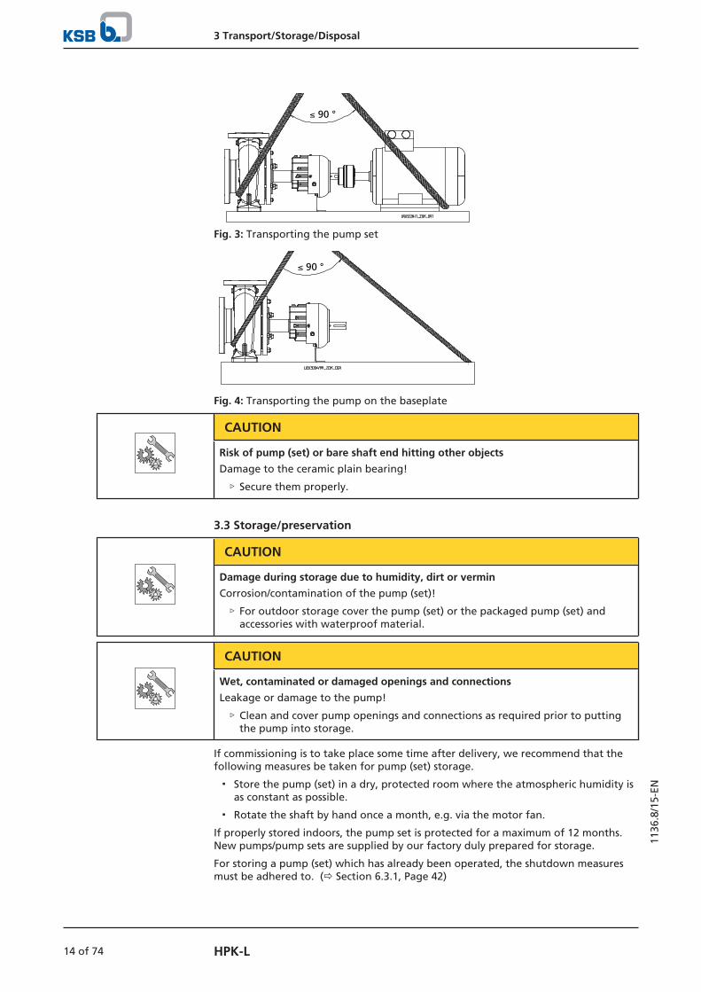
Fig. 3: Transporting the pump set
≤ 90 °
Fig. 4: Transporting the pump on the baseplate
CAUTION
Risk of pump (set) or bare shaft end hitting other objects
Damage to the ceramic plain bearing!
▷ Secure them properly.
3.3 Storage/preservation
CAUTION
Damage during storage due to humidity, dirt or vermin
Corrosion/contamination of the pump (set)!
▷ For outdoor storage cover the pump (set) or the packaged pump (set) andaccessories with waterproof material.
CAUTION
Wet, contaminated or damaged openings and connections
Leakage or damage to the pump!
▷ Clean and cover pump openings and connections as required prior to puttingthe pump into storage.
If commissioning is to take place some time after delivery, we recommend that thefollowing measures be taken for pump (set) storage.
▪ Store the pump (set) in a dry, protected room where the atmospheric humidity isas constant as possible.
▪ Rotate the shaft by hand once a month, e.g. via the motor fan.
If properly stored indoors, the pump set is protected for a maximum of 12 months.New pumps/pump sets are supplied by our factory duly prepared for storage.
For storing a pump (set) which has already been operated, the shutdown measuresmust be adhered to. (ð Section 6.3.1, Page 42)
3 Transport/Storage/Disposal
15 of 74HPK-L
1136
.8/1
5-EN
3.4 Return to supplier1. Drain the pump as per operating instructions. (ð Section 7.3, Page 49)
2. Flush and clean the pump, particularly if it has been used for handling noxious,explosive, hot or other hazardous fluids.
3. If the pump has handled fluids whose residues could lead to corrosion damagein the presence of atmospheric humidity or could ignite upon contact withoxygen also neutralise the pump and blow through with anhydrous inert gas toensure drying.
4. Always complete and enclose a certificate of decontamination when returningthe pump.Indicate any safety measures and decontamination measures taken.(ð Section 11, Page 69)
NOTE
If required, a blank certificate of decontamination can be downloaded from thefollowing web site: www.ksb.com/certificate_of_decontamination
3.5 Disposal
WARNING
Fluids handled, consumables and supplies which are hot and/or pose a healthhazard
Hazard to persons and the environment!
▷ Collect and properly dispose of flushing fluid and any fluid residues.
▷ Wear safety clothing and a protective mask if required.
▷ Observe all legal regulations on the disposal of fluids posing a health hazard.
1. Dismantle the pump (set).Collect greases and other lubricants during dismantling.
2. Separate and sort the pump materials, e.g. by:- Metals- Plastics- Electronic waste- Greases and other lubricants
3. Dispose of materials in accordance with local regulations or in anothercontrolled manner.
4 Description of the Pump (Set)
16 of 74 HPK-L
1136
.8/1
5-EN
4 Description of the Pump (Set)
4.1 General description▪ Heat transfer fluid / hot water pump
Pump for handling hot water and organic or synthetic heat transfer fluids in pipingor tank systems.
Standard design for plants (large heating systems, forced circulation boilers, districtheating systems, etc).
4.2 Product information as per Regulation No. 1907/2006 (REACH)For information as per chemicals Regulation (EC) No. 1907/2006 (REACH), see https://www.ksb.com/ksb-en/About-KSB/Corporate-responsibility/reach/ .
4.3 Designation
Example: HPK- L S 4 80- 200
Table 5: Key to the designation
Code Description
HPK Type series
L Air-cooled
S Material of wetted components
4 Pressure class
80 Nominal discharge nozzle diameter [mm]
200 Nominal impeller diameter [mm]
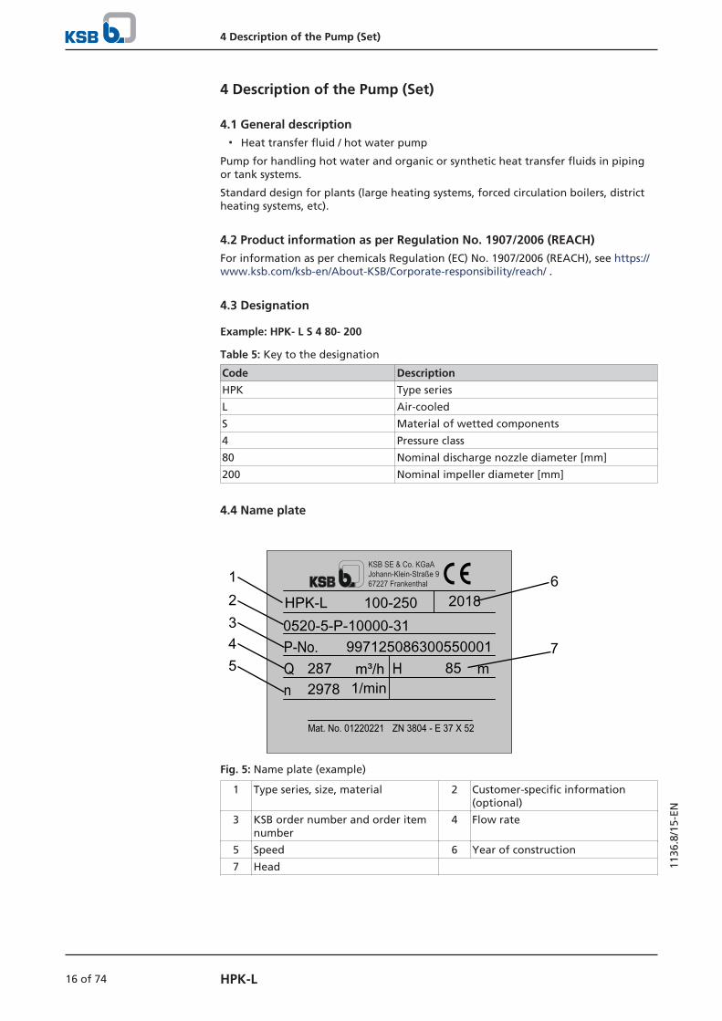
4.4 Name plate
KSB SE & Co. KGaAJohann-Klein-Straße 967227 Frankenthal
ZN 3804 - E 37 X 52
Qn
HP-No.
Mat. No. 01220221
HPK-L 100-250 20180520-5-P-10000-31
997125086300550001287 m³/h2978 1/min
85 m
12
543
6
7
Fig. 5: Name plate (example)
1 Type series, size, material 2 Customer-specific information(optional)
3 KSB order number and order itemnumber
4 Flow rate
5 Speed 6 Year of construction
7 Head

4 Description of the Pump (Set)
17 of 74HPK-L
1136
.8/1
5-EN
4.5 Design details
Design
▪ Volute casing pump
▪ Horizontal installation
▪ Back pull-out design
▪ Single-stage
▪ Technical requirements to ISO 5199
▪ Dimensions and ratings to ISO 2858complemented by pumps of nominal diameters DN 25, DN 200, DN 250 andnominal impeller diameter 500 mm
Pump casing
Fig. 6: Pump feet, bottom
▪ Single or double volute, depending on the pump size
▪ Radially split volute casing
▪ Volute casing (with casing wear ring, if applicable) and casing cover
Impeller type
▪ Closed radial impeller with multiply curved vanes
▪ Back vanes reduce axial thrust.
Shaft seal
▪ Single, balanced standardised mechanical seal
– The seal chamber is located between the product-lubricated pump-end plainbearing and the external, drive-end rolling element bearing.
Mechanical seal in "dead end" arrangement
1. Never use mechanical seals which have not been approved by KSB.
2. Due to the complex conditions which need to be fulfilled for heat transfer fluidpumps, the use of mechanical seals not approved by KSB shall not be covered byKSB's scope of warranty.
Fig. 7: Mechanical seal in "dead end" arrangement
The seal chamber is cooled by cooling fins and ambient cooling air.

4 Description of the Pump (Set)
18 of 74 HPK-L
1136
.8/1
5-EN
There is no external cooling system!
Design specifications Drive-end bearing:
▪ Fixed bearing
▪ Grease-packed angular contact ball bearings sealed for life
▪ Axial movement of the rotor limited to 0.5 mm maximum
▪ Axial seal rings on both sides
Pump-end bearing:
▪ Radial bearing
▪ Absorbs radial loads only
▪ Product-lubricated ceramic bearing
Bearing bracket designation Example: P03
Table 6: Bearing bracket designation
Code Description
L Air-cooled bearing bracket with integrated shaft seal chamber
P Process design
03 Size code (based on the dimensions of seal chamber and shaft end)
Refer to the data sheet to find your bearing design.
Bearings used Table 7: Bearing design
KSB designation FAG designation SKF designation
B.G B-TVP-UA BECBP
B.G 8 B-TVP-UA 80 BEC86P
Table 8: Standard bearings
Bearingbracket
Pump end Drive end
Plain bearing [diameter in mm] Angular contact ball bearings
LP02 SSiC, 37 mm 2 x 7307 B.G
LP03 SSiC, 50 mm 2 x 7307 B.G
LP04 SSiC, 50 mm 2 x 7309 B.G.8
LP05 SSiC, 62 mm 2 x 7313 B.G
LP06 SSiC, 72 mm 2 x 7315 B.G
4 Description of the Pump (Set)
19 of 74HPK-L
1136
.8/1
5-EN
4.6 Configuration and function
1
3
2
6
109
4
8
7
5
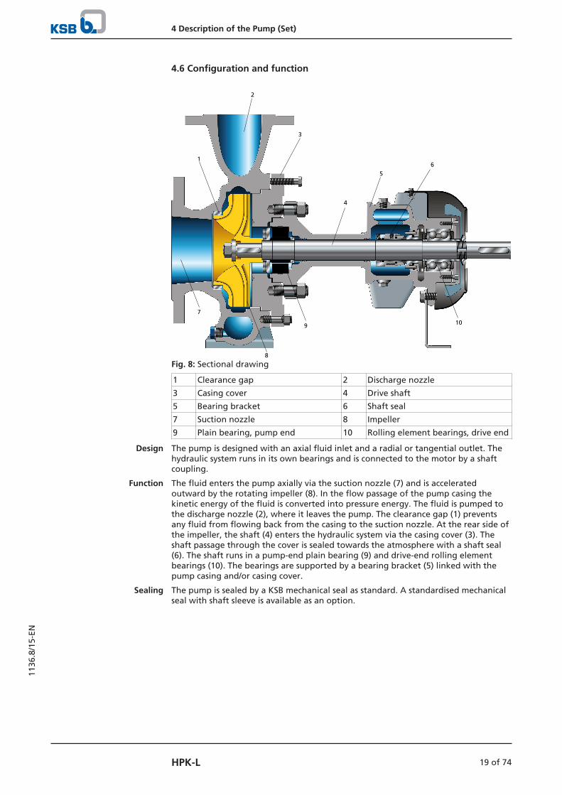
Fig. 8: Sectional drawing
1 Clearance gap 2 Discharge nozzle
3 Casing cover 4 Drive shaft
5 Bearing bracket 6 Shaft seal
7 Suction nozzle 8 Impeller
9 Plain bearing, pump end 10 Rolling element bearings, drive end
Design The pump is designed with an axial fluid inlet and a radial or tangential outlet. Thehydraulic system runs in its own bearings and is connected to the motor by a shaftcoupling.
Function The fluid enters the pump axially via the suction nozzle (7) and is acceleratedoutward by the rotating impeller (8). In the flow passage of the pump casing thekinetic energy of the fluid is converted into pressure energy. The fluid is pumped tothe discharge nozzle (2), where it leaves the pump. The clearance gap (1) preventsany fluid from flowing back from the casing to the suction nozzle. At the rear side ofthe impeller, the shaft (4) enters the hydraulic system via the casing cover (3). Theshaft passage through the cover is sealed towards the atmosphere with a shaft seal(6). The shaft runs in a pump-end plain bearing (9) and drive-end rolling elementbearings (10). The bearings are supported by a bearing bracket (5) linked with thepump casing and/or casing cover.
Sealing The pump is sealed by a KSB mechanical seal as standard. A standardised mechanicalseal with shaft sleeve is available as an option.
4 Description of the Pump (Set)
20 of 74 HPK-L
1136
.8/1
5-EN
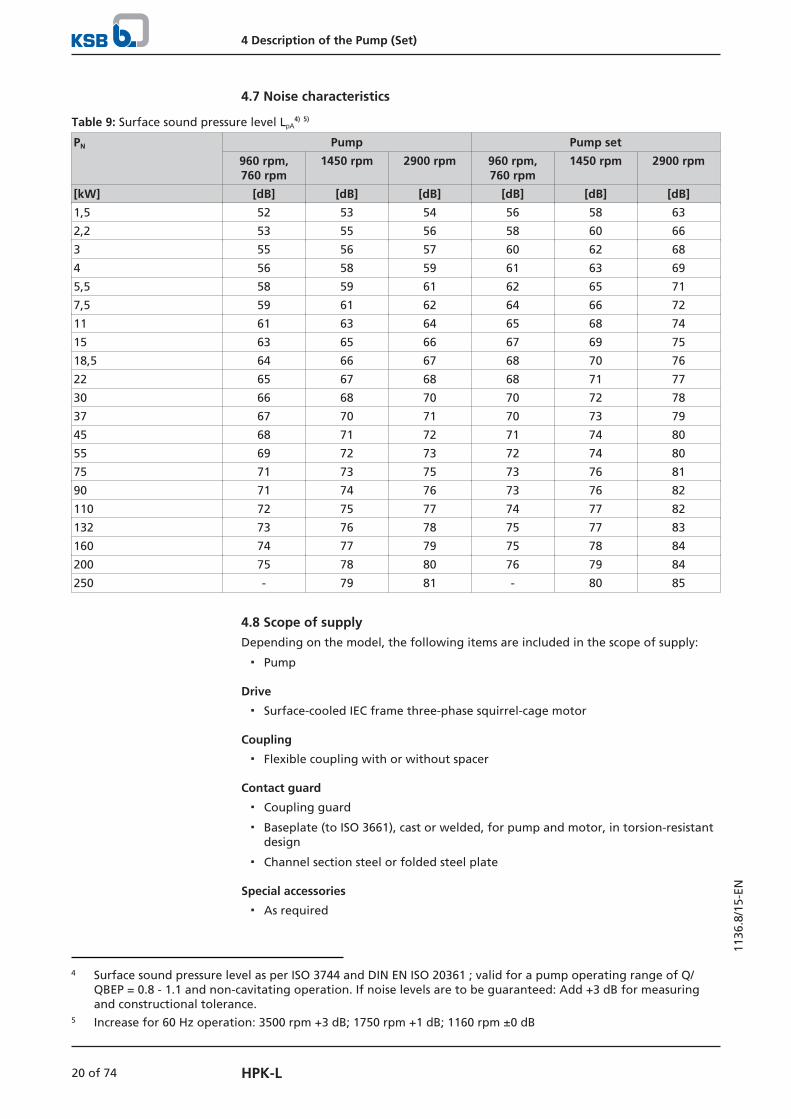
4.7 Noise characteristics
Table 9: Surface sound pressure level LpA4) 5)
PN Pump Pump set
960 rpm,760 rpm
1450 rpm 2900 rpm 960 rpm,760 rpm
1450 rpm 2900 rpm
[kW] [dB] [dB] [dB] [dB] [dB] [dB]
1,5 52 53 54 56 58 63
2,2 53 55 56 58 60 66
3 55 56 57 60 62 68
4 56 58 59 61 63 69
5,5 58 59 61 62 65 71
7,5 59 61 62 64 66 72
11 61 63 64 65 68 74
15 63 65 66 67 69 75
18,5 64 66 67 68 70 76
22 65 67 68 68 71 77
30 66 68 70 70 72 78
37 67 70 71 70 73 79
45 68 71 72 71 74 80
55 69 72 73 72 74 80
75 71 73 75 73 76 81
90 71 74 76 73 76 82
110 72 75 77 74 77 82
132 73 76 78 75 77 83
160 74 77 79 75 78 84
200 75 78 80 76 79 84
250 - 79 81 - 80 85
4.8 Scope of supplyDepending on the model, the following items are included in the scope of supply:
▪ Pump
Drive
▪ Surface-cooled IEC frame three-phase squirrel-cage motor
Coupling
▪ Flexible coupling with or without spacer
Contact guard
▪ Coupling guard
▪ Baseplate (to ISO 3661), cast or welded, for pump and motor, in torsion-resistantdesign
▪ Channel section steel or folded steel plate
Special accessories
▪ As required
4 Surface sound pressure level as per ISO 3744 and DIN EN ISO 20361 ; valid for a pump operating range of Q/QBEP = 0.8 - 1.1 and non-cavitating operation. If noise levels are to be guaranteed: Add +3 dB for measuringand constructional tolerance.
5 Increase for 60 Hz operation: 3500 rpm +3 dB; 1750 rpm +1 dB; 1160 rpm ±0 dB
4 Description of the Pump (Set)
21 of 74HPK-L
1136
.8/1
5-EN
4.9 Dimensions and weightsFor dimensions and weights please refer to the general arrangement drawing/outlinedrawing of the pump/pump set.

5 Installation at Site
22 of 74 HPK-L
1136
.8/1
5-EN
5 Installation at Site
5.1 Checks to be carried out prior to installation
Place of installation
WARNING
Installation on a mounting surface which is unsecured and cannot support the load
Personal injury and damage to property!
▷ Use a concrete of compressive strength class C12/15 which meets therequirements of exposure class XC1 to EN 206-1.
▷ The mounting surface must be set, flat, and level.
▷ Observe the weights indicated.
1. Check the structural requirements.All structural work required must have been prepared in accordance with thedimensions stated in the outline drawing/general arrangement drawing.
5.2 Installing the pump setAlways install the pump set in a horizontal position.
DANGER
Excessive temperatures due to improper installation
Explosion hazard!
▷ Install the pump in a horizontal position to ensure self-venting of the pump.
DANGER
Electrostatic charging due to insufficient potential equalisation
Explosion hazard!
▷ Make sure that the connection between pump and baseplate is electricallyconductive.

5 Installation at Site
23 of 74HPK-L
1136
.8/1
5-EN
5.2.1 Installation on the foundation
L1
32Fig. 9: Fitting the shims
L Bolt-to-bolt distance 1 Shim
2 Shim if (L) > 800 mm 3 Foundation bolt
ü The foundation has the required strength and characteristics.
ü The foundation has been prepared in accordance with the dimensions given inthe outline drawing/general arrangement drawing.
1. Position the pump set on the foundation and level it with the help of a spiritlevel placed on the shaft and discharge nozzle.Permissible deviation: 0.2 mm/m
2. Use shims (1) for height compensation if necessary. Always fit shims, if any, immediately to the left and right of the foundationbolts (3) between the baseplate/foundation frame and the foundation. For a bolt-to-bolt distance (L) > 800 mm fit additional shims (2) halfway betweenthe bolt holes. All shims must lie perfectly flush.
3. Insert the foundation bolts (3) into the holes provided.
4. Use concrete to set the foundation bolts (3) into the foundation.
5. Wait until the concrete has set firmly, then level the baseplate.
6. Tighten the foundation bolts (3) evenly and firmly.
7. Grout the baseplate using low-shrinkage concrete with a standard particle sizeand a water/cement ratio of ≤ 0.5.Produce flowability with the help of a solvent.Perform secondary treatment of the concrete to EN 206.
NOTE
For low-noise operation contact the manufacturer to check whether the pump setcan be installed on anti-vibration mounts.
NOTE
Expansion joints can be fitted between the pump and the suction line or dischargeline.

5 Installation at Site
24 of 74 HPK-L
1136
.8/1
5-EN
5.2.2 Installation without foundation
4
1
2
3
Fig. 10: Adjusting the levelling elements
1, 3 Locknut 2 Adjusting nut
4 Machine mount
ü The installation surface has the required strength and characteristics.
1. Position the pump set on the machine mounts (4) and align it with the help of aspirit level (on the shaft/discharge nozzle).
2. To adjust any differences in height, loosen the locknuts (1, 3) of the machinemounts (4).
3. Turn the adjusting nut (2) until any differences in height have beencompensated.
4. Re-tighten the locknuts (1, 3) at the machine mounts (4).
5.3 Piping
5.3.1 Connecting the piping
DANGER
Impermissible loads acting on the pump nozzles
Danger to life from escaping hot, toxic, corrosive or flammable fluids!
▷ Do not use the pump as an anchorage point for the piping.
▷ Anchor the pipes in close proximity to the pump and connect them properlywithout transmitting any stresses or strains.
▷ Observe the permissible forces and moments at the pump nozzles.
▷ Take appropriate measures to compensate for thermal expansion of the piping.
CAUTION
Incorrect earthing during welding work at the piping
Destruction of rolling element bearings (pitting effect)!
▷ Never earth the electric welding equipment on the pump or baseplate.
▷ Prevent current flowing through the rolling element bearings.

5 Installation at Site
25 of 74HPK-L
1136
.8/1
5-EN
NOTE
Installing check and shut-off elements in the system is recommended, depending onthe type of plant and pump. However, such elements must not obstruct properdrainage or hinder disassembly of the pump.
ü Suction lift lines have been laid with a rising slope, suction head lines with adownward slope towards the pump.
ü A flow stabilisation section having a length equivalent to at least twice thediameter of the suction flange has been provided upstream of the suction flange.
ü The nominal diameters of the pipelines are at least equal to the nominaldiameters of the pump nozzles.
ü Adapters to larger diameters have a diffuser angle of approximately 8° toprevent excessive pressure losses.
ü The pipelines have been anchored in close proximity to the pump and connectedwithout transmitting any stresses or strains.
CAUTION
Welding beads, scale and other impurities in the piping
Damage to the pump!
▷ Remove any impurities from the piping.
▷ If necessary, install a filter.
▷ Observe the information in (ð Section 7.2.2.3, Page 48) .
1. Thoroughly clean, flush and blow through all vessels, pipelines and connections(especially of new installations).
2. Before installing the pump in the piping, remove the flange covers on thesuction and discharge nozzles of the pump.
3. Check that the inside of the pump is free from any foreign objects. Remove anyforeign objects.
4. If required, install a filter in the piping (see figure: Filter in the piping).
1
2Fig. 11: Filter in the piping
1 Differential pressure gauge 2 Filter
NOTE
Use a filter with laid-in wire mesh (mesh width 0.5 mm, wire diameter 0.25 mm) ofcorrosion-resistant material.Use a filter with a filter area three times the cross-section of the piping.Conical filters have proved suitable.
5. Connect the pump nozzles to the piping.

5 Installation at Site
26 of 74 HPK-L
1136
.8/1
5-EN
CAUTION
Aggressive flushing liquid and pickling agent
Damage to the pump!
▷ Match the cleaning operation mode and duration of flushing and pickling tothe casing materials and seal materials used.
5.3.2 Permissible forces and moments at the pump nozzles
[+]Fy
Fz
Fx
Fx
Fz
Fy
Fx
Fz
Fy
My
Mz
Mx
Forces and moments at the pump nozzles
The permissible resultant forces havebeen determined according to:
The data on forces and moments apply to static piping loads only. If the limits areexceeded, they must be checked and verified.If a computerised strength analysis is required, values are available on request only. The values are only applicable if the pump is installed on a completely groutedbaseplate and bolted to a rigid and level foundation.
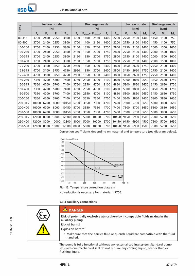
Table 10: Forces and moments at the pump nozzles
Size
s Suction nozzle Discharge nozzle Suction nozzle Discharge nozzle
[N] [N] [Nm] [Nm]
Fx Fy Fz Fres Fx FyTens+ FyCompr- Fz Fres Mx My Mz Mx My Mz
25-160 1050 700 850 1100 500 350 650 450 700 550 450 300 400 300 200
25-200 1050 700 850 1100 500 350 650 450 700 550 450 300 400 300 200
32-125 1350 900 1100 1400 700 450 850 550 900 700 550 350 450 350 250
32-160 1350 900 1100 1400 700 450 850 550 900 700 550 350 450 350 250
32-200 1350 900 1100 1400 700 450 850 550 900 700 550 350 450 350 250
32-250 1350 900 1100 1400 700 450 850 550 900 700 550 350 450 350 250
40-160 1750 1150 1400 1800 850 550 1100 700 1100 1150 850 600 550 450 300
40-200 1750 1150 1400 1800 850 550 1100 700 1100 1150 850 600 550 450 300
40-250 1750 1150 1400 1800 850 550 1100 700 1100 1150 850 600 550 450 300
40-315 1750 1150 1400 1800 850 550 1100 700 1100 1150 850 600 550 450 300
50-160 2150 1400 1700 2200 1100 700 1350 900 1400 1450 1100 750 700 550 350
50-200 2150 1400 1700 2200 1100 700 1350 900 1400 1450 1100 750 700 550 350
50-250 2150 1400 1700 2200 1100 700 1350 900 1400 1450 1100 750 700 550 350
50-315 2150 1400 1700 2200 1100 700 1350 900 1400 1450 1100 750 700 550 350
65-160 2700 1750 2150 2750 1400 900 1750 1150 1800 2000 1500 1000 1150 850 600
65-200 2700 1750 2150 2750 1400 900 1750 1150 1800 2000 1500 1000 1150 850 600
65-250 2700 1750 2150 2750 1400 900 1750 1150 1800 2000 1500 1000 1150 850 600
65-315 2700 1750 2150 2750 1400 900 1750 1150 1800 2000 1500 1000 1150 850 600
80-160 3700 2400 2950 3800 1700 1100 2150 1400 2200 2750 2100 1400 1450 1100 750
80-200 3700 2400 2950 3800 1700 1100 2150 1400 2200 2750 2100 1400 1450 1100 750
80-250 3700 2400 2950 3800 1700 1100 2150 1400 2200 2750 2100 1400 1450 1100 750
5 Installation at Site
27 of 74HPK-L
1136
.8/1
5-EN
Size
s Suction nozzle Discharge nozzle Suction nozzle Discharge nozzle
[N] [N] [Nm] [Nm]
Fx Fy Fz Fres Fx FyTens+ FyCompr- Fz Fres Mx My Mz Mx My Mz
80-315 3700 2400 2950 3800 1700 1100 2150 1400 2200 2750 2100 1400 1450 1100 750
80-400 3700 2400 2950 3800 1700 1100 2150 1400 2200 2750 2100 1400 1450 1100 750
100-200 3700 2400 2950 3800 2150 1350 2700 1750 2800 2750 2100 1400 2000 1500 1000
100-250 3700 2400 2950 3800 2150 1350 2700 1750 2800 2750 2100 1400 2000 1500 1000
100-315 3700 2400 2950 3800 2150 1350 2700 1750 2800 2750 2100 1400 2000 1500 1000
100-400 3700 2400 2950 3800 2150 1350 2700 1750 2800 2750 2100 1400 2000 1500 1000
125-250 4700 3100 3750 4750 2950 1850 3700 2400 3800 3450 2650 1750 2750 2100 1400
125-315 4700 3100 3750 4750 2950 1850 3700 2400 3800 3450 2650 1750 2750 2100 1400
125-400 4700 3100 3750 4750 2950 1850 3700 2400 3800 3450 2650 1750 2750 2100 1400
150-250 7350 4700 5700 7400 3750 2350 4700 3100 4850 5300 3850 2650 3450 2650 1750
150-315 7350 4700 5700 7400 3750 2350 4700 3100 4850 5300 3850 2650 3450 2650 1750
150-400 7350 4700 5700 7400 3750 2350 4700 3100 4850 5300 3850 2650 3450 2650 1750
150-500 7350 4700 5700 7400 3750 2350 4700 3100 4850 5300 3850 2650 3450 2650 1750
200-250 7350 4700 5700 7400 5700 3550 7350 4700 7400 5300 3850 2650 5300 3850 2650
200-315 10000 6700 8000 10450 5700 3550 7350 4700 7400 7500 5700 3650 5300 3850 2650
200-400 10000 6700 8000 10450 5700 3550 7350 4700 7400 7500 5700 3650 5300 3850 2650
200-500 10000 6700 8000 10450 5700 3550 7350 4700 7400 7500 5700 3650 5300 3850 2650
250-315 12000 8000 10000 12800 8000 5000 10000 6700 10450 9150 6900 4500 7500 5700 3650
250-400 12000 8000 10000 12800 8000 5000 10000 6700 10450 9150 6900 4500 7500 5700 3650
250-500 12000 8000 10000 12800 8000 5000 10000 6700 10450 9150 6900 4500 7500 5700 3650
Correction coefficients depending on material and temperature (see diagram below).
1,00
0,75
0,80
0,85
0,90
0,95
0,50
0,55
0,60
0,65
0,70
400350300250200150120
JL1040
GP240GH+NJS1025
1.4408
°C
Correction coefficient
Fig. 12: Temperature correction diagram
No reduction is necessary for material 1.7706.
5.3.3 Auxiliary connections
DANGER
Risk of potentially explosive atmosphere by incompatible fluids mixing in theauxiliary piping
Risk of burns!
Explosion hazard!
▷ Make sure that the barrier fluid or quench liquid are compatible with the fluidhandled.
The pump is fully functional without any external cooling system. Standard pumpsets with one mechanical seal do not require any cooling liquid, barrier fluid orflushing liquid.

5 Installation at Site
28 of 74 HPK-L
1136
.8/1
5-EN
Fig. 13: Quench connections
24A Quench outlet 24E Quench inlet
For pump sets with two mechanical seals in tandem arrangement, connect anunpressurised quench liquid supply to the "Quench outlet" (24E) and "Quenchinlet" (24A) connections.
5.4 Enclosure/insulation
DANGER
An explosive atmosphere forms due to insufficient venting
Explosion hazard!
▷ Never close or cover the perforation of the bearing bracket guards (e.g. byinsulation).
WARNING
The volute casing and casing/discharge cover take on the same temperature as thefluid handled
Risk of burns!
▷ Insulate the volute casing.
▷ Fit protective equipment.
CAUTION
Heat build-up in the bearing bracket
Damage to the bearing!
▷ Never insulate the bearing bracket, bearing bracket lantern and casing cover.
5.5 Checking the coupling alignment
DANGER
Inadmissible temperatures at the coupling or bearings due to misalignment of thecoupling
Explosion hazard!
Risk of burns!
▷ Make sure that the coupling is correctly aligned at all times.
5 Installation at Site
29 of 74HPK-L
1136
.8/1
5-EN
CAUTION
Misalignment of pump and motor shafts
Damage to pump, motor and coupling!
▷ Always check the coupling after the pump has been installed and connected tothe piping.
▷ Also check the coupling of pump sets supplied with pump and motor mountedon the same baseplate.
BA
A B
1
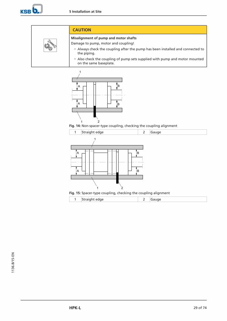
1 2Fig. 14: Non-spacer-type coupling, checking the coupling alignment
1 Straight edge 2 Gauge
B
B
A
A
21
1
Fig. 15: Spacer-type coupling, checking the coupling alignment
1 Straight edge 2 Gauge

5 Installation at Site
30 of 74 HPK-L
1136
.8/1
5-EN
BA
A B
1
1
2 2
12
2Fig. 16: Double Cardan spacer-type coupling, checking the coupling alignment
1 Straight edge 2 Gauge
Table 11: Permissible alignment offset of coupling halves
Coupling type Radial offset Axial offset
[mm] [mm]
Non-spacer-type coupling (ð Fig. 14) ≤ 0,1 ≤ 0,1
Spacer-type coupling (ð Fig. 15) ≤ 0,1 ≤ 0,1
Double Cardan coupling (ð Fig. 16) ≤ 0,5 ≤ 0,5
ü The coupling guard and its footboard, if any, have been removed.
1. Loosen the support foot and re-tighten it without transmitting any stresses andstrains.
2. Place the straight edge axially on both coupling halves.
3. Leave the straight edge in this position and turn the coupling by hand. The coupling is aligned correctly if the distances A and B to the respective shaftsare the same at all points around the circumference.Observe the permissible radial offset in coupling half alignment (ð Table 11) both during standstill and at operating temperature as well as under inletpressure.
4. Check the distance (dimension see general arrangement drawing) between thetwo coupling halves around the circumference. The coupling is correctly aligned if the distance between the two couplinghalves is the same at all points around the circumference.Observe the permissible axial offset in coupling half alignment (ð Table 11) both during standstill and at operating temperature as well as under inletpressure.
5. If alignment is correct, re-install the coupling guard and its footboard, if any.
Checking the coupling alignment with a laser tool
Coupling alignment may also be checked with a laser tool. Observe thedocumentation provided by the manufacturer of the measuring instrument.
5.6 Aligning the pump and motorAfter having installed the pump set and connected the piping, check the couplingalignment and, if required, re-align the pump set (at the motor).

5 Installation at Site
31 of 74HPK-L
1136
.8/1
5-EN
5.6.1 Motors with adjusting screw
1
3
2
Fig. 17: Motor with adjusting screw
1 Hexagon head bolt 2 Adjusting screw
3 Locknut
ü The coupling guard and its footboard, if any, have been removed.
1. Check the coupling alignment.
2. Unscrew the hexagon head bolts (1) at the motor and the locknuts (3) at thebaseplate.
3. Turn the adjusting screws (2) by hand or by means of an open-end wrench untilthe coupling alignment is correct and all motor feet rest squarely on thebaseplate.
4. Re-tighten the hexagon head bolts (1) at the motor and the locknuts (3) at thebaseplate.
5. Check proper functioning of coupling/shaft. Check that coupling/shaft can easily be rotated by hand.
WARNING
Unprotected rotating coupling
Risk of injury by rotating shafts!
▷ Always operate the pump set with a coupling guard.If the customer specifically requests not to include a coupling guard in KSB'sdelivery, then the operator must supply one!
▷ Observe all relevant regulations for selecting a coupling guard.
DANGER
Risk of ignition by frictional sparks
Explosion hazard!!
▷ Choose a coupling guard material that is non-sparking in the event ofmechanical contact.
6. Fit the coupling guard and its footboard, if any.
7. Check the distance between coupling and coupling guard.The coupling guard must not touch the coupling.
5.6.2 Motors without adjusting screw
Any differences in the centreline heights of the pump and motor shafts arecompensated by means of shims.

5 Installation at Site
32 of 74 HPK-L
1136
.8/1
5-EN
1Fig. 18: Pump set with shim
1 Shim
ü The coupling guard and its footboard, if any, have been removed.
1. Check the coupling alignment.
2. Loosen the hexagon head bolts at the motor.
3. Insert shims underneath the motor feet until the difference in shaft centrelineheight has been compensated.
4. Re-tighten the hexagon head bolts.
5. Check proper functioning of coupling/shaft. Check that coupling/shaft can easily be rotated by hand.
WARNING
Unprotected rotating coupling
Risk of injury by rotating shafts!
▷ Always operate the pump set with a coupling guard.If the customer specifically requests not to include a coupling guard in KSB'sdelivery, then the operator must supply one!
▷ Observe all relevant regulations for selecting a coupling guard.
DANGER
Risk of ignition by frictional sparks
Explosion hazard!!
▷ Choose a coupling guard material that is non-sparking in the event ofmechanical contact.
6. Fit the coupling guard and its footboard, if any.
7. Check the distance between coupling and coupling guard.The coupling guard must not touch the coupling.
5.7 Electrical connection
DANGER
Electrical connection work by unqualified personnel
Risk of fatal injury due to electric shock!
▷ Always have the electrical connections installed by a trained and qualifiedelectrician.
▷ Observe regulations IEC 60364 and, for explosion-proof models, EN 60079.

5 Installation at Site
33 of 74HPK-L
1136
.8/1
5-EN
WARNING
Incorrect connection to the mains
Damage to the power supply network, short circuit!
▷ Observe the technical specifications of the local energy supply companies.
1. Check the available mains voltage against the data on the motor name plate.
2. Select an appropriate starting method.
NOTE
Installing a motor protection device is recommended.
5.7.1 Setting the time relay
CAUTION
Switchover between star and delta on three-phase motors with star-delta startingtakes too long.
Damage to the pump (set)!
▷ Keep switch-over intervals between star and delta as short as possible.
Table 12: Time relay settings for star-delta starting:
Motor rating Y time to be set
[kW] [s]
≤ 30 < 3
> 30 < 5
5.7.2 Earthing
DANGER
Electrostatic charging
Explosion hazard!
Damage to the pump set!
▷ Connect the PE conductor to the earthing terminal provided.
▷ Provide for potential equalisation between the pump set and the foundation.
5.7.3 Connecting the motor
NOTE
In compliance with IEC 60034-8, three-phase motors are always wired for clockwiserotation (looking at the motor shaft stub).
The pump's direction of rotation is indicated by an arrow on the pump.
1. Match the motor's direction of rotation to that of the pump.
2. Observe the manufacturer's product literature supplied with the motor.

5 Installation at Site
34 of 74 HPK-L
1136
.8/1
5-EN
5.8 Checking the direction of rotation
DANGER
Temperature increase resulting from contact between rotating and stationarycomponents
Explosion hazard!
Damage to the pump set!
▷ Never check the direction of rotation by starting up the unfilled pump set.
▷ Separate the pump from the motor to check the direction of rotation.
WARNING
Hands inside the pump casing
Risk of injuries, damage to the pump!
▷ Always disconnect the pump set from the power supply and secure it againstunintentional start-up before inserting your hands or other objects into thepump.
CAUTION
Incorrect direction of rotation with non-reversible mechanical seal
Damage to the mechanical seal and leakage!
▷ Separate the pump from the motor to check the direction of rotation.
CAUTION
Drive and pump running in the wrong direction of rotation
Damage to the pump!
▷ Refer to the arrow indicating the direction of rotation on the pump.
▷ Check the direction of rotation. If required, check the electrical connection andcorrect the direction of rotation.
The correct direction of rotation of the motor and pump is clockwise (seen from thedrive end).
1. Start the motor and stop it again immediately to determine the motor'sdirection of rotation.
2. Check the direction of rotation. The motor's direction of rotation must match the arrow indicating the directionof rotation on the pump.
3. If the motor is running in the wrong direction of rotation, check the electricalconnection of the motor and switchgear, if any.

6 Commissioning/Start-up/Shutdown
35 of 74HPK-L
1136
.8/1
5-EN
6 Commissioning/Start-up/Shutdown
6.1 Commissioning/Start-up
6.1.1 Prerequisites for commissioning/start-up
Before commissioning/starting up the pump set, make sure that the followingconditions are met:
▪ The pump set has been properly connected to the power supply and is equippedwith all protection devices. (ð Section 5.7, Page 32)
▪ The pump, including the bearing bracket (mechanical seal chamber), has beenprimed with the fluid to be handled.
▪ The direction of rotation has been checked. (ð Section 5.8, Page 34)
▪ The lubricants have been checked. (ð Section 6.1.2, Page 35)
▪ After prolonged shutdown of the pump (set), the activities required for returningthe equipment to service have been carried out. (ð Section 6.4, Page 43)
NOTE
Hot water shall comply with the requirements of the VdTÜV technical instructionleaflet TCH 1466/AGFW 5-15 (edition 2.89) as a minimum. Do not exceed the following limits:
Table 13: Limits for hot water
Limits
Electrical conductivity < 250 µs/cm
pH at 25 °C 9-10,5
Silicates (SiO2) < 10 mg/l
Solids < 5 mg/l
NOTE
No warranty can be given for the service life of mechanical seals if hot water withan electrical conductivity exceeding 250 µs/cm or hot water of unknown waterquality is handled.
For ultra-pure water (fully desalinated, demineralised water) with an electricalconductivity < 2 µs/cm, the temperature at the seal faces must be at least 20 % belowthe boiling point.
NOTE
When conditioners producing a greasy film on the mechanical seal faces are used,e.g. Maxigard, Antifrogen N, Preventol Cl-2, KeboX, Nalfleet 9-11, no warranty canbe given on the seal life because of their adverse effect on the seal. In such casesplease contact KSB.
6.1.2 Filling in lubricants
Grease-lubricated bearings have been packed with grease at the factory.
6.1.3 Shaft seal
Observe the instructions on dismantling (ð Section 7.4.7, Page 51) or assembly (ð Section 7.5, Page 53) .
When new plants are commissioned, large amounts of foreign matter in the systemand a short service life of mechanical seals are to be expected during the initial phaseof operation.

6 Commissioning/Start-up/Shutdown
36 of 74 HPK-L
1136
.8/1
5-EN
NOTE
Only modify the specified sealing concepts and seal types after consultation withKSB. Due to the complex conditions in hot water systems, the use of mechanicalseals not approved by KSB shall not be covered by KSB's scope of warranty.
Quench reservoir If applicable, fill the quench reservoir in accordance with the general arrangementdrawing.
Double mechanical seal Prior to starting up the pump, apply barrier pressure as specified in the generalarrangement drawing.
6.1.4 Quench liquid supply
Permissible quench liquids The quench liquid must be compatible with and suitable for mixing with the fluidhandled.
For synthetic heat transfer oils, a mineral oil based thermal fluid or another mineraloil must be used as a quench liquid.Heat transfer oils of the diphyl group are not suitable for use as quench liquids.
6.1.5 Priming and venting the pump
DANGER
Risk of potentially explosive atmosphere inside the pump
Explosion hazard!
▷ The pump internals in contact with the fluid to be handled, including the sealchamber and auxiliary systems, must be filled with the fluid to be handled at alltimes.
▷ Provide sufficient inlet pressure.
▷ Provide an appropriate monitoring system.
DANGER
Shaft seal failure caused by insufficient lubrication
Hot or toxic fluid could escape!
Damage to the pump!
▷ Before starting up the pump set, vent the pump and suction line and primeboth with the fluid to be handled.
DANGER
Hot fluid spurting out of the vent chamber
Burns, scalding!
▷ Always use utmost caution during the venting process and wear appropriateprotective gear.
1. Vent the pump and suction line and prime both with the fluid to be handled.
2. Fully open the shut-off element in the suction line.
Venting the seal chamber In as-supplied condition, auxiliary connection 13 D for venting the seal chamber isclosed with screw plug 903.85.
High-temperature pumps must be vented before they are commissioned.
For venting undo screw plug 903.85 by half a turn to one turn maximum. Leave itopen until the gas has left the mechanical seal chamber and fluid starts to escape.Then, tighten the screw plug again.

6 Commissioning/Start-up/Shutdown
37 of 74HPK-L
1136
.8/1
5-EN
13 D
Fig. 19: Auxiliary connection 13 D
13 D Screw plug 903.85
NOTE
We recommend replacing the screw plug with a globe valve and drain line, so thatgases and hot fluids pumped can be drained safely during the venting process.
Venting during pumpoperation
1. Switch off the pump and let it run down to a standstill.
2. This allows the gases to escape reliably.
3. Close the shut-off elements as required by the system configuration.
4. To vent the bearing bracket undo screw plug 903.85 in steps of approx. 1/2 turneach until no more gas escapes.
Excessive venting Excessive venting shall be avoided, as hot product from the piping system will flowthrough the volute casing into the mechanical seal chamber and result in aninadmissible heat build-up in the mechanical seal. Close the vent plug as soon as nomore gas escapes.
6.1.6 Final check
1. Remove the coupling guard and its footboard, if any.
2. Check the coupling alignment; re-align the coupling, if required.(ð Section 5.5, Page 28)
3. Check proper functioning of coupling/shaft.Check that coupling/shaft can be easily rotated by hand.
4. Fit the coupling guard and its footboard, if any.
5. Check the distance between coupling and coupling guard.The coupling guard must not touch the coupling.
6.1.7 Cooling of the mechanical seal chamber
The mechanical seal chamber is integrated in the bearing bracket and cooled by theambient temperature via cooling fins.
An integrated fan impeller ensures a continuous cooling air flow.
An unobstructed supply of cooling air to the fan hood and fan impeller must beensured at all times!
1. In exceptional cases, the pump can be operated without the integrated fanimpeller. If the coarse dust blocks the cooling air intake, the following parts also have tobe removed:
▪ Fan hood 832
▪ Guard 680
Cooling air flow with a cooling air velocity of at least 4 m/s must be provided in theproximity of the cooling fins.The cooling air flow is generated by the motor cooling device or an external fan.
6 Commissioning/Start-up/Shutdown
38 of 74 HPK-L
1136
.8/1
5-EN
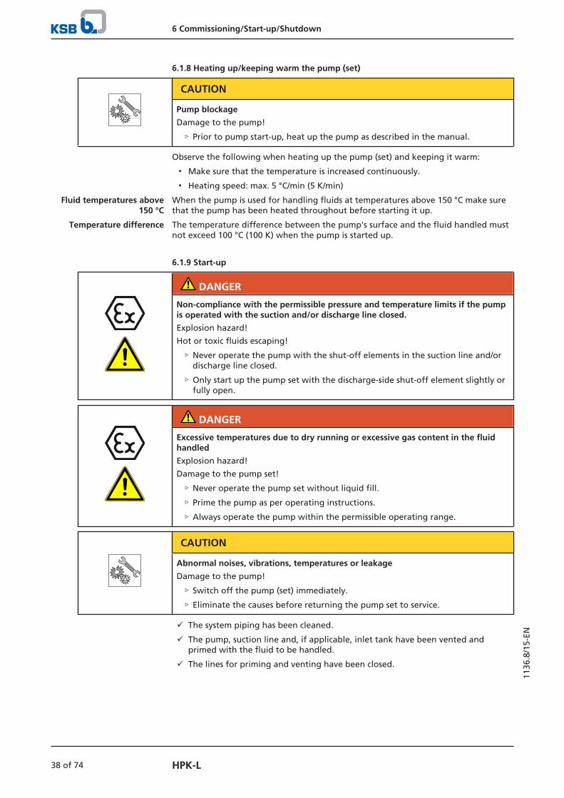
6.1.8 Heating up/keeping warm the pump (set)
CAUTION
Pump blockage
Damage to the pump!
▷ Prior to pump start-up, heat up the pump as described in the manual.
Observe the following when heating up the pump (set) and keeping it warm:
▪ Make sure that the temperature is increased continuously.
▪ Heating speed: max. 5 °C/min (5 K/min)
Fluid temperatures above150 °C
When the pump is used for handling fluids at temperatures above 150 °C make surethat the pump has been heated throughout before starting it up.
Temperature difference The temperature difference between the pump's surface and the fluid handled mustnot exceed 100 °C (100 K) when the pump is started up.
6.1.9 Start-up
DANGER
Non-compliance with the permissible pressure and temperature limits if the pumpis operated with the suction and/or discharge line closed.
Explosion hazard!
Hot or toxic fluids escaping!
▷ Never operate the pump with the shut-off elements in the suction line and/ordischarge line closed.
▷ Only start up the pump set with the discharge-side shut-off element slightly orfully open.
DANGER
Excessive temperatures due to dry running or excessive gas content in the fluidhandled
Explosion hazard!
Damage to the pump set!
▷ Never operate the pump set without liquid fill.
▷ Prime the pump as per operating instructions.
▷ Always operate the pump within the permissible operating range.
CAUTION
Abnormal noises, vibrations, temperatures or leakage
Damage to the pump!
▷ Switch off the pump (set) immediately.
▷ Eliminate the causes before returning the pump set to service.
ü The system piping has been cleaned.
ü The pump, suction line and, if applicable, inlet tank have been vented andprimed with the fluid to be handled.
ü The lines for priming and venting have been closed.

6 Commissioning/Start-up/Shutdown
39 of 74HPK-L
1136
.8/1
5-EN
CAUTION
Start-up against open discharge line
Motor overload!
▷ Make sure the motor has sufficient power reserves.
▷ Use a soft starter.
▷ Use speed control.
1. Fully open the shut-off element in the suction head/suction lift line.
2. Close or slightly open the shut-off element in the discharge line.
3. Start up the motor.
4. Immediately after the pump has reached full rotational speed, slowly open theshut-off element in the discharge line and adjust it to comply with the dutypoint.
CAUTION
Misalignment of pump and coupling
Damage to pump, motor and coupling!
▷ When the operating temperature has been reached, switch off the pump setand check the coupling alignment.
5. Check the coupling alignment and re-align the coupling, if required.
6.1.10 Checking the shaft seal
Mechanical seal The mechanical seal only leaks slightly or invisibly (as vapour) during operation.Mechanical seals are maintenance-free.
Slight leakage at the seal is permissible and desirable.
A continuously increasing, heavily dripping leakage at the seal indicates that the sealis defective and must be replaced.
6.1.11 Shutdown
ü The shut-off element in the suction line is and remains open.
1. Close the shut-off element in the discharge line.
2. Switch off the motor and make sure the pump set runs down smoothly to astandstill.
NOTE
If the discharge line is equipped with a non-return or check valve, the shut-offelement may remain open provided that the system conditions and systemregulations are considered and observed.
NOTE
If shut-off is not possible, the pump will run in reverse direction.The reverse runaway speed must be lower than the rated speed.
For prolonged shutdown periods:
1. Close the shut-off element in the suction line.
2. Close the auxiliary connections. If the fluid to be pumped is fed in under vacuum, also supply the shaft seal withbarrier fluid during standstill.Only turn off the cooling liquid supply after the pump has cooled down.

6 Commissioning/Start-up/Shutdown
40 of 74 HPK-L
1136
.8/1
5-EN
CAUTION
Risk of freezing during prolonged pump shutdown periods
Damage to the pump!
▷ Drain the pump and the cooling/heating chambers (if any) or otherwise protectthem against freezing.
6.2 Operating limits
DANGER
Non-compliance with operating limits for pressure, temperature, fluid handled andspeed
Explosion hazard!
Hot or toxic fluid could escape!
▷ Comply with the operating data specified in the data sheet.
▷ Never use the pump for handling fluids it is not designed for.
▷ Avoid prolonged operation against a closed shut-off element.
▷ Never operate the pump at temperatures, pressures or rotational speedsexceeding those specified in the data sheet or on the name plate unless thewritten consent of the manufacturer has been obtained.
DANGER
Formation of a potentially explosive atmosphere inside the pump
Explosion hazard!
▷ When draining tanks take suitable measures to prevent dry running of thepump (e.g. fill level monitoring).
6.2.1 Ambient temperature
CAUTION
Operation outside the permissible ambient temperature
Damage to the pump (set)!
▷ Observe the specified limits for permissible ambient temperatures.
Observe the following parameters and values during operation:
Table 14: Permissible ambient temperatures
Permissible ambient temperature Value
Maximum 40 °C
Minimum See data sheet.
6.2.2 Minimum permissible speed
CAUTION
Plain bearing is overloaded
Damage to the bearings!
▷ Never use a speed of less than 800 rpm.

6 Commissioning/Start-up/Shutdown
41 of 74HPK-L
1136
.8/1
5-EN
6.2.3 Frequency of starts
DANGER
Excessive surface temperature of the motor
Explosion hazard!
Damage to the motor!
▷ In case of explosion-proof motors, observe the frequency of starts specified inthe manufacturer's product literature.
The frequency of starts is determined by the maximum temperature increase of themotor. The frequency of starts depends on the power reserves of the motor insteady-state operation and on the starting conditions (DOL starting, star-deltastarting, moments of inertia, etc). If the start-ups are evenly spaced over the periodindicated, the following limits serve as orientation for start-up with the discharge-side shut-off valve slightly open:
Table 15: Frequency of starts
Motor rating Maximum frequency of starts
[kW] [Starts/hour]
≤ 12 15
≤ 100 10
> 100 5
CAUTION
Re-starting while motor is still running down
Damage to the pump (set)!
▷ Do not re-start the pump set before the pump rotor has come to a standstill.
6.2.4 Fluid handled
6.2.4.1 Flow rate
Unless specified otherwise in the characteristic curves or in the data sheets, thefollowing applies:
▪ Short-time operation: Qmin6) = 0.1 × QBEP
7)
▪ Continuous operation: Qmin6) = 0.3 × QBEP
7)
▪ 2-pole operation: Qmax8) = 1.1 × QBEP
7)
▪ 4-pole operation: Qmax8) = 1.25 × QBEP
7)
The data refer to water and water-like fluids. Longer operating periods with thesefluids and at the flow rates indicated will not cause an additional increase in thetemperatures on the pump surface. However, if the physical properties of the fluidshandled differ from those of water, the calculation formula below must be used tocheck if an additional heat build-up may lead to a dangerous temperature increase atthe pump surface. If necessary, the minimum flow must be increased.
××
×
6 Minimum flow rate7 Flow rate at best efficiency point8 Maximum flow rate

6 Commissioning/Start-up/Shutdown
42 of 74 HPK-L
1136
.8/1
5-EN
Table 16: Key
Symbol Description Unit
c Specific heat capacity J/kg K
g Acceleration due to gravity m/s²
H Pump discharge head m
Tf Fluid temperature °C
TO Temperature at the casing surface °C
Pump efficiency at duty point -
Temperature difference K
6.2.4.2 Density of the fluid handled
The power input of the pump set will change in proportion to the density of the fluidhandled.
CAUTION
Impermissibly high density of the fluid handled
Motor overload!
▷ Observe the information about fluid density in the data sheet.
▷ Make sure the motor has sufficient power reserves.
6.2.4.3 Abrasive fluids
Do not exceed the maximum permissible solids content specified in the data sheet.When the pump handles fluids containing abrasive substances, increased wear of thehydraulic system and shaft seal are to be expected. In this case, reduce the commonlyrecommended inspection intervals.
6.3 Shutdown/storage/preservation
6.3.1 Measures to be taken for shutdown
The pump (set) remains installed
ü Sufficient fluid is supplied for the functional check run of the pump.
1. For prolonged shutdown periods, start up the pump (set) regularly betweenonce a month and once every three months for approximately five minutes.
ð This will prevent the formation of deposits within the pump and the pumpintake area.
The pump (set) is removed from the piping and stored
ü The pump has been properly drained. (ð Section 7.3, Page 49)
ü The safety instructions for dismantling the pump have been observed. (ð Section 7.4.1, Page 49)
ü The permissible ambient temperature for storing the pump is observed.
1. Spray-coat the inside wall of the pump casing and, in particular, the impellerclearance areas with a preservative.
2. Spray the preservative through the suction nozzle and discharge nozzle.It is advisable to then close the pump nozzles (e.g. with plastic caps).
3. Oil or grease all exposed machined parts and surfaces of the pump (withsilicone-free oil and grease, food-approved if required) to protect them againstcorrosion.Observe the additional instructions on preservation. (ð Section 3.3, Page 14)
If the pump set is to be stored temporarily, only preserve the wetted componentsmade of low-alloy materials. Commercially available preservatives can be used forthis purpose. Observe the manufacturer's instructions for application/removal.

6 Commissioning/Start-up/Shutdown
43 of 74HPK-L
1136
.8/1
5-EN
6.4 Returning to serviceFor returning the equipment to service observe the sections on commissioning/start-up and the operating limits. (ð Section 6.1, Page 35) (ð Section 6.2, Page 40)
In addition, carry out all servicing/maintenance operations before returning thepump (set) to service. (ð Section 7, Page 44)
WARNING
Failure to re-install or re-activate protective devices
Risk of injury from moving parts or escaping fluid!
▷ As soon as the work is completed, properly re-install and re-activate any safety-relevant devices and protective devices.
NOTE
If the equipment has been out of service for more than one year, replace allelastomer seals.

7 Servicing/Maintenance
44 of 74 HPK-L
1136
.8/1
5-EN
7 Servicing/Maintenance
7.1 Safety regulations
DANGER
Improper cleaning of coated pump surfaces
Explosion hazard by electrostatic discharge!
▷ When cleaning coated pump surfaces in atmospheres of Explosion group IIC,use suitable anti-static equipment.
DANGER
Sparks produced during servicing work
Explosion hazard!
▷ Observe the safety regulations in force at the place of installation!
▷ Always perform maintenance work at an explosion-proof pump (set) outside ofpotentially explosive atmospheres.
DANGER
Improperly serviced pump set
Explosion hazard!
Damage to the pump set!
▷ Service the pump set regularly.
▷ Prepare a maintenance schedule with special emphasis on lubricants, shaft sealand coupling.
The operator ensures that maintenance, inspection and installation are performed byauthorised, qualified specialist personnel who are thoroughly familiar with themanual.
WARNING
Unintentional starting of the pump set
Risk of injury by moving components and shock currents!
▷ Ensure that the pump set cannot be started unintentionally.
▷ Always make sure the electrical connections are disconnected before carryingout work on the pump set.
WARNING
Fluids handled, consumables and supplies which are hot and/or pose a healthhazard
Risk of injury!
▷ Observe all relevant laws.
▷ When draining the fluid take appropriate measures to protect persons and theenvironment.
▷ Decontaminate pumps which handle fluids posing a health hazard.

7 Servicing/Maintenance
45 of 74HPK-L
1136
.8/1
5-EN
WARNING
Insufficient stability
Risk of crushing hands and feet!
▷ During assembly/dismantling, secure the pump (set)/pump parts to preventtilting or tipping over.
A regular maintenance schedule will help avoid expensive repairs and contribute totrouble-free, reliable operation of the pump, pump set and pump parts with aminimum of servicing/maintenance expenditure and work.
NOTE
All maintenance work, service work and installation work can be carried out by KSBService or authorised workshops. For contact details please refer to the enclosed"Addresses" booklet or visit "www.ksb.com/contact" on the Internet.
Never use force when dismantling and reassembling the pump set.
7.2 Servicing/Inspection
7.2.1 Supervision of operation
DANGER
Incorrectly serviced shaft seal
Explosion hazard!
Hot, toxic fluid escaping!
Damage to the pump set!
Risk of burns!
Fire hazard!
▷ Regularly service the shaft seal.
DANGER
Excessive temperatures as a result of bearings running hot or defective bearingseals
Explosion hazard!
Fire hazard!
Damage to the pump set!
Risk of burns!
▷ Regularly check the lubricant level.
▷ Regularly check the rolling element bearings for running noises.
DANGER
Risk of potentially explosive atmosphere inside the pump
Explosion hazard!
▷ The pump internals in contact with the fluid to be handled, including the sealchamber and auxiliary systems, must be filled with the fluid to be handled at alltimes.
▷ Provide sufficient inlet pressure.
▷ Provide an appropriate monitoring system.

7 Servicing/Maintenance
46 of 74 HPK-L
1136
.8/1
5-EN
CAUTION
Increased wear due to dry running
Damage to the pump set!
▷ Never operate the pump set without liquid fill.
▷ Never close the shut-off element in the suction line and/or supply line duringpump operation.
CAUTION
Impermissibly high temperature of fluid handled
Damage to the pump!
▷ Prolonged operation against a closed shut-off element is not permitted(heating up of the fluid).
▷ Observe the temperature limits in the data sheet and in the section onoperating limits. (ð Section 6.2, Page 40)
While the pump is in operation, observe and check the following:
▪ The pump must run quietly and free from vibrations at all times.
▪ Check the shaft seal.
▪ Check the static sealing elements for leakage.
▪ Check the rolling element bearings for running noises.Vibrations, noise and an increase in current input occurring during unchangedoperating conditions indicate wear.
▪ Monitor the correct functioning of any auxiliary connections.
▪ Cooling systemTake the pump out of service at least once a year to thoroughly clean the coolingsystem.
▪ Monitor the stand-by pump.To make sure that stand-by pumps are ready for operation, start them up once aweek.
▪ Monitor the bearing temperature.The bearing temperature must not exceed 90 °C (measured on the outside of thebearing bracket).
CAUTION
Operation outside the permissible bearing temperature
Damage to the pump!
▷ The bearing temperature of the pump (set) must never exceed 90 °C (measuredon the outside of the bearing bracket).
NOTE
After commissioning, increased temperatures may occur at grease-lubricated rollingelement bearings due to the running-in process. The final bearing temperature isonly reached after a certain period of operation (up to 48 hours depending on theconditions).

7 Servicing/Maintenance
47 of 74HPK-L
1136
.8/1
5-EN
7.2.2 Inspection work
DANGER
Excessive temperatures caused by friction, impact or frictional sparks
Explosion hazard!
Fire hazard!
Damage to the pump set!
▷ Regularly check the coupling guard, plastic components and other guards ofrotating parts for deformation and sufficient distance from rotating parts.
DANGER
Electrostatic charging due to insufficient potential equalisation
Explosion hazard!
▷ Make sure that the connection between pump and baseplate is electricallyconductive.
7.2.2.1 Checking the coupling
Check the flexible elements of the coupling. Replace the relevant parts in due time ifthere is any sign of wear and check the alignment.
7.2.2.2 Checking the clearances
To check the clearance gaps, remove the back pull-out unit.If the clearance gap is larger than permitted (see the following table), replace casingwear ring 502.01 with a new one.The clearance gaps given refer to the diameter.
Table 17: Clearance gaps between impeller and casing / between impeller and casingwear ring
HPK-LS/-LS4 HPK-LE/-LE4
up to DN 65 0.40 mm + 0.1 0.60 mm + 0.1
DN 80 to DN 200 0.50 mm + 0.1 0.60 mm + 0.1
DN 250 and above 0.65 mm + 0.1 0.75 mm + 0.1
All HPK-LS/-LS4 pumps are fitted with casing wear rings.
Table 18: Clearance gaps in the plain bearing
Bearing bracket Bearing clearance
LP02 0.03 mm + 0.045
LP03 0.05 mm + 0.045
LP04 0.05 mm + 0.045
LP05 0.05 mm + 0.05
LP06 0.05 mm + 0.05
NOTE
If the clearances given are exceeded by more than 1 mm (referring to the diameter)replace the affected components or restore the original clearance by means of acasing wear ring. Contact KSB.
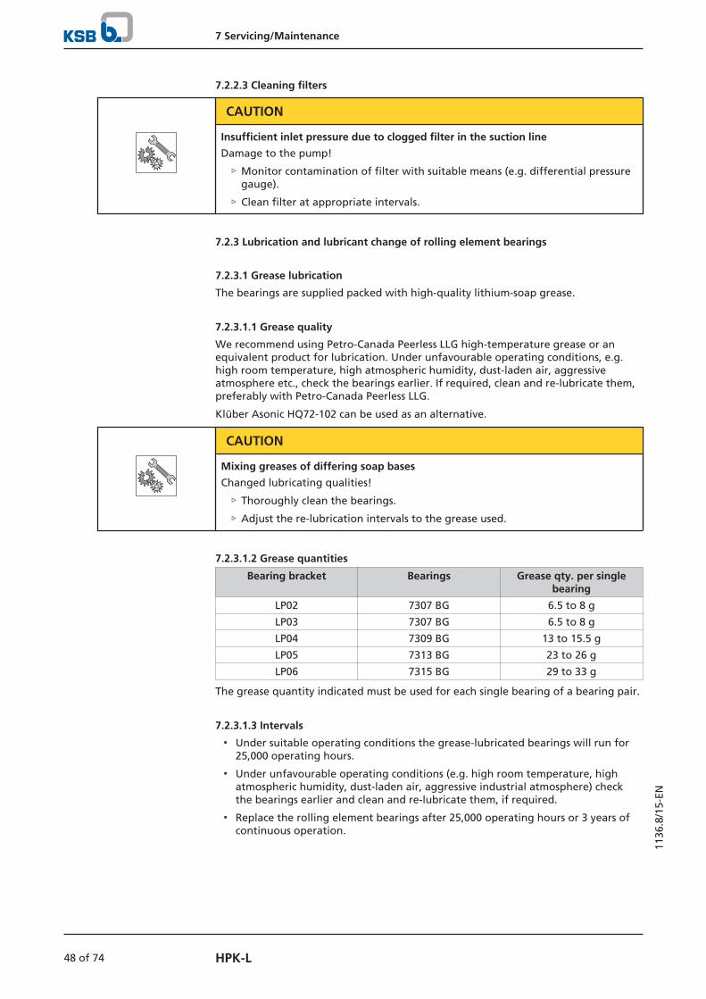
7 Servicing/Maintenance
48 of 74 HPK-L
1136
.8/1
5-EN
7.2.2.3 Cleaning filters
CAUTION
Insufficient inlet pressure due to clogged filter in the suction line
Damage to the pump!
▷ Monitor contamination of filter with suitable means (e.g. differential pressuregauge).
▷ Clean filter at appropriate intervals.
7.2.3 Lubrication and lubricant change of rolling element bearings
7.2.3.1 Grease lubrication
The bearings are supplied packed with high-quality lithium-soap grease.
7.2.3.1.1 Grease quality
We recommend using Petro-Canada Peerless LLG high-temperature grease or anequivalent product for lubrication. Under unfavourable operating conditions, e.g.high room temperature, high atmospheric humidity, dust-laden air, aggressiveatmosphere etc., check the bearings earlier. If required, clean and re-lubricate them,preferably with Petro-Canada Peerless LLG.
Klüber Asonic HQ72-102 can be used as an alternative.
CAUTION
Mixing greases of differing soap bases
Changed lubricating qualities!
▷ Thoroughly clean the bearings.
▷ Adjust the re-lubrication intervals to the grease used.
7.2.3.1.2 Grease quantities
Bearing bracket Bearings Grease qty. per singlebearing
LP02 7307 BG 6.5 to 8 g
LP03 7307 BG 6.5 to 8 g
LP04 7309 BG 13 to 15.5 g
LP05 7313 BG 23 to 26 g
LP06 7315 BG 29 to 33 g
The grease quantity indicated must be used for each single bearing of a bearing pair.
7.2.3.1.3 Intervals
▪ Under suitable operating conditions the grease-lubricated bearings will run for25,000 operating hours.
▪ Under unfavourable operating conditions (e.g. high room temperature, highatmospheric humidity, dust-laden air, aggressive industrial atmosphere) checkthe bearings earlier and clean and re-lubricate them, if required.
▪ Replace the rolling element bearings after 25,000 operating hours or 3 years ofcontinuous operation.

7 Servicing/Maintenance
49 of 74HPK-L
1136
.8/1
5-EN
7.3 Drainage/cleaning
WARNING
Fluids handled, consumables and supplies which are hot and/or pose a healthhazard
Hazard to persons and the environment!
▷ Collect and properly dispose of flushing fluid and any fluid residues.
▷ Wear safety clothing and a protective mask if required.
▷ Observe all legal regulations on the disposal of fluids posing a health hazard.
If the pump set has handled fluids whose residues could lead to corrosion damage inthe presence of atmospheric humidity or could ignite upon contact with oxygen, thepump set must be neutralised, and anhydrous inert gas must be blown through thepump to ensure drying.
Use connection 6B to drain the fluid handled (see drawing of auxiliary connections).
7.4 Dismantling the pump set
7.4.1 General information/Safety regulations
DANGER
Insufficient preparation of work on the pump (set)
Risk of injury!
▷ Properly shut down the pump set.
▷ Close the shut-off elements in the suction line and discharge line.
▷ Drain the pump and release the pump pressure. (ð Section 7.3, Page 49)
▷ Shut off any auxiliary connections.
▷ Allow the pump set to cool down to ambient temperature.
WARNING
Unqualified personnel performing work on the pump (set)
Risk of injury!
▷ Always have repair work and maintenance work performed by specially trained,qualified personnel.
WARNING
Hot surface
Risk of injury!
▷ Allow the pump set to cool down to ambient temperature.
WARNING
Improper lifting/moving of heavy assemblies or components
Personal injury and damage to property!
▷ Use suitable transport devices, lifting equipment and lifting tackle to moveheavy assemblies or components.

7 Servicing/Maintenance
50 of 74 HPK-L
1136
.8/1
5-EN
WARNING
Thin metal foil used as carrier material in joint rings
Risk of injury (cuts)!
▷ Wear protective clothing.
▷ Always use an appropriate tool to remove joint rings.
Observe the general safety instructions and information. (ð Section 7.1, Page 44)
For any work on the motor, observe the instructions of the relevant motormanufacturer.
For dismantling and reassembly observe the exploded views and the generalassembly drawing.
In the event of damage you can always contact our service departments.
NOTE
After a prolonged period of operation the individual components may be hard topull off the shaft. If this is the case, use a brand name penetrating agent and/or - ifpossible - an appropriate puller.
NOTE
We recommend placing a drip pan under the pump along its entire length to collectany fluid escaping during dismantling.
7.4.2 Preparing the pump set
1. Interrupt the power supply and secure the pump against unintentional start-up.
2. Disconnect and remove all auxiliary pipework.
3. Remove the coupling guard.
4. Remove the coupling spacer, if any.
7.4.3 Removing the motor
NOTE
On pump sets with spacer-type couplings, the back pull-out unit can be removedwhile the motor remains bolted to the baseplate.
WARNING
Motor tipping over
Risk of crushing hands and feet!
▷ Suspend or support the motor to prevent it from tipping over.
1. Disconnect the motor from the power supply.
2. Unbolt the motor from the baseplate.
3. Shift the motor to separate it from the pump.
7.4.4 Removing the back pull-out unit
ü On pump sets without spacer-type coupling, the motor has been removed.
ü The notes and steps stated in (ð Section 7.4.1, Page 49) to (ð Section 7.4.3, Page 50) have been observed/carried out.

7 Servicing/Maintenance
51 of 74HPK-L
1136
.8/1
5-EN
WARNING
Back pull-out unit tilting
Risk of crushing hands and feet!
▷ Suspend or support the bearing bracket at the pump end.
1. If required, suspend or support bearing bracket 330 to prevent it from tilting.
2. Unbolt support foot 183 from the baseplate.
3. Loop a rope tightly around the neck of bearing bracket 330.
4. Undo hexagon nut 920.01 at the volute casing.
5. Pull the back pull-out unit out of the volute casing.
6. If necessary, clean the threaded holes for forcing screws 901.31 and use forcingscrews.
7. Remove and dispose of joint ring 411.10.
8. Place the back pull-out unit on a clean and level surface.
7.4.5 Removing the impeller
ü The notes and steps stated in (ð Section 7.4.1, Page 49) to (ð Section 7.4.4, Page 50) have been observed/carried out.
ü The back pull-out unit has been placed in a clean and level assembly area.
1. Undo hexagon nut 920.95.
2. Remove disc 550.87 from shaft 210.
3. Pull impeller 230 off shaft 210.
4. Remove keys 940.01.
7.4.6 Removing the plain bearing
ü The notes and steps stated in (ð Section 7.4.1, Page 49) to(ð Section 7.4.5, Page 51) have been observed/carried out.
1. Pull cup spring 950.23 and locking ring 515.21 off the shaft. If possible, also pullout locking ring 515.22 and bearing sleeve 529.21 in the process.
7.4.7 Removing the mechanical seals
Pump set with KSB mechanical seal 4HL
ü The notes and steps stated in (ð Section 7.4.1, Page 49) to(ð Section 7.4.6, Page 51) have been observed/carried out.
ü The bearing bracket has been placed in a clean and level assembly area.
1. Undo the socket head cap screw or grub screw in the coupling hub and use apuller to pull the coupling half off the pump shaft. Remove key 940.02.
2. Loosen hexagon head bolts 901.84 and remove fan hood 832.
3. Undo hexagon socket head cap screws 914.02.
4. Gently drive shaft 210 together with rolling element bearings 320.02, bearingcover 360.02, fan impeller 831, mating ring carrier 476 and mechanical seal 433out of bearing bracket 330 towards the drive end.
5. Undo grub screws 904.32.
6. Pull mechanical seal 433.02 off shaft 210 towards the pump end.
7. Pull mating ring carrier 476 off at the pump end together with the mating ringof the mechanical seal.
8. Take the mating ring out of mating ring carrier 476.

7 Servicing/Maintenance
52 of 74 HPK-L
1136
.8/1
5-EN
Pump set with standardised mechanical seal
ü The notes and steps stated in (ð Section 7.4.1, Page 49) to (ð Section 7.4.6, Page 51) have been observed/carried out.
ü The bearing has been placed in a clean and level assembly area.
1. Undo the socket head cap screw or grub screw in the coupling hub and use apuller to pull the coupling half off the pump shaft. Remove key 940.02.
2. Loosen hexagon head bolts 901.84 and remove fan hood 832.
3. Undo hexagon socket head cap screws 914.02.
4. Gently drive shaft 210 together with rolling element bearings 320.02, bearingcover 360.02, fan impeller 831, mating ring carrier 476 and mechanical seal 433out of bearing bracket 330 towards the drive end.
5. Undo grub screws 904.32.
6. Remove support disc 550.59 (LP02 and LP03 only) and O-ring 412.07.
7. Pull shaft sleeve 523 with mechanical seal 433.02 off shaft 210 towards thepump end.
8. Pull mating ring carrier 476 off at the pump end together with the mating ringof the mechanical seal.
9. Take the mating ring out of mating ring carrier 476.
10. For versions with mechanical seals in tandem arrangement only: Unscrew thegrub screw of the second mechanical seal and pull the seal off the shaft at thepump end.
11. For versions with mechanical seals in tandem arrangement only: Remove thesecond mating ring carrier 476.02 with the mating ring of the mechanical seal atthe pump end.
12. For versions with mechanical seals in tandem arrangement only: Remove themating ring from mating ring carrier 476.02.
7.4.8 Dismantling the bearings
NOTE
The bearings are packed with grease and must not be heated up for dismantling. Ifheated up, they must be re-packed with grease.
ü The notes and steps stated in (ð Section 7.4.1, Page 49) to(ð Section 7.4.7, Page 51) have been observed and carried out.
ü The shaft with the rolling element bearings has been placed in a clean and levelassembly area.
1. Unbend lock washer 931.01. Unscrew slotted round nut 920.21 (right-handthread). Remove lock washer 931.01, fan impeller 831, bearing cover 360.02,spacer sleeve 525.24 and drive-end ring 500.32.
2. For versions with bearing carriers LN02 to LN04 only: Pull bearing 320.02 off theshaft. Remove thrower 507.12, spacer sleeve 525.03 and pump-end ring 500.32from shaft 210.
3. For versions with bearing carriers LN05 and LN06 only: Pull bearings 320.02,321.02 off the shaft.
4. For versions with one mechanical seal and shaft seal ring only: Remove pump-end ring 500.32 from shaft 210.
5. For versions with one mechanical seal and shaft seal ring only: Remove O-ring412.03 and spacer sleeve 525.03.
6. For versions with one mechanical seal and two angular contact ball bearingsonly: Remove spacer sleeve 525.03 and thrower 507.12 from shaft 210.

7 Servicing/Maintenance
53 of 74HPK-L
1136
.8/1
5-EN
7.4.9 Removing the plain bearing bush
ü The notes and steps stated in (ð Section 7.4.1, Page 49) to (ð Section 7.4.8, Page 52) have been observed/carried out.
ü The bearing bracket has been placed in a clean and level assembly area.
1. Remove circlip 932.05.
2. Completely pull bearing bush 545.21 and tolerance ring 500.61 out of thebearing bracket.
7.5 Reassembling the pump set
7.5.1 General information/Safety regulations
WARNING
Improper lifting/moving of heavy assemblies or components
Personal injury and damage to property!
▷ Use suitable transport devices, lifting equipment and lifting tackle to moveheavy assemblies or components.
CAUTION
Improper reassembly
Damage to the pump!
▷ Reassemble the pump (set) in accordance with the general rules of soundengineering practice.
▷ Use original spare parts only.
Sequence Always reassemble the pump in accordance with the corresponding general assemblydrawing.
Sealing elements ▪ Gaskets
– Always use new gaskets, making sure that they have the same thickness asthe old ones.
– Always fit gaskets of asbestos-free materials or graphite without usinglubricants (e.g. copper grease, graphite paste).
▪ O-rings
– Never use O-rings that have been made by cutting an O-ring cord to size andgluing the ends together.
CAUTION
Contact of O-ring with graphite or similar material
Fluid could escape!
▷ Do not coat O-ring with graphite or similar material.
▷ Use animal fats or lubricants based on silicone or PTFE.
▪ Assembly adhesives
– For gaskets, avoid the use of assembly adhesives if possible.
– If assembly adhesives are required, use a commercially available contactadhesive (e.g. "Pattex").
– Only apply adhesive at selected points and in thin layers.
– Never use quick-setting adhesives (cyanoacrylate adhesives).
– Coat the locating surfaces of the individual components and screwedconnections with graphite or similar before reassembly.
– Prior to reassembly, screw back any forcing screws and adjusting screws.

7 Servicing/Maintenance
54 of 74 HPK-L
1136
.8/1
5-EN
Tightening torques For reassembly, tighten all screws and bolts as specified in this manual.
7.5.2 Installing the bearings
Version with one mechanical seal and two angular contact ball bearings or versionwith two mechanical seals in tandem arrangement and one deep groove ballbearing or one four-point bearing
ü The individual parts have been placed in a clean and level assembly area.
ü All dismantled parts have been cleaned and checked for wear.
ü Any damaged or worn parts have been replaced by original spare parts.
ü The sealing surfaces have been cleaned.
1. For versions with one mechanical seal only: Slide thrower 507.12 onto shaft 210.
2. Slide spacer sleeve 525.03 (for LP02 to LP04 only) and ring 500.32 onto shaft 210.
3. Press ball bearing 320.02 onto the shaft as far as it will go.The standard pump set is fitted with two angular contact ball bearings. Versionwith two mechanical seals are fitted with either a deep groove ball bearing or afour-point bearing, depending on the pump size.
NOTE
Angular contact ball bearings must be installed in back-to-back arrangement.Angular contact ball bearings installed in pairs must always be from the samemanufacturer.
NOTE
The bearings are packed with grease and must not be heated up for reassembly. Ifheated up, they must be re-packed with grease!
4. Slide spacer sleeve 525.24 onto shaft 210 and use a C-spanner to tighten slottedround nut 920.21 without lock washer 931.01. Then unscrew the slotted roundnut again.
5. Slide ring 500.32, bearing cover 360.02 and fan impeller 831 onto the shaft.
6. Apply a few spots of Molykote to the contact faces of the lock washer and thelocknut. Then slide on lock washer 931.01.
7. Tighten locknut 920.21 and bend over the lock washer.
Version with one mechanical seal, lip seal and one deep groove ball bearing or onefour-point bearing
ü The individual parts have been placed in a clean and level assembly area.
ü All dismantled parts have been cleaned and checked for wear.
ü Any damaged or worn parts have been replaced by original spare parts.
ü The sealing surfaces have been cleaned.
NOTE
The bearings are packed with grease and must not be heated up for reassembly. Ifheated up, they must be re-packed with grease!
1. Slide spacer sleeve 525.03 and ring 500.32 onto shaft 210.
2. Insert O-ring 412.03 in spacer sleeve 525.03.
3. Press ball bearing 320.02/321.02 onto the shaft as far as it will go.
4. Slide spacer sleeve 525.24 onto shaft 210 and use a C-spanner to tighten slottedround nut 920.21 without lock washer 931.01. Then unscrew the slotted roundnut again.
5. Slide ring 500.32, bearing cover 360.02 and fan impeller 831 onto the shaft.

7 Servicing/Maintenance
55 of 74HPK-L
1136
.8/1
5-EN
6. Apply a few spots of Molykote to the contact faces of the lock washer and thelocknut. Then slide on lock washer 931.01.
7. Tighten locknut 920.21 and bend over the lock washer.
8. Press lip seal 421 into mating ring carrier 476.
DANGER
Excessive temperature caused by defective bearing seal
Explosion hazard!
▷ Grease the lip seal. Observe the indicated grease quality. (ð Section 7.2.3.1.1, Page 48)
9. Grease the sealing lip of the lip seal with rolling element bearing grease (ð Section 7.2.3.1.1, Page 48) .
10. Apply approx. 5 g of grease in the lower area between spacer ring 525.03 andthe rear (bearing side) of lip seal 421.
7.5.3 Installing the mechanical seal
Fig. 20: Installing the mechanical seal
1 Markings on the shaft 2 Face of shaft sleeve
3 Bearing brackets LP02, LP03 4 Bearing brackets LP04, LP05, LP06
Pump set with KSB mechanical seal 4HL
ü The notes and steps stated in (ð Section 7.5.1, Page 53) to (ð Section 7.5.2, Page 54) have been observed/carried out.
ü The individual parts have been placed in a clean and level assembly area.
ü All dismantled parts have been cleaned and checked for wear.
ü Any damaged or worn parts have been replaced by original spare parts.
ü The sealing surfaces have been cleaned.

7 Servicing/Maintenance
56 of 74 HPK-L
1136
.8/1
5-EN
NOTE
Only remove the protective wrapping of the seal faces immediately before assemblytakes place.
1. Insert the mating ring and the secondary seals of the mechanical seal intomating ring carrier 476 and slide them onto the shaft from the pump end.
2. Slide the rotating components of the mechanical seal (torque-transmittingelement, springs, primary ring, secondary seal, etc.) onto the shaft as a completesub-assembly.
3. For LP02 and LP03: The mechanical seal is correctly positioned on the shaft whenits pump-end face (see "2" in Fig. "Installing the mechanical seal") is alignedwith the mark on the shaft (see "1" in Fig. "Installing the mechanical seal").On shafts without marking, align the mechanical seal with the shaft shoulder. The mechanical seal is generally positioned correctly when the bolt head islocated in the centre of the slotted hole (marking) (see Fig. "Correct position ofKSB mechanical seal" )
1
2Fig. 21: Correct position of the KSB mechanical seal
1 Markings on the mechanical seal 2 Bolt head
4. Tighten the grub screws with cup point evenly, alternately and gradually to thetorques specified, depending on the nominal thread diameter. Grub screws with cup point may be used without applying a thread-lockingagent. Grub screws with cup point must not be re-used.
Table 19: Tightening torques for grub screws with cup point
Thread Tightening torque [Nm]
M6 8
M8 15
M10 20
5. Verify the correct axial position of mechanical seal 433.02 on shaft 210.
CAUTION
Incorrect position of the mechanical seal
Hot fluid or steam may spurt out during operation!
▷ Make sure the mechanical seal is seated properly.
Pump set with standardised mechanical seal
ü The notes and steps stated in (ð Section 7.5.1, Page 53) to (ð Section 7.5.2, Page 54) have been observed/carried out.
ü The individual parts have been placed in a clean and level assembly area.
ü All dismantled parts have been cleaned and checked for wear.
ü Any damaged or worn parts have been replaced by original spare parts.
ü The sealing surfaces have been cleaned.

7 Servicing/Maintenance
57 of 74HPK-L
1136
.8/1
5-EN
NOTE
Only remove the protective wrapping of the seal faces immediately before assemblytakes place.
1. Versions with two mechanical seal in tandem arrangement: Insert the matingring of the second mechanical seal into mating ring carrier 476.02 and slide bothonto the shaft from the pump end.
2. Versions with mechanical seals in tandem arrangement: Slide the primary ringonto the shaft until it reaches the shaft shoulder. Secure it with a grub screw.
3. Insert the mating ring and the secondary seals of the mechanical seal intomating ring carrier 476 and slide them onto the shaft from the pump end.
4. Slide the rotating components of the mechanical seal (torque-transmittingelement, springs, primary ring, secondary seal, etc.) onto shaft sleeve 523 as acomplete sub-assembly. Slide this sub-assembly on until it will not go anyfurther. Then lock it with the grub screws.
5. For LP02 and LP03: Slide shaft sleeve 523 onto shaft 210. The shaft sleeve is correctly positioned on the shaft when its pump-end face("2" see Fig. "Installing the mechanical seal") is aligned with the mark on theshaft ("1" see Fig. "Installing the mechanical seal"). Guide O-ring 412.07 andsupport disc 550.59 carefully along the shaft and press them into the recess ofshaft sleeve 523.For LP04, LP05 and LP06: Insert O-ring 412.07 into shaft sleeve 523. Carefullyguide the shaft sleeve along the shaft.On shafts without marking, align the shaft sleeve with the shaft shoulder (seeFig. "Installing the mechanical seal").
6. Screw in grub screws 904.32 by several turns to hold the support disc in place.
7. Firmly tighten all grub screws 904.32.
8. Verify the correct axial position of shaft sleeve 523 and mechanical seal 433.02on shaft 210.
CAUTION
Incorrect position of the mechanical seal
Hot fluid or steam may spurt out during operation!
▷ Make sure the mechanical seal is seated properly.
7.5.4 Fitting the plain bearing bush
ü The notes and steps stated in (ð Section 7.5.1, Page 53) to (ð Section 7.5.3, Page 55) have been observed/carried out.
1. If bearing bush 545.21 is replaced with a new one, a new tolerance ring 500.61must be fitted in the corresponding groove of the bearing bracket.
CAUTION
Incorrect position of the bearing bush
Excessive bearing load during operation!
▷ Check that the groove is positioned correctly.
2. Swiftly and evenly press bearing bush 545.21 into the bearing bracket. (Risk offractures: do not subject it to any blows.) Check that the groove of the bearingbush is positioned correctly. The bearing bush is inserted correctly when itsgroove is on top (12 o’clock position).
3. Insert ring 932.05 into the groove of the bearing bracket to secure the bearingbush axially.

7 Servicing/Maintenance
58 of 74 HPK-L
1136
.8/1
5-EN
7.5.5 Fitting the bearing bracket
ü The notes and steps stated in (ð Section 7.5.1, Page 53) to(ð Section 7.5.4, Page 57) been observed/carried out.
1. Place guard 680 onto the bearing bracket.
2. Place O-ring 412.82 on the mating ring carrier.
3. Slide shaft 210 with all assembled components into the bearing bracket.
4. Fasten the bearing cover with hexagon socket head cap screws 914.02.
5. Carefully insert joint ring 411.11.
6. Place bearing bracket 330 into casing cover 161 and firmly tighten it with nuts920.04.
7.5.6 Fitting the plain bearing
ü The notes and steps stated in (ð Section 7.5.1, Page 53) to (ð Section 7.5.5, Page 58) have been observed/carried out.
1. Clean all parts of plain bearing (sleeve) 310.10 and make sure that there are nodirt particles between the conical surfaces of the bearing parts. Otherwise, theparts will not be centred correctly, which will result in failure of the plainbearing.
2. Prior to reassembly check whether the bearing parts and the impeller can beeasily fitted on shaft 210.
3. Slide locking ring 515.22, bearing sleeve 529.21, locking ring 515.21 and discspring 950.23 onto shaft 210.Mount disc springs 950.23 in such a way that the outside diameter of the discspring rests against locking ring 515.21.
7.5.7 Fitting the impeller
ü The notes and steps stated in (ð Section 7.5.1, Page 53) to(ð Section 7.5.6, Page 58) have been observed/carried out.
ü The bearing assembly/mechanical seal as well as the individual parts have beenplaced in a clean and level assembly area.
ü All dismantled parts have been cleaned and checked for wear.
ü Any damaged or worn parts have been replaced by original spare parts.
ü The sealing surfaces have been cleaned.
ü Impeller bore, shaft and keyways are clean and free from burrs.
1. Insert key 940.01. Guide impeller 230 onto shaft 210.
2. Insert disc 550.87 and tighten hexagon nut 920.95 with a torque wrench. - Tighten the nut evenly to prevent damage to the bearings. - Rotate the shaft by hand every now and then while tightening the nut (theshaft must be easy to rotate). Stop the tightening procedure if the shaft seemsto be blocked. Loosen the nut and repeat the tightening procedure. If the shaftis blocked repeatedly, dismantle the parts. Check that they are clean andcorrectly dimensioned.
3. After the rotating pump assembly (pump without casing) has been assembled,check the radial shaft run-out at the impeller. Maximum permissible run-out: 0.15 mm.
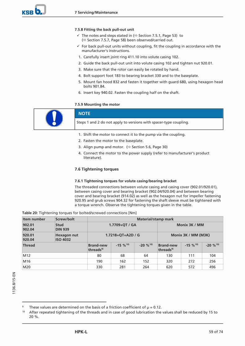
7 Servicing/Maintenance
59 of 74HPK-L
1136
.8/1
5-EN
7.5.8 Fitting the back pull-out unit
ü The notes and steps stated in (ð Section 7.5.1, Page 53) to(ð Section 7.5.7, Page 58) been observed/carried out.
ü For back pull-out units without coupling, fit the coupling in accordance with themanufacturer's instructions.
1. Carefully insert joint ring 411.10 into volute casing 102.
2. Guide the back pull-out unit into volute casing 102 and tighten nut 920.01.
3. Make sure that the rotor can easily be rotated by hand.
4. Bolt support foot 183 to bearing bracket 330 and to the baseplate.
5. Mount fan hood 832 and fasten it together with guard 680, using hexagon headbolts 901.84.
6. Insert key 940.02. Fasten the coupling half on the shaft.
7.5.9 Mounting the motor
NOTE
Steps 1 and 2 do not apply to versions with spacer-type coupling.
1. Shift the motor to connect it to the pump via the coupling.
2. Fasten the motor to the baseplate.
3. Align pump and motor. (ð Section 5.6, Page 30)
4. Connect the motor to the power supply (refer to manufacturer's productliterature).
7.6 Tightening torques
7.6.1 Tightening torques for volute casing/bearing bracket
The threaded connections between volute casing and casing cover (902.01/920.01),between casing cover and bearing bracket (902.04/920.04) and between bearingcover and bearing bracket (914.02) as well as the hexagon nut for impeller fastening920.95 and grub screws 904.32 for fastening the shaft sleeve must be tightened witha torque wrench. Observe the tightening torques given in the table.
Table 20: Tightening torques for bolted/screwed connections [Nm]
Item number Screw/bolt Material/stamp mark
902.01902.04
Stud DIN 939
1.7709+QT / GA Monix 3K / MM
920.01920.04
Hexagon nutISO 4032
1.7218+QT+A2D / G Monix 3K / MM (M3K)
Thread Brand-newthreads9)
-15 %10) -20 %10) Brand-newthreads9)
-15 %10) -20 %10)
M12 80 68 64 130 111 104
M16 190 162 152 320 272 256
M20 330 281 264 620 572 496
9 These values are determined on the basis of a friction coefficient of μ = 0.12.10 After repeated tightening of the threads and in case of good lubrication the values shall be reduced by 15 to
20 %.

7 Servicing/Maintenance
60 of 74 HPK-L
1136
.8/1
5-EN
914.02 Hexagon sockethead cap screwDIN 7984
8.8 / 8.8
Thread Brand-new threads9) -15 %10) -20 %10)
M8 25 21 20
M10 35 30 28
M12 59 50 47
904.32 Grub screwDIN 916
A4-50 / -
Thread
M6 5 - 9
920.95 Hexagon nutISO 8673
A4 / A4
Thread Brand-new threads -15 %10) -20 %10)
M16x1,5 100 85 80
M20x1,5 120 102 96
M24x1,5 150 128 120
M30x2 350 298 280
7.7 Spare parts stock
7.7.1 Ordering spare parts
Always quote the following data when ordering replacement or spare parts:
▪ Order number
▪ Order item number
▪ Type series
▪ Size
▪ Material variant
▪ Year of construction
Refer to the name plate for all data.
Also specify the following data:
▪ Part number and description
▪ Quantity of spare parts
▪ Shipping address
▪ Mode of dispatch (freight, mail, express freight, air freight)
7.7.2 Recommended spare parts stock for 2 years' operation to DIN 24296
Table 21: Quantity of spare parts for recommended spare parts stock
Part No. Description Number of pumps (including stand-by pumps)
2 3 4 5 6 and 7 8 and 9 10 andmore
Quantity of spare parts
210 Shaft 1 1 2 2 2 3 30 %
230 Impeller 1 1 2 2 2 3 30 %
310.10 Plain bearing (product-lubricated)
2 3 4 5 6 8 100 %
320.02 Angular contact ball bearing(set)
1 1 2 2 3 4 55 %
330 Bearing bracket - - - - - 1 2 pcs.
433 Mechanical seal 1 1 2 2 2 3 25 %

7 Servicing/Maintenance
61 of 74HPK-L
1136
.8/1
5-EN
Part No. Description Number of pumps (including stand-by pumps)
2 3 4 5 6 and 7 8 and 9 10 andmore
Quantity of spare parts
502.0111) Casing wear ring 2 2 2 3 3 4 50 %
523 Shaft sleeve 1 1 1 2 2 2 20 %
545.21 Bearing bush (product-lubricated)
2 3 4 5 6 8 100 %
--- Set of sealing elements 4 6 8 8 9 12 150 %
7.7.3 Interchangeability of pump components
Components featuring the same number in a column are interchangeable.
NOTE
Volute casing 102 and impeller 230 are not interchangeable between differentpump sizes.
Table 22: Interchangeability of pump components
Bea
rin
g b
rack
et
Size
Description
Cas
ing
co
ver
Sup
po
rt f
oo
t
Shaf
t
Plai
n b
eari
ng
An
gu
lar
con
tact
bal
l bea
rin
g
An
gu
lar
con
tact
bal
l bea
rin
g
Bea
rin
g b
rack
et
Bea
rin
g c
ove
r
Mec
han
ical
sea
l
Mat
ing
rin
g c
arri
er
Cas
ing
wea
r ri
ng
Thro
wer
Shaf
t sl
eeve
Spac
er s
leev
e
Spac
er s
leev
e
Bea
rin
g b
ush
Gu
ard
Fan
imp
elle
r
Fan
ho
od
Hex
ago
n n
ut
Part No.
161
183
210
310.
10
320.
02
321
330
360
433.
01
433.
02
476.
01
476.
02
502.
01
507.
01
523
525.
03
525.
24
545.
21
680
831
832
920.
95
LP02 32-125 1 1 1 1 1 1 1 1 1 1 1 1 1 1 1 2 1 1 1 1 1 1
25-160 1 2 1 1 1 1 1 1 1 1 1 1 25 1 1 2 1 1 1 1 1 1
32-160 1 2 1 1 1 1 1 1 1 1 1 1 1 1 1 2 1 1 1 1 1 1
40-160 1 2 1 1 1 1 1 1 1 1 1 1 2 1 1 2 1 1 1 1 1 1
50-160 1 3 1 1 1 1 1 1 1 1 1 1 3 1 1 2 1 1 1 1 1 1
25-200 2 3 1 1 1 1 1 1 1 1 1 1 25 1 1 2 1 1 1 1 1 1
32-200 2 3 1 1 1 1 1 1 1 1 1 1 1 1 1 2 1 1 1 1 1 1
40-200 2 3 1 1 1 1 1 1 1 1 1 1 2 1 1 2 1 1 1 1 1 1
50-200 2 3 1 1 1 1 1 1 1 1 1 1 3 1 1 2 1 1 1 1 1 1
LP03 65-160 3 4 2 2 1 1 2 1 2 2 2 2 7 1 2 2 1 2 1 1 1 1
80-160 3 5 2 2 1 1 2 1 2 2 2 2 9 1 2 2 1 2 1 1 1 1
65-200 4 5 2 2 1 1 2 1 2 2 2 2 8 1 2 2 1 2 1 1 1 1
80-200 4 5 2 2 1 1 2 1 2 2 2 2 10 1 2 2 1 2 1 1 1 1
100-200 4 6 2 2 1 1 2 1 2 2 2 2 12 1 2 2 1 2 1 1 1 1
32-250 5 5 2 2 1 1 2 1 2 2 2 2 6 1 2 2 1 2 1 1 1 1
40-250 5 5 2 2 1 1 2 1 2 2 2 2 5 1 2 2 1 2 1 1 1 1
50-250 5 5 2 2 1 1 2 1 2 2 2 2 4 1 2 2 1 2 1 1 1 1
11 Provided as a standard feature on HPK-LS and HPK-LS4 only, optional feature only on HPK-LE and HPK-LE4

7 Servicing/Maintenance
62 of 74 HPK-L
1136
.8/1
5-EN
Bea
rin
g b
rack
et
Size
Description
Cas
ing
co
ver
Sup
po
rt f
oo
t
Shaf
t
Plai
n b
eari
ng
An
gu
lar
con
tact
bal
l bea
rin
g
An
gu
lar
con
tact
bal
l bea
rin
g
Bea
rin
g b
rack
et
Bea
rin
g c
ove
r
Mec
han
ical
sea
l
Mat
ing
rin
g c
arri
er
Cas
ing
wea
r ri
ng
Thro
wer
Shaf
t sl
eeve
Spac
er s
leev
e
Spac
er s
leev
e
Bea
rin
g b
ush
Gu
ard
Fan
imp
elle
r
Fan
ho
od
Hex
ago
n n
ut
Part No.
161
183
210
310.
10
320.
02
321
330
360
433.
01
433.
02
476.
01
476.
02
502.
01
507.
01
523
525.
03
525.
24
545.
21
680
831
832
920.
95
LP03 65-250 5 6 2 2 1 1 2 1 2 2 2 2 8 1 2 2 1 2 1 1 1 1
80-250 5 7 2 2 1 1 2 1 2 2 2 2 11 1 2 2 1 2 1 1 1 1
40-315 6 6 2 2 1 1 2 1 2 2 2 2 5 1 2 2 1 2 1 1 1 1
50-315 6 7 2 2 1 1 2 1 2 2 2 2 7 1 2 2 1 2 1 1 1 1
LP04 100-250 5 8 3 2 2 2 3 2 3 3 3 3 13 2 3 2 2 2 2 2 2 2
125-250 5 9 3 2 2 2 3 2 3 3 3 3 15 2 3 2 2 2 2 2 2 2
150-250 5 10 3 2 2 2 3 2 3 3 3 3 16 2 3 2 2 2 2 2 2 2
65-315 6 8 3 2 2 2 3 2 3 3 3 3 9 2 3 2 2 2 2 2 2 2
80-315 6 9 3 2 2 2 3 2 3 3 3 3 12 2 3 2 2 2 2 2 2 2
100-315 6 9 3 2 2 2 3 2 3 3 3 3 14 2 3 2 2 2 2 2 2 2
125-315 6 10 3 2 2 2 3 2 3 3 3 3 16 2 3 2 2 2 2 2 2 2
80-400 7 10 3 2 2 2 3 2 3 3 3 3 27 2 3 2 2 2 2 2 2 2
100-400 7 10 3 2 2 2 3 2 3 3 3 3 14 2 3 2 2 2 2 2 2 2
125-400 7 11 3 2 2 2 3 2 3 3 3 3 15 2 3 2 2 2 2 2 2 2
LP05 200-250 8 13 4 3 4 4 4 3 4 4 4 4 17 3 4 3 3 3 3 3 3 3
150-315 9 12 4 3 4 4 4 3 4 4 4 4 2 3 4 3 3 3 3 3 3 3
200-315 9 13 4 3 4 4 4 3 4 4 4 4 19 3 4 3 3 3 3 3 3 3
250-315 9 16 5 3 4 4 4 3 4 4 4 4 21 3 4 3 3 3 3 3 3 3
150-400 10 12 5 3 4 4 4 3 4 4 4 4 18 3 4 3 3 3 3 3 3 3
200-400 10 13 5 3 4 4 4 3 4 4 4 4 20 3 4 3 3 3 3 3 3 3
150-500 11 14 5 3 4 4 4 3 4 4 4 4 18 3 4 3 3 3 3 3 3 3
200-500 11 17 5 3 4 4 4 3 4 4 4 4 28 3 4 3 3 3 3 3 3 3
LP06 250-400 12 17 6 4 5 5 5 4 5 5 5 5 22 4 5 4 4 4 3 3 3 4
250-500 13 15 6 4 5 5 5 4 5 5 5 5 23 4 5 4 4 4 3 3 3 4

8 Trouble-shooting
63 of 74HPK-L
1136
.8/1
5-EN
8 Trouble-shooting
WARNING
Improper work to remedy faults
Risk of injury!
▷ For any work performed to remedy faults, observe the relevant informationgiven in this operating manual and/or in the product literature provided by theaccessories manufacturer.
If problems occur that are not described in the following table, consultation with theKSB service is required.
A Pump delivers insufficient flow rate
B Motor is overloaded
C Excessive discharge pressure
D Increased bearing temperature
E Leakage at the pump
F Excessive leakage at the shaft seal
G Vibrations during pump operation
H Impermissible temperature increase in the pump
Table 23: Trouble-shooting
A B C D E F G H Possible cause Remedy12)
✘ - - - - - - - Pump delivers against an excessivelyhigh pressure.
Re-adjust to duty point.Check system for impurities.Fit a larger impeller.13)
Increase the speed (turbine, I.C. engine).
✘ - - - - - ✘ ✘ Pump or piping are not completelyvented or primed.
Vent and/or prime.
✘ - - - - - - - Supply line or impeller clogged Remove deposits in the pump and/or piping.
✘ - - - - - - - Formation of air pockets in the piping Alter piping layout.Fit vent valve.
✘ - - - - - ✘ ✘ Suction lift is too high/NPSHavailable (positive suction head) is toolow.
Check/alter fluid level.Install pump at a lower level.Fully open the shut-off element in the suctionline.Change suction line, if the friction losses in thesuction line are too high.Check any strainers installed/suction opening.Observe permissible speed of pressure fall.
✘ - - - - - - - Air intake at the shaft seal Clean barrier fluid duct, supply external barrierfluid, if necessary, or increase barrier fluidpressure.Replace shaft seal.
✘ - - - - - - - Wrong direction of rotation Check the electrical connection of the motorand the control system, if any.
✘ - - - - - - - Speed is too low.13)
- Operation with frequency inverter- Operation without frequency inverter
- Increase voltage/frequency at the frequencyinverter in the permissible range.- Check voltage.
✘ - - - - - ✘ - Impeller Replace worn components by new ones.
12 Pump pressure must be released before attempting to remedy faults on parts which are subjected to pressure.13 Contact KSB.

8 Trouble-shooting
64 of 74 HPK-L
1136
.8/1
5-EN
A B C D E F G H Possible cause Remedy12)
- ✘ - - - - ✘ - Pump back pressure is lower thanspecified in the purchase order.
Re-adjust to duty point. In the case of persistent overloading, turndown impeller.13)
- ✘ - - - - - - Density or viscosity of fluid handledhigher than stated in purchase order
Contact KSB.
- ✘ ✘ - - - - - Speed is too high. Reduce speed.13)
- - - - - ✘ - - Use of unsuitable materials Change the material combination.
- - - - ✘ - - - Defective gasket Fit new gasket between volute casing anddischarge cover.
- - - - - ✘ - - Worn shaft seal Fit new shaft seal.Check flushing liquid/barrier fluid.
✘ - - - - ✘ - - Score marks or roughness on shaftprotecting sleeve / shaft sleeve
Fit new shaft protecting sleeve / shaft sleeve.Fit new shaft seal.
- - - - - ✘ - - Dismantle to find out. Repair necessary.
- - - - - ✘ - - Vibrations during pump operation Correct suction conditions.Re-align the pump.Re-balance the impeller.Increase pressure at the pump suction nozzle.
- - - ✘ - ✘ ✘ - The pump set is misaligned. Re-align.
- - - ✘ - ✘ ✘ - Pump is warped or sympatheticvibrations in the piping.
Check the piping connections and secure fixingof pump; if required, reduce distances betweenthe pipe clamps.Fix the pipelines using anti-vibration material.
- - - ✘ - - - - Insufficient or excessive quantity oflubricant or unsuitable lubricant.
Top up, reduce or change lubricant.
- - - ✘ - - - - Non-compliance with specifiedcoupling distance
Correct distance according to generalarrangement drawing.
✘ ✘ - - - - - - Motor is running on two phases only. Replace the defective fuse.Check the electric cable connections.
- - - - - - ✘ - Rotor out of balance Clean the impeller.Re-balance the impeller.
- - - - - - ✘ - Defective bearing(s) Fit new bearing(s).
- - - ✘ - - ✘ ✘ Flow rate is too low. Increase the minimum flow rate.
- - - - - ✘ - - Incorrect inflow of circulation liquid Increase the free cross-section.

9 Related Documents
65 of 74HPK-L
1136
.8/1
5-EN
9 Related Documents
9.1 General assembly drawing with list of components
Fig. 22: General assembly drawing of HPK-LS/LE/LS4/LE4
Version with two mechanical seals and one deep groove ballbearing or one four-point bearing
Version with one mechanical seal with lip seal andone deep groove ball bearing or one four-pointbearing

9 Related Documents
66 of 74 HPK-L
1136
.8/1
5-EN
Table 24: List of components
Part No. Comprising Description
102 102 Volute casing
411.01/.02/.03/.04/.10 Joint ring
502.0114) Casing wear ring
561.0114) Parallel pin
902.01 Stud
903.01/.02/.03/.04 Screw plug
920.01 Hexagon nut
161 161 Casing cover
411.11 Joint ring
901.31 Hexagon head bolt
902.04 Stud
920.04 Hexagon nut
183 183 Support foot
901.04 Hexagon head bolt
930.01 Spring washer
210 210 Shaft
550.87 Disc
920.21 Slotted round nut
920.95 Hexagon nut
931.01 Lock washer
940.01/.02 Key
230 230 Impeller
310.10 310.10 Plain bearing (sleeve)
515.21/.22 Locking rings
529.21 Bearing sleeve
950.23 Disc spring
320.02 320.02 Angular contact ball bearing
330 330 Bearing bracket
330 330 Bearing bracket, complete
210 Shaft
310.10 Plain bearing (sleeve)
320.02 Angular contact ball bearing
360.02 Bearing cover
411.20 Joint ring
411.85 Joint ring
433.02 Mechanical seal
476 Mating ring carrier
500.32 Ring
500.61 Tolerance ring
507.12 Thrower
523 Shaft sleeve
525.03 Spacer sleeve
525.24 Spacer sleeve
545.21 Bearing bush
550.87 Disc
561.52 Grooved pin
14 For HPK-LS/LS4 only

9 Related Documents
67 of 74HPK-L
1136
.8/1
5-EN
Part No. Comprising Description
330 680 Guard
720.22 Barrel nipple
831 Fan impeller
832 Fan hood
901.84 Hexagon head bolt
903.20 Screw plug
903.85 Screw plug
914.02 Hexagon socket head cap screw
920.95 Hexagon nut
932.05 Circlip
523 523 Shaft sleeve
412.07 O-ring
550.59 Support disc (LP02 and LP03 only)
904.32 Grub screws
99-9 99-9 Set of sealing elements
Joint ring 411.01/.02/.03/.04/.10/.11/.20/.85
412.07/.82 O-ring
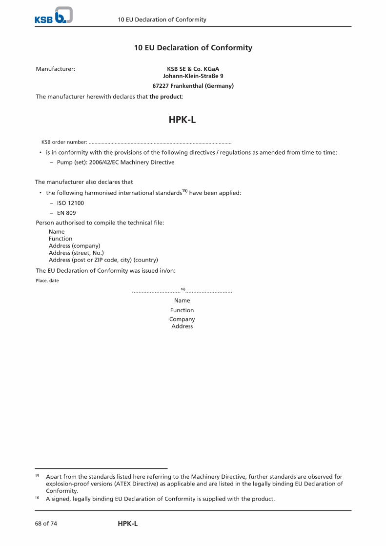
10 EU Declaration of Conformity
68 of 74 HPK-L
10 EU Declaration of Conformity
Manufacturer: KSB SE & Co. KGaAJohann-Klein-Straße 9
67227 Frankenthal (Germany)
The manufacturer herewith declares that the product:
HPK-L
KSB order number: ...................................................................................................
▪ is in conformity with the provisions of the following directives / regulations as amended from time to time:
– Pump (set): 2006/42/EC Machinery Directive
The manufacturer also declares that
▪ the following harmonised international standards15) have been applied:
– ISO 12100
– EN 809
Person authorised to compile the technical file:
NameFunction Address (company)Address (street, No.)Address (post or ZIP code, city) (country)
The EU Declaration of Conformity was issued in/on:
Place, date
..............................16).............................
Name
Function
CompanyAddress
15 Apart from the standards listed here referring to the Machinery Directive, further standards are observed forexplosion-proof versions (ATEX Directive) as applicable and are listed in the legally binding EU Declaration ofConformity.
16 A signed, legally binding EU Declaration of Conformity is supplied with the product.

11 Certificate of Decontamination
69 of 74HPK-L
1136
.8/1
5-EN
11 Certificate of Decontamination
Type: ................................................................................................................................
Order number /
Order item number17): ................................................................................................................................
Delivery date: ................................................................................................................................
Application: ................................................................................................................................
Fluid handled17): ................................................................................................................................
Please tick where applicable17):
⃞ ⃞ ⃞ ⃞ ⃞Corrosive Oxidising Flammable Explosive Hazardous to health
R⃞ ⃞ ⃞ ⃞ ⃞
Seriously hazardous tohealth
Toxic Radioactive Bio-hazardous Safe
Reason for return:17): ................................................................................................................................
Comments: ................................................................................................................................
................................................................................................................................
The product / accessories have been carefully drained, cleaned and decontaminated inside and outside prior to dispatch /placing at your disposal.
We herewith declare that this product is free from hazardous chemicals and biological and radioactive substances.
For mag-drive pumps, the inner rotor unit (impeller, casing cover, bearing ring carrier, plain bearing, inner rotor) has beenremoved from the pump and cleaned. In cases of containment shroud leakage, the outer rotor, bearing bracket lantern,leakage barrier and bearing bracket or intermediate piece have also been cleaned.
For canned motor pumps, the rotor and plain bearing have been removed from the pump for cleaning. In cases of leakage atthe stator can, the stator space has been examined for fluid leakage; if fluid handled has penetrated the stator space, it hasbeen removed.
⃞ No special safety precautions are required for further handling.
⃞ The following safety precautions are required for flushing fluids, fluid residues and disposal:
...............................................................................................................................................................
...............................................................................................................................................................
We confirm that the above data and information are correct and complete and that dispatch is effected in accordance with therelevant legal provisions.
.................................................................. ....................................................... .......................................................
Place, date and signature Address Company stamp
17 Required field
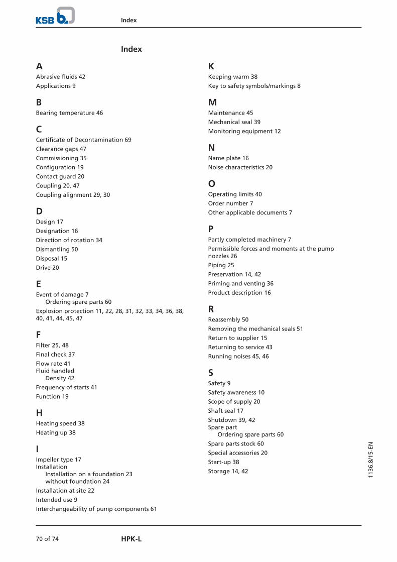
Index
70 of 74 HPK-L
1136
.8/1
5-EN
Index
AAbrasive fluids 42
Applications 9
BBearing temperature 46
CCertificate of Decontamination 69
Clearance gaps 47
Commissioning 35
Configuration 19
Contact guard 20
Coupling 20, 47
Coupling alignment 29, 30
DDesign 17
Designation 16
Direction of rotation 34
Dismantling 50
Disposal 15
Drive 20
EEvent of damage 7
Ordering spare parts 60
Explosion protection 11, 22, 28, 31, 32, 33, 34, 36, 38,40, 41, 44, 45, 47
FFilter 25, 48
Final check 37
Flow rate 41Fluid handled
Density 42
Frequency of starts 41
Function 19
HHeating speed 38
Heating up 38
IImpeller type 17Installation
Installation on a foundation 23without foundation 24
Installation at site 22
Intended use 9
Interchangeability of pump components 61
KKeeping warm 38
Key to safety symbols/markings 8
MMaintenance 45
Mechanical seal 39
Monitoring equipment 12
NName plate 16
Noise characteristics 20
OOperating limits 40
Order number 7
Other applicable documents 7
PPartly completed machinery 7
Permissible forces and moments at the pumpnozzles 26
Piping 25
Preservation 14, 42
Priming and venting 36
Product description 16
RReassembly 50
Removing the mechanical seals 51
Return to supplier 15
Returning to service 43
Running noises 45, 46
SSafety 9
Safety awareness 10
Scope of supply 20
Shaft seal 17
Shutdown 39, 42Spare part
Ordering spare parts 60
Spare parts stock 60
Special accessories 20
Start-up 38
Storage 14, 42
Index
71 of 74HPK-L
1136
.8/1
5-EN
TTemperature difference 38
Temperature limits 12
Transport 13Trouble-shooting
Causes of faults and remedies 63
WWarnings 8
Warranty claims 7


KSB SE & Co. KGaA
Johann-Klein-Straße 9 • 67227 Frankenthal (Germany)
Tel. +49 6233 86-0
www.ksb.com
1136
.8/1
5-EN
(013
1685
8)