111221-HATS-Paper on Trenchless Excavation by … · 1 Senior Engineer, Drainage Services...
12
1 Senior Engineer, Drainage Services Department 2 Associate, AECOM Asia Co. Ltd., Hong Kong 3 Chief Resident Engineer, AECOM Asia Co. Ltd., Hong Kong 4 Senior Resident Engineer, AECOM Asia Co. Ltd., Hong Kong 1 Trenchless Excavation by Horizontal Directional Drilling (HDD) Mr. SEIT Kin Fun, Raymond 1 , Mr. Lam, Yik Chong 2 , Mr. Mui, Wing Bun 3 , Mr. Tang, Sek Wai 4 ABSTRACT The Drainage Services Department (DSD) has commissioned the Harbour Area Treatment Scheme (HATS) Stage 2A - Sewage Conveyance System (SCS) to collect and convey the pre-treated sewage from existing Preliminary Treatment Works (PTW), located along the northern and south-western shoreline of Hong Kong Island, to the Stonecutters Island Sewage Treatment Works (SCISTW) for further treatment before final disposal into the western harbour through an existing submarine outfall. For the south-western part of Hong Kong Island, the construction Contract No. DC/2008/09 was awarded in 2009 for installing two High Density Polyethylene (HDPE) sewage pipes connecting Ap Lei Chau PTW to Aberdeen PTW. Each pipe is 600mm in (internal) diameter and about 1.4km in length, which will be installed at a depth of approximately 100m below sea level. A general layout plan is included. Installation of the HDPE sewage pipes will be carried out by a trenchless method called Horizontal Directional Drilling (HDD). HDD is a surface-launched drilling technique using bentonite slurry to support the drilled hole. The multi-stage operation consists of drilling a pilot hole along a designed path, then enlarging the pilot hole by reaming in stages, and followed by pulling of HDPE pipe into the enlarged hole. This paper will focus on the key design considerations and demonstrate the proper design approach on HDD installation. Last but not least, it will illustrate the major activities carried out on site at different stages and discuss the challenges encountered during the course of construction. East Lamma Channel
-
Upload
nguyennhan -
Category
Documents
-
view
215 -
download
0
Transcript of 111221-HATS-Paper on Trenchless Excavation by … · 1 Senior Engineer, Drainage Services...
1 Senior Engineer, Drainage Services Department
2 Associate, AECOM Asia Co. Ltd., Hong Kong
3 Chief Resident Engineer, AECOM Asia Co. Ltd., Hong Kong
4 Senior Resident Engineer, AECOM Asia Co. Ltd., Hong Kong
1
Trenchless Excavation by Horizontal Directional Drilling (HDD)
Mr. SEIT Kin Fun, Raymond1, Mr. Lam, Yik Chong2, Mr. Mui, Wing Bun3, Mr. Tang, Sek Wai4
ABSTRACT
The Drainage Services Department (DSD) has commissioned the Harbour Area Treatment Scheme
(HATS) Stage 2A - Sewage Conveyance System (SCS) to collect and convey the pre-treated sewage
from existing Preliminary Treatment Works (PTW), located along the northern and south-western
shoreline of Hong Kong Island, to the Stonecutters Island Sewage Treatment Works (SCISTW) for further
treatment before final disposal into the western harbour through an existing submarine outfall.
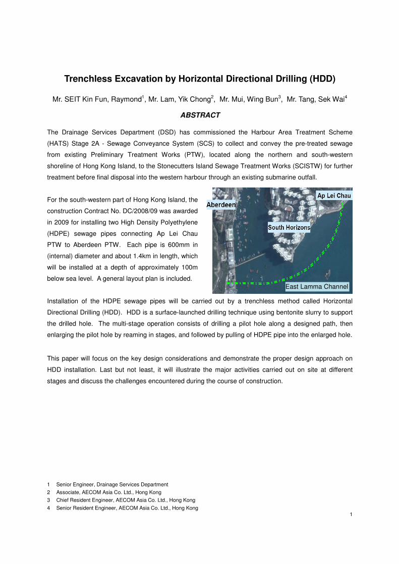
For the south-western part of Hong Kong Island, the
construction Contract No. DC/2008/09 was awarded
in 2009 for installing two High Density Polyethylene
(HDPE) sewage pipes connecting Ap Lei Chau
PTW to Aberdeen PTW. Each pipe is 600mm in
(internal) diameter and about 1.4km in length, which
will be installed at a depth of approximately 100m
below sea level. A general layout plan is included.
Installation of the HDPE sewage pipes will be carried out by a trenchless method called Horizontal
Directional Drilling (HDD). HDD is a surface-launched drilling technique using bentonite slurry to support
the drilled hole. The multi-stage operation consists of drilling a pilot hole along a designed path, then
enlarging the pilot hole by reaming in stages, and followed by pulling of HDPE pipe into the enlarged hole.
This paper will focus on the key design considerations and demonstrate the proper design approach on
HDD installation. Last but not least, it will illustrate the major activities carried out on site at different
stages and discuss the challenges encountered during the course of construction.
East Lamma Channel
2
1 INTRODUCTION
HDD is a high end technology transferred from oil exploration industry to nowadays microtunnelling for
installation of utilities such as power cables, telecom conduits, water mains and gas mains, etc. This
specialised technique is featured with a drilling rig on surface and a mud motor to drive the cutting tools
such as tri-cone bit and reamers. Before applying this technique for the HATS Stage 2A project, some
key design procedures were carried out during the preliminary design stage, which are important to
ensure a practical solution before tendering, and more importantly, all technical requirements and
concerns for the HDD works could be specified under the Contract for the Design & Build Contractor to
implement during the construction stage. Those key design procedures are discussed in the following
sections and be followed by the discussion on the HDD construction aspects.
2 KEY DESIGN PROCEDURES
Any construction activity, particular those major infrastructure development such as this project, may have
potential impacts to the surrounding. These impacts may either affect the HDD operation or be affecting
the nearby structures, which are important to be identified and assessed at the earliest stage. Until a
practical solution with proper design measures is developed, installation of sewers by HDD method can
be implemented. However, a successful HDD project is subject to the comprehensiveness of design,
which includes but is not limited to i) pre-construction survey, ii) alignment design, and iii) pipe design.
2.1 Pre-construction Survey
During the design phase, it is important for the Designer to collect accurate surface and subsurface
information, and to distribute them to the Contractor so that the actual drilling operation can be planned
with full assessment on all possible obstacles. A comprehensive pre-construction survey shall include the
surface survey and subsurface survey, which can result in fewer installation problems during the course
of HDD operation.
2.1.1 Surface Survey
The surface survey shall be conducted with sufficient extent covering the site area for equipment setup in
stages, storage locations, and drill path centreline with offset of 30m. By doing such surface survey, it is
targeted to obtain some general information such as:
- Ground features like roadways, footpaths, utility poles, overhead power lines, fire hydrants, etc.
- Culverts, open channels, manholes, switchboxes, etc.
- Structures such as buildings, tanks, bridges / piers, dangerous goods stores, etc.
- Mature trees, special plants / shrubs
- Geotechnical features such as man-made slopes, retaining walls and natural terrains, etc.

3
Under this HATS Stage 2A project, a few key structures / features have been identified and clearly
specified under the Contract with special care and attention, which include the natural terrain behind the
storage area, the gas tank adjacent to the launching site, and Tin Wan Praya Road (i.e. sole public
access road) in between the launching site and storage site.
2.1.2 Subsurface Survey
The subsurface survey is aimed to locate any potential features that may impact the HDD design or be
impacted by the HDD works. It mainly consists of the ground investigation (GI) and the utility survey.
2.1.2.1 Ground Investigation
A general geological review shall be carried out to determine the ground conditions likely be encountered
in the vicinity of the HDD alignment. After assessing the available GI data, a more comprehensive GI
shall be carried out which consists normally of taking exploratory boreholes to collect soil and rock
samples for laboratory testing. It is important at the design stage to determine if directional drilling is
practical and establish the most cost effective scheme to accomplish the drilling with adequate GI.
Through this comprehensive GI, key design parameters for soil can be determined such as soil
classification, shear strength, soil density, Standard Penetration Test (SPT) values; for rock, other
parameters such as rock characteristics, quality, unconfined compressive strength, hardness and
abrasiveness can be obtained.
Under this project, two nos. of project specific marine boreholes, namely 2A-DSI-MEMA-BH52M &
BH53M were drilled to collect the geological information along the alignment. Borehole 2A-DSI-MEMA-
BH52M is located 50m west of alignment near Chainage Q110.00. The rock was encountered at -
28.77mPD and was mainly slightly decomposed vitric Tuff. Another borehole 2A-DSI-MEMA-BH53M,
which is located at 22m east of the alignment near Chainage Q860.00, showed that the rockhead was
encountered at depth of -32.27mPD. The bedrock was typically described as strong to very strong,
slightly decomposed, fine to coarse ash vitric Tuff, with local shear zone encountered and eutaxite
occurred locally. These boreholes were intentionally driven with offset to the drilling path centreline to
reduce the possibility of drilling fluid inadvertently surfacing through the boreholes during the HDD
construction. 3 nos. of land boreholes, namely 2A-DSI-MEMA-BH36, BH37 & BH38, were driven at
Aberdeen PTW site, and 3 nos. of land boreholes, namely 2A-DSI-MEMA-BH40, BH145 & BH176, were
driven at Ap Lei Chau PTW area.
2.1.2.2 Utility Survey
Utility checking information is important for planning, designing and implementing HDD works. Similar to
other trenchless excavation, HDD is carried out as a blind boring and going through the ground without
knowing any possible obstacles in advance. A detailed research shall be performed, which may consist
4
of site reconnaissance, collecting as-built information from utility undertakers, and carrying out utility
detection by means of pipe locator, trenching, geophysical survey and probing, etc. All surveying details
shall be provided to the Contractor to avoid any potential conflicts during HDD construction by having
sufficient clearances to any concerned utilities. Under this project, a bundle of high voltage cross harbour
power lines is buried under the seabed, which may be affecting the HDD operation with magnetic
influence. In addition, other typical utilities such as drainage pipes, gas pipes, water mains, etc. are
identified during the design stage with all relevant details given to the Contractor before commencement
of HDD works.
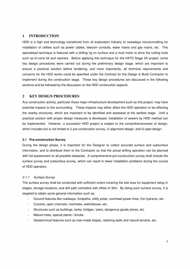
2.2 Alignment Design
In order to optimise the HDD alignment, the primary concern is to minimize the drilling length, which will
surely reduce the cost and time for the works. However, it is important to take into account other key
factors other than just the cost and time. These factors include the availability of working space at both
entry and exit locations and geological conditions along the drilling path. Once these factors are fully
addressed, the design path is subject to the configuration details which include i) penetration angles, ii)
radius of curvature, iii) directional accuracy and tolerance, and iv) vertical depth of cover.
2.2.1 Penetration Angles
Penetration angles consist of entry angle at the rig side and exit angle at the pipe side measured from the
horizontal. The entry angle is governed by the equipment capability which is generally designed between
8o to 20
o with consideration of safe operation at the site. Exit angle shall be designed to facilitate the
breakover bend of the pull section. The breakover support can be minimised by adopting a low exit angle.
Generally, the exit angle is within a range of 5o to 12
o. Under this project, the entry angle was designed
to the practical maximum to avoid clashing to the existing utility and the seawall at Aberdeen PTW. With
the use of light and short segment of high density polyethylene (HDPE) pipes, the exit angle was also
designed to its practical maximum to provide a good ground cover at the pipe side (Ap Lei Chau PTW).
2.2.2 Radius of Curvature
The alignment radius of curvature adopted in HDD paths are usually limited to 50 times the outside
diameter (OD) of high density polyethylene (HDPE) pipe or 1,200 times the outside diameter of steel
casing (if applicable).
R (min) > 50 OD (HDPE) ; R (min) > 1,200 OD (steel)
However, minimum radius shall be assessed case by case as further reduction in radius from the general
practice is possible but will increase bending stress and pulling load on the pipe. For this HATS Stage 2A
project, the use of protection steel casing to the HDPE is not considered necessary to facilitate installation

5
of the pipe nor as part of the permanent work; hence, a tight radius of 850m (i.e. with steel casing along
the alignment) was avoided in the design. However, a protection steel casing was designed to be
installed at the rig side in order to enhance the ground stability for the initial soil section during the HDD
operation.
2.2.3 Directional Accuracy and Tolerance
In reality, the actual drilling path can never be constructed exactly on the pre-determined path. Instead
this pre-determined path shall serve as a reference line against the downhole survey data for field
correction. Hence, allowable deviations from the pre-determined path shall be provided to the Contractor.
A higher tolerance will give more flexibility to the HDD works as the frequency for pilot hole re-drilling will
be reduced and consequently the construction time will be shorter with lower cost. However, it is
important to strike a balance between the required accuracy and construction performance. Under this
project, the prescribed radial and longitudinal accuracies are set to be +/- 3m and 10m at the pilot hole
exit location respectively.
2.2.4 Vertical Depth of Cover
The vertical depth of HDD operation is normally controlled by the presence of obstacles, which could be
any geotechnical features or existing structures. A minimum of 5m of separation beneath any obstacle
shall be maintained in general. Under particular conditions like encountering through unfavourable
ground or drilling close to sensitive structure, the minimum separation shall be provided at least 8m or as
much as practically acceptable. This minimum distance can bring an extra margin for surveying error and
other construction errors caused by equipment, material or workmanship. For this project, the vertical
depth was controlled by two major factors including the existing high voltage power cables as mentioned
in Section 2.1.2.2 and the more favourable ground with sufficient rock cover for the majority HDD section.
2.3 Pipe Design
A proper HDD pipe design shall take into account the temporary working loads as well as the permanent
service loads. Pipe properties shall be assessed such that HDD installation can be carried out and the
pipeline can be operated after completion of installation. In general, HDD design procedure is formed by
two parts. The first part is to determine the design loadings, which include mainly the installation loads
and operating loads. The second part is to carry out checking on the competence of the pipe in terms of
its structural performance.
2.3.1 Installation Loads
During the pipe installation, the pipe is subject to enormous pressure due to tension, bending and drilling
fluid. It is important to determine these loads before appropriately select the rig, design the pipe segment,
and work out the method statement.

6
2.3.1.1 Tension
Tension is generated mainly during the pullback which is associated with frictional force and fluid drag.
Frictional force is induced between the pipe and soil. A reasonable frictional coefficient shall be adopted
for a pipe pulled into a reamed hole filled with drilling fluid. For curved segments designed for this project,
geometric variables were considered along with the stiffness of the pipe in order to determine the
frictional force. In addition to the friction between the pipe and soil, fluid drag is induced between the pipe
and the drilling fluid, which is calculated by multiplying the external surface area of the pipe by a drag
coefficient. Under this project, the fluid drag coefficient of 0.17kPa was adopted.
2.3.1.2 Bending
The HDD pipe is subject to elastic bending as it is forced to follow the drilling path under curves. For a
pipe welded by segments, flexural stress is developed in the pipe which is dependent on the radius of the
drilling path. The material’s resistance to bending induces additional frictional force, known as Capstan
force, which is the additional force required to keep the pipe under curved section. This force is significant
for steel pipe and pipe installed under tight bends. In view of this Capstan effect, HDPE pipe was
designed for the project to minimise the Capstan effect associated with the stiffness of the pipe and
radius of the drilling path.
2.3.1.3 Drilling Fluid
During HDD installation, the pipe is subject to external pressures induced by drilling fluid in terms of
hydrostatic pressure and hydrokinetic pressure. Hydrostatic pressure is dependent on the elevation head
of the drilling fluid acting on the pipe and the density of the drilling fluid surrounding the pipe. Normally,
the highest elevation head is taken as the elevation difference between the lowest point along the drilling
path to either the entry or exit point wherever is higher. Hydrokinetic pressure is required to produce the
flow of drilling fluid, which is dependent on the fluid mix, flow rate, pipe pullback rate, and the annular
thickness. Generally, this pressure is estimated in a range between 30 to 80kPa.
2.3.2 Operation Loads
Similar to conventional pipeline design, operation loads imposed on HDD pipe generally consist of the
design internal pressure, operating stress due to bending, thermal load, and external pressure. Under a
conservative approach, the internal pressure is taken to be the maximum allowable operating pressure,
which is the fluid flowing through the pipe at the operation stage. The operating stress due to bending
shall also be assessed as the elastic bends induced during the pullback will remain in the HDD pipe after
installation. Thermal load shall be taken into account as stress will be induced by a change in
temperature from the time the pipe installed to the time the pipe in operation. In order to assess the
impact of external pressure during operation, minimum internal pressure shall be assumed while the
maximum groundwater pressure and overburden pressure (i.e. lowest point of the pipe) shall be checked.

7
Although full overburden pressure was assumed conservatively under this project, other design methods
with consideration of arching effect can be adopted. For instance, Terzaghi arching theory and the
method recommended in ASTM F1962-99 are commonly used for estimating resulting soil pressure.
2.3.3 Structural Design
Pipe installed by HDD shall be designed as smooth, flexible and structurally capable to resist the
aforementioned loads. In general, a few pipe materials are commonly adopted in the market, which are
the steel, ductile iron and HDPE. Under the HATS Stage 2A project, HDPE was designed and the major
structural checking criteria on HDD pipe are discussed in the following sub sections.
2.3.3.1 Dimension Ratio
HDPE pipes are produced and classified based on a dimension ratio system. The dimension ratio (DR) is
the ratio of pipe outside diameter to its minimum wall thickness. As pipe diameter changes, its respective
wall thickness shall be changed in order to keep the same DR. Generally, HDPE pipes with the same
DR shall have the same pressure rating. According to ISO standard some dimension ratios which are
considered as Standardized Dimension Ratios (SDR) are: 41, 33, 26, 21, 17.6, 17, 13.5, 11, 9, and 7.3.
Under the project, DR of 11 was adopted with the pipe outside diameter of 711mm. With this DR, the
pipe will then be designed to resist the installation loads, operation loads and pullback load.
2.3.3.2 Allowable Tensile Stress
During the HDPE pipe installation by HDD, the pipe is subject to a high chance of tensile yield due to the
high axial force applied to the pipe through the pulling. As HDPE is relatively low in tensile strength and
the strength is time dependent, it is important to determine the allowable tensile strength to avoid pipe
yielding due to excessive elongation. According to ASTM F1804-97, the allowable HDPE installation
tensile stress can be determined by:
ft = 0.4StTy
where ft = allowable tensile stress in lb/in2
St = design factor for time under tension based on 5% strain
Ty = tensile yield strength in lb/in2
The estimated pulling force shall be checked against the allowable tensile stress multiplied by the cross
sectional area of the pipe and should get at least a factor of safety of unity.
2.3.3.3 Unconstrained Buckling
Uniform external pressure applied to the pipe no matter from the operation loads or drilling fluid induces a
compressive hoop stress in the pipe. If the external pressure is increased to a point that the hoop stress

8
reaches to a critical value, an inward deformation of the pipe, also known as buckling, may be resulted.
This critical external collapse pressure can be determined by Levy’s equation as follows:
Pc = [2E / (1 – v2)] [1 / (Dr – 1)]
3 fo fr
where Pc = critical collapse pressure in lb/in2
E = Modulus of elasticity (apparent) in lb/in2
v = Poisson’s Ratio (i.e. 0.45 for long term loading; 0.35 for short term loading)
DR = Dimension Ratio
fo = Ovality Compensation Factor
fr = Tensile Pull Reduction Factor
The critical collapse pressure should be factored by 2 to obtain the allowable external pressure during
pullback. In reality, the HDPE pipe will be filled with water during the pullback in order to counterbalance
the external pressure and ensure the net pressure does not exceed the allowable limit.
2.3.3.4 Post-installation Stress due to Internal Pressure
Internal pressure rating shall be provided by the HDPE pipe manufacturers as a function of DR. The
ratings are commonly referred as the allowable hoop stress that can exist in the pipe continuously over a
minimum service life of 50 years. Therefore, the internal operating pressure should be designed within
this pressure rating. By using the formula published by American Water Works Association (AWWA), the
internal pressure rating can be determined by:
Pint = 2fh / (DR – 1)
where Pint = Internal Pressure Rating in lb/in2
fh = hydrostatic design stress in lb/in2
2.3.3.5 Post-installation Stress due to External Pressure
External pressure resulting from overburden pressure may cause vertical deflection in HDPE pipe. This
vertical deflection reduces the buckling strength proportional to the Ovality Compensation Factor as
discussed in Section 2.3.3.3. Ovality limit can be calculated as:
OL = (0.0125σv/E) / 12(DR – 1)3
where OL = Ovality Limit in %
σv = Overburden Pressure in lb/in2
E = Modulus of elasticity (apparent) in lb/in2
DR = Dimension Ratio

9
In order to protect the pipe from collapse due to operational shut down, the maximum external pressure
shall be kept below the critical collapse pressure. For the safe deflection of HDPE pipe, it should be
limited to the lesser of 0.5(DR – 1)% or 6%.
3 CONSTRUCTION ASPECTS
3.1 Site Setup at Rig Side
After going through the preliminary
design stage, the HDPE pipe size and
HDD drilling paths were determined and
tendered for construction. Contract No.
DC/2008/09 was awarded in 2009 to the
HDD Specialist Contractor. A drilling rig
has been setup at Aberdeen PTW side
to provide drilling force for driving pilot
holes and pulling force for back reaming
and pipe installation.
HDD Rig setup at the Back-up Site near Aberdeen PTW
3.2 HDD Operational Procedures
In order to drilling through the hard rock, the HDD rig is equipped with a
mud motor to drive the cutting tools such as tri-cone bit and forward
reamers. Mud motor is a mechanical devise to convert the high
pressure bentonite slurry to turning motion of cutting tools, which is
necessary to facilitate the control of directional steering in rock and
reduction of the risk of buckling failure of drill rods. Bentonite slurry is
effective to support the tunnel in terms of its physical properties such as
the density, pressure head and gel strength. It serves well as a coolant
to reduce the temperature of cutting tools during the drilling operation
and as a lubricant to transport rock cuttings outside the hole.
Tri-cone Bit
Due to the high hardness and abrasiveness of the volcanic tuff, roller cutters of the tri-cone bit and
reamer are designed with tungsten carbide insert (TCI) bits. Body of the cutting tools such as the tri-cone
bit, reamer, centralizer, stabilizer and the bend-sub are TCI dressed in order to enhance the resistance to
abrasive tuff.
TCI with higher
resistance to
abrasiveness

10
HDD Down Hole Assembly
Steel casing is designed to be installed at both entry and exit sides for hole stabilisation, preventing loss
of circulation of bentonite slurry, and minimizing any potential ground movement. The pipe ramming
technique was selected for the installation of steel casing in order to avoid excessive earthworks and use
of thrust wall associated with machine boring or jacking. However, this ramming method is unable to
penetrate through hard material. Hence, the Contractor used core casing to penetrate through boulders
until reaching the Grade II/III bedrock. Pipe rammer was then set up and ramming from an open ended
steel pipe towards the bedrock along the HDD alignment.
Core Casing Pipe Ramming
A 600mm pneumatic pipe rammer was planned to drive a 48” x 36m steel casing. However, in order to
protect the Tin Wan Praya Road from excessive settlement, a 55” x 14m steel casing was rammed
Mug Motor
Stabiliser
Forward
Reamer

11
telescopically to facilitate a smooth ramming of the 48” steel casing underneath the Tin Wan Praya Road.
Engulfed soil and boulders inside the steel casing were then removed by auger and core casing.
Installation of the steel casing at the entry side was followed by pilot hole drilling. The steering of drill bite
was controlled by a series of magnetic field detection devices installed inside a non-magnetic drill collar
for detecting the magnetic field of the earth and the artificial magnetic field, which include TruTracker,
ParaTrack and Beacon. The pilot hole is then reamed in stages from 20”, 26” and 36” diameters. Upon
the completion of the 36” diameter hole, a 740mm SDR11 PE100 pipeline with internal diameter of
600mm will be pulled back into the reamed hole.
4 CONSTRUCTION CONSTAINTS
4.1 Site Constraints at Rigside
The entry point for the HDD installation was preliminarily planned to be within the Aberdeen PTW site
next to a seawall. In order to avoid causing any impact to the seawall and the existing 1020mm
submarine outfall, this point was set back to the backup site on the other side of Tin Wan Praya Road
behind the Aberdeen PTW.
Re-arrangement of Entry Point
Due to this rearrangement, the depth of drilling was increased from 80m to 100m below sea and the entry
angle was increased to 30o. As a result, the length of the soft ground section is also reduced.
Consequently, the rock drilling was commenced earlier with lower risk of causing impact to utilities in the
vicinity. Another indirect benefit is to allow more flexibility for manoeuvring the dog leg design and the
design of drilling radius.
4.2 Overcome Boulders for Pipe Ramming
The pipe ramming technique is usually able to split small to medium size of boulder and engulf it.
However, the risks of damaging the cutting shield of the ramming pipe and encountering large boulders

12
are considerably high. Hence, roller cone cutters at the tip of the core casing were used to create a
leading hole before ramming of the 48” diameter steel casing. This method facilitated the ramming of
steel casing through the difficult ground with large boulders until reaching the Grade II/III bedrock.
5 REFERENCES
ASTM F1962-99 (1999), “Standard Guide for Use of Maxi-Horizontal Directional Drilling for Placement of
Polyethylene Pipe or Conduit under Obstacles, including River Crossings”, American Society for
Testing and Materials.
ASTM F1804-08 (2008), “Standard Standard Practice for Determining Allowable Tensile Load for
Polyethylene (PE) Gas Pipe During Pull-In Installation”, American Society for Testing and
Materials.
ASCE Manuals and Reports on Engineering Practice No. 108, “Pipeline Design for Installation by
Directional Drilling”, American Society of Civil Engineers.
ANSI/AWWA C906-07 (2007), “AWWA Standard for Polyethylene (PE) Pressure Pipe and Fittings, 4 In.
(100 mm) Through 63 In. (1,600 mm)”, for Water Distribution and Transmission, American Water
Works Association.
Manual M-55 (2006), “Polyethylene Pipe – Design and Installation”, American Water Works Association.
Watkins, R. K. & Anderson, L. R. (1995), “Structural Mechanics of Buried Pipes”, Department of Civil and
Environmental Engineering, Utah State University, Logan, UT.
HDD Good Practices Guidelines (2008), “Horizontal Directional Drilling Good Practices Guidelines”, North
American Society for Trenchless Technology.
GEO Geoguide 2 (1987), “Guide to Site Investigation”, Geotechnical Engineering Office, Civil Engineering
Department, Hong Kong SAR Government. (reprinted)
GEO Technical Guidance Note No. 24 (2005), “Site Investigation for Tunnel Works” , Geotechnical
Engineering Office, Civil Engineering Department, Hong Kong SAR Government.
6 ACKNOWLEDGEMENTS
This paper is published with the permission of the Director of Drainage Services Department, Government
of the Hong Kong Special Administrative Region.