11. ALTERNATOR/STARTER CLUTCH -...
14
11-1 11 11. ALTERNATOR/STARTER CLUTCH COMPONENT LOCATION ························ 11-2 SERVICE INFORMATION ························· 11-3 TROUBLESHOOTING ······························· 11-3 STATOR REMOVAL ································· 11-4 FLYWHEEL/STARTER CLUTCH ·············· 11-6 STATOR INSTALLATION ······················· 11-12
Transcript of 11. ALTERNATOR/STARTER CLUTCH -...
11-1
11
11. ALTERNATOR/STARTER CLUTCH
COMPONENT LOCATION ························ 11-2
SERVICE INFORMATION ························· 11-3
TROUBLESHOOTING ······························· 11-3
STATOR REMOVAL ································· 11-4
FLYWHEEL/STARTER CLUTCH ·············· 11-6
STATOR INSTALLATION ······················· 11-12

ALTERNATOR/STARTER CLUTCH
11-2
ALTERNATOR/STARTER CLUTCH
COMPONENT LOCATION
157 N·m (16.0 kgf·m, 116 lbf·ft)

ALTERNATOR/STARTER CLUTCH
11-3
SERVICE INFORMATIONGENERAL
• This section covers service of the alternator stator and flywheel. All service can be done with the engine installed in theframe.
• For alternator charging coil inspection (page 17-9). • For starter motor service (page 19-6).
SPECIFICATIONS
Unit: mm (in)
TORQUE VALUES
TOOLS
TROUBLESHOOTINGStarter motor turns, but engine does not turn • Faulty starter clutch • Damaged reduction gear • Damaged starter idle gear
ITEM STANDARD SERVICE LIMIT
Starter driven gear I.D. 37.000 – 37.025 (1.4567 – 1.4577) 37.10 (1.461)
O.D. 57.749 – 57.768 (2.2736 – 2.2743) 57.73 (2.273)
Starter clutch outer I.D. 74.412 – 74.442 (2.9296 – 2.9308) 74.46 (2.931)
Flywheel bolt 157 N·m (16.0 kgf·m, 116 lbf·ft) Left hand threadApply engine oil to the threads and seating surface.
Stator bolt 12 N·m (1.2 kgf·m, 9 lbf·ft) Apply locking agent.
Starter clutch torx bolt 30 N·m (3.1 kgf·m, 22 lbf·ft) Apply locking agent.
Stator wire holder bolt 12 N·m (1.2 kgf·m, 9 lbf·ft) Apply locking agent.
Flywheel holder07725-0040001
or equivalent commercially avail-able
Rotor puller07733-0020001
ALTERNATOR/STARTER CLUTCH
11-4
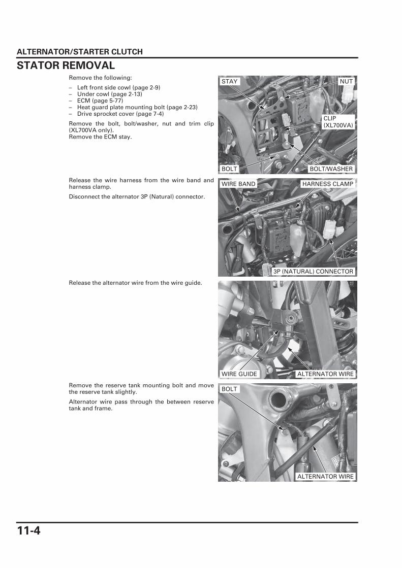
STATOR REMOVALRemove the following:
– Left front side cowl (page 2-9)– Under cowl (page 2-13)– ECM (page 5-77)– Heat guard plate mounting bolt (page 2-23)– Drive sprocket cover (page 7-4)
Remove the bolt, bolt/washer, nut and trim clip(XL700VA only).Remove the ECM stay.
Release the wire harness from the wire band andharness clamp.
Disconnect the alternator 3P (Natural) connector.
Release the alternator wire from the wire guide.
Remove the reserve tank mounting bolt and movethe reserve tank slightly.
Alternator wire pass through the between reservetank and frame.
STAY NUT
CLIP (XL700VA)
BOLT/WASHERBOLT
3P (NATURAL) CONNECTOR
WIRE BAND HARNESS CLAMP
WIRE GUIDE ALTERNATOR WIRE
BOLT
ALTERNATOR WIRE

ALTERNATOR/STARTER CLUTCH
11-5
Loosen the bolts in
a crisscross pattern
in several steps.
Remove the bolts and left crankcase cover.
• The left crankcase cover (stator) is magneticallyattracted to the flywheel, be careful duringremoval.
• Be careful not to damage the alternator covermating surface.
• Engine oil will run out when the alternator coveris removed. Set a oil pan under the engine andadd the recommended oil to the specified levelafter installation.
Be careful not to
damage the mating
surface.
Remove the dowel pins and clean off the sealantfrom the mating surface.
Remove the bolt and stator wire holder from the leftcrankcase cover.
Remove the wire grommet.
Remove the bolts and stator from the left crankcasecover.
LEFT CRANKCASE COVER
BOLTS
DOWEL PINS
BOLT
HOLDER
GROMMET
BOLTS
STATOR

ALTERNATOR/STARTER CLUTCH
11-6
FLYWHEEL/STARTER CLUTCHFLYWHEEL REMOVAL
For alternator
charging coil
inspection (page
17-9).
Remove the left crankcase cover (page 11-4).
Remove the starter reduction gear and shaft.Remove the starter idle gear and shaft.
The flywheel bolt
has left hand
thread.
Remove the flywheel bolt and washer while holdingthe flywheel using the special tool.
Remove the flywheel using the special tool.
Remove the washer and needle bearing and woo-druff key from the crankshaft.
• When woodruff key removal, be careful not todamage the key groove and crankshaft.
• Do not lose the woodruff key.
REDUCTION GEARIDLE GEAR
SHAFTS
TOOL:
Flywheel holder 07725-0040001 or equivalent commer-cially available
BOLT/WAHSER
FLYWHEEL HOLDER
TOOL:
Rotor puller 07733-0020001
ROTOR PULLER
FLYWHEEL
WOODRUFF KEY
NEEDLE BEARING
WASHER

ALTERNATOR/STARTER CLUTCH
11-7
STARTER IDLE/REDUCTION GEAR INSPECTION
STARTER IDLE GEAR/SHAFT
Check the starter idle gear and shaft for wear ordamage.
STARTER REDUCTION GEAR/SHAFT
Check the starter reduction gear and shaft for wearor damage.
STARTER DRIVEN GEAR/STARTER CLUTCH REMOVAL
Check the operation of the one-way clutch by turn-ing the starter driven gear.You should be able to turn the driven gear counter-clockwise smoothly, but the gear should not turnclockwise.
Remove the starter driven gear from the flywheelwhile turning the driven gear counterclockwise.
IDLE GEAR
SHAFT
REDUCTION GEAR
SHAFT
DRIVEN GEAR
FLYWHEEL

ALTERNATOR/STARTER CLUTCH
11-8
Remove the torx bolts while holding the flywheelusing the special tool.
Remove the clutch outer and one-way clutch fromthe flywheel.
STARTER CLUTCH INSPECTION
NEEDLE BEARING
Check the needle bearing for abnormal wear ordamage.
ONE-WAY CLUTCH/CLUTCH OUTER
Check the one-way clutch sprag for abnormal wear,damage or irregular movement.
• Do not remove the one-way clutch from theclutch outer, unless it is necessary to replacewith a new one.
• If the spring is removed from the one-way clutchgroove, replace the one-way clutch assemblywith a new one.
Check the clutch outer for wear or damage.
Measure the clutch outer I.D.
TOOL:
Flywheel holder 07725-0040001 or equivalent commer-cially available
TORX BOLTS
FLYWHEEL
ONE-WAY CLUTCH
CLUTCH OUTER
NEEDLE BEARING
SERVICE LIMIT: 74.46 mm (2.931 in)
ONE-WAY CLUTCH
CLUTCH OUTER

ALTERNATOR/STARTER CLUTCH
11-9
STARTER DRIVEN GEAR
Check the one-way clutch sprag contact surface,teeth and sliding surface for wear or damage.
Measure the driven gear O.D.
Measure the driven gear I.D.
STARTER DRIVEN GEAR/STARTER CLUTCH INSTALLATION
Clean and apply engine oil to the one-way clutchsliding surface.Install the one-way clutch into the clutch outer withits flange side facing the flywheel.
SERVICE LIMIT: 57.73 mm (2.273 in)
SERVICE LIMIT: 37.10 mm (1.461 in)
ONE-WAY CLUTCH
DRIVEN GEAR
CLUTCH OUTER
30 N·m (3.1 kgf·m, 22 lbf·ft)
FLYWHEEL
ONE-WAY CLUTCH
CLUTCH OUTER

ALTERNATOR/STARTER CLUTCH
11-10
Install the clutch outer and one-way clutch to the fly-wheel.
Hold the flywheel using the special tool.
Clean and apply a locking agent to the torx boltthreads (page 1-18).Install and tighten the torx bolts to the specifiedtorque.
Install the starter driven gear to the flywheel whileturning the driven gear counterclockwise.
Recheck the one-way clutch operation (page 11-7).
FLYWHEEL INSTALLATION
Apply engine oil to the needle bearing and install itto the crankshaft.Install the washer to the crankshaft.Wipe any oil off the mating surface of the crankshaftwith flywheel and woodruff key groove.
Install the woodruff key to the key groove of thecrankshaft.
FLYWHEEL
CLUTCH OUTER/ONE-WAY CLUTCH
TOOL:
Flywheel holder 07725-0040001 or equivalent commer-cially available
TORQUE: 30 N·m (3.1 kgf·m, 22 lbf·ft)
TORX BOLTS
DRIVEN GEAR
FLYWHEEL
During woodruff
key installation, be
careful not to
damage the key
groove or
crankshaft.
WOODRUFF KEY
NEEDLE BEARING
WASHER

ALTERNATOR/STARTER CLUTCH
11-11
Wipe any oil off the mating surface of the flywheelwith crankshaft.Install the flywheel to the crankshaft, aligning its keygroove with the woodruff key.
Hold the flywheel using the special tool.
Apply engine oil to the flywheel bolt threads andseating surface.
Install and tighten the flywheel bolt with the washerto the specified torque.
Apply engine oil to the starter reduction gear andstarter idle gear shafts outer surface.Install the starter reduction gear, idle gear andshafts to the left crankcase as an assembly.
Install the starter reduction gear with its "OUT" markfacing out.
Install the stator and left crankcase cover (page 11-12).
FLYWHEEL Align
TOOL:
Flywheel holder 07725-0040001 or equivalent commer-cially available
The flywheel bolt
has left hand
thread.TORQUE: 157 N·m (16.0 kgf·m, 116 lbf·ft)
FLYWHEEL HOLDER
BOLT/WAHSER
REDUCTION GEAR
SHAFTSIDLE GEAR
"OUT" MARK

ALTERNATOR/STARTER CLUTCH
11-12
STATOR INSTALLATION
Install the stator to the left crankcase cover.Clean and apply a locking agent to the bolt threads(page 1-18).Install and tighten the stator bolts to the specifiedtorque.
Install the grommets into the groove in the leftcrankcase cover.
Clean and apply a locking agent to the bolt threads(page 1-18).Install the wire holder to the left crankcase cover.Install and tighten the bolt to the specified torque.
STATOR
LEFT CRANKCASE COVER
WIRE HOLDER
12 N·m (1.2 kgf·m, 9 lbf·ft)
12 N·m (1.2 kgf·m, 9 lbf·ft)
TORQUE: 12 N·m (1.2 kgf·m, 9 lbf·ft)
BOLTS
STATOR
TORQUE: 12 N·m (1.2 kgf·m, 9 lbf·ft)
BOLT
HOLDER
GROMMET

ALTERNATOR/STARTER CLUTCH
11-13
Clean off the sealant from the left crankcase covermating surface.
Apply liquid sealant (Three Bond 1207B or equiva-lent) to the left crankcase cover mating surface.
Install the dowel pins.
The left crankcase
cover (stator) is
magnetically
attracted to the
flywheel, be careful
during installation.
Install the left crankcase cover.
Clean and apply locking agent to the bolt threads asshown.
Install and tighten the left crankcase cover bolts in acrisscross pattern in several steps.
Route the alternator wire between the reserve tankand frame.
Install and tighten the reserve tank mounting bolt.
Do not use an
organic solvent
when wiping off the
excessive sealant.
DOWEL PINS
LEFT CRANKCASE COVER
BOLTS BOLT
BOLT
ALTERNATOR WIRE

ALTERNATOR/STARTER CLUTCH
11-14
Install the alternator wire to the wire guide.
Connect the alternator 3P (Natural) connector.
Install the alternator wire to the wire band and har-ness clamp.
Install the ECM stay and trim clip (XL700VA only).Install and tighten the nut, bolt/washer and boltsecurely.
Install the following:
– Drive sprocket cover (page 7-13)– Heat guard plate mounting bolt (page 2-23)– ECM (page 5-77)– Under cowl (page 2-13)– Left front side cowl (page 2-9)
Check the engine oil level (page 3-12).
WIRE GUIDE ALTERNATOR WIRE
Route the wire
harness properly
(page 1-21).
3P (NATURAL) CONNECTOR
WIRE BAND HARNESS CLAMP
STAY NUT
CLIP (XL700VA)
BOLT/WASHERBOLT