11 2 4 - WEBREVIEW
14
* Corresponding author: V.Prakash, Jawaharlal Nehru Technological University Hyderabad, India, [email protected] T.RamaSubbaReddy, Professor & Head of Electrical and Electronics Engineering, Vignan Institute of Technology and Science, Deshmukhi, Hyderabad, India [email protected] S.TaraKalyani, Professor, EEE at JNTU Hyderabad, India [email protected] P.B.Karandikar Professor in Army Institute of Technology, Pune, India [email protected] Copyright © JES 2015 on-line : journal/esrgroups.org/jes Vodapalli Prakash 1 , T.RamaSubbaReddy 2 , S.TaraKalyani 3 , P.B. Karandikar 4 J. Electrical Systems 11-2 (2015): 160-173 Regular paper Comparative Performance of Supercapacitor and Fuel cell based UPQC JES Journal of Journal of Journal of Journal of Electrical Electrical Electrical Electrical Systems Systems Systems Systems In this paper analysis comparative result of a supercapacitor based unified power quality conditioner comparing with a fuel cell based unified power quality conditioner. This work describes the unified power quality conditioner principles and power restoration for balanced or unbalanced voltage sag or swells in a distribution system. This method proposes a typical configuration of unified power quality conditioner that consists of a DC/DC converter supplied by a supercapacitor at the DC link. This analysis used for comparing how the THD will be improved and after injecting current and voltage to UPQC source current and source voltage are sinusoidal. This paper explains the comparative results of UPQC showing performance wise THD of supercapacitor and fuel cell, the harmonic distortion is reduced in fuel cell as compared to supercapacitor. The comparative studies analyse in both the cases fuel cell is better than supercapacitor in power quality parameters as THD and power factor etc. The result analysis shows the THD of supercapacitor and fuel cell, the harmonic distortion is quite reduced in fuel cell as compared to supercapacitor. The operation of the proposed system is modeled and simulated in MATLAB environment using Simulink and Simpower System toolboxes. Keywords: Fuel cell, power quality, supercapacitor, unified power quality conditioner. Article history: Received 21 July 2014, Received in revised form 17 September 2014, Accepted 30 April 2015 1. Introduction The power quality problem is also due to the different faults conditions occurring on the power system network. These conditions cause voltage sag or swell in the system and malfunctioning of devices. The mitigation of these on the source and load sides is most important for improving the reliability as well as performance on the system. The Unified Power Quality Conditioner (UPQC) has a single topology that combines dynamic voltage restorer and distribution static compensator with a common DC link. These two are connected in a back to back configuration. Shunt active power filter compensates all current related distortions and series active power filter compensates all voltage related distortions. The compensation can be done effectively, if there is an effective DC link. The shunt compensator takes care of reactive power compensation, current harmonic compensation, load unbalance compensation and power factor improvement [1]. The series compensator acts for voltage harmonics, voltage sag or swells, flickering etc. with the harmonic isolation between load and supply [2]. The Supercapacitor Energy is used as a battery storage device across the DC link for short time duration. The energy can be stored in the form of batteries, flywheels, compressed air, hydraulic systems and super conducting energy storage systems [3]. A configuration with distribution static compensator - supercapacitor energy storage system is used to enhance
Transcript of 11 2 4 - WEBREVIEW

*Corresponding author: V.Prakash, Jawaharlal Nehru Technological University Hyderabad, India,
[email protected] T.RamaSubbaReddy, Professor & Head of Electrical and Electronics Engineering, Vignan Institute of
Technology and Science, Deshmukhi, Hyderabad, India [email protected]
S.TaraKalyani, Professor, EEE at JNTU Hyderabad, India [email protected]
P.B.Karandikar Professor in Army Institute of Technology, Pune, India [email protected]
Copyright © JES 2015 on-line : journal/esrgroups.org/jes
Vodapalli Prakash1,
T.RamaSubbaReddy2,
S.TaraKalyani3,
P.B. Karandikar4
J. Electrical Systems 11-2 (2015): 160-173
Regular paper
Comparative Performance of
Supercapacitor and Fuel cell based
UPQC
JES
Journal of Journal of Journal of Journal of Electrical Electrical Electrical Electrical SystemsSystemsSystemsSystems
In this paper analysis comparative result of a supercapacitor based unified power quality conditioner comparing with a fuel cell based unified power quality conditioner. This work describes the unified power quality conditioner principles and power restoration for balanced or unbalanced voltage sag or swells in a distribution system. This method proposes a typical configuration of unified power quality conditioner that consists of a DC/DC converter supplied by a supercapacitor at the DC link. This analysis used for comparing how the THD will be improved and after injecting current and voltage to UPQC source current and source voltage are sinusoidal. This paper explains the comparative results of UPQC showing performance wise THD of supercapacitor and fuel cell, the harmonic distortion is reduced in fuel cell as compared to supercapacitor. The comparative studies analyse in both the cases fuel cell is better than supercapacitor in power quality parameters as THD and power factor etc. The result analysis shows the THD of supercapacitor and fuel cell, the harmonic distortion is quite reduced in fuel cell as compared to supercapacitor. The operation of the proposed system is modeled and simulated in MATLAB environment using Simulink and Simpower System toolboxes.
Keywords: Fuel cell, power quality, supercapacitor, unified power quality conditioner. Article history: Received 21 July 2014, Received in revised form 17 September 2014, Accepted 30 April 2015
1. Introduction
The power quality problem is also due to the different faults conditions occurring on the
power system network. These conditions cause voltage sag or swell in the system and
malfunctioning of devices. The mitigation of these on the source and load sides is most
important for improving the reliability as well as performance on the system. The Unified
Power Quality Conditioner (UPQC) has a single topology that combines dynamic voltage
restorer and distribution static compensator with a common DC link. These two are
connected in a back to back configuration. Shunt active power filter compensates all current
related distortions and series active power filter compensates all voltage related distortions.
The compensation can be done effectively, if there is an effective DC link. The shunt
compensator takes care of reactive power compensation, current harmonic compensation,
load unbalance compensation and power factor improvement [1]. The series compensator
acts for voltage harmonics, voltage sag or swells, flickering etc. with the harmonic isolation
between load and supply [2]. The Supercapacitor Energy is used as a battery storage device
across the DC link for short time duration.
The energy can be stored in the form of batteries, flywheels, compressed air,
hydraulic systems and super conducting energy storage systems [3]. A configuration with
distribution static compensator - supercapacitor energy storage system is used to enhance

V. Prakash et al: Comparative Performance of Supercapacitor and Fuel cell based UPQC
161
power system stability and quality [4]. Supercapacitors are also find applications in
industrial drives such as traction [5], metro vehicles and hybrid electric vehicles [6]. The
operation of both series active power filter and shunt active power filter are based on
voltage source converter technique. The shunt active filter compensates the voltage
interruption if it has the some energy storage or battery in the DC link [7]. The battery has a
high storage capacity but unreliable and flywheels requires a lot of maintenance. The
discharge rate is slower in batteries because of slower chemical process. As the future
turned to higher rate of charging and discharging the energy which is possible with the
supercapacitors. The supercapacitors stores less energy however, the power transfer
capability is high compared to the conventional batteries. The rate of discharge of
supercapacitor while compensation is fast and it takes only a small current for charging [3].
Use of supercapacitor is proposed in UPQC scheme as it is characterized by less weight,
faster charge/discharge cycle time, higher power density, higher efficiency and almost
maintenance free.
In paper [8] described the application of full bridge DC-DC converters in UPQC. Papers
[9,10] and [11] concentrated only on voltage sag or swell utilizing the series inverter.
UPQC can be utilized to solve power quality problems simultaneously [12,13] and [14].
The most important parameters and materials [15,16] and manufacturing process of a
supercapacitor [17,18] and [19] include the capacitance(C), equivalent series resistance and
equivalent parallel resistance which is also called leakage resistance [20]. Ultracapacitors
having high power density can be used to complement the high energy density batteries to
form an excellent hybrid energy storage system [19]. This paper suggests a new form of
UPQC, DC/DC converter, fuel cell and energy storage system. A fuel cell is a device that
directly converts the chemical energy of fuel to electric energy. Fuel cells are also used as
power sources such as cars, trucks, buses, submarines and batteries for electronics such as
laptops and smart phones as well as sources for uninterruptable power supplies. The
operation of the proposed system is modeled and simulated in MATLAB environment
using Simulink and Simpower System toolboxes. This paper is organized as: Section 2;
describes the notations used throughout the paper, Section 3; describes the supercapacitor
based UPQC, explains about schemes of series and shunt converters and supercapacitors.
Section 4; deals with the description of the fuel cell based UPQC includes equivalent circuit
diagram of fuel cell and principles. Section 5; presents the comparative study of UPQC
based on supercapacitor and fuel cell. Section 6; presents the conclusion. Sections 7;
presents the appendix.
2. Notation
The notations used throughout the paper listed below.
VL - Load voltage
Vs - Source voltage
IL - Load Current
Is - Source Current
RL - Load Resistance LL - Load Inductance

J. Electrical Systems 11-2 (2015): 160-173
162
Cdc - DC Link Capacitance Vdc - DC Link Voltage Rs - Source Resistance Ls - Source Inductance Lsh - Shunt Inductance Lse - Series Inductance if - Leakage current (A)
Vinj - Injected Voltage
Iinj- Injected Current Iref - Reference Current Vin - input voltage Vcs - Voltage across stack capacitance Vcr - Voltage across reformer capacitance
Rst - Stack resistance
Rrf -Reformer Resistance
rτ - Reformer time constant
sτ - stack time constant
THD - third harmonic distortion Ubank_min - Minimum voltage across the bank
Ubank_max - Maximum voltage across the bank
Ns - No. of series supercapacitors required
Np - No. of parallel supercapacitors required
α - Charge transfer coefficient, Tafel equation (0<alpha<1)
∆V - Over potential
3. Supercapacitor based UPQC
The block diagram representation for the proposed system is shown in Fig.1 Single phase
UPQC connected to a power system feeding a combination of linear and non-linear loads. It
consists of a two leg voltage controlled voltage source inverter used as a series active power
filter and a two leg current controlled voltage source inverter used as a shunt active power
filter. The DC link of both of these active filters is connected to a common DC link
capacitor. Also capable of suppressing the harmonics in the source currents, load balancing
and power factor correction. The series filter is connected between the supply and load
terminals using a single phase transformer. The main aim of the series active power filter is
to obtain harmonic isolation between the load and supply.

V. Prakash et al: Comparative Performance of Supercapacitor and Fuel cell based UPQC
163
Fig.1 Block Diagram of the Proposed System
.
The voltage source inverters for both the series and shunt active power filters are
implemented with IGBTs. The supercapacitor bank consists of number of series and
parallel capacitors to increase the current as well as voltage at the DC link and the DC/DC
converter is used to maintain constant voltage at the DC link irrespective of the voltage at
the supercapacitor bank. It boosts the voltage level when sag appears in the line and
consumes energy when there is a swell in the line. The voltage sag or swell can be
effectively compensated using a dynamic voltage restorer, series active filter, UPQC, etc.
The performance of a single-phase unified power quality conditioner is evaluated for the
mitigation of customer-generated harmonics, total current harmonics, reactive power,
voltage harmonics, and their combinations, depending on the requirements [21]. The series
active power filter takes care about voltage related issues [22]. The shunt active power filter
is used to absorb current harmonics to compensate for reactive power and to regulate the
DC link voltage between both active power filters. The unified power quality conditioner
has the capability of voltage imbalance compensation as well as voltage regulation and
harmonic compensation at the consumer end [23, 24] and [25-26]. In this paper, the
proposed synchronous reference frame based control method for the UPQC system with a
DC/DC converter to control voltage at the supercapacitor end is used and the system
performance is improved. In the proposed control method, load voltage, source voltage,
source current are measured, evaluated also tested under unbalanced and distorted load
conditions using MATLAB/Simulink software. The values of the circuit parameters and the
loads under consideration in such a way that to compensate the problem are given in the
appendix [27].
J. Electrical Systems 11-2 (2015): 160-173
164
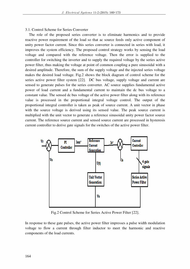
3.1. Control Scheme for Series Converter
The role of the proposed series converter is to eliminate harmonics and to provide
reactive power requirement of the load so that ac source feeds only active component of
unity power factor current. Since this series converter is connected in series with load, it
improves the system efficiency. The proposed control strategy works by sensing the load
voltage and compared with the reference voltage. Then the error is supplied to the
controller for switching the inverter and to supply the required voltage by the series active
power filter, thus making the voltage at point of common coupling a pure sinusoidal with a
desired amplitude. Therefore, the sum of the supply voltage and the injected series voltage
makes the desired load voltage. Fig.2 shows the block diagram of control scheme for the
series active power filter system [22]. DC bus voltage, supply voltage and current are
sensed to generate pulses for the series converter. AC source supplies fundamental active
power of load current and a fundamental current to maintain the dc bus voltage to a
constant value. The sensed dc bus voltage of the active power filter along with its reference
value is processed in the proportional integral voltage control. The output of the
proportional integral controller is taken as peak of source current. A unit vector in phase
with the source voltage is derived using its sensed value. The peak source current is
multiplied with the unit vector to generate a reference sinusoidal unity power factor source
current. The reference source current and sensed source current are processed in hysteresis
current controller to derive gate signals for the switches of the active power filter.
Fig.2 Control Scheme for Series Active Power Filter [22].
In response to these gate pulses, the active power filter impresses a pulse width modulation
voltage to flow a current through filter inductor to meet the harmonic and reactive
components of the load currents.

V. Prakash et al: Comparative Performance of Supercapacitor and Fuel cell based UPQC
165
a. Control Scheme for Shunt Converter
The shunt active filter is a current controlled voltage source inverter, which is
connected in parallel with the load. Hence, the utility needs to supply only the active part of
the fundamental component of the load current. Control algorithm computes the reference
for the compensation current to be injected by the shunt active filter. In the proposed
control algorithm the sensed currents are compared with the reference currents in a
hysteresis current controller to generate switching pulses for the shunt active power filter.
The choice of the control algorithm therefore decides the accuracy and response time of the
filter. The control strategy has an objective to guarantee balanced and sinusoidal source
current at unity power factor. The hysteresis current control scheme decides the switching
pattern of active filter in such a way to maintain the actual injected current of the filter to
remain within a desired hysteresis band.
The switching logic is formulated as follows:
If iinj< (iref − HB) S1, S2 ON & S3, S4 OFF
If iinj> (iref + HB) S1, S2 OFF & S3, S4 ON
The switching frequency of the hysteresis current control method described above depends
on how fast the current changes from upper limit to lower limit of the hysteresis band, or
vice versa. Therefore the switching frequency does not remain constant throughout the
switching operation, but varies along with the current waveform. Furthermore, the filter
inductance value of the active filter is the main parameter determining the rate of change of
active filter current.
3.2. Supercapacitor Energy Storage Systems
Usually supercapacitors are divided into two types: double-layer capacitors and
electrochemical capacitors. Its capacitance is proportional to the specific surface areas of
electrode material. The capacitors can work at high voltage without connecting many cells
in series. The size of supercapacitor is determined from the size of load connected and the
duration of voltage interruption. Therefore, total energy to be released during the voltage
interruption is 30kJ. The maximum current flows through the supercapacitor bank, when it
discharges the maximum power. The minimum voltage across the supercapacitor bank can
be determined with the maximum discharge power and the current rating as the following
[28].
(1) 55.5V = =_min Ubank 360
20
A
kw
The lowest discharged voltage is determined to be 2.1V using the following [28].
(2) 2.1V =_max Uunit =_min Uunit 4
3
Therefore, the lowest discharge voltage and the minimum unit voltage determine the
number of units to be connected in series as the following [28].

J. Electrical Systems
166
= Uunit_min
min _Ubank = Ns
By using (2) and (3), bank design calculation can be determined as 28 units of
supercapacitors.
Fig.3.Simulink Block Diagram for the Proposed System using supercapacitor
Electrical Systems 11-2 (2015): 160-173
(3) 26.5 =2.1
55.5=
Uunit_min
min
By using (2) and (3), bank design calculation can be determined as 28 units of
Simulink Block Diagram for the Proposed System using supercapacitor.

V. Prakash et al: Comparative Performance of Supercapacitor and Fuel cell based UPQC
3.3. DC-DC Converter
The proposed DC/DC converter can operate in bi
of the supercapacitor bank is in the range between 60
about 700V. The converter should have high current rating at the bank side and
voltage rating at the DC link side. The DC/DC converter boosts the supercapacitor voltage
up to the nominal DC link voltage in discharge mode. The supercapacitor voltage is
controlled between 60-75V, while the DC link voltage increases up to 700V
4. Fuel Cell based UPQC
The fuel cell generation system which is considered of a reformer and a stack t
generates electricity using electrochemical reaction.
Fig.4 Equivalent circuit of a Fuel Cell System [2
Fig.4 shows equivalent circuit of a fuel cell system [2
reformer produces usually hydrogen from fuels and then supplies it to the stacks. The stacks
generate DC electric power by electrochemical reaction of hydrogen a
in the air [29], [30-31]. The reformer is represented as a first order time delay circuit which
has relatively long time constant for an electrical equivalent circuit. The stack is a
collection of unit cells and the unit cells consist of ele
cell output is the result of a chemical reaction and possesses nonlinear characteristics.
mathematical model [32] of the reformer and
(5).
The stack is also represented as a first order time delay circuit which has a relatively short
time constant. The mathematical model of the reformer and stack are represented as
11
1=
CrS
1Rr
CrS
1
= Vin
Vcr
RrCrS=
++
1
1=
CsS
1Rr
CsS
1
= Vcr
Vcs
RsCsS++
Where rτ = RrCr is the time constant of the reformer
sτ = RsCs is the time constant of the stack
Comparative Performance of Supercapacitor and Fuel cell based UPQC
167
The proposed DC/DC converter can operate in bi-directional mode. The operation voltage
of the supercapacitor bank is in the range between 60-75V, while the DC link voltage is
about 700V. The converter should have high current rating at the bank side and high
voltage rating at the DC link side. The DC/DC converter boosts the supercapacitor voltage
up to the nominal DC link voltage in discharge mode. The supercapacitor voltage is
75V, while the DC link voltage increases up to 700V.
The fuel cell generation system which is considered of a reformer and a stack that
electrochemical reaction.
circuit of a Fuel Cell System [28]
shows equivalent circuit of a fuel cell system [28]. It contains reformer and stack, the
reformer produces usually hydrogen from fuels and then supplies it to the stacks. The stacks
generate DC electric power by electrochemical reaction of hydrogen and oxygen which is
]. The reformer is represented as a first order time delay circuit which
has relatively long time constant for an electrical equivalent circuit. The stack is a
collection of unit cells and the unit cells consist of electrolyte, separators and plates. Fuel
cell output is the result of a chemical reaction and possesses nonlinear characteristics. The
] of the reformer and- stack are represented by equations (4) and
as a first order time delay circuit which has a relatively short
The mathematical model of the reformer and stack are represented as
(4) 1
1
rSτ+
(5) 1
1
sSτ+
=
is the time constant of the reformer
the time constant of the stack, In general rτ > sτ .

J. Electrical Systems
168
Fig.5 Combined operation of UPQC and Fuel Cell [32
Fig.5 shows the operation of UPQC and Fuel
two voltage-source inverters in three
configuration. One inverter called the series inverter is connected through transformers
between the source and the common connection p
inverter is connected in parallel with the common connection point through transformers.
The series inverter operates as a voltage source, while the shunt inverter operates as a
current source. UPQC has compensati
power compensation, voltage disturbances, and the power
Fig.6 shows the waveforms of Vinj,Inj before
Fig.6
Electrical Systems 11-2 (2015): 160-173
ration of UPQC and Fuel Cell [32]
PQC and Fuel Cell combinedly [32], normally UPQC has
source inverters in three-phase four-wire or three-phase three-wire
configuration. One inverter called the series inverter is connected through transformers
between the source and the common connection point. The other inverter called the shunt
inverter is connected in parallel with the common connection point through transformers.
The series inverter operates as a voltage source, while the shunt inverter operates as a
UPQC has compensation capabilities for the harmonic current, reactive
power compensation, voltage disturbances, and the power-flow control.
before injecting [31].
Fig.6 before injecting

V. Prakash et al: Comparative Performance of Supercapacitor and Fuel cell based UPQC
169
5. Comparative Study of Supercapacitor and Fuel cell based UPQC.
FFT ANALYSIS
Fig.7 With supercapacitor
J. Electrical Systems
170
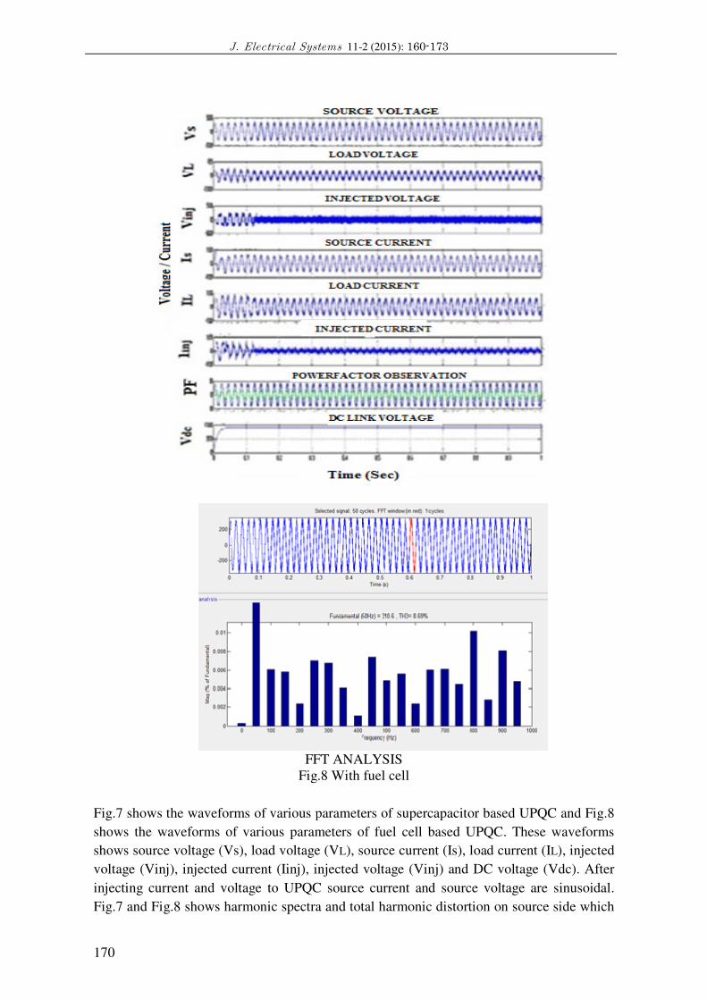
FFT ANALYSIS
Fig.8
Fig.7 shows the waveforms of various parameters of supercapacitor based UPQC and Fig.
shows the waveforms of various parameters of fuel cell based UPQC. These waveforms
shows source voltage (Vs), load voltage (V
voltage (Vinj), injected current (Iinj), injected volt
injecting current and voltage to UPQC source current and source voltage are sinusoidal.
Fig.7 and Fig.8 shows harmonic spectra and total harmonic distortion o
Electrical Systems 11-2 (2015): 160-173
FFT ANALYSIS
Fig.8 With fuel cell
shows the waveforms of various parameters of supercapacitor based UPQC and Fig.8
shows the waveforms of various parameters of fuel cell based UPQC. These waveforms
shows source voltage (Vs), load voltage (VL), source current (Is), load current (IL), injected
voltage (Vinj), injected current (Iinj), injected voltage (Vinj) and DC voltage (Vdc). After
injecting current and voltage to UPQC source current and source voltage are sinusoidal.
shows harmonic spectra and total harmonic distortion on source side which

V. Prakash et al: Comparative Performance of Supercapacitor and Fuel cell based UPQC
171
is of 0.31%. The FFT analysis shows the THD of supercapacitor and fuel cell, the
harmonic distortion is quite reduced in fuel cell as compared to supercapacitor as shown in
FFT analysis, as the number of cycles depends upon the cycles comparing with fuel cell
less in supercapacitor. The source current (Is) becomes sinusoidal and in phase with the
source voltage (Vs). The THD of the source current has been improved comparing with
supercapacitor to 0.09%. The DC link voltage of the back to back connected VSI is
maintained to the reference value. TABLE I explains the analysis comparative results of a
UPQC with supercapacitor and fuel cell.
TABLE I: PERFORMANCE OF UPQC WITH SUPERCAPACITOR AND FUEL CELL
6. Conclusion
The paper describes the analysis comparative results of a supercapacitor based unified
power quality conditioner comparing with a fuel cell based unified power quality
conditioner. Out of the custom power devices UPQC is the most effective device for
mitigating the power quality problems. The performance of the proposed system consists of
a DC/DC converter, supercapacitors and a fuel cell connected through DC line. The
proposed system can compensated voltage sag and swells with improved power factor,
voltage interruption and harmonics. The proposed UPQC has the ultimate capability of
improving the power quality at the installation point in the distribution system.
7. Appendix
The operation of the system was demonstrated through simulation with
MATLAB/SIMULINK software byusing the circuit parameters and the loads under
consideration as follows:
Vs = 230V, f = 50Hz, Rl = 10, Ll = 25mH, Cdc = 4700uF, Vdc = 700V, Rs = 0.01, Ls =
50uH, Lsh = 8mH, Lse = 2.5mH.
Super Capacitor Ratings: Crated = 1000F, Rse = 2.1mohms, Vrated = 65V, Surge Voltage
= 75V, N = 28, Np = 1, Initial Voltage = 60V, (if) leakage Current = 5.2mA, Temperature =
25 C.
Stern-Tafel Parameters:
N = 6, r = 1.23*10-9
,∆V = 0.3V, α = 0.3, Charge Current=100A.
Control Method Parameter
Magnitude Voltage
& Current per phase
(Vrms & Irms)
%THD
UPQC
With
Supercapacitor
Source Voltage (V) (VSabc_rms) 220V 2.51%
Load Voltage (V) (VLabc_rms) 219.23 V 0.58%
Source Current (A) (iSabc_rms) 12.13 A 3.10%
Load Current (A) (iLabc_rms) 12.31 A 29.35%
UPQC
with
Fuel Cell
Source Voltage (V) (VSabc_rms) 220V 1.05%
Load Voltage (V) (VLabc_rms) 219.23 V 0.31%
Source Current (A) ( iSabc_rms) 12.13 A 1.66%
Load Current (A) ( iLabc_rms) 12.31 A 21.15%

J. Electrical Systems 11-2 (2015): 160-173
172
References [1] F.Mekri, M.A. Machmoum,,N.A. Mazari, B,Iren, “Afuzzy hysteresis voltage and current control of an unified
power quality conditioner”, Industrial Electronics,IECON 34th Annual Conference of IEEE, 2008, 2684-2689.
[2] V.Khadkikar, A.Chandra “A new control philosophy for a unified power quality conditioner (UPQC) to
coordinate load – reactive power demand between shunt and series inverters,” IEEE Transactions on Power
Delivery,23,2008,2522-2534.
[3] S. C. Smith, and P. K. Sen, B. Kroposki, "Advancement of energy storage devices and applications in electrical
power system", IEEE Power and Energy Society General Meeting - Conversion and Delivery of Electrical Energy
in the 21st Century, 2008, pp.1-8.
[4] P. Srithorn, M. Sumner, and L. Yao, R. Parashar, "A STATCOM with Super-Capacitors for enhanced power
system stability" 4th IET Conference on Power Electronics, Machines and Drives , 2008 , pp.96-100.
[5] W. Lhomme, P. Delarue, P. Barrade, A. Bouscayrol, A. Rufer, " Design and Control of a Supercapacitor
Design Storage System for Traction Applications”, Industry applications conference, 2005.
[6] Z. Y-cheng; W. Lu-lu, Z. Xue-jun, and L. Hai-quan, "Design of Super-Capacitor-based Energy Storage System
for Metro Vehicles and Its Control Rapid Implementation" IEEE Vehicle Power and Propulsion Conference,
Harbin, 2008.
[7] H. Akagi, E. H. Watanabe, and M. Aredes,Instantaneous Power Theory and Applications to Power
Conditioning. Hoboken, NJ: Wiley-IEEE Press, Apr. 2007.
[8] Yang Zhang, Shengfa Zhang, Jiahong Chen “The Applications of Bidirectional Full-bridge DC-DC Isolated
Converter in UPQC”, Electrical Machines and Systems, 2008. ICEMS 2008, Wuhan, Oct. 2008, pp1916 – 1921.
[9] Malabika Basu S. P. Das Gopal K. Dubey “Performance Study of UPQC-Q for Load Compensation and
Voltage Sag Mitigation”IEEE Conf.2002.
[10]MaurícioAredes and Rodrigo M. Fernandes “A Unified power quality conditioner with voltage sag/swell
Compensation capability.IEEE conf. 2009.
[11]VinodKhadkikar, Member, IEEE, and Ambrish Chandra, Senior Member, IEEE “UPQC-S: A Novel Concept
of Simultaneous Voltage Sag/Swell and Load Reactive Power Compensations Utilizing Series Inverter of UPQC”
IEEE transactions on power electronics, vol. 26, no. 9, september 2011.
[12] V. Khadkikar and A. Chandra, “A new control philosophy for a unified power quality conditioner (UPQC) to
coordinate load-reactive power demand between shunt and series inverters,” IEEE Trans. Power Del., vol. 23, no.
4, pp. 2522–2534, Oct. 2008.
[13] B. Han, B. Bae, H. Kim, and S. Baek, “Combined operation of unified power-quality conditioner with
distributed generation,” IEEE Trans.Power Del., vol. 21, no. 1, pp. 330–338, Jan. 2006.
[14] B. Singh, K. Al-Haddad, and A. Chandra, “A review of active power filters for power quality improvement,”
IEEE Trans. Ind. Electron., vol. 45, no. 5, pp. 960–971, Oct. 1999.
[15] P.B.Karandikar, D.B.Talange, UdayMhaskar, Ramesh Bansal, “Development, characterization and
modelling of aqueous metal oxide based Super-Capacitor”, Energy, Elsevier, April 2012, Vol 40, pp 131-138.
[16] P.B.Karandikar, D.B.Talange, UdayMhaskar, Ramesh Bansal, Materials and manufacturing processes,
“Investigations in to material and manufacturing aspects of aqueous Super-Capacitor”, Taylor and Francis,
November 2012, 27 (11), pg. 1164-1170 .
[17] P B Karandikar, D B Talange, “Method of manufacturing electrode for Super-Capacitor”, 2858/MUM/2010,
Filed on 2010-10-14, Publication date 2011-01-07.
[18] Sandwich type Supercapacitormaking process, P B Karandikar, D B Talange, A. Dekate, Atul Singh, N S
Prasun, 841/MU1M/2011Filed on 2011-03-23, Publication date 2011-09-16.
[19] P B Karandikar, D B Talange, Amit Singh, Raju Pal, Gary Singh, AnshumanSarkar, “Regenerative braking in
electric two wheeler using Super-Capacitors”,843/MUM/2011, Filed on 2011-03-23, Publication date 2011-09-16.
[20] P.B.Karandikar, D.B.Talange, UdayMhaskar, Ramesh Bansal, ‘Validation of Capacitance and ESR Model of
Manganese Oxide Based Aqueous Super-Capacitor”, Electric Power Components and Systems, Taylor and
Francis, vol. 40, no. 10, pp. 1105-1118, 2012.
[21] SumitKumar,H. P. Ikkurti Electric Power Components and Systems “Power Electronic Interface for Energy
Management in Battery Ultracapacitor Hybrid Energy Storage System” Taylor and Francis, 2013 Vol. 41, Issue
11, pg. 1059-1074.
[22] Yash Pal, A. Swarup&Bhim Singh “Flexible Control of Single-phase Unified Power Quality Conditioner
Using Frequency-domain Approach,Taylor and Francis, 2012, pg 401-412.

V. Prakash et al: Comparative Performance of Supercapacitor and Fuel cell based UPQC
173
[23] RishikaParihar, Deepti Sharma and PayalSuhane “Resonant Converter With Universal Active Power Filter
(Pwm) In Single Phase Applications”, International Journal of Software & Hardware Research in Engineering,
ISSN No: 2347-4890 Volume 2 Issue 4, April 2014.
[24] M. El-Habrouk, M. K. Darwish, and P. Mehta, “Active power filters: A review,” IEE Electr. Power Appl.,
vol. 147, no. 5, pp. 403–413, Sep. 2000.
[25] C. N. Ho and H. S. Chung, “Implementation and performance evaluation of a fast dynamic control scheme for
capacitor-supported interline DVR,” IEEE Trans. Power Electron., vol. 25, no. 8, pp. 1975–1988, Aug. 2010.
[26] Doncker, C. Meyer, R. W. De, W. L. Yun, and F. Blaabjerg, “Optimized control strategy for a medium-
voltage DVR—Theoretical investigations and experimental results,” IEEE Trans. Power Electron., vol. 23, no. 6,
pp. 2746–2754, Nov. 2008.
[27] Bhim Singh, Senior Member, IEEE, P. Jayaprakash, Student Member, IEEE, and D. P. Kothari, Senior
Member, IEEE “A T-Connected Transformer and Three-leg VSC Based DSTATCOM for Power Quality
Improvement” IEEE TRANSACTIONS ON POWER ELECTRONICS, VOL. 23, NO. 6, NOVEMBER 2008.
[28] The MathworksInc, MATLAB R2013a and Simulink are registered trademarks of Mathworks, Inc.
[29] Y. Kim, S. Kim, " An Electrical modeling and Fuzzy Logic Control of a Fuel Cell Generation System", IEEE
Transactions on Energy Conversion, Vol. 14, No. 22, pp. 239-244, June,1999.
[30] J. Jung, M. Dai, A. Keyhani, "Modeling and Control of a Fuel Cell Based Z-Source Converter," IEEE
Applied Power Electronics Conference and Exposition, APEC'05, Vol. 2, pp. 1112-1118, March 6-10, 2005,
Austin, TX.
[31] Mahmoodi, M. Gharehpetian, G.B. Abedi, M.Noroozian, R ,”Novel and Simple Control Strategy for Fuel
Cell Converters in DC Distribution Systems”,”PowerandEnergy Conference, PECon '06. IEEE International”
Nov.2006 pp. 358-362.
[32] M.Ale-Emran, M. Forghani, M.Abedi ,G.B.Gharehpetian “Combined Operation of UPQC and Fuel Cell with
Common DC Bus”, ‘http://www.icrepq.com/icrepq-08/468-ale-emran.pdf’.


![[WEBREVIEW]€¦ · (10) paperless society PRESTEL CEEFAX ANTIOPE - curriculum Development 1992 — 2 — MEDLINE a; .39 (7 (8 .44 (9 10) Lancaster «the paperless society» Chicago](https://static.fdocuments.in/doc/165x107/60339a70e83b5145ff04a46b/webreview-10-paperless-society-prestel-ceefax-antiope-curriculum-development.jpg)