10W Adaptor Module Using UPSR1103 - Unisonic€¦ · 1.4. Protection Function 3 ... A dynamic...
18
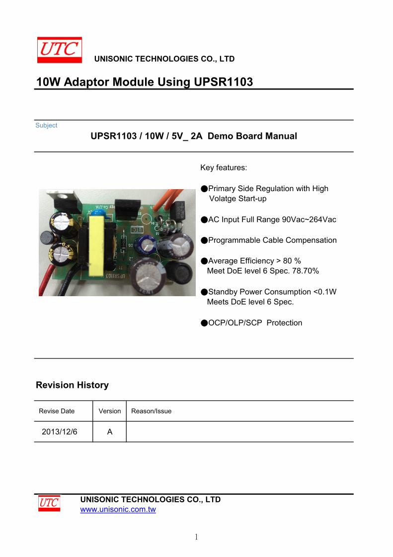
UNISONIC TECHNOLOGIES CO., LTD 10W Adaptor Module Using UPSR1103 Subject Key features: ●Primary Side Regulation with High Volatge Start-up ●AC Input Full Range 90Vac~264Vac ●Programmable Cable Compensation ●Average Efficiency > 80 % Meet DoE level 6 Spec. 78.70% ●Standby Power Consumption <0.1W Meets DoE level 6 Spec. ●OCP/OLP/SCP Protection Revision History Revise Date Version Reason/Issue 2013/12/6 A UNISONIC TECHNOLOGIES CO., LTD www.unisonic.com.tw UPSR1103 / 10W / 5V_ 2A Demo Board Manual 1
Transcript of 10W Adaptor Module Using UPSR1103 - Unisonic€¦ · 1.4. Protection Function 3 ... A dynamic...
UNISONIC TECHNOLOGIES CO., LTD
10W Adaptor Module Using UPSR1103
Subject
Key features:
●Primary Side Regulation with High Volatge Start-up
●AC Input Full Range 90Vac~264Vac
●Programmable Cable Compensation
●Average Efficiency > 80 % Meet DoE level 6 Spec. 78.70%
●Standby Power Consumption <0.1W Meets DoE level 6 Spec.
●OCP/OLP/SCP Protection
Revision History
Revise Date Version Reason/Issue
2013/12/6 A
UNISONIC TECHNOLOGIES CO., LTDwww.unisonic.com.tw
UPSR1103 / 10W / 5V_ 2A Demo Board Manual
1
10W Adaptor Module Using UPSR1103
Contents Index Page
1 Adaptor Module Specification 31.1 Input Characteristics 31.2 Output Characteristics 31.3 Performance Specifications 31.4. Protection Function 31.5 Environment 3
2 Adaptor Module Information 42.1 Schematic 42.2 BOM 42.3 Adaptor Module Snapshot 52.4 Transformer Design 62.4.1 Transformer Specification 62.4.2 Transformer Winding Data 6
3 Performance Evaluation 73.1 Input Characteristics 83.1.1 Input Current and Standby Power 83.1.2 Efficiency 83.2 Output Characteristics 83.2.1 Line Regulation & Load Regulation 83.2.2 IV-Curve 93.2.3 Cable Compensation 103.2.4 Ripple & Noise 113.2.5 Overshoot & Undershoot 123.2.6 Dynamic Test 133.2.7 Time Sequence 133.3 Protection 153.3.1 Short Circuit Protection 153.3.2 Open Loop Protection 153.3.3 Over Load Protection 153.3.4 Thermal Testing 16
4 Other Important Waveforms 174.1 Vds, Vcc, Vcs& Vs Waveform at No Load/Full Load 174.2 Vds& Vf Waveform at Full Load, Start / Normal / Output Short 174.2.1 Vds& Vf at Full Load, Start / Normal / Output Short 174.2.2 Vds& Vf at full load, start waveform 184.2.3 Vds& Vf at full load, normal waveform 184.2.4 Vds& Vf at full load, output short waveform 18
UNISONIC TECHNOLOGIES CO., LTD www.unisonic.com.tw
2
10W Adaptor Module Using UPSR1103
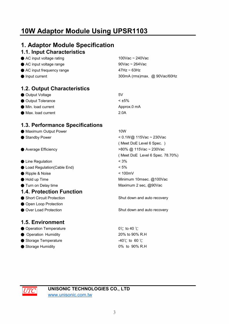
1. Adaptor Module Specification1.1. Input Characteristics● AC input voltage rating 100Vac ~ 240Vac● AC input voltage range 90Vac ~ 264Vac● AC input frequency range 47Hz ~ 63Hz● Input current 300mA (rms)max. @ 90Vac/60Hz
1.2. Output Characteristics● Output Voltage 5V● Output Tolerance < ±5%● Min. load current Approx.0 mA● Max. load current 2.0A
1.3. Performance Specifications● Maximum Output Power 10W● Standby Power < 0.1W@ 115Vac ~ 230Vac
( Meet DoE Level 6 Spec. )● Average Efficiency >80% @ 115Vac ~ 230Vac
( Meet DoE Level 6 Spec. 78.70%)● Line Regulation < 3%● Load Regulation(Cable End) < 5%● Ripple & Noise < 100mV● Hold up Time Minimum 10msec. @100Vac● Turn on Delay time Maximum 2 sec, @90Vac
1.4. Protection Function● Short Circuit Protection Shut down and auto recovery● Open Loop Protection● Over Load Protection Shut down and auto recovery
1.5. Environment● Operation Temperature 0℃ to 40 ℃● Operation Humidity 20% to 90% R.H● Storage Temperature -40℃ to 60 ℃● Storage Humidity 0% to 90% R.H
UNISONIC TECHNOLOGIES CO., LTD www.unisonic.com.tw
3
10W Adaptor Module Using UPSR1103
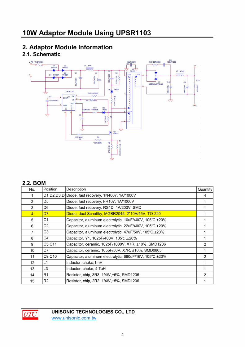
2. Adaptor Module Information2.1. Schematic
2.2. BOMNo. Quantity1 42 13 14 15 16 17 18 19 210 111 212 113 114 215 1
Capacitor, ceramic, 102pF/1000V, X7R, ±10%, SMD1206Capacitor, ceramic, 105pF/50V, X7R, ±10%, SMD0805Capacitor, aluminum electrolytic, 680uF/16V, 105℃,±20%Inductor, choke,1mHInductor, choke, 4.7uHResistor, chip, 3R3, 1/4W,±5%, SMD1206
UNISONIC TECHNOLOGIES CO., LTD www.unisonic.com.tw
C1C2
C5,C11
C9,C10L1L3
Position
C3C4
D1,D2,D3,D4D5D6D7
Description
Capacitor, aluminum electrolytic, 10uF/400V, 105℃,±20%Capacitor, aluminum electrolytic, 22uF/400V, 105℃,±20%Capacitor, aluminum electrolytic, 47uF/50V, 105℃,±20%Capacitor, Y1, 102pF/400V, 105℃,±20%
Diode, fast recovery, 1N4007, 1A/1000VDiode, fast recovery, FR107, 1A/1000VDiode, fast recovery, RS1D, 1A/200V, SMDDiode, dual Schottky, MGBR2045, 2*10A/45V, TO-220
Resistor, chip, 2R2, 1/4W,±5%, SMD1206
C7
R1R2
4
10W Adaptor Module Using UPSR1103
16 117 118 119 120 121 122 123 124 125 126 128 129 129 129 1
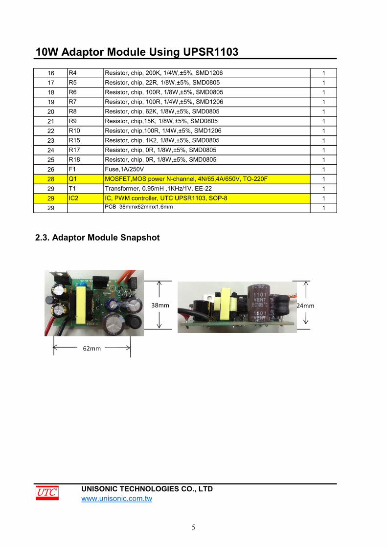
2.3. Adaptor Module Snapshot
UNISONIC TECHNOLOGIES CO., LTD www.unisonic.com.tw
MOSFET,MOS power N-channel, 4N/65,4A/650V, TO-220FTransformer, 0.95mH ,1KHz/1V, EE-22IC, PWM controller, UTC UPSR1103, SOP-8
Resistor, chip, 62K, 1/8W,±5%, SMD0805
R4
PCB 38mmx62mmx1.6mm
R6
Resistor, chip, 200K, 1/4W,±5%, SMD1206
Resistor, chip, 100R, 1/8W,±5%, SMD0805Resistor, chip, 100R, 1/4W,±5%, SMD1206
Resistor, chip, 1K2, 1/8W,±5%, SMD0805Resistor, chip, 0R, 1/8W,±5%, SMD0805
R10
Q1T1IC2
Resistor, chip, 0R, 1/8W,±5%, SMD0805Fuse,1A/250V
Resistor, chip,15K, 1/8W,±5%, SMD0805Resistor, chip,100R, 1/4W,±5%, SMD1206
R17R15
R7R8R9
Resistor, chip, 22R, 1/8W,±5%, SMD0805
F1R18
R5
62mm
38mm 24mm
5
10W Adaptor Module Using UPSR1103
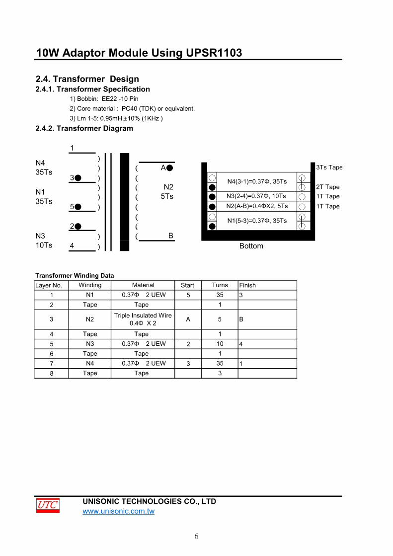
2.4. Transformer Design2.4.1. Transformer Specification
1) Bobbin: EE22 -10 Pin2) Core material : PC40 (TDK) or equivalent.3) Lm 1-5: 0.95mH,±10% (1KHz )
2.4.2. Transformer Diagram
1)
) ( A● 3Ts Tape
3● ) ( ○ ○
) ( N2 ● ○ 2T Tape) ( 5Ts ● ○ 1T Tape
5● ) ( ● ○ 1T Tape
( ○ ○
2● ( ● ○
) ( B) Bottom
Transformer Winding DataLayer No. Start Finish
1 5 32
45 2 467 3 18
UNISONIC TECHNOLOGIES CO., LTD www.unisonic.com.tw
A 5 B
351
110
0.37Φ 2 UEW
Tape
35
Turns
N4(3-1)=0.37Φ, 35Ts
0.37Φ 2 UEWTape
TapeN3
3
1
Triple Insulated Wire0.4Φ X 2
0.37Φ 2 UEWTape
Tape
N1
N135Ts
N310Ts 4
N4Tape
N2
Tape
Tape
3
N435Ts
Winding Material
N1(5-3)=0.37Φ, 35Ts
N2(A-B)=0.4ΦX2, 5TsN3(2-4)=0.37Φ, 10Ts
6
10W Adaptor Module Using UPSR1103
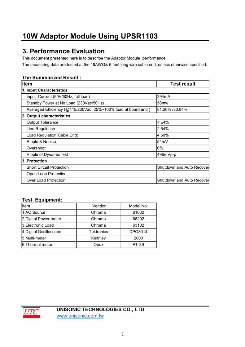
3. Performance EvaluationThis document presented here is to describe the Adaptor Module performance.The measuring data are tested at the 18AWG& 6 feet long wire cable end, unless otherwise specified.
The Summarized Result :
Test Equipment:
UNISONIC TECHNOLOGIES CO., LTD www.unisonic.com.tw
Test result
294mA58mw
496mVp-p
Line Regulation< ±4%
Over Load Protection
4.50%54mV0%
Ripple of DynamicTest3. Protection Short Circuit Protection Shutdown and Auto Recovery
Item
Input Current (90V/60Hz, full load) Standby Power at No Load (230Vac/50Hz) Averaged Efficiency (@115/230Vac, 25%~100% load at board end )
Output Tolerance
Open Loop Protection
2. Output characteristics81.26% /80.84%
2.54%
Chroma
1. Input Characteristics
Item Vendor Model No:
Load Regulation(Cable End) Ripple & Nnoise Overshoot
Shutdown and Auto Recovery
1.AC Source2.Digital Power meter3.Electronic Load4.Digital Oscilloscope5.Multi-meter6.Thermal meter
616026620263102
DPO30142000
PT-3S
ChromaChroma
TektronicsKeithleyOpex
7
10W Adaptor Module Using UPSR1103
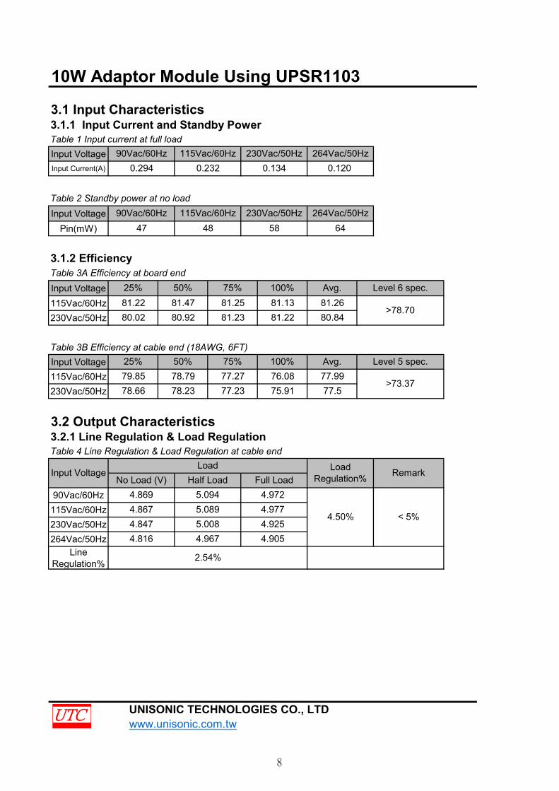
3.1 Input Characteristics3.1.1 Input Current and Standby PowerTable 1 Input current at full loadInput VoltageInput Current(A)
Table 2 Standby power at no loadInput Voltage
Pin(mW)
3.1.2 EfficiencyTable 3A Efficiency at board endInput Voltage115Vac/60Hz230Vac/50Hz
Table 3B Efficiency at cable end (18AWG, 6FT)Input Voltage115Vac/60Hz230Vac/50Hz
3.2 Output Characteristics3.2.1 Line Regulation & Load RegulationTable 4 Line Regulation & Load Regulation at cable end
90Vac/60Hz115Vac/60Hz230Vac/50Hz264Vac/50Hz
LineRegulation%
UNISONIC TECHNOLOGIES CO., LTD www.unisonic.com.tw
81.25Level 6 spec.
>78.70
Level 5 spec.
>73.37
81.1381.22
Avg.
25% 50% 75% 100% Avg.
80.84
264Vac/50Hz230Vac/50Hz0.134 0.120
64264Vac/50Hz230Vac/50Hz
58
25%
79.85 78.79 77.27 76.08 77.99
81.23
100%81.26
< 5%
115Vac/60Hz47 48
78.66 78.23 77.23
50%81.47
0.23290Vac/60Hz
0.294
90Vac/60Hz
LoadRegulation%
4.9724.977
80.92
75%
4.9254.905
Full Load
4.50%
2.54%
4.869
4.816 4.9675.0085.0894.8675.094
Half LoadInput Voltage
81.2280.02
115Vac/60Hz
No Load (V)Remark
Load
4.847
77.575.91
8
10W Adaptor Module Using UPSR1103
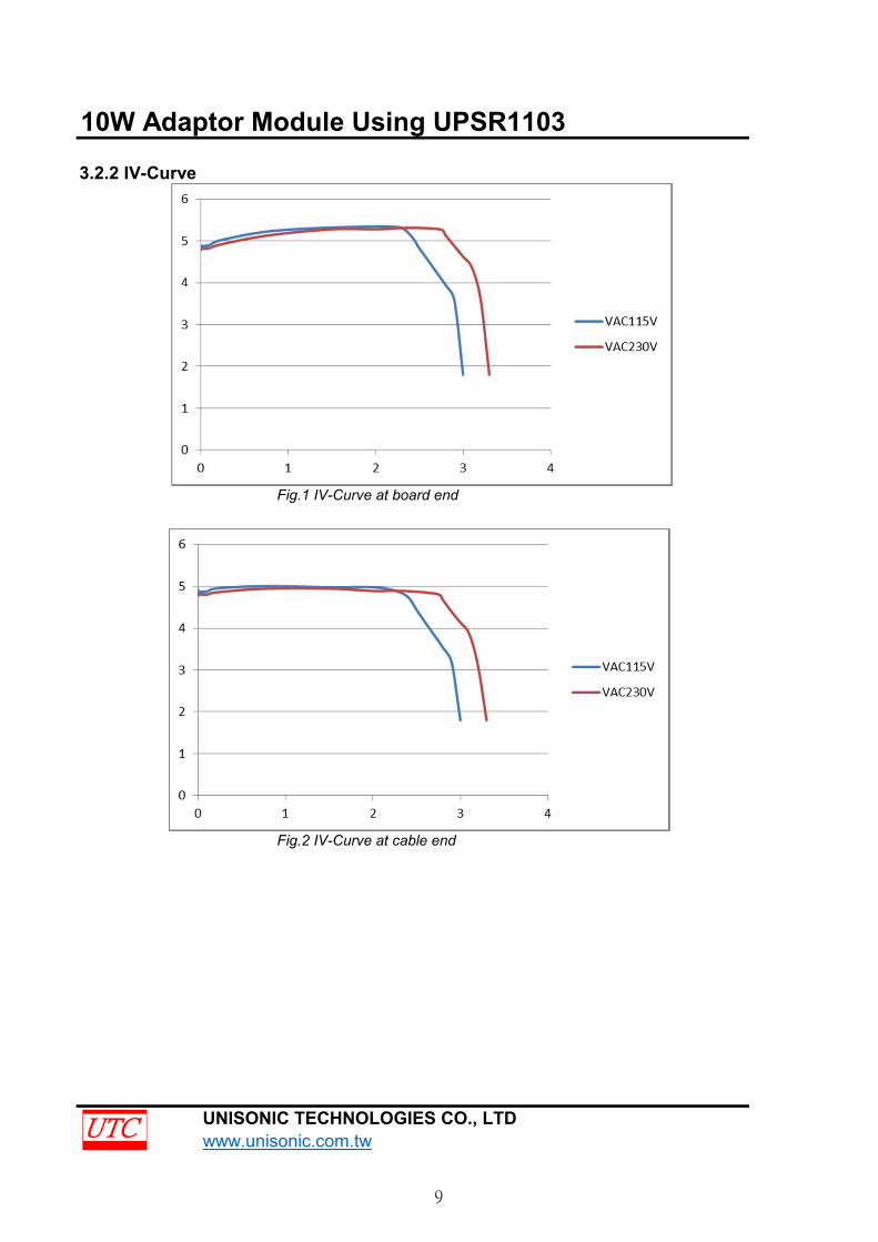
3.2.2 IV-Curve
Fig.1 IV-Curve at board end
Fig.2 IV-Curve at cable end
UNISONIC TECHNOLOGIES CO., LTD www.unisonic.com.tw
9
10W Adaptor Module Using UPSR1103
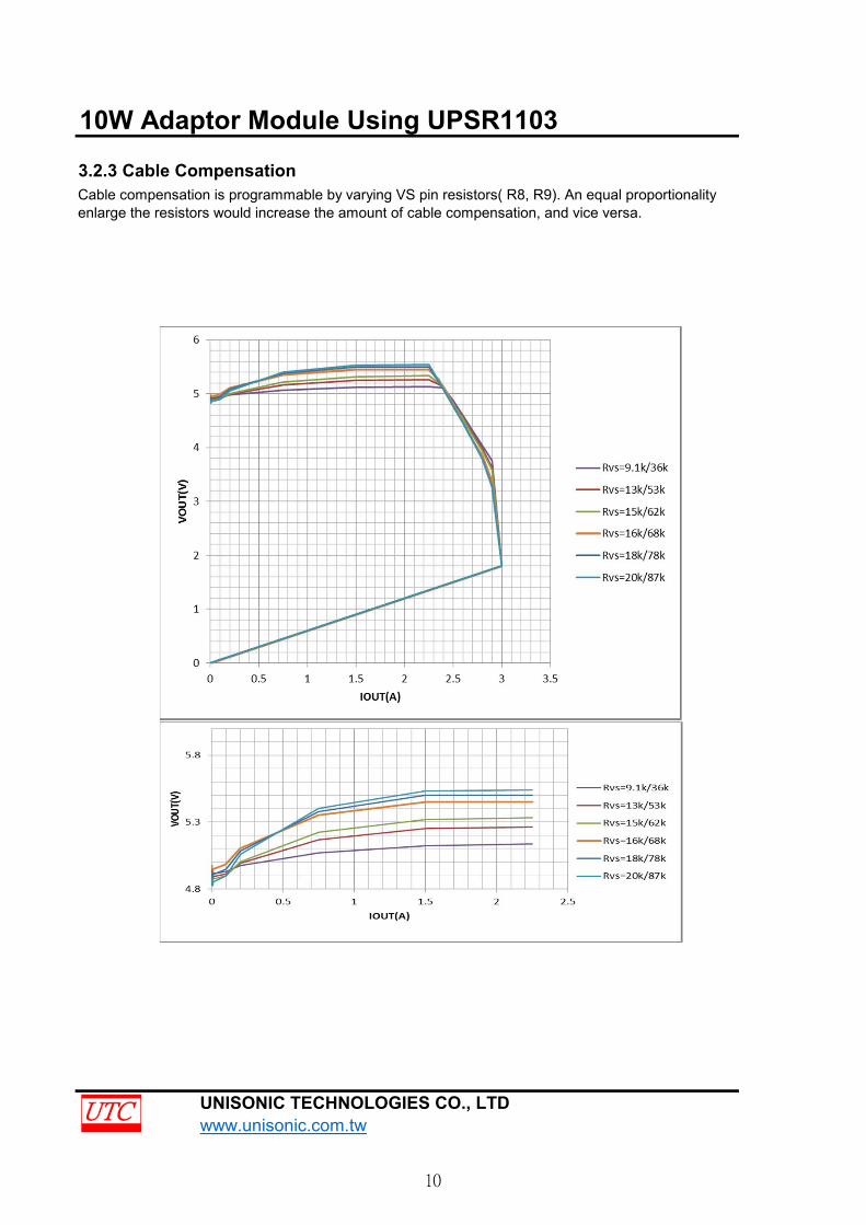
3.2.3 Cable Compensation
UNISONIC TECHNOLOGIES CO., LTD www.unisonic.com.tw
Cable compensation is programmable by varying VS pin resistors( R8, R9). An equal proportionalityenlarge the resistors would increase the amount of cable compensation, and vice versa.
10
10W Adaptor Module Using UPSR1103
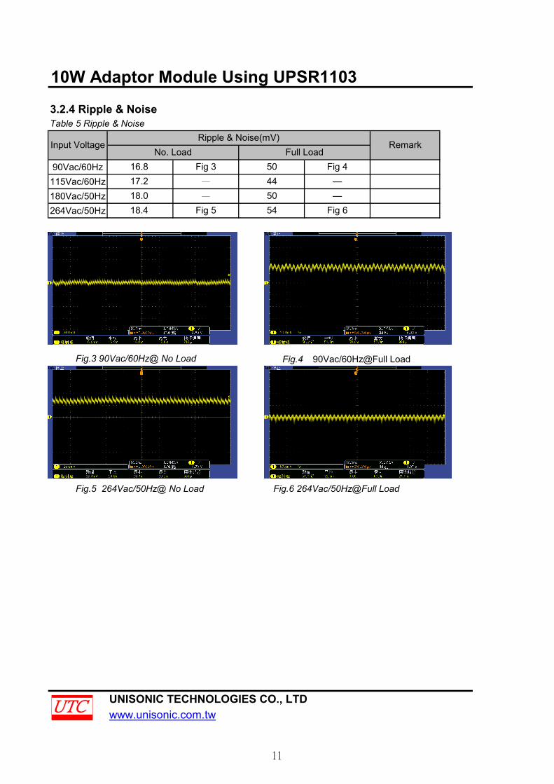
3.2.4 Ripple & NoiseTable 5 Ripple & Noise
90Vac/60Hz115Vac/60Hz180Vac/50Hz264Vac/50Hz
UNISONIC TECHNOLOGIES CO., LTDwww.unisonic.com.tw
Remark
Fig.6 264Vac/50Hz@Full Load
Ripple & Noise(mV)
Fig.3 90Vac/60Hz@ No Load Fig.4 90Vac/60Hz@Full Load
Fig.5 264Vac/50Hz@ No Load
16.817.218.018.4
Input VoltageNo. Load
Fig 650 —
5044
Full LoadFig 4
—Fig 3
Fig 5 54
—
—
11
10W Adaptor Module Using UPSR1103
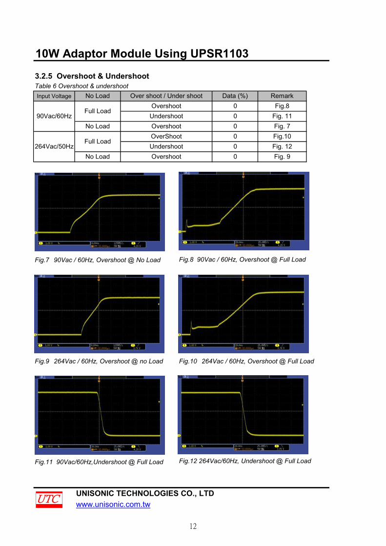
3.2.5 Overshoot & UndershootTable 6 Overshoot & undershootInput Voltage
Fig.7 90Vac / 60Hz, Overshoot @ No Load Fig.8 90Vac / 60Hz, Overshoot @ Full Load
Fig.9 264Vac / 60Hz, Overshoot @ no Load Fig.10 264Vac / 60Hz, Overshoot @ Full Load
Fig.11 90Vac/60Hz,Undershoot @ Full Load Fig.12 264Vac/60Hz, Undershoot @ Full Load
UNISONIC TECHNOLOGIES CO., LTDwww.unisonic.com.tw
No Load
Over shoot / Under shootOvershootUndershootOvershootOverShootUndershootOvershoot
No Load
Full Load
No Load
Full Load
Fig.8Fig. 11Fig. 7Fig.10Fig. 12
Remark
0
Data (%)
Fig. 9264Vac/50Hz
90Vac/60Hz
00
0
0
0
12
10W Adaptor Module Using UPSR1103
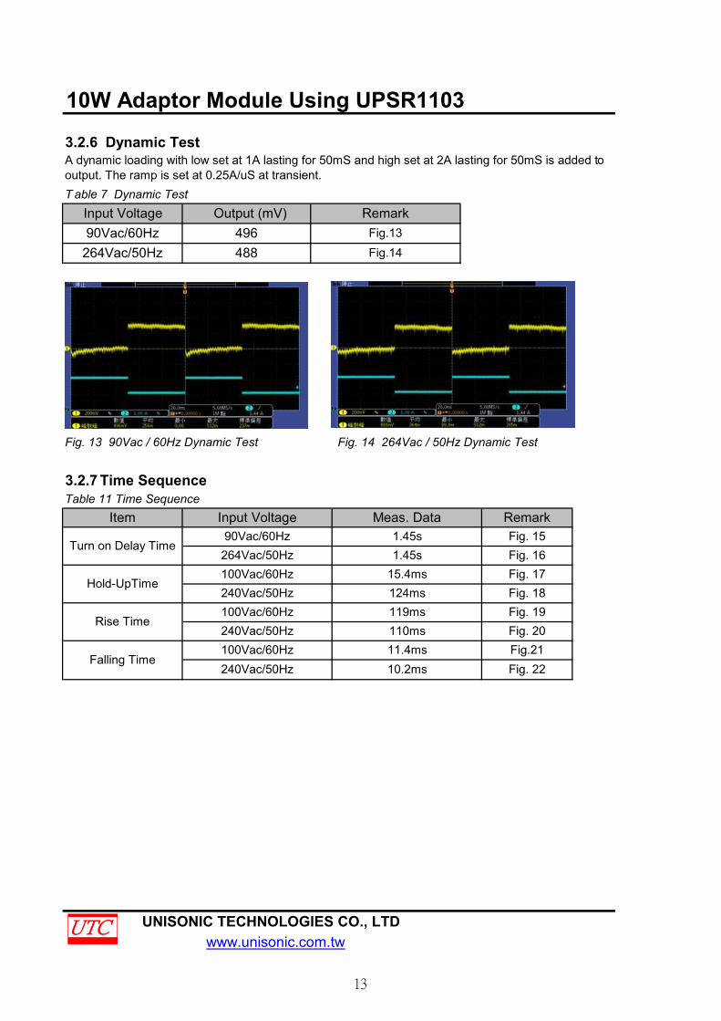
3.2.6 Dynamic Test
T able 7 Dynamic Test
Fig. 13 90Vac / 60Hz Dynamic Test Fig. 14 264Vac / 50Hz Dynamic Test
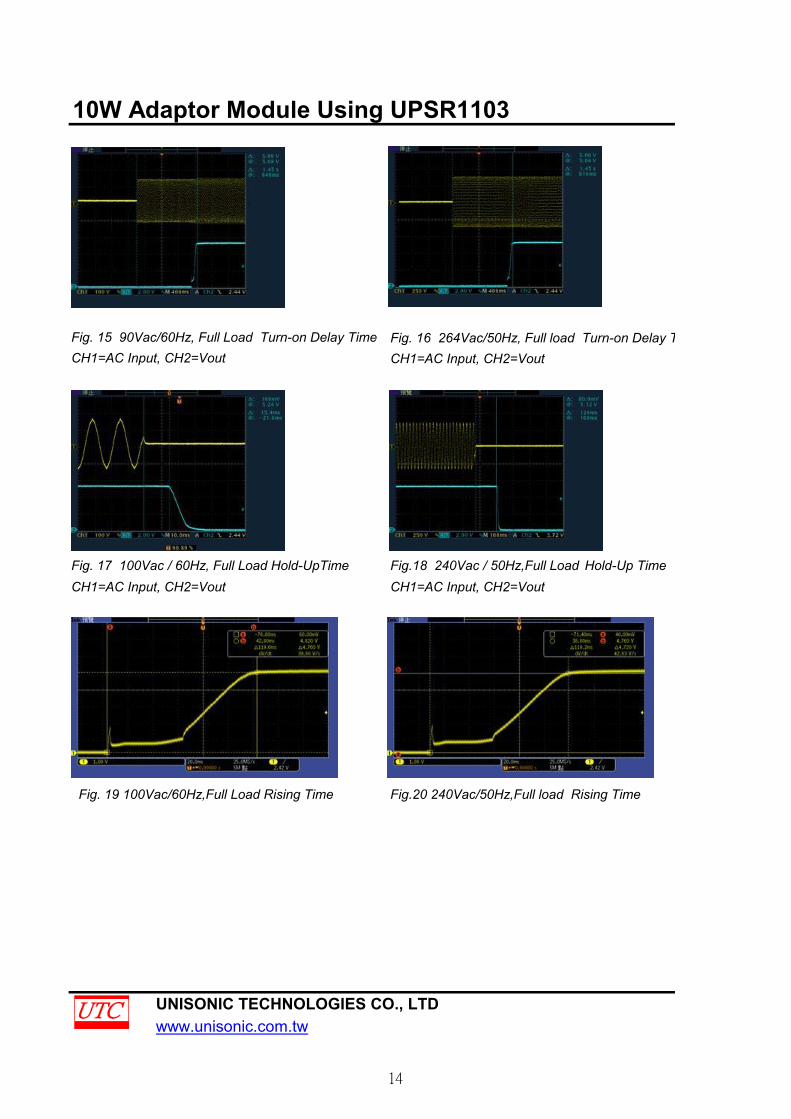
3.2.7 Time SequenceTable 11 Time Sequence
UNISONIC TECHNOLOGIES CO., LTDwww.unisonic.com.tw
Output (mV)496488
Fig. 161.45s
Remark
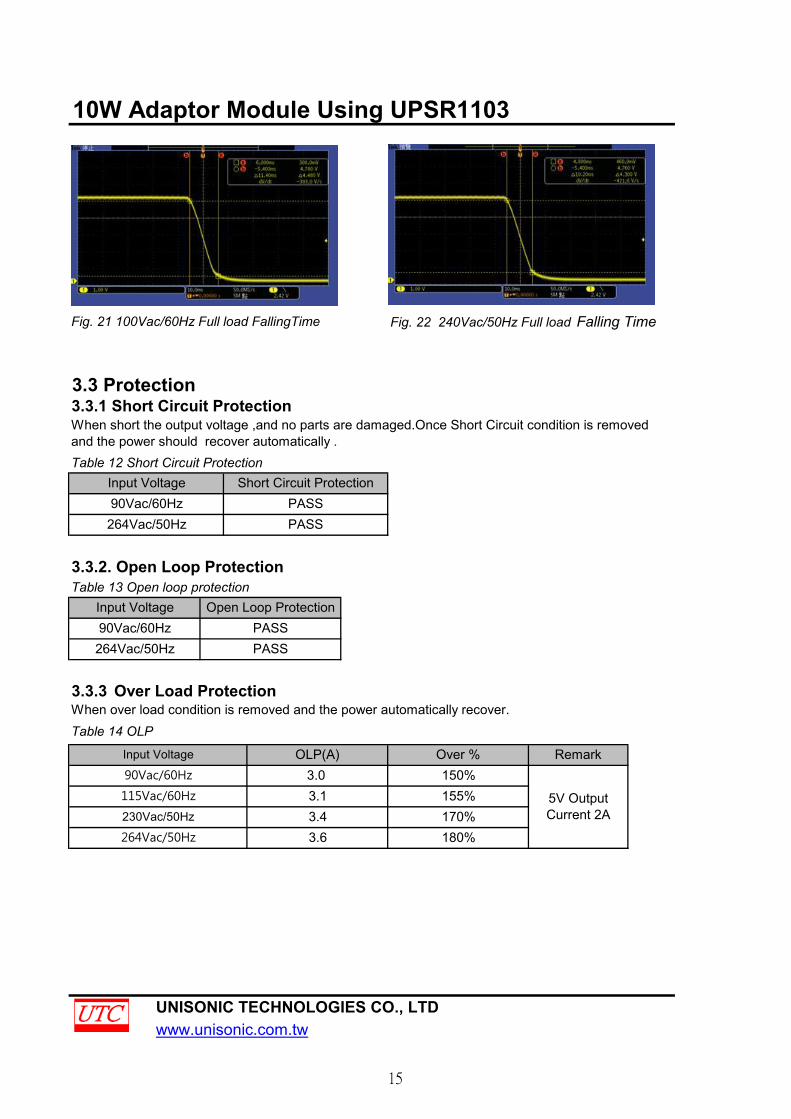
Fig. 17Fig. 18Fig. 19Fig. 20Fig.21Fig. 2210.2ms
Falling Time11.4ms110ms
Rise Time119ms
Hold-UpTime15.4ms100Vac/60Hz
1.45sItem
Input Voltage90Vac/60Hz
Fig. 15Input Voltage90Vac/60Hz264Vac/50Hz
240Vac/50Hz
Turn on Delay Time
Meas. Data
264Vac/50Hz
124ms
RemarkFig.13Fig.14
100Vac/60Hz240Vac/50Hz
A dynamic loading with low set at 1A lasting for 50mS and high set at 2A lasting for 50mS is added tooutput. The ramp is set at 0.25A/uS at transient.
100Vac/60Hz240Vac/50Hz
13
10W Adaptor Module Using UPSR1103
Fig. 16 264Vac/50Hz, Full load Turn-on Delay TimeCH1=AC Input, CH2=Vout
CH1=AC Input, CH2=Vout CH1=AC Input, CH2=Vout
Fig. 19 100Vac/60Hz,Full Load Rising Time Fig.20 240Vac/50Hz,Full load Rising Time
UNISONIC TECHNOLOGIES CO., LTDwww.unisonic.com.tw
CH1=AC Input, CH2=Vout
Fig.18 240Vac / 50Hz,Full Load Hold-Up TimeFig. 17 100Vac / 60Hz, Full Load Hold-UpTime
Fig. 15 90Vac/60Hz, Full Load Turn-on Delay Time
14
10W Adaptor Module Using UPSR1103
Fig. 21 100Vac/60Hz Full load FallingTime Fig. 22 240Vac/50Hz Full load Falling Time
3.3 Protection
Table 12 Short Circuit Protection
3.3.2. Open Loop ProtectionTable 13 Open loop protection
When over load condition is removed and the power automatically recover.Table 14 OLP
UNISONIC TECHNOLOGIES CO., LTDwww.unisonic.com.tw
170%180%
PASSPASS
When short the output voltage ,and no parts are damaged.Once Short Circuit condition is removedand the power should recover automatically .
Input Voltage
115Vac/60Hz
Input Voltage90Vac/60Hz264Vac/50Hz
Open Loop Protection
3.3.1 Short Circuit Protection
Remark
PASS
3.3.3 Over Load Protection
264Vac/50Hz90Vac/60HzInput Voltage
5V OutputCurrent 2A
OLP(A) Over %90Vac/60Hz 3.0 150%
PASS
3.4
Short Circuit Protection
230Vac/50Hz
264Vac/50Hz 3.6
155%3.1
15
10W Adaptor Module Using UPSR1103
Tested at Room temperature 35℃ in Plastic ABS Case.(Case Dimension 61mmX35mmX120mm).Table 15 Thermal TestingInput Voltage90Vac/60Hz
UNISONIC TECHNOLOGIES CO., LTDwww.unisonic.com.tw
Transformer61.5℃ 61.4℃ 69℃ 80.6℃
3.3.4 Thermal Testing
UPSR1103 MOSFET Schottky
16
10W Adaptor Module Using UPSR1103
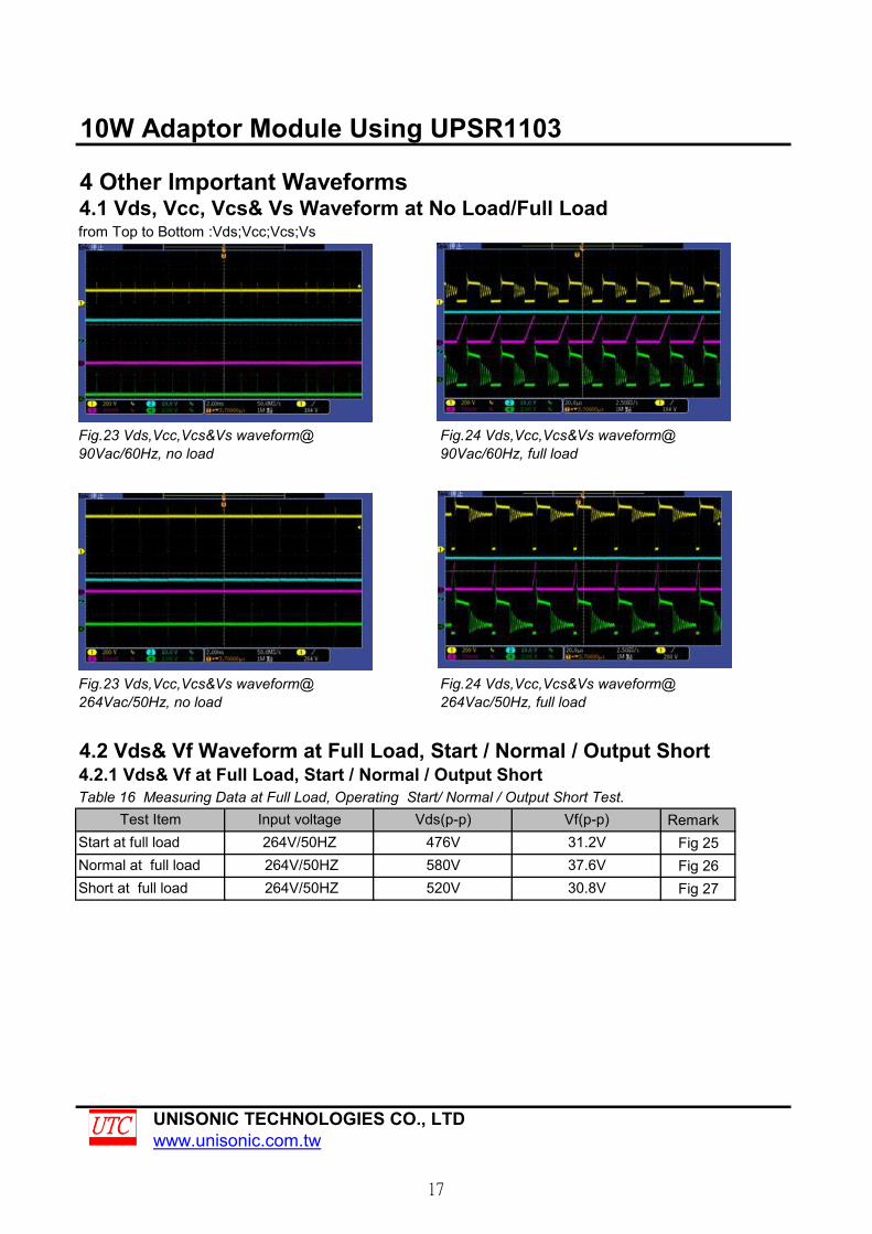
4 Other Important Waveforms4.1 Vds, Vcc, Vcs& Vs Waveform at No Load/Full Loadfrom Top to Bottom :Vds;Vcc;Vcs;Vs
4.2 Vds& Vf Waveform at Full Load, Start / Normal / Output Short4.2.1 Vds& Vf at Full Load, Start / Normal / Output ShortTable 16 Measuring Data at Full Load, Operating Start/ Normal / Output Short Test.
RemarkFig 25Fig 26Fig 27
UNISONIC TECHNOLOGIES CO., LTDwww.unisonic.com.tw
Fig.23 Vds,Vcc,Vcs&Vs waveform@90Vac/60Hz, no load
Fig.24 Vds,Vcc,Vcs&Vs waveform@90Vac/60Hz, full load
Fig.23 Vds,Vcc,Vcs&Vs waveform@264Vac/50Hz, no load
Fig.24 Vds,Vcc,Vcs&Vs waveform@264Vac/50Hz, full load
Vds(p-p)476V
Vf(p-p)31.2V
264V/50HZ
Test ItemStart at full load 264V/50HZ Normal at full load
Input voltage
264V/50HZ 580V520V
37.6V30.8VShort at full load
17

10W Adaptor Module Using UPSR1103
Fig.25 Vds& Vf start waveform@264Vac/50Hz, full load
Fig.26 Vds& Vf normal waveform@264Vac/50Hz, full load
Fig.27 Vds& Vf output short waveform@264Vac/50Hz, full load
UNISONIC TECHNOLOGIES CO., LTDwww.unisonic.com.tw
4.2.4 Vds& Vf at full load, output short waveform
4.2.2 Vds& Vf at full load, start waveform
4.2.3 Vds& Vf at full load, normal waveform
18