10IN. COMPOUND MITER SAW - Northern Tool OF 20 10IN. COMPOUND MITER SAW OWNER’S MANUAL WARNING:...
20
1 OF 20 10IN. COMPOUND MITER SAW OWNER’S MANUAL WARNING: Read carefully and understand all ASSEMBLY AND OPERATION INSTRUCTIONS before operating. Failure to follow the safety rules and other basic safety precautions may result in serious personal injury. Item # 46463
Transcript of 10IN. COMPOUND MITER SAW - Northern Tool OF 20 10IN. COMPOUND MITER SAW OWNER’S MANUAL WARNING:...

1 OF 20
10IN. COMPOUND MITER SAW
OWNER’S MANUAL
WARNING: Read carefully and understand all ASSEMBLY AND OPERATION INSTRUCTIONS before operating. Failure to follow the safety rules and other basic safety precautions may result in serious personal injury.
Item # 46463

2 OF 20
Thank you very much for choosing an Ironton Product! For future reference, please complete the owner’s record below: Model: _______________ Purchase Date: _______________ Save the receipt, warranty and these instructions. It is important that you read the entire manual to become familiar with this product before you begin using it. This machine is designed for certain applications only. The distributor strongly recommends this machine is not modified and/or used for any application other than that for which it was designed. If you have any questions relative to a particular application, DO NOT use the machine until you have first contacted the distributor to determine if it can or should be performed on the product. For technical questions and replacement parts, please call 1-800-222-5381.
INTENDED USE The Ironton Compound Miter Saw’s impressive 2.4 HP, 15 Amp motor gives you the power you need to cut both wood and composite materials without slowing down.
TECHNICAL SPECIFICATIONS ITEM DESCRIPTION
Motor 120 VAC / 60 Hz / 15 A 5,000 RPM Arbor Diameter 5/8in. Recommended Blade Type General Purpose with Carbide Tips Blade Diameter 10in. Cutting Capacity At 90°: 2-3/4″ Deep x 12in. wide. At 45° 1-9/16in. Deep x 8-1/4in. Wide. Positive Table Stops 0°, 15°, 22.5°, 30° and 45° Right and Left Positive Bevel Stops 0° and 45° Left only Blade Tilt Range 0° - 45° Right and Left; Miter 0° - 45° left Scale 1° per scale mark

3 OF 20
GENERAL SAFETY RULES
WARNING: Read and understand all instructions. Failure to follow all instructions listed below may result in serious injury.
CAUTION: Do not allow persons to operate or assemble this Compound Miter Saw until they have read this manual and have developed a thorough understanding of how the Compound Miter Saw works.
WARNING: The warnings, cautions, and instructions discussed in this instruction manual cannot cover all possible conditions or situations that could occur. It must be understood by the operator that common sense and caution are factors that cannot be built into this product, but must be supplied by the operator.
SAVE THESE INSTRUCTIONS
COMPOUND MITER SAW USE AND CARE • Do not modify the Compound Miter Saw in any way. Unauthorized modification may impair the
function and/or safety and could affect the life of the equipment. There are specific applications for which the Compound Miter Saw was designed.
• Always check of damaged or worn out parts before using the Compound Miter Saw. Broken parts will affect the Compound Miter Saw operation. Replace or repair damaged or worn parts immediately.
• Store idle Compound Miter Saw. When Compound Miter Saw is not in use, store it in a secure place out of the reach of children. Inspect it for good working condition prior to storage and before re-use.
PRODUCT FEATURES Powerful, precise compound saw that makes accurate and repeatable angle cuts. The electric blade-brake stops the blade in seconds for safety. External access block brushes for convenient maintenance/replacement of brushes. A dust bag keeps the work area clean and improves viewing of the workpiece during cutting. Precision machined table with graduated scale and pin presets. The vise assembly and support brackets improve cutting accuracy. A transparent, retractable blade guard improves safety while providing good visibility.
GENERAL SAFETY WARNINGS AND PRECAUTIONS Keep the work area clean and dry. Damp or wet work areas will lead to injuries. Keep children away from the work area. Do not allow children to operate this product. Store idle equipment. When not in use, tools and equipment should be stored in a dry location
to inhibit rust. Always lock up tools and equipment and keep them out of the reach of children. Do not use this product if under the influence of alcohol or drugs. Read warning labels on
prescriptions to determine if your judgment or reflexes are impaired while taking drugs. If there is any doubt, do not attempt to use this product.
4 OF 20
Dress properly. Do not wear loose clothing or jewelry. Contain long hair. Keep your hair, clothing, and gloves away from moving parts. Loose clothes, jewelry or long hair can be caught in moving parts.
Avoid accidental starting. Be sure the switch is OFF before plugging in the tool. Carrying tools with your finger on the switch or plugging in tools that have the switch ON invites accidents.
Remove all adjusting keys and wrenches. Make a habit of checking that the adjusting keys and wrenches are removed from the tool before turning it on.
Do not overreach. Keep proper footing and balance at all times. Proper footing and balance allows for better control of the tool in unexpected situations.
Use safety equipment. Eye protection should be worn at all times when operating this machine. Use ANSI Z87.1 approved safety glasses. Everyday eyeglasses only have impact resistance lenses. They are NOT safety glasses. A dust mask, respirator, non-skid safety shoes, a hard hat, or hearing protection must be used in appropriate conditions.
Not intended for commercial use. Stay alert. Watch what you are doing at all times. Use common sense. Do not use this product
when you are tired or distracted from the job at hand. Check for damaged parts. Before using this product, carefully check to ensure that the saw will
operate properly and perform its intended function. Check for damaged parts and any other conditions that may affect the operation of this product. Replace or repair damaged or worn parts immediately.
Replacement parts and accessories. When servicing, use only manufacturer supplied replacement parts. Only use accessories intended for use with this product. Please call 1-800-222-5381 for replacement parts.
Maintain this product with care. Keep this product clean and dry, and keep the saw blades clean and sharp for better and safer performance.
For your safety, a qualified technician should perform service and maintenance regularly. Use the right product for the right job. There are certain applications for which this product was
designed. Do not use small equipment, tools or attachments to do the work of larger industrial equipment, tools or attachments.
Do not use this product for a purpose for which it was not intended.
ELECTRICAL SAFETY The electrical power cord for this product is equipped with a 2-prong plug. Never modify the
plug in any way. Do not use adapter plugs with this product. When in use, make sure this product is always plugged into a grounded electrical receptacle with an appropriate breaker switch.
Make sure the power switch is in the “off” position before plugging in the power cord. Do not abuse the power cord. Do not use the cord to pull the 2-prong plug from the power outlet.
Keep the cord away from heat, oil, sharp edges and moving parts. Replace a damaged cord immediately. Route the power cord safely. Protect it from being damaged by other equipment in the shop. Do not route the cord where it can be walked on or tripped over.
To avoid accidental electric shock, do not let your body come in contact with grounded surfaces such as pipes, radiators, ranges and refrigerators.
5 OF 20
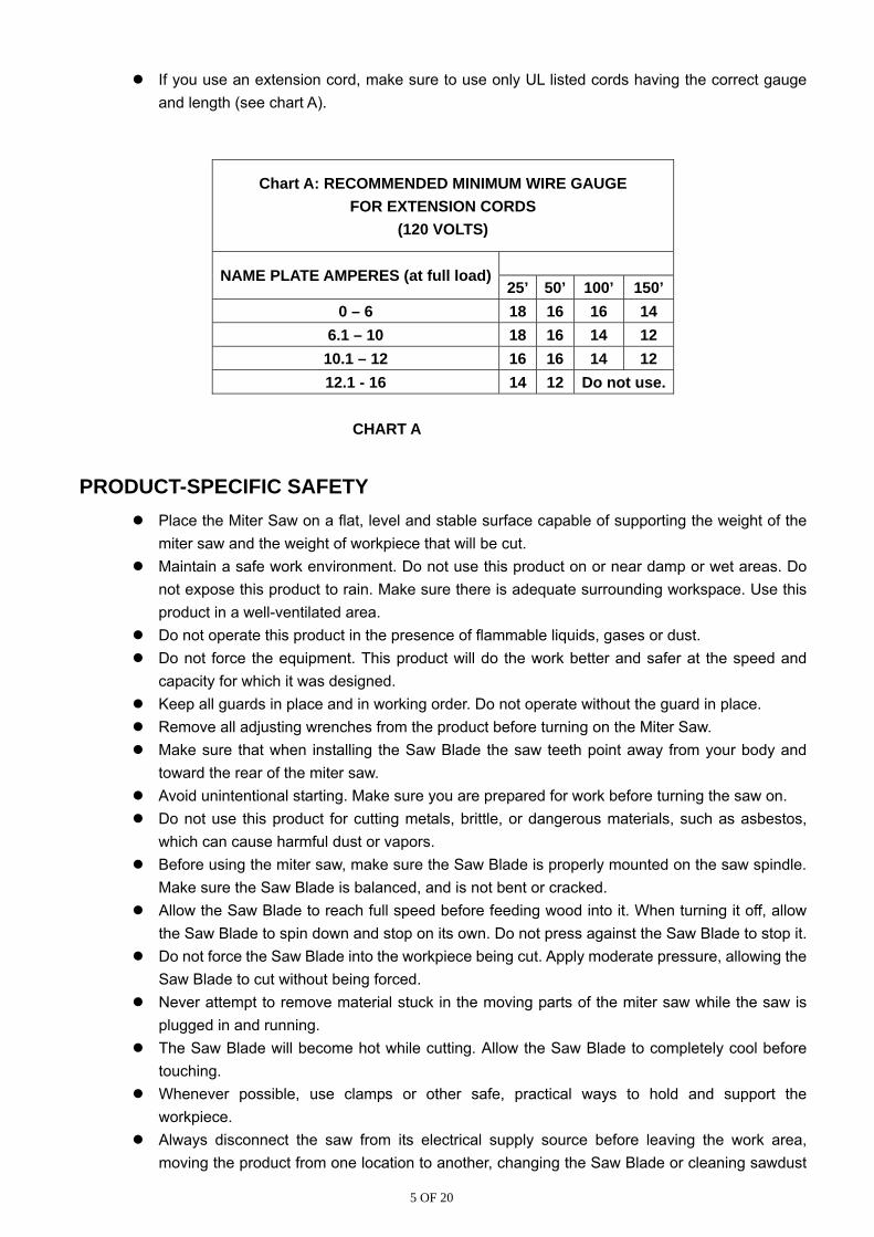
If you use an extension cord, make sure to use only UL listed cords having the correct gauge and length (see chart A).
Chart A: RECOMMENDED MINIMUM WIRE GAUGE FOR EXTENSION CORDS
(120 VOLTS)
NAME PLATE AMPERES (at full load)
25’ 50’ 100’ 150’ 0 – 6 18 16 16 14
6.1 – 10 18 16 14 12 10.1 – 12 16 16 14 12 12.1 - 16 14 12 Do not use.
CHART A
PRODUCT-SPECIFIC SAFETY Place the Miter Saw on a flat, level and stable surface capable of supporting the weight of the
miter saw and the weight of workpiece that will be cut. Maintain a safe work environment. Do not use this product on or near damp or wet areas. Do
not expose this product to rain. Make sure there is adequate surrounding workspace. Use this product in a well-ventilated area.
Do not operate this product in the presence of flammable liquids, gases or dust. Do not force the equipment. This product will do the work better and safer at the speed and
capacity for which it was designed. Keep all guards in place and in working order. Do not operate without the guard in place. Remove all adjusting wrenches from the product before turning on the Miter Saw. Make sure that when installing the Saw Blade the saw teeth point away from your body and
toward the rear of the miter saw. Avoid unintentional starting. Make sure you are prepared for work before turning the saw on. Do not use this product for cutting metals, brittle, or dangerous materials, such as asbestos,
which can cause harmful dust or vapors. Before using the miter saw, make sure the Saw Blade is properly mounted on the saw spindle.
Make sure the Saw Blade is balanced, and is not bent or cracked. Allow the Saw Blade to reach full speed before feeding wood into it. When turning it off, allow
the Saw Blade to spin down and stop on its own. Do not press against the Saw Blade to stop it. Do not force the Saw Blade into the workpiece being cut. Apply moderate pressure, allowing the
Saw Blade to cut without being forced. Never attempt to remove material stuck in the moving parts of the miter saw while the saw is
plugged in and running. The Saw Blade will become hot while cutting. Allow the Saw Blade to completely cool before
touching. Whenever possible, use clamps or other safe, practical ways to hold and support the
workpiece. Always disconnect the saw from its electrical supply source before leaving the work area,
moving the product from one location to another, changing the Saw Blade or cleaning sawdust

6 OF 20
from the unit. Never reach around saw. Keep hands out of path of saw blade. Never reach in back of the
fence.
MITER SAW SAFETY WARNINGS For Your Own Safety Read Instruction Manual Before Operating Miter Saw
Wear eye protection. Keep hands out of path of saw blade. Do not operate saw without guards in place. Do not perform any operation freehand. Never reach around saw blade. Turn off tool and wait for saw blade to stop before moving workpiece or changing settings. Disconnect power before changing blade or servicing. Return all guards to original position if any are moved during blade replacement. Check all
guards for proper operation after service. Always use blades with correct size and shape (diamond versus round) of arbor holes. Blades
that do not match the mounting hardware of the saw will run eccentrically, causing loss of control.
Never use damaged or incorrect blade washers or bolt. The blade washers and bolt were specially designed for your saw, for optimum performance and safety of operation.
Do not use to cut logs, tree limbs, or uneven lumber. Wet lumber, green (unseasoned) lumber, and pressure treated lumber all have an increased
potential for kickback and should only be cut with a blade for cutting that lumber type. Wear a NIOSH-approved respirator and have appropriate ventilation whenever cutting pressure treated lumber.
Do not use blades made from high-speed steel, abrasive blades, metal-cutting blades or masonry-cutting blades. The guards of this saw are not designed to protect against the failure of such blades.
Blades must be rated to at least the maximum speed marked on the tool. DO NOT OPERATE WITH ANY GUARD DISABLED, DAMAGED, OR REMOVED. Moving
guards must move freely and close instantly. The use of accessories or attachments not recommended by the manufacturer may result in a
risk of injury to persons. When servicing use only identical replacement parts. Do not depress the spindle lock when starting or during operation. Only use safety equipment that has been approved by an appropriate standards agency.
Unapproved safety equipment may not provide adequate protection. Eye protection must be ANSI-approved and breathing protection must be NIOSH-approved for the specific hazards in the work area.
Stay alert, watch what you are doing and use common sense when operating a power tool. Do not use a power tool while you are tired or under the influence of drugs, alcohol or medication. A moment of inattention while operating power tools may result in serious personal injury.
Industrial applications must follow OSHA guidelines. Maintain labels and nameplates on the tool. These carry important safety information. If
unreadable or missing, contact the distributor for a replacement. Avoid unintentional starting. Prepare to begin work before turning on the tool. People with pacemakers should consult their physician(s) before use. Electromagnetic fields in
7 OF 20
close proximity to heart pacemaker could cause pacemaker interference or pacemaker failure.
VIBRATION SAFETY This tool vibrates during use. Repeated or long-term exposure to vibration may cause temporary or permanent physical injury, particularly to the hands, arms and shoulders. To reduce the risk of vibration-related injury:
Anyone using vibrating tools regularly or for an extended period should first be examined by a doctor and then have regular medical check-ups to ensure medical problems are not being caused or worsened from use. Pregnant women or people who have impaired blood circulation to the hand, past hand injuries, nervous system disorders, diabetes, or Raynaud’s Disease should not use this tool. If you feel any medical or physical symptoms related to vibration (such as tingling, numbness, and white or blue fingers), seek medical advice as soon as possible.
Do not smoke during use. Nicotine reduces the blood supply to the hands and fingers, increasing the risk of vibration-related injury.
Use tools with the lowest vibration when there is a choice between different processes. Include vibration-free periods each day of work. Grip tool as lightly as possible (while still keeping safe control of it). Let the tool do the work. To reduce vibration, maintain the tool as explained in this manual. If any abnormal vibration
occurs, stop use immediately.
UNPACKING When unpacking, check to make sure that all the parts shown on the Parts List and Diagram are included. If any parts are missing or broken, please call the distributor at the number shown in this manual as soon as possible.
SETUP – BEFORE USE:
WARNING: TO PREVENT SERIOUS INJURY FROM ACCIDENTAL OPERATION: Turn the Power Switch of the tool to its “OFF” position and unplug the tool from its electrical outlet before assembling or making any adjustments to the tool.
ASSEMBLY Attaching the Extension Supports and Miter Lock Handle 1. Insert the ends of the Extension Supports into the holes in the sides of the Base. Tighten the Wing
Screws to hold the Extensions in place. The upper edge of the Extensions will be level with the surface of the saw. This provides a wider base for the work material to rest on.
2. Thread the Miter Lock Handle into the Plate until securely in place. Attaching the Dust Collection Bag 3. The Dust Collection Bag slips over the Dust Outlet behind the Blade Housing Assembly. Sawdust
created by cutting is captured in the bag.
MOUNTING THE SAW The Miter Saw must be mounted on a support before use. This may be a commercially available support or

8 OF 20
home made saw table. There are bolt holes provided in each of the four legs of the base. These should be firmly mounted using bolts (not included) to your saw stand or saw table (not included). This will help prevent tipping or movement of the saw, preventing injury. Also, the use of a saw table will make it easier to efficiently handle work materials and make more accurate cuts.
OPERATING INSTRUCTIONS NOTE: All parts below refer to the parts listed in this manual.
WARNING: TO PREVENT SERIOUS INJURY FROM ACCIDENTAL OPERATION: Unplug power cord from power source before making any adjustments to this tool.
WORK PIECE AND WORK AREA SETUP Designate a work area that is clean and well lit. The work area must not allow access by children
or pets to prevent injury and distraction. Route the power cord along a safe route to reach the work area without creating a tripping hazard
or exposing the power cord to possible damage. The power cord must reach the work area with enough extra length to allow free movement while working.
Use a saw table, saw stand or other means to support the work piece. The Miter Saw must be mounted in such a way that the surface is level to the ground, and supports used must provide a surface on the same level as the saw table. If the work surface and any work materials supports are not level, and on the same level, unwanted bevel angles will appear in the cuts resulting in poor joinery.
Work pieces may be secured to the saw table using the Hold Down Clamp or other clamping devices (not included). Securing the work piece will provide safety by preventing kick back and by removing the need to hold work pieces near the blade by hand. Clamping the work piece will also improve cutting accuracy by preventing the work piece from moving during the cutting operation.
When using this saw, work pieces are often quite long. Allow room on both left and right of saw for extended work pieces.
TOOL SETUP
USING THE WORK PIECE EXTENSION SUPPORTS The Work Piece Extension Supports are inserted into each side of the Table, and locked in place
using the Wing Screws. When properly installed, the upper face of the Work Piece Extension Supports are level with the
Table, and provide a wider support surface for the work piece. Always support the work piece to be level with the table, and so that after the cut is made the cut
off pieces will not fall. You may need to use saw horses or other supports (not included) to support the work piece.
If the work piece is not level, you will make an unintentional bevel cut in the material. If the work piece is not supported, it will bind the blade and may cause the material to kick back, potentially causing injury.
9 OF 20
ADJUSTING THE MITER ANGLE A miter cut is one that is at an angle across the horizontal surface of the material. You will
commonly make 45º miter cuts to join two pieces in a right angle corner. A 30º cut is often used for a scarf joint or to make a chamfered end.
To make a miter cut, loosen the Miter Lock Knob by turning it approximately 1/4 turn counterclockwise. Press down the Thumb Lever to unlock the Table. While holding the Thumb Lever down, move the Table to the desired angle. The Miter Angle Indicator will indicate the selected angle. The table will lock into place at often used miter angles, including 22.5º, 30º, 45º, and 90º on both left and right sides.
With the Table adjusted to the desired angle, place the work piece flush against the Fence, secure it with the Hold Down Clamp and make the cut.
ADJUSTING THE BEVEL ANGLE A bevel cut is one that is at an angle to the vertical plane of the material. Bevel cuts can be used to miter relatively wide and thin material. Bevel cuts can be used in
combination with a miter cut to form a compound angle. Compound angle cuts are often used in crown moldings, picture frames and similar trim materials.
To set the bevel angle, loosen the Bevel Lock Handle at the rear of the saw. To do this, press in the Lock Button and rotate the Handle 1/2 turn counterclockwise. Move the blade assembly left to the desired angle. You can read the angle on the Bevel Angle Indicator. Lock the blade assembly into position by pressing in the Lock Button and rotating the Bevel Lock Handle clockwise. Tighten firmly but not over-tight.
Make a sample cut in a piece of scrap and check to be sure the bevel angle is correct. If it is not, correct the angle before cutting your work material.
USING THE DEPTH STOP If you want to make a kerfing or rabbet cut which does not cut through the work piece, you can use
the Depth Stop Screw to control the depth of the cut. To limit blade assembly travel, turn the Depth Stop Screw clockwise. The further you screw down
the Depth Stop Screw, the shallower the cut will be. After the desired cut has been made, return the Depth Stop Screw to its open position by turning it
counterclockwise.
GENERAL OPERATING INSTRUCTIONS When the Handle is lowered, the Blade Guard raises automatically. When the Handle is raised the
Blade Guard returns to its safety position. Keep hands clear of the Blade when the Handle is lowered. Never interfere with the proper movement of the Blade Guard.
There are locking mechanisms for the miter angle and the Slides. Unlock the Table to set the miter angle, then re-lock it before making the cut. Unlock the Slide using the Slide Lock Wing Screw before making a cut if the work material is too wide to “chop.”
To rotate the Table, press down the Miter Thumb Lever, rotate the Table to the desired angle, then release the Miter Lock Lever. Notches are machined into the Base of the tool, which will lock the Table into several often used miter angles. These angles are 0º (centered), 15º, 22.5º, 30º and 45º both left and right cut.
On wider pieces, you will have to slide the blade while making the cut. To unlock the Slide, loosen

10 OF 20
the Slide Lock Wing Screw at the back of the saw. To make a bevel cut, release the Bevel Lock Lever; rotate the blade assembly to the desired bevel
angle, then lock the blade assembly in place using the Bevel Lock Lever. Making bevel cuts is discussed in more detail later in this manual.
This saw is provided with a Kerf Board. The Kerf Board helps to prevent tear-out on the bottom side of the work material. The Kerf Board is factory adjusted prior to shipment of this tool so the blade does not contact the Kerf Board during normal operation, including bevel cuts. Adjustment of the Kerf Board and techniques to prevent tear-out are discussed later in this booklet.
Before starting work, check the accuracy of the Guide Fence, miter angle and bevel angle. Instructions for checking and adjusting these angles are discussed later in this booklet.
It is very important that the work material be properly supported before making a cut. The material must be level on the Table. The material must be supported on both ends. Using the Work Piece Extension Supports is discussed in the next section.
Use this saw only for its intended purpose of cutting flat rectangular or round wood stock, or finished molding. Do not use it for cutting firewood, brush, or anything that does not lie flat on the table. Doing so may cause binding or violent kick-back that may result in damage or personal injury.
MAKING A CUT Observe all safety and planning items discussed in this booklet. Detailed instructions on each of the
following steps are discussed in this booklet. Do not make any cuts until you have read this entire booklet and are familiar with the operation of this tool.
Release the Locking Pin to allow the blade assembly to come up. Check to be sure the Table is fixed in place at the desired miter angle. Check to be sure the slide lock is released to allow the blade assembly to slide freely.
Blow any sawdust or debris away from the Fence. Place the work material against the Fence. Make any necessary miter or bevel adjustments. Align the marked location of the cut on the work material with the saw blade. Be aware that the Saw
Blade will remove material from the cut equal to the width of the blade. This is the “kerf”. To prevent your work piece from being cut too short, align the edge of the blade with your measured mark, keeping the kerf on the waste side of the cut.
Hold the work material in place using the Hold Down Vise. Ensure that the work material is level and supported securely, using saw horses or supports if necessary.
Grip the Saw Handle and squeeze the Trigger to start the Blade turning. Pressing down lightly, move the Blade smoothly across the work material to cut it. With narrow material,
you can press straight down “chopping” the material. With wider material you must move the Blade across the material to cut it. Do not bear down on the material, use light downward pressure. If the material binds the blade, release the trigger. Keep your hands away from the Blade.
When the cut is completed, raise the blade assembly, wait for the Blade to stop turning, release the Hold Down Vise and remove the work material from the saw.
MAINTENANCE AND SERVICING
WARNING: TO PREVENT SERIOUS INJURY FROM ACCIDENTAL OPERATION: Turn the Power Switch of the tool to its “OFF” position and unplug the tool from its electrical outlet before performing any inspection, maintenance, or cleaning procedures.
11 OF 20
WARNING: TO PREVENT SERIOUS INJURY FROM TOOL FAILURE: Do not use damaged equipment. If abnormal noise or vibration occurs, have the problem corrected before further use.
Cleaning, Maintenance, and Lubrication BEFORE EACH USE, inspect the general condition of the tool. Check for loose screws,
misalignment or binding of moving parts, cracked or broken parts, damaged electrical wiring, and any other condition that may affect its safe operation.
AFTER USE, clean external surfaces of the tool with clean, moist cloth. To prevent accidents, turn off the tool and disconnect its power supply after use. Clean, then store the tool indoors out of children’s reach.
If the blade has become dirty, use a blade cleaner (not included) to clean it. Dirty blades will bind more easily, and will more often overheat and burn the wood as it cuts. Overheated blades dull more easily.
If the Blade has become dull, replace it. Dull blades will cause increased tear-out and ragged edges on the cuts.
Occasionally clean the Slides, rotating Table components and other moving parts. Use a good quality dry lubricant (not included) which will not attract dust.
Observe the Dust Bag while using the saw. Empty the sawdust into an appropriate container when the bag is full.
Occasionally wipe or blow off sawdust that accumulates on the saw. Saw dust on the Fence can cause you to make inaccurate cuts.
Keep the Slides free of sawdust. Wipe or blow them off as required. Use a dry lubricant or wax on the slides. Do not use an oil or grease lubricant, as this will attract dust.
Occasionally lubricate the pivot point of the Table as well as other moving parts with a dry lubricant.
WARNING! If the supply cord of this power tool is damaged, it must be replaced only by a qualified service technician.
REPLACING THE BLADE
WARNING: TO REDUCE RISK OF SERIOUS INJURY: Return guard to original position and secure in place after replacing blade. Note: Blade sold separately.
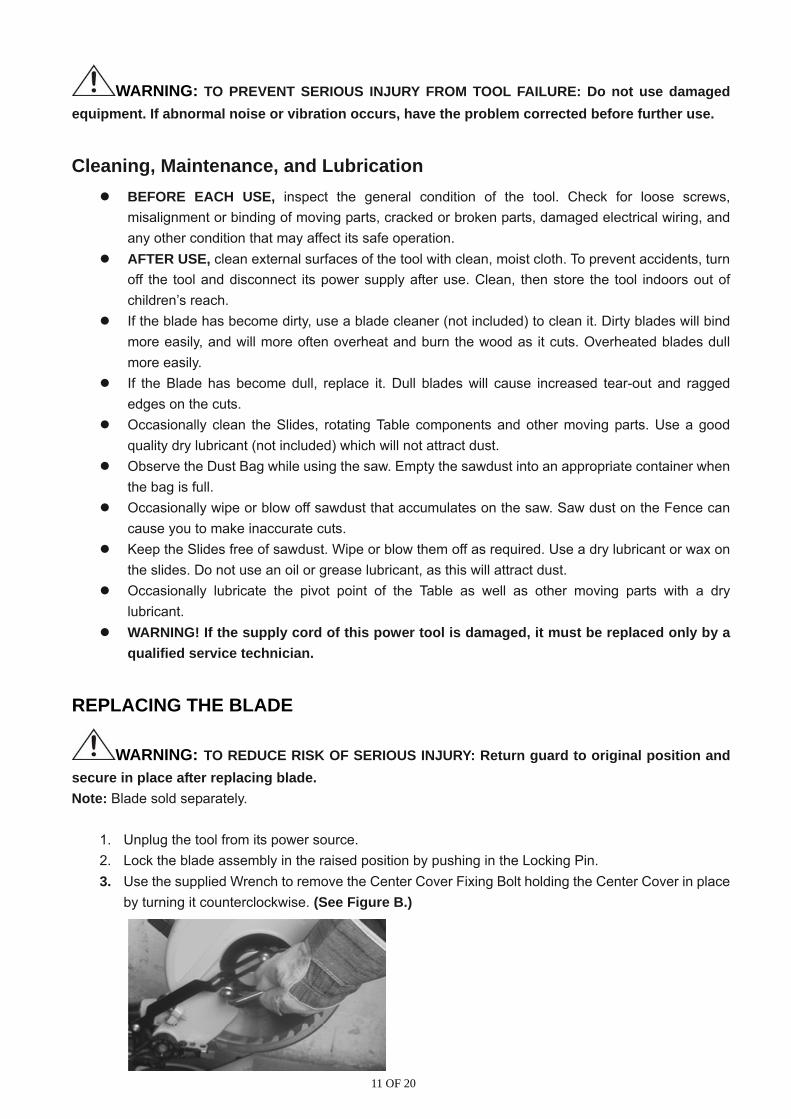
1. Unplug the tool from its power source. 2. Lock the blade assembly in the raised position by pushing in the Locking Pin. 3. Use the supplied Wrench to remove the Center Cover Fixing Bolt holding the Center Cover in place
by turning it counterclockwise. (See Figure B.)

12 OF 20
Figure B: Removing Bolt 4. Remove the Safety Screw. (See Figure C.)
Figure C: Removing Safety Screw 5. Raise the Blade Guard and Center Cover. (See Figure D.)
Figure D: Raise Blade Guard
6. While holding in the Arbor Lock Button, use the Wrench to loosen the Arbor Bolt by turning it clockwise. (See Figure E.)
Figure E: Arbor Bolt Note: The Arbor Bolt has a left hand thread, so it loosens by turning clockwise.
7. Remove the Arbor Bolt, Outer Flange and Saw Blade by pulling them straight off the Arbor. 8. Reinstall a new Blade on the Arbor.

13 OF 20
(See Figure F.) Be sure to match the direction marked on the new blade with the direction marked on the saw Blade Housing. Figure F: Removing Blade
9. Replace the Outer Flange and Arbor Bolt. Tighten the Arbor Bolt securely using the Wrench by turning it counterclockwise.
10. Rotate the Center Cover back into place and tighten the Center Cover Fixing Bolt using the Wrench by turning it clockwise. 11. Release the Locking Pin.
ADJUSTING THE FENCE The Fence holds the work piece in a fixed position while the Table and or the blade assembly are adjusted in a miter or bevel angle. To make accurate cuts, the Fence must be perpendicular (at a 90º angle) to the Saw Blade.
Before beginning work, make a test cut on scrap material with the Table set at 90º. Check the cut with an accurate square. You can also reverse the two pieces, hold the cut ends
together, and hold a good straight edge along the side of the pieces. If either test reveals that the cut is not a true 90º angle, you must adjust the Fence before
beginning work.
If Fence needs adjustment: First unplug the tool. Lower the blade assembly and lock it in place using the Locking Pin. Lay a carpenter’s square on the table with one edge along the blade and the other along the
Fence. Any inaccuracy should be visible. NOTE: The square must contact the surface of the blade, not the teeth, for an accurate reading.
The Fence is held in place with bolts at each end. Loosen the bolts slightly, and gently tap the Fence into position using a soft mallet. Retighten the bolts and make another test cut. Repeat the process until the Fence is adjusted accurately.
Once the Fence is accurately adjusted, tighten the bolts firmly in place. Recheck one last time, then proceed to work.
ADJUSTING THE MITER TABLE INDICATOR After you have checked or adjusted the fence to be sure it is at 90º to the Blade, check the accuracy of
the Miter Table Angle Indicator. Loosen the screw holding the Angle Indicator in place. Rotate it until the pointer is exactly on 90º. 4. Retighten the screw.
14 OF 20
ADJUSTING THE BEVEL ANGLE For making accurate cuts, the Saw Blade must be adjusted to be exactly vertical to the Table.
To check the angle, have the blade assembly in its normal upright position. Make a cut on a piece of flat sided, fairly thick scrap material.
Check the cut with an accurate square. The cut should be at exactly 90º. You can also check by rotating one cut-off piece 180º and hold the cut ends together. If the cut is not exactly vertical, the two pieces will form a slight angle.
If necessary, the bevel angle can be corrected by adjusting the Bevel Adjustment Screw on the right side under the Bevel Locking Lever.
Once the bevel angle is adjusted, adjust the Bevel Angle Indicator to read 0º when the Saw Blade is in the vertical position. Loosen the screw holding the Indicator in place, adjust it to be exactly over the 0º mark, then retighten the screw.
ADJUSTING OR REPLACING THE KERF BOARD If the Kerf Board becomes damaged it must be replaced.
Remove the four screws holding the Kerf Board in place. Install a new Kerf Board. Replace the four screws and tighten them slightly. To adjust the Kerf Board, lower the Saw Blade and lock it down with the Locking Pin. Adjust the
Kerf Board so the right side of the Blade slightly clears the edge of the Kerf Board. Loosen the Bevel Lock and set the Bevel Angle at 45º left. Ensure that the left side of the Blade clears the Kerf Board. Tighten the four screws holding the Kerf Board in place.

15 OF 20
TROUBLESHOOTING
Problem Possible Causes Likely Solutions
Tool will not start 1. No power at outlet. 2. Cord not connected.
1. Check power at outlet. 2. Check that cord is plugged in.
Tool operates sporadically or at low power
1. Low power supply or improper extension cords.
2. Worn or cracked Carbon Brushes.
1. Check power supply and power cords. 2. Check Carbon Brushes. Replace if
damaged or worn.
Wood burns at ends when cut
1. Dirty Blade. 2. Material is binding.
1. Clean Blade using blade cleaner or mineral spirits.
2. Check position of work material on Table. Material must be flat, flush against Fence and supported on ends.
Material frays or chips out.
1. Finished side is down. 2. Blade chipped or dull. 3. Blade inappropriate for
material. 4. Material is unsupported.
1. Keep finished side of material up or facing operator. Bottom and back side are prone to chip out.
2. Check for damaged teeth. Sharpen or replace blade.
3. Check blade manufacturer’s recommendations for material being cut. For cross cutting hard wood and for precision cuts use a thin kerf blade with 60 or more teeth.
4. Use a thin piece of scrap material, such as 1/4″plywood, underneath or behind the material to support the edges of the material as it is being cut.
Blade binds slowing or stopping saw.
1. Material is misaligned on the saw or ends are not supported.
2. Material is wet, contaminated or inappropriate blade is being used.
1. Material must be flat on table, flush against the fence and supported on both ends.
2. Check condition of material and check compatibility of blade to material.
WARNING: Follow all safety precautions whenever diagnosing or servicing the tool. Disconnect power supply before service.

16 OF 20
DIAGRAM

17 OF 20
PARTS LIST
No Name Pcs No Name Pcs1 Bolt M6x25 2 43 Lock Handle 1 2 Base 1 47 Bolt M5x14 2 3 Extension Arm 2 48 Bushing 1 4 Screw 2 49 Oil Cover 2 5 Foot 4 50 Bearing 3 6 Bolt M8x50 1 51 Rod 2 7 Bolt M5x10 4 52 Mount 1 8 Spring Washer 8 53 Line Button 2 9 Flat Washer 4 54 Washer 2 10 Plate 1 55 Bolt M6x10 4 11 Rub Slice 1 56 Limit Plate 1 12 Pin 1 57 Knob M6x20 1 13 Spring 1 58 Handle Ball 1 14 Pin 3x20 1 59 Lock Spring 1 15 Handle 1 60 Lock Pin 1 16 Plate 1 61 Spring Pin 1 17 Extend Pole 1 62 Cover stand 1 18 Pointer 1 63 Screw 1 19 Bolt M4x12 1 64 Bolt 1 20 Bolt M4x8 7 65 Washer 2 21 Kerf 1 66 Lock Button 1 22 Plate 1 67 Link Pole Bolt 2 23 Plate 1 68 Link Pole 1 24 Bolt M8x30 1 69 Brush Cover 2 25 Table 1 70 Carbon Brush 4 26 Flat Washer 1 71 Brush Handle 2 27 Lock Nut 1 72 Motor Housing 1 28 Rail 1 73 Bolt M6x30 4 29 Flat Washer 6 75 Stator 1 30 Spring Washer 6 76 Screw ST5x65 2 31 Bolt M6x25 2 77 Air Lock Circle 1 32 Screw 1 78 Bearing 1 33 Clamp 1 79 Rotor 1 34 Bolt 1 80 Bearing 1 35 Flat Washer 1 81 Lock Button 1 36 Pointer 1 82 Lock Button Spring 1 37 Nut 2 83 Spring 1 38 Spring 1 84 Pin 1 39 Bend Arm 1 85 Blade Cover 1 40 Flat Washer 2 86 Bolt M6x10 1 41 Lock Nut 1 87 Bolt M6x20 2
42 Washer 1 88 Dust Collector 1

18 OF 20
No Name Pcs No Name Pcs89 Dust Hood Knob 1 111 Blade Cover 1 90 Lock Washer 2 112 Link Pole Plank 1 91 Bearing 1 113 Switch 1 92 Spring Washer 1 114 Switch Spring 1 93 Gear 1 115 Switch Button 1 94 Front Cover 1 116 Handle Up Part 1 95 Bearing 1 117 Bolt ST4.2X18 4 96 Outer Axis 1 118 Handle 1 97 Key 4x13 1 119 Bolt ST6.3x25 2 98 Bearing Cover 1 120 Bolt M5x45 2 99 Bolt M5x18 3 121 Bolt ST4.2X14 2 100 Inner Flange 1 122 Bolt ST4.2X14 2 101 Blade (sold separately) 1 123 Press Plank 1 102 Outer Flange 1 124 Power Cord 1 103 Screw M8x20 Left 1 125 Rubber Sheath 1 104 Lock Nut 1 126 Terminal 1 105 Small Cover 1 127 Handle Down Part 1 106 Large Cover 1 128 Hex Key 1 107 Washer 1 129 Seal Ring 1 108 Bolt 1 109 Bolt M8x12 1 110 Blade Cover Spring 1 For technical questions and replacement parts, please call 1-800-222-5381.
19 OF 20
WARRANTY: Limited Warranty Northern Tool and Equipment Company, Inc. ("We'' or '"Us'') warrants to the original purchaser only ("You'' or “Your”) that the Ironton Power Tool product purchased will be free from material defects in both materials and workmanship, normal wear and tear excepted, for a period of one year from date of purchase. The foregoing warranty is valid only if the installation and use of the product is strictly in accordance with product instructions. There are no other warranties, express or implied, including the warranty of merchantability or fitness for a particular purpose. If the product does not comply with this limited warranty, Your sole and exclusive remedy is that We will, at our sole option and within a commercially reasonable time, either replace the product without charge to You or refund the purchase price (less shipping). This limited warranty is not transferable. Limitations on the Warranty This limited warranty does not cover: (a) normal wear and tear; (b) damage through abuse, neglect, misuse, or as a result of any accident or in any other manner; (c) damage from misapplication, overloading, or improper installation; (d) improper maintenance and repair; and (e) product alteration in any manner by anyone other than Us, with the sole exception of alterations made pursuant to product instructions and in a workmanlike manner. Obligations of Purchaser You must retain Your product purchase receipt to verify date of purchase and that You are the original purchaser. To make a warranty claim, contact Us at 1-800-222-5381, identify the product by make and model number, and follow the claim instructions that will be provided. The product and the purchase receipt must be provided to Us in order to process Your warranty claim. Any returned product that is replaced or refunded by Us becomes our property. You will be responsible for return shipping costs or costs related to Your return visit to a retail store. Remedy Limits Product replacement or a refund of the purchase price is Your sole remedy under this limited warranty or any other warranty related to the product. We shall not be liable for: service or labor charges or damage to Your property incurred in removing or replacing the product; any damages, including, without limitation, damage es to tangible personal property or personal injury, related to Your improper use, installation, or maintenance of the product; or any indirect, incidental or consequential damages of any kind for any reason. Assumption of Risk You acknowledge and agree that any use of the product for any purpose other than the specified use(s) stated in the product instructions is at Your own risk. Governing Law This limited warranty gives You specific legal rights, and You also may have other rights which vary from state to state. Some states do not allow limitations or exclusions on implied warranties or incidental or consequential damages, so the above limitations may not apply to You. This limited warranty is governed by the laws of the State of Minnesota, without regard to rules pertaining to conflicts of law. The state courts located in Dakota County, Minnesota shall have exclusive jurisdiction for any disputes relating to this warranty.

20 OF 20
WARNING Some dust created by power sanding, sawing, grinding, drilling, and other construction activities contains chemicals known to the State of California to cause cancer, birth defects or other reproductive harm. Some examples of these chemicals are: • Lead from lead-based paints, • Crystalline silica from bricks and cement and other masonry products, and • Arsenic and chromium from chemically treated lumber. Your risk from these exposures varies, depending on how often you do this type of work. To reduce your exposure to these chemicals: work in a well-ventilated area, and work with approved safety equipment, such as those dust masks that are specially designed to filter out microscopic particles.
Distributed by Northern Tool + Equipment Co., Inc.
Burnsville, Minnesota 55306 NorthernTool.com
Made in China