
10EC61 DIGITAL COMMUNICATION UNIT 3 - Ajay...
10
04-04-2017 1 DEPT. OF ECE, CEC 1 DIGITAL COMMUNICATION 10EC61 DEPT. OF ECE, CEC 2 • Waveform coding techniques (continued), DPCM, DM, applications. • Base-Band Shaping for Data Transmission • Discrete PAM signals, power spectra of discrete PAM signals. UNIT 3 OUTLINE REVIEW-SAMPLING TECHNIQUES DEPT. OF ECE, CEC 3 REVIEW- PCM TRANSMITTER 4.4 4.5 QUANTIZATION AND ENCODING OF A SAMPLED SIGNAL REDUNDANCY IN PULSE CODE MODULATION DEPT. OF ECE, CEC 6
Transcript of 10EC61 DIGITAL COMMUNICATION UNIT 3 - Ajay...

04-04-2017
1
DEPT. OF ECE, CEC 1
DIGITAL COMMUNICATION
10EC61
DEPT. OF ECE, CEC 2
• Waveform coding techniques (continued), DPCM, DM, applications.
• Base-Band Shaping for Data Transmission
• Discrete PAM signals, power spectra of discrete PAM signals.
UNIT 3 OUTLINE
REVIEW-SAMPLING TECHNIQUES
DEPT. OF ECE, CEC 3
REVIEW- PCM TRANSMITTER
4.4
4.5
QUANTIZATION AND ENCODING OF A SAMPLED SIGNAL REDUNDANCY IN PULSE CODE MODULATION
DEPT. OF ECE, CEC 6

04-04-2017
2
REDUNDANCY IN PCM….
DEPT. OF ECE, CEC 7
• Each sample is encoded independently of other samples.
• Samples of signals are highly correlated
• Signal doesn’t change fast
• We are taking the samples above Nyquist rate
• Correlated samples, when encoded, results in redundant information
• If the redundancy is removed before encoding, efficiency of the coded signal can be increased.
The redundancy can be eliminated by using DPCM
DPCM
DEPT. OF ECE, CEC 8
• Differential pulse code modulation (DPCM) is procedure of converting analog to
digital signal
• analog signal is sampled and then difference between actual sample value and
its predicted value is quantized and then encoded forming digital value.
• predicted value is based on previous sample or samples
• difference between samples can be interpreted as prediction error
• DPCM code words represent differences between samples unlike PCM where
code words represented a sample value.
DPCM TRANSMITTER
DEPT. OF ECE, CEC 9
DPCM RECEIVER
DEPT. OF ECE, CEC 10
PREDICTION GAIN ( GP)
DEPT. OF ECE, CEC 11
• The output signal-to-quantization noise ratio of a signal coder is defined as
-------------(1)
• where σx2 is the variance of the signal x(nTs) and σQ
2 is the variance of
the quantization error q(nTs). Then
------------(2)
• where σE2 is the variance of the prediction error e(nTs) and (SNR)P is the
prediction error-to-quantization noise ratio, defined by
----------------(3)
• The Prediction gain Gp is defined as
----------------(4)
DELTA MODULATION
DEPT. OF ECE, CEC 12
• If the sampling interval ‘Ts’ in DPCM is reduced considerably, i.e. if we sample a band
limited signal at a rate much faster than the Nyquist sampling rate, the adjacent samples
should have higher correlation
• The sample-to-sample amplitude difference will usually be very small.
• So, one may even think of only 1-bit quantization of the difference signal.
• The principle of Delta Modulation (DM) is based on this premise.
• Delta modulation is also viewed as a 1-bit DPCM scheme.
• The 1-bit quantizer is equivalent to a two-level comparator

04-04-2017
3
DELTA MODULATION
DEPT. OF ECE, CEC 13
DEPT. OF ECE, CEC 14
DM TRANSMITTER
DEPT. OF ECE, CEC 15
FEATURES OF DELTA MODULATION
DEPT. OF ECE, CEC 16
• No effective prediction unit – the prediction unit of a DPCM coder is eliminated and
replaced by a single-unit delay element.
• A 1-bit quantizer with two levels is used.
• The quantizer output simply indicates whether the present input sample is more or less
compared to its accumulated approximation.
• Output of the delay unit changes in small steps.
• The accumulator unit goes on adding the quantizer output with the previous
accumulated version
• Performance of the Delta Modulation scheme is dependent on the sampling rate.
DM RECEIVER
DEPT. OF ECE, CEC 17
ADVANTAGES OF DM
DEPT. OF ECE, CEC 18
• DM transmits only on bit for one sample. Thus the signalling rate and transmission
channel bandwidth is quite small for DM.
• Overall complexity of a delta modulator-demodulator is less compared to DPCM as the
predictor unit is absent in DM.
• One –bit code word for the o/p, which eliminates the need for word framing.

04-04-2017
4
DRAWBACKS OF DM
DEPT. OF ECE, CEC 19
• Two types of quantization error
• Slope-overload distortion
• Granular Noise
SLOPE-OVERLOAD DISTORTION
DEPT. OF ECE, CEC 20
• if the input signal amplitude changes fast, the step by-step accumulation process may
not catch up with the rate of change
• This happens initially when the demodulator starts operation from cold-start but is
usually of negligible effect for speech.
• However, if this phenomenon occurs frequently the quality of the received signal suffers.
• The received signal is said to suffer from slope-overload distortion.
• An intuitive remedy for this problem is to increase the step-size δ but that approach has
another serious problem (granular noise)
GRANULAR NOISE
DEPT. OF ECE, CEC 21
• If the step-size is made arbitrarily large to avoid slope-overload distortion, it may lead to
‘granular noise’.
• Imagine that the input speech signal is fluctuating but very close to zero over limited
time duration.
• During such moments, delta modulator is likely to produce a fairly long sequence of
101010…., reflecting that the accumulator output is close but alternating around the
input signal.
• This phenomenon is manifested at the output of the delta demodulator as a small but
perceptible noisy background.
• This is known as ‘granular noise’.
• Larger step-size increases the granular noise while smaller step size increases the
degree of slope-overload distortion.
ADAPTIVE DELTA MODULATION (ADM)
DEPT. OF ECE, CEC 22
ADM TRANSMITTER
DEPT. OF ECE, CEC 23
ADM RECEIVER
DEPT. OF ECE, CEC 24

04-04-2017
5
ADVANTAGES OF ADM
DEPT. OF ECE, CEC 25
• SNR is better than ordinary delta modulation because of the reduction in the slope
overload distortion and granular noise
• Utilization of bandwidth is better than DM
DIGITAL HIERARCHY (T1 TO T4 CARRIER SYSTEM)
DEPT. OF ECE, CEC 26
PICTURE PHONE
DEPT. OF ECE, CEC 27
• Bell Picturephone. It's Skype, 1964-style.
T1 FRAME
DEPT. OF ECE, CEC 28
T1 TRANSMISSION RATE
DEPT. OF ECE, CEC 29
T1 FRAME
DEPT. OF ECE, CEC 30
• In T1, the eight-bit digital samples created in the PCM step (for voice traffic only)
are grouped into the 24 discrete DS0 timeslots created by TDM.
• Each group of 24 timeslots is called a T1 frame.
• Since each timeslot contains eight bits, the number of information bits within each
frame totals 192 (24 x 8).
• Additionally, a 193rd bit is added to mark the end of one frame and the beginning of
the next.
• Appropriately enough, this added bit is called the framing bit.
• Since the DS0 signals are sampled 8,000 times per second, it means that 8,000
192-bit information frames are created during that period.
• Total: 1.536 Mb/s. At 8,000 samples per second, framing bits are created at the rate
of 8 kb/s.
• Result: a single 1.544 Mb/s signal known as digital signal-level one (DS1). See
Table 1 on how to calculate the 1.544 Mb/s rate.

04-04-2017
6
LIGHT WAVE TRANSMISSION
DEPT. OF ECE, CEC 31
DIGITAL MULTIPLEXERS
DEPT. OF ECE, CEC 32
Line Coding
33
Introduction:
•Binary Data: Pulses
•Line Coding: A pair of pulses to represent symbols 1 and 0
34
Properties of Line Coding:
•Transmission Bandwidth: as small as possible
• Power Efficiency: As small as possible for given BW and
probability of error
• Error Detection and Correction capability: Ex: Bipolar
• Favorable power spectral density: dc=0
• Adequate timing content: Extract timing from pulses
• Transparency: Prevent long strings of 0s or 1s 35
TYPES OF LINE CODING:
36
04-04-2017
7
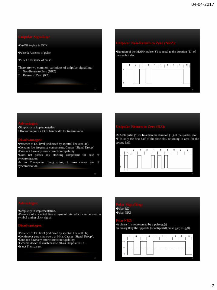
Unipolar Signaling:
•On-Off keying ie OOK
•Pulse 0: Absence of pulse
•Pulse1 : Presence of pulse
There are two common variations of unipolar signalling:
1. Non-Return to Zero (NRZ)
2. Return to Zero (RZ)
37
Unipolar Non-Return to Zero (NRZ):
•Duration of the MARK pulse (Ƭ ) is equal to the duration (To) of
the symbol slot.
38
Advantages: •Simplicity in implementation
• Doesn‟t require a lot of bandwidth for transmission.
Disadvantages: •Presence of DC level (indicated by spectral line at 0 Hz).
•Contains low frequency components. Causes “Signal Droop”
•Does not have any error correction capability.
•Does not posses any clocking component for ease of
synchronisation.
•Is not Transparent. Long string of zeros causes loss of
synchronisation.
39
Unipolar Return to Zero (RZ):
•MARK pulse (Ƭ ) is less than the duration (To) of the symbol slot.
•Fills only the first half of the time slot, returning to zero for the
second half.
40
Advantages: •Simplicity in implementation. •Presence of a spectral line at symbol rate which can be used as symbol timing clock signal.
Disadvantages: •Presence of DC level (indicated by spectral line at 0 Hz). •Continuous part is non-zero at 0 Hz. Causes “Signal Droop”. •Does not have any error correction capability. •Occupies twice as much bandwidth as Unipolar NRZ. •Is not Transparent
41
Polar Signalling: •Polar RZ
•Polar NRZ
Polar NRZ:
•A binary 1 is represented by a pulse g1(t)
•A binary 0 by the opposite (or antipodal) pulse g0(t) = -g1(t).
42

04-04-2017
8
Advantages: •Simplicity in implementation.
•No DC component.
Disadvantages: •Continuous part is non-zero at 0 Hz. Causes “Signal Droop”.
•Does not have any error correction capability.
•Does not posses any clocking component for ease of
synchronisation.
•Is not transparent.
43
Polar RZ:
•A binary 1: A pulse g1(t)
•A binary 0: The opposite (or antipodal) pulse g0(t) = -g1(t).
•Fills only the first half of the time slot, returning to zero for the
second half.
44
Advantages: •Simplicity in implementation.
•No DC component.
Disadvantages: •Continuous part is non-zero at 0 Hz. Causes “Signal Droop”.
•Does not have any error correction capability.
•Occupies twice as much bandwidth as Polar NRZ.
45
Bipolar Signalling:
•Alternate mark inversion (AMI)
•Uses three voltage levels (+V, 0, -V)
•0: Absence of a pulse
•1: Alternating voltage levels of +V and –V
46
Bipolar NRZ:
Bipolar RZ:
47
Advantages: •No DC component.
•Occupies less bandwidth than unipolar and polar NRZ schemes.
•Does not suffer from signal droop (suitable for transmission over
AC coupled lines).
•Possesses single error detection capability.
Disadvantages: •Does not posses any clocking component for ease of
synchronisation.
•Is not Transparent.
48

04-04-2017
9
Manchester Signalling:
•The duration of the bit is divided into two halves
•A „One‟ is +ve in 1st half and -ve in 2nd half.
•A „Zero‟ is -ve in 1st half and +ve in 2nd half.
49
Advantages: •No DC component.
•Does not suffer from signal droop (suitable for transmission over
AC coupled lines).
•Easy to synchronise.
•Is Transparent.
Disadvantages: •Because of the greater number of transitions it occupies a
significantly large bandwidth.
•Does not have error detection capability.
50
Power Spectral Density: •The function which gives distribution of power of a signal at
various frequencies in frequency domain.
•PSD is the Fourier Transform of autocorrelation
•Rectangular pulse and its spectrum
51
PSD Derivation: • We now need to derive the time autocorrelation of a power
signal x(t)
_--
• Since x(t) consists of impulses, is found by
• Recognizing for real signals, we have
52
•Since the pulse filter has the spectrum of , we have
• Now, we can use this to find the PSD of various line codes.
53
PSD of Polar Signalling: • In polar signalling,
Binary “1” is transmitted by a pulse f(t)
Binary “0” is transmitted by a pulse –f(t)
• In this case, is equally likely to be 1 or -1 and is always 1.
• Moreover, both and are either 1 or -1. So, is either 1
or -1. They are equally likely to be 1 or -1 on the average, out of N terms the product
is equal to 1 for N/2 terms and is equal to -1 for the remaining N/2 terms.
Where, There are N pulses and for each one.
The summation on the right-hand side of the above equation is N.
54

04-04-2017
10
PSD of Bipolar Signalling:
•To calculate the PSD, we have
•On the average, half of the are 0, and the remaining half are
either 1 or -1, with . Therefore,
55
•To compute R1, we consider the pulse strength product .
-Four possible equally likely sequences of two bits:11,10,01,00.
-Since bit 0 encoded by no pulse , the product for
the last three of these sequences. This means that, on the average,
3N/4 combinations have and only N/4 combinations have
non zero . Because of the bipolar rule, the bit sequence 11
can only be encoded by two consecutive pulse of opposite
polarities. This means the product for the N/4
combinations.
56
PSD of Lines Codes:
57
Sr.
No.
Parameters Polar RZ Polar NRZ AMI Manchester
1 Transmission of DC
component
YES YES NO NO
2 Signaling Rate 1/Tb 1/Tb 1/Tb 1/Tb
3 Noise Immunity LOW LOW HIGH HIGH
4 Synchronizing
Capability
Poor Poor Very Good Very Good
5 Bandwidth Required 1/Tb 1/2Tb 1/2Tb 1/Tb
6 Crosstalk HIGH HIGH LOW LOW
Comparison of Line Codes:
58


![Ece Vi Digital Communication [10ec61] Notes](https://static.fdocuments.in/doc/165x107/55cf9d54550346d033ad2661/ece-vi-digital-communication-10ec61-notes.jpg)

