109000002 ALP GB - Oleotecna · PHC / PHCI 1200-EU PHC / PHCI 1100-EU PHC / PHCI 940-EU PHC / PHCI...
36
Operating manual ALP-Passenger lifts Translation based on the original German version! Document no. 109000002 Every operator, before he places the device in service, must read the operating manual!
Transcript of 109000002 ALP GB - Oleotecna · PHC / PHCI 1200-EU PHC / PHCI 1100-EU PHC / PHCI 940-EU PHC / PHCI...
Operating manual
ALP-Passenger lifts
Translation based on the original German version!
Document no. 109000002 Every operator, before he places the device in service, must read the operating manual!

ALP-Passenger lifts
2 109000002
© Böcker Maschinenwerke GmbH Lippestr. 69 - 73 D-59368 Werne Tel.: +49 (0) 2389 / 7989-0 Fax: +49 (0) 2389 / 7989-9000 E-Mail: [email protected] Internet: www.boecker-group.com
ALP-Passenger lifts
109000002 3
Assignment of these operating instructions
These assembly and operating instructions ...
Document no.: 109000002
Original to: 09/2006
Version: 12032014
... applies to:
Type: PH / PHI 1400-EU PH / PHI 1300-EU PH / PHI 1200-EU PH / PHI 1100-EU PH / PHI 900-EU PH / PHI 760-EU PHC / PHCI 1200-EU PHC / PHCI 1100-EU PHC / PHCI 940-EU PHC / PHCI 800-EU PHC / PHCI 650 EU
ALP-Passenger lifts
4 109000002
1 Introduction ....................................................................................................................... 6
2 Description ........................................................................................................................ 7
3 Transport ........................................................................................................................... 8
3.1 Forklift transport ............................................................................................................ 9
4 Stabile set up................................................................................................................... 10
4.1 Extension arm use ...................................................................................................... 13
4.2 Halfen anchoring systems ........................................................................................... 13
5 Start up ............................................................................................................................ 14
6 Handling .......................................................................................................................... 15
7 Operating the lift ............................................................................................................. 17
7.1 Two-handed operation ................................................................................................ 18
7.2 Foot operation ............................................................................................................. 18
7.3 Operation from the switch box .................................................................................... 19
8 Unauthorized use ............................................................................................................ 20
9 Emergency lowering ....................................................................................................... 21
10 Additional lowering ....................................................................................................... 22
11 Working on electrical facilities ..................................................................................... 23
12 Lift models ..................................................................................................................... 24
12.1 Battery/Batteries in the case ..................................................................................... 25
12.2 Batteries in the chassis frame ................................................................................... 25
13 Supervision of the safety facilities / Regulations requiring compliance ................... 26
14 Maintenance and inspection ........................................................................................ 28
14.1 Excerpt from the TRADE ASSOCIATION Policy BGG 945 Point 5.4........................ 29
14.2 Excerpt from the TRADE ASSOCIATION Policy BGG 945 Point 5.3........................ 29
15 Conduct in the Event of Disruption ............................................................................. 30
16 Replacement Parts ........................................................................................................ 31
17 Technical Data ............................................................................................................... 32
18 Special equipment and accessories ............................................................................ 34
18.1 Additional operation from below ................................................................................ 34
18.2 Passenger / Load switching (Photo 26) ..................................................................... 34

ALP-Passenger lifts
109000002 5
19 Safety regulations ......................................................................................................... 35
20 Index .............................................................................................................................. 36
Boecker Titel @ 8\mod_1141294717732_1.doc @ 72281
Pos : 1.3 /F I/. ... .... .. Seitenumbr uch .. ... ... .. @ 0\mod272_1.doc @ 1522

ALP-Passenger lifts
Introduction
6 109000002
Pos : 1.4 /F I/Allgemei nes /1 Allgemeines Ti tel @ 0\mod155_1.doc @ 2732
1 Introduction Pos : 1.5 /Kothes! Networ k/Boeker/Allgemei nes/Infor mationen zur Betriebsanl eitung Böcker @ 7\mod_1140875004052_1.doc @ 71243
The “Guidelines 2006/42/EG” and the EN280-2001 provide the basis for the set-up and handling of this working platform. Since the constructive design of the working platform is executed on the basis of EN280, reference is additionally made in the following Operating Instructions to the corresponding passages.
Pos : 1.8 /F I/ ----------Absatzende----------- @ 3\mod_1120132332937_1.doc @ 17416 Pos : 1.31 /FI/ ----------Absatzende----------- @ 3\mod_1120132332937_1.doc @ 17416
Pos : 2.1 /F I/. ... .... .. Seitenumbr uch .. ... ... .. @ 0\mod272_1.doc @ 1522
ALP-Passenger lifts
Description
109000002 7
Pos : 2.2 /F I/Sicherheit/1 Sicherheit Titel @ 4\mod_1123592830376_1.doc @ 19886
2 Description Pos : 2.3 /Kothes! Networ k/Boeker/Sicher heit /Allgemeiner T ext Sicher hei t Boecker @ 8\mod_1141813939045_1.doc @ 74731
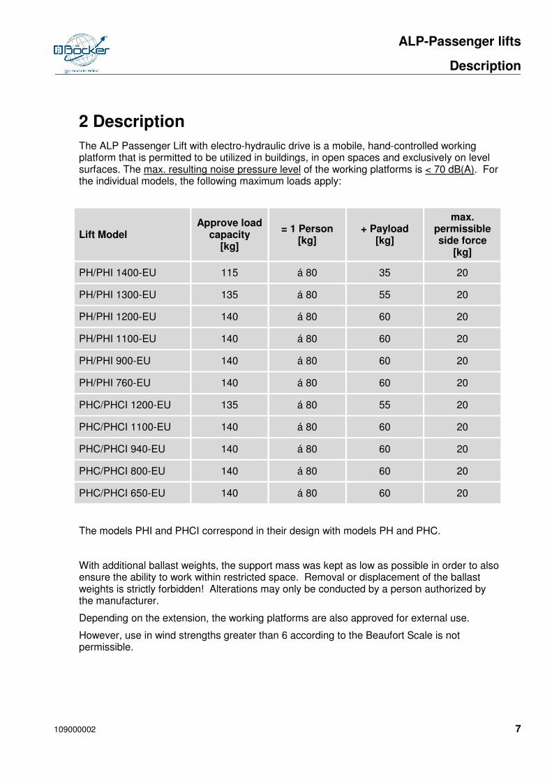
The ALP Passenger Lift with electro-hydraulic drive is a mobile, hand-controlled working platform that is permitted to be utilized in buildings, in open spaces and exclusively on level surfaces. The max. resulting noise pressure level of the working platforms is < 70 dB(A). For the individual models, the following maximum loads apply:
Lift Model Approve load
capacity [kg]
= 1 Person [kg]
+ Payload [kg]
max. permissible side force
[kg]
PH/PHI 1400-EU 115 á 80 35 20
PH/PHI 1300-EU 135 á 80 55 20
PH/PHI 1200-EU 140 á 80 60 20
PH/PHI 1100-EU 140 á 80 60 20
PH/PHI 900-EU 140 á 80 60 20
PH/PHI 760-EU 140 á 80 60 20
PHC/PHCI 1200-EU 135 á 80 55 20
PHC/PHCI 1100-EU 140 á 80 60 20
PHC/PHCI 940-EU 140 á 80 60 20
PHC/PHCI 800-EU 140 á 80 60 20
PHC/PHCI 650-EU 140 á 80 60 20
The models PHI and PHCI correspond in their design with models PH and PHC.
With additional ballast weights, the support mass was kept as low as possible in order to also ensure the ability to work within restricted space. Removal or displacement of the ballast weights is strictly forbidden! Alterations may only be conducted by a person authorized by the manufacturer.
Depending on the extension, the working platforms are also approved for external use.
However, use in wind strengths greater than 6 according to the Beaufort Scale is not permissible.
Pos : 2.4 /F I/(---------- 1 Leerzeile ----------) @ 0\mod796_1.doc @ 1527 Pos : 3.1 /F I/. ... .... .. Seitenumbr uch .. ... ... .. @ 0\mod272_1.doc tenumbr uch .. ... ... .. @ 0\mod272_1.doc @ 1522

ALP-Passenger lifts
Transport
8 109000002
Pos : 3.3 /F I/T echnische Daten/1 T echni sche D aten Titel @ 0\mod253_1.doc @ 2907
3 Transport
The ALP Passenger Lift can be transported in vehicles or on trailers, in both a lying or standing position. When transporting in a lying position, the Rail Guard (Photo 1) must always be fully secured into position. Otherwise the rails fall apart from one another; additionally, the Tank Ventilation Valve (Photo 2) must always be closed to prevent the hydraulic oil from seeping out.
Photo 1 Photo 2
Lift Model PHCI can only be transported in a standing position. Lift Model PH 1400/PHI 1400 must always be handled by 2 persons.
The PH/PHC working platforms are unloaded with the assistance of the standard equipment telescopic tilting device from the vehicle or trailer (also applies for loading), (Photo 3 & 4); The PHCI model should be loaded and unloaded using a loading ramp.
We recommend also using a loading ramp for the models, PH 1200/1300/1400 and PHI.
Photo 3 Photo 4
ALP-Passenger lifts
Transport
109000002 9
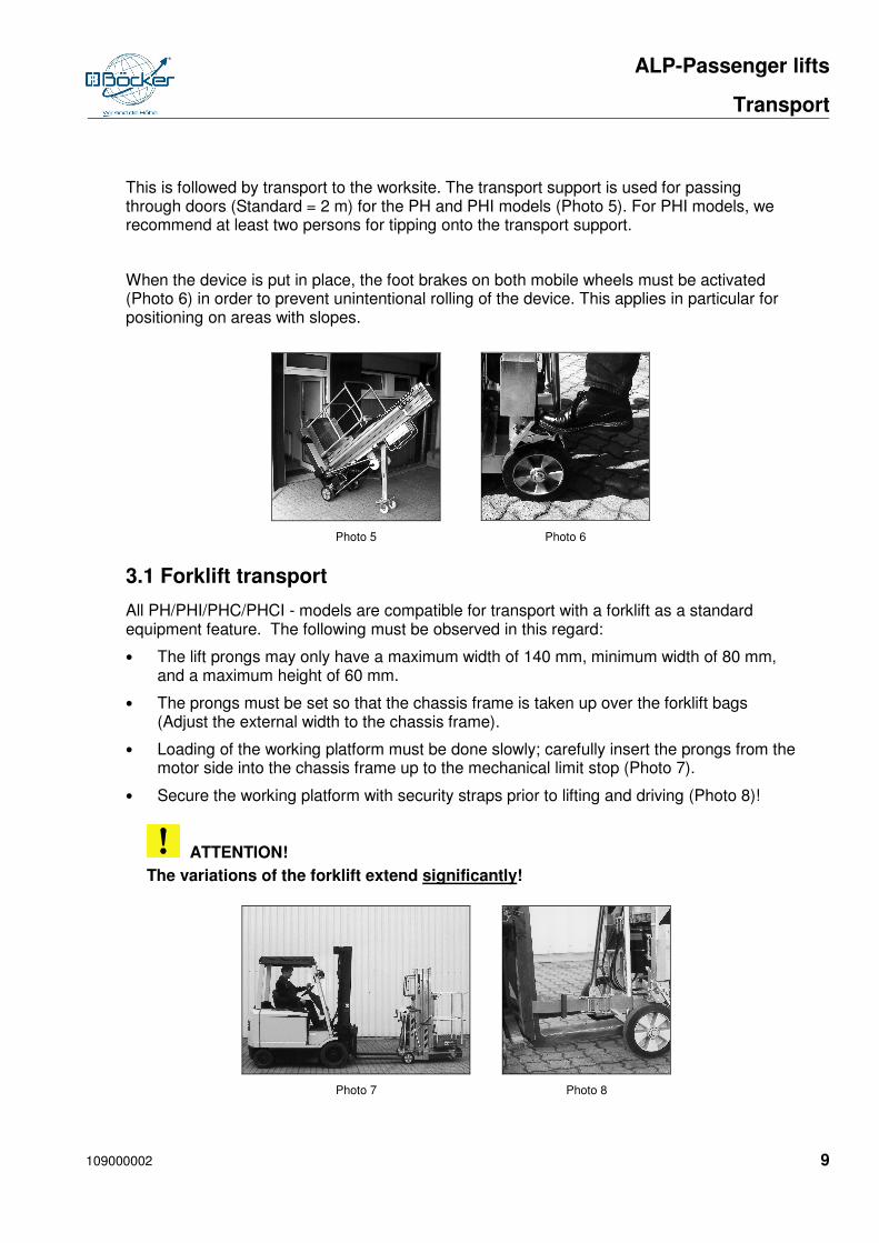
This is followed by transport to the worksite. The transport support is used for passing through doors (Standard = 2 m) for the PH and PHI models (Photo 5). For PHI models, we recommend at least two persons for tipping onto the transport support.
When the device is put in place, the foot brakes on both mobile wheels must be activated (Photo 6) in order to prevent unintentional rolling of the device. This applies in particular for positioning on areas with slopes.
Photo 5 Photo 6
3.1 Forklift transport
All PH/PHI/PHC/PHCI - models are compatible for transport with a forklift as a standard equipment feature. The following must be observed in this regard:
• The lift prongs may only have a maximum width of 140 mm, minimum width of 80 mm, and a maximum height of 60 mm.
• The prongs must be set so that the chassis frame is taken up over the forklift bags (Adjust the external width to the chassis frame).
• Loading of the working platform must be done slowly; carefully insert the prongs from the motor side into the chassis frame up to the mechanical limit stop (Photo 7).
• Secure the working platform with security straps prior to lifting and driving (Photo 8)!
ATTENTION!
The variations of the forklift extend significantly!
Photo 7 Photo 8

ALP-Passenger lifts
Stabile set up
10 109000002
4 Stabile set up
1) This working platform is to be set up in accordance with the Operating Instructions in such way that there are no squeezing or pinching points between the lift platform and parts of the surrounding area, and such that with proper operation the activities to be conducted on the loading facilities or in the event of a load can be carried out without impairment.
2) The permissible ground load is to be observed in the proper set up and start-up of this working platform.
WARNING!
The permissible ground load may not be exceeded.
3) Working platforms set up or extending into the traffic space of vehicles are to be safeguarded against the traffic hazards in an appropriate manner.
The extension arms must be attached at the worksite. For this, the following is possible:
a) Standard Arrangement: Use only with uniform extension arm length (Photo 9).
Photo 9
Permissible for external and internal use!
For internal and external use, there are fundamentally varying extension arm lengths for each respective working platform. If operation of the working platform for internal and external use (with wind load) is permissible, the Operator must first ascertain what extension arm length is needed for the assignment type (ABSOLUTELY REQUIRED!). This can be gathered from the following chart or the Inspection Book which is to accompany the device at all times. “Mixing” the extension arms is impermissible for such assignment types!

ALP-Passenger lifts
Stabile set up
109000002 11
Lift Model Extension Arm Length
INTERNAL [mm] Extension Arm Length
EXTERNAL [mm]
PH 1400-EU 1210 2305
PH 1300-EU 1140 2150
PH 1200-EU 1140 2115
PH 1100-EU 900 1760
PH 900-EU 715 1500
PH 760-EU 635 1210
PHC 1200-EU 1050 2115
PHC 1100-EU 850 1880
PHC 940-EU 715 1550
PHC 800-EU 635 1300
PHC 650-EU 535 1050
PHI 1400-EU 1050 2115
PHI 1300-EU 900 1835
PHI 1200-EU 915 1835
PHI 1100-EU 715 1500
PHI 900-EU 535 1300
PHI 760-EU 535 1050
PHCI 1200-EU 765 1835
PHCI 1100-EU 635 1575
PHCI 940-EU 535 1300
PHCI 800-EU 535 1050
PHCI 650-EU 535 1050
ALP-Passenger lifts
Stabile set up
12 109000002
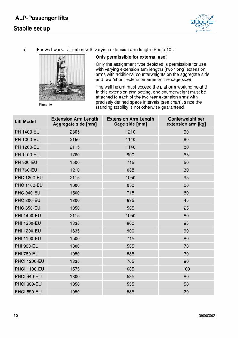
b) For wall work: Utilization with varying extension arm length (Photo 10).
Photo 10
Only permissible for external use!
Only the assignment type depicted is permissible for use with varying extension arm lengths (two “long” extension arms with additional counterweights on the aggregate side and two “short” extension arms on the cage side)!
The wall height must exceed the platform working height! In this extension arm setting, one counterweight must be attached to each of the two rear extension arms with precisely defined space intervals (see chart), since the standing stability is not otherwise guaranteed.
Lift Model Extension Arm Length Aggregate side [mm]
Extension Arm Length Cage side [mm]
Conterweight per extension arm [kg]
PH 1400-EU 2305 1210 90
PH 1300-EU 2150 1140 80
PH 1200-EU 2115 1140 80
PH 1100-EU 1760 900 65
PH 900-EU 1500 715 50
PH 760-EU 1210 635 30
PHC 1200-EU 2115 1050 95
PHC 1100-EU 1880 850 80
PHC 940-EU 1500 715 60
PHC 800-EU 1300 635 45
PHC 650-EU 1050 535 25
PHI 1400-EU 2115 1050 80
PHI 1300-EU 1835 900 95
PHI 1200-EU 1835 900 90
PHI 1100-EU 1500 715 80
PHI 900-EU 1300 535 70
PHI 760-EU 1050 535 30
PHCI 1200-EU 1835 765 90
PHCI 1100-EU 1575 635 100
PHCI 940-EU 1300 535 80
PHCI 800-EU 1050 535 50
PHCI 650-EU 1050 535 20
ALP-Passenger lifts
Stabile set up
109000002 13
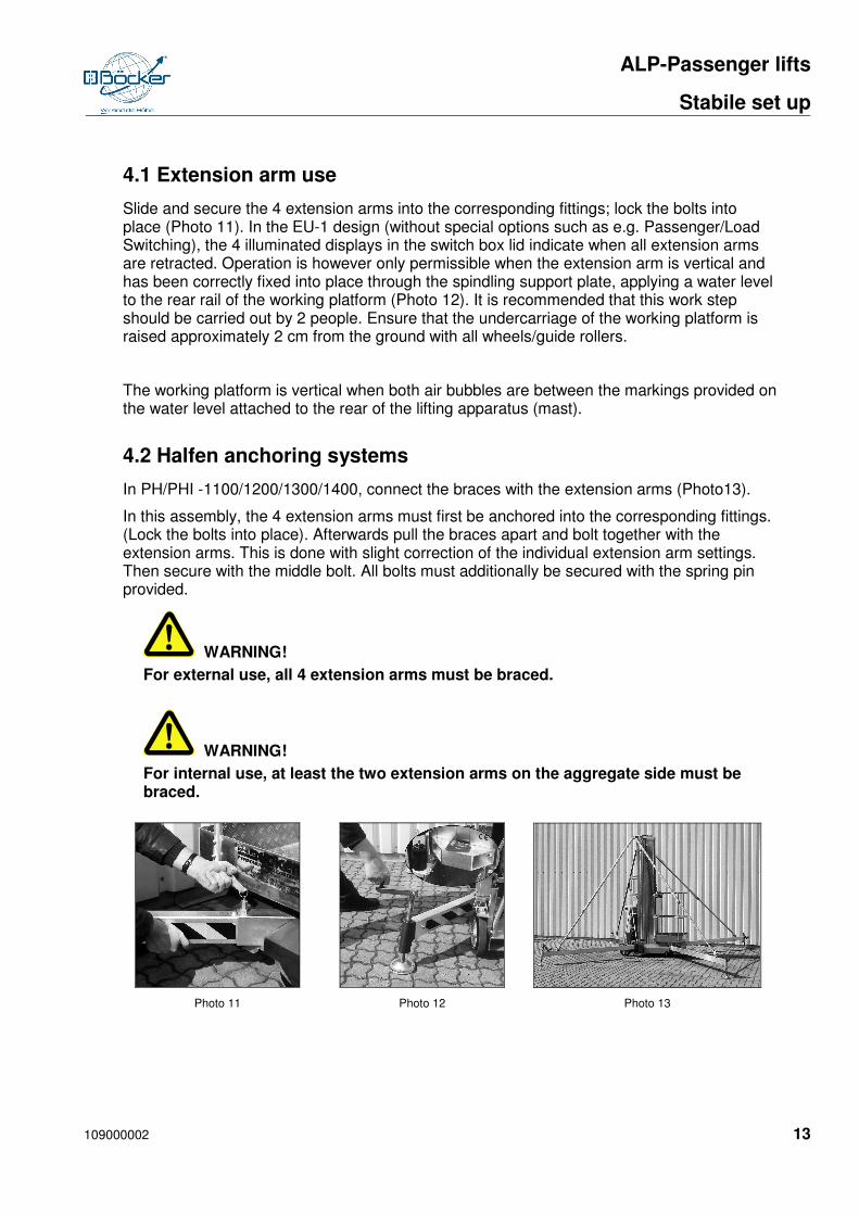
4.1 Extension arm use
Slide and secure the 4 extension arms into the corresponding fittings; lock the bolts into place (Photo 11). In the EU-1 design (without special options such as e.g. Passenger/Load Switching), the 4 illuminated displays in the switch box lid indicate when all extension arms are retracted. Operation is however only permissible when the extension arm is vertical and has been correctly fixed into place through the spindling support plate, applying a water level to the rear rail of the working platform (Photo 12). It is recommended that this work step should be carried out by 2 people. Ensure that the undercarriage of the working platform is raised approximately 2 cm from the ground with all wheels/guide rollers.
The working platform is vertical when both air bubbles are between the markings provided on the water level attached to the rear of the lifting apparatus (mast).
4.2 Halfen anchoring systems
In PH/PHI -1100/1200/1300/1400, connect the braces with the extension arms (Photo13).
In this assembly, the 4 extension arms must first be anchored into the corresponding fittings. (Lock the bolts into place). Afterwards pull the braces apart and bolt together with the extension arms. This is done with slight correction of the individual extension arm settings. Then secure with the middle bolt. All bolts must additionally be secured with the spring pin provided.
WARNING!
For external use, all 4 extension arms must be braced.
WARNING!
For internal use, at least the two extension arms on the aggregate side must be braced.
Photo 11 Photo 12 Photo 13
ALP-Passenger lifts
Start up
14 109000002
5 Start up
ATTENTION!
Before start-up, unbolt the carriage * and open the Tank Ventilation Valve!
The Rail Guard is pulled out, turned toward the rear and sunk into the last rail (excluded PHC-HI). The Tank Ventilation Valve must be opened during operation; otherwise the hydraulic system will be damaged (pump, seals). Ensure that the working platform receives sufficient electricity. Attention! Excessively long electrical lines or too many consumers can lead to disruptions and/or to defects in working platform. After connection to the electricity supply, set the key switch on the Switch Box Function. Make the electrical connection with the supply network using a residual current circuit breaker or small size current distributor.
*Unbolting not necessary with PHCI
ALP-Passenger lifts
Handling
109000002 15
6 Handling
Utilize the ALP Passenger Lift only on even surfaces with a firm underground, and never overload. Never push the device when it is extended. Elevating of the passenger & payload takes place via an electro-hydraulic drive. Important! Before work starts with the ALP Passenger Lift, the Operator must become acquainted with the device and be precisely briefed.
From 2014 production year onwards, the ALP personnel lifts PH/PHI/PHC/PHCI/PHCHI ….EU are fitted with an anchorage point (clunk - click) for the personal safety equipment of the user. This equipment is not absolutely necessary for the operation of the lift, but it is recommended!
ATTENTION! If however, safety regulations have been issued by the employer for the use of personal safety equipment when using the ALP personnel lifts, the following applies:
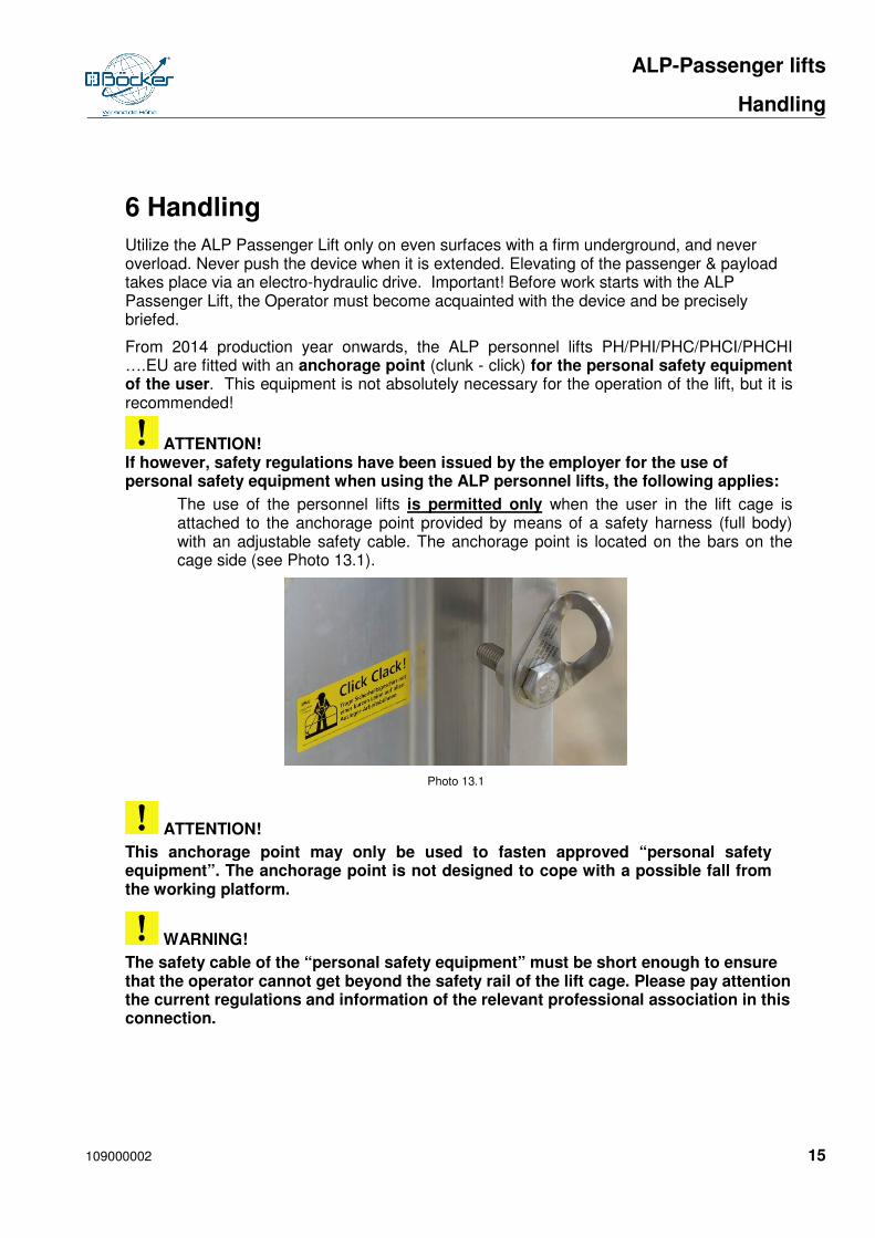
The use of the personnel lifts is permitted only when the user in the lift cage is attached to the anchorage point provided by means of a safety harness (full body) with an adjustable safety cable. The anchorage point is located on the bars on the cage side (see Photo 13.1).
Photo 13.1
ATTENTION!
This anchorage point may only be used to fasten approved “personal safety equipment”. The anchorage point is not designed to cope with a possible fall from the working platform.
WARNING!
The safety cable of the “personal safety equipment” must be short enough to ensure that the operator cannot get beyond the safety rail of the lift cage. Please pay attention the current regulations and information of the relevant professional association in this connection.
ALP-Passenger lifts
Handling
16 109000002
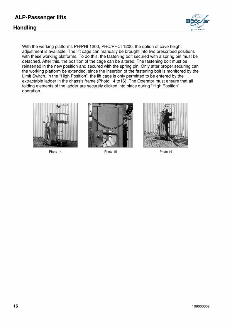
With the working platforms PH/PHI 1200, PHC/PHCI 1200, the option of cave height adjustment is available. The lift cage can manually be brought into two prescribed positions with these working platforms. To do this, the fastening bolt secured with a spring pin must be detached. After this, the position of the cage can be altered. The fastening bolt must be reinserted in the new position and secured with the spring pin. Only after proper securing can the working platform be extended, since the insertion of the fastening bolt is monitored by the Limit Switch. In the “High Position”, the lift cage is only permitted to be entered by the extractable ladder in the chassis frame (Photo 14 to16). The Operator must ensure that all folding elements of the ladder are securely clicked into place during “High Position” operation.
Photo 14 Photo 15 Photo 16
ALP-Passenger lifts
Operating the lift
109000002 17
7 Operating the lift
ATTENTION!
If safety instructions or regulations have been issued by the employer for the use of personal safety equipment when operating ALP personnel lifts, the anchorage eye (see Para 6 Operation) is to be used.
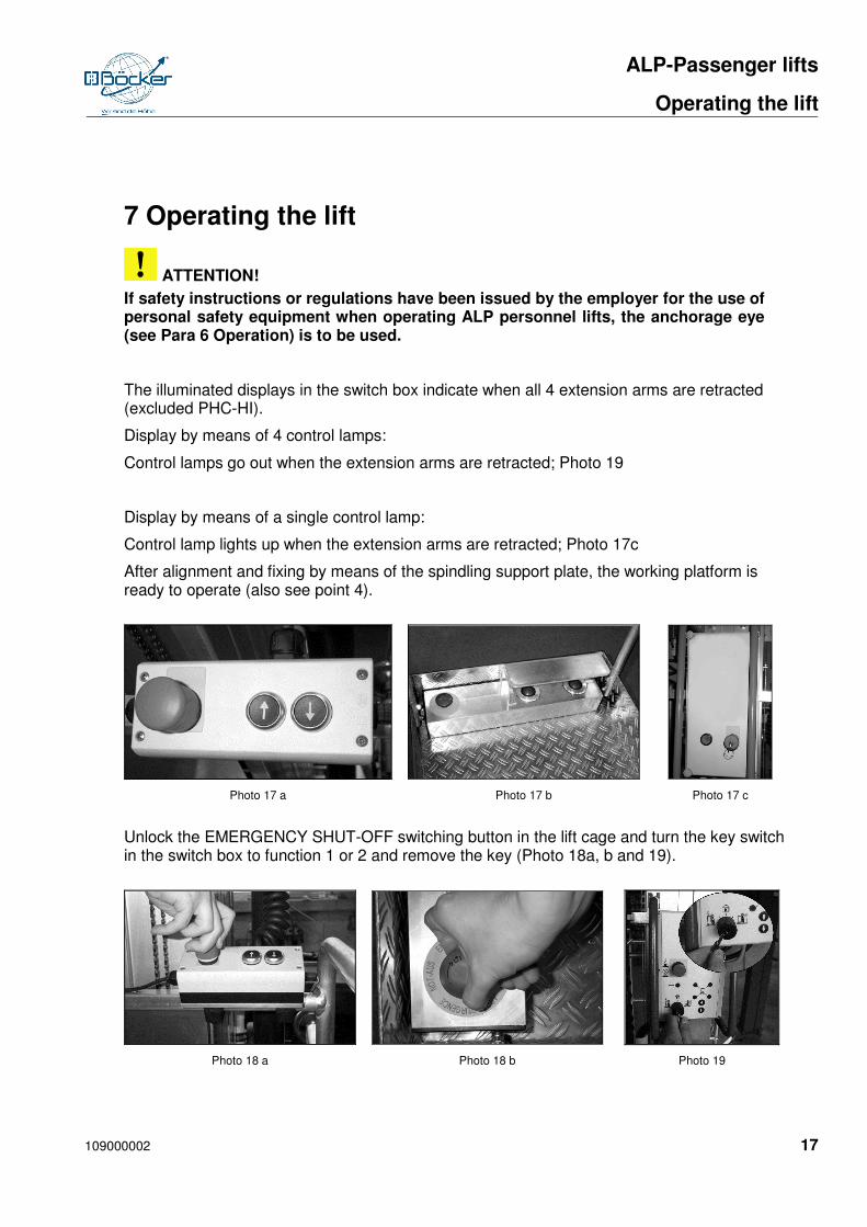
The illuminated displays in the switch box indicate when all 4 extension arms are retracted (excluded PHC-HI).
Display by means of 4 control lamps:
Control lamps go out when the extension arms are retracted; Photo 19
Display by means of a single control lamp:
Control lamp lights up when the extension arms are retracted; Photo 17c
After alignment and fixing by means of the spindling support plate, the working platform is ready to operate (also see point 4).
Photo 17 a Photo 17 b Photo 17 c
Unlock the EMERGENCY SHUT-OFF switching button in the lift cage and turn the key switch in the switch box to function 1 or 2 and remove the key (Photo 18a, b and 19).
Photo 18 a Photo 18 b Photo 19
ALP-Passenger lifts
Operating the lift
18 109000002
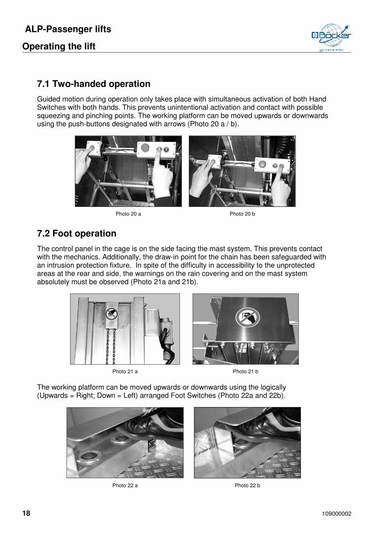
7.1 Two-handed operation
Guided motion during operation only takes place with simultaneous activation of both Hand Switches with both hands. This prevents unintentional activation and contact with possible squeezing and pinching points. The working platform can be moved upwards or downwards using the push-buttons designated with arrows (Photo 20 a / b).
Photo 20 a Photo 20 b
7.2 Foot operation
The control panel in the cage is on the side facing the mast system. This prevents contact with the mechanics. Additionally, the draw-in point for the chain has been safeguarded with an intrusion protection fixture. In spite of the difficulty in accessibility to the unprotected areas at the rear and side, the warnings on the rain covering and on the mast system absolutely must be observed (Photo 21a and 21b).
Photo 21 a Photo 21 b
The working platform can be moved upwards or downwards using the logically (Upwards = Right; Down = Left) arranged Foot Switches (Photo 22a and 22b).
Photo 22 a Photo 22 b

ALP-Passenger lifts
Operating the lift
109000002 19
7.3 Operation from the switch box
In the event of an additional steering mechanism in the Switch Box, operation at the Switch Box by means of the lockable switch can be selected. For this it must be ensured that switching can only be conducted under control of the operator. For this, the key for the switch must be removed prior to operation after the desired operating position has been selected (also see Point 18).
WARNING!
Operation must be stopped in wind strengths exceeding 6 according to the Beaufort Scale!
The preset platform lowering speed can be obtained from the Inspection Book! It may not be manipulated in any way.

ALP-Passenger lifts
Unauthorized use
20 109000002
8 Unauthorized use
Upon leaving the working platform, the EMERGENCY SHUT-OFF switch in the Switch Box must be activated and the key removed in order to safeguard the working platform against unauthorized use.
ALP-Passenger lifts
Emergency lowering
109000002 21
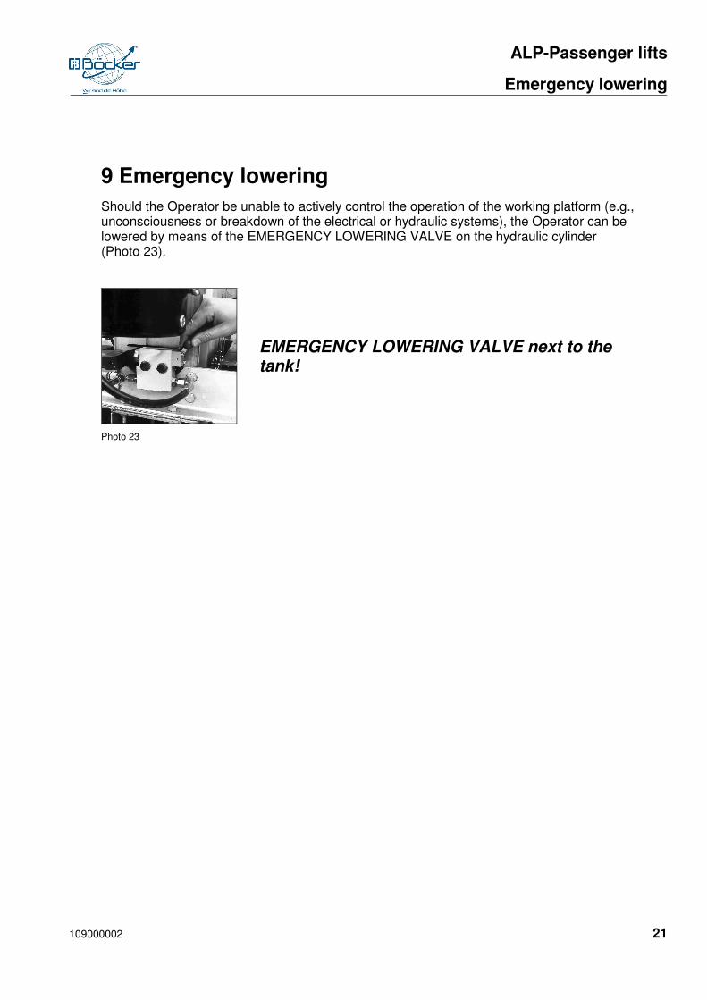
9 Emergency lowering
Should the Operator be unable to actively control the operation of the working platform (e.g., unconsciousness or breakdown of the electrical or hydraulic systems), the Operator can be lowered by means of the EMERGENCY LOWERING VALVE on the hydraulic cylinder (Photo 23).
EMERGENCY LOWERING VALVE next to the
tank!
Photo 23

ALP-Passenger lifts
Additional lowering
22 109000002
10 Additional lowering
All EU-1 standard devices have an additional lowering possibility in the event of disruption of the electrical supply. The working platform can be lowered by the Operator in the cage via an automatically charging battery (in the Switch Box).

ALP-Passenger lifts
Working on electrical facilities
109000002 23
11 Working on electrical facilities
The ALP Passenger Lifts are not suitable for work on electrically conductive parts. (Unprotected electrical facilities). Take great care with wires, overhead lines, and floor extensions. Maintain a minimum distance of 5 meters with overhead lines.
ALP-Passenger lifts
Lift models
24 109000002
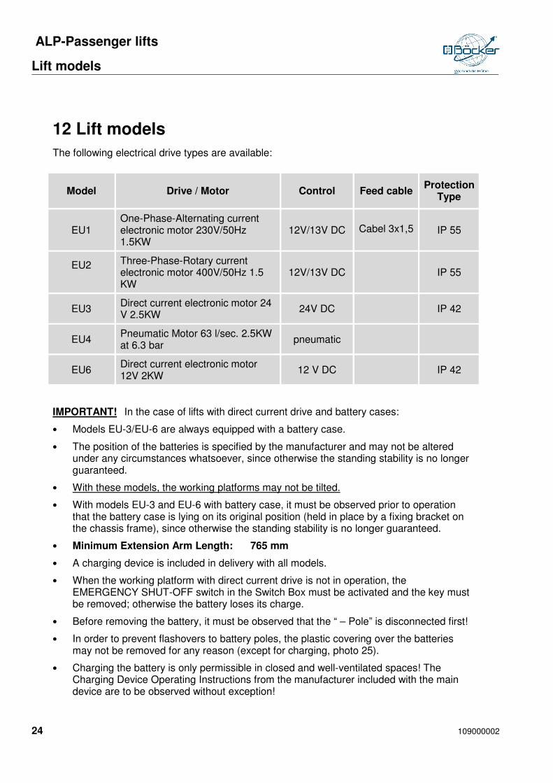
12 Lift models
The following electrical drive types are available:
Model Drive / Motor Control Feed cable Protection
Type
EU1 One-Phase-Alternating current electronic motor 230V/50Hz 1.5KW
12V/13V DC Cabel 3x1,5 IP 55
EU2 Three-Phase-Rotary current electronic motor 400V/50Hz 1.5 KW
12V/13V DC IP 55
EU3 Direct current electronic motor 24 V 2.5KW
24V DC IP 42
EU4 Pneumatic Motor 63 l/sec. 2.5KW at 6.3 bar
pneumatic
EU6 Direct current electronic motor 12V 2KW
12 V DC IP 42
IMPORTANT! In the case of lifts with direct current drive and battery cases:
• Models EU-3/EU-6 are always equipped with a battery case.
• The position of the batteries is specified by the manufacturer and may not be altered under any circumstances whatsoever, since otherwise the standing stability is no longer guaranteed.
• With these models, the working platforms may not be tilted.
• With models EU-3 and EU-6 with battery case, it must be observed prior to operation that the battery case is lying on its original position (held in place by a fixing bracket on the chassis frame), since otherwise the standing stability is no longer guaranteed.
• Minimum Extension Arm Length: 765 mm
• A charging device is included in delivery with all models.
• When the working platform with direct current drive is not in operation, the EMERGENCY SHUT-OFF switch in the Switch Box must be activated and the key must be removed; otherwise the battery loses its charge.
• Before removing the battery, it must be observed that the “ – Pole” is disconnected first!
• In order to prevent flashovers to battery poles, the plastic covering over the batteries may not be removed for any reason (except for charging, photo 25).
• Charging the battery is only permissible in closed and well-ventilated spaces! The Charging Device Operating Instructions from the manufacturer included with the main device are to be observed without exception!

ALP-Passenger lifts
Lift models
109000002 25
12.1 Battery/Batteries in the case
Before the battery case is opened, the plug connection must be disconnected. Then connect the charging device to the battery/batteries using the plug. The charging procedure must always take place with the battery case lid and plastic covering removed, since otherwise the escaping gas can lead to an explosion. (Photo 24 & 25). Open the caps of the battery in the charging procedure (not applicable with maintenance-free batteries). The battery case is to be removed from the chassis frame for tilted transport.
Photo 24 Photo 25
12.2 Batteries in the chassis frame
Disconnect the plug connection and plug in the charging device. Tilting of the working platform is not permissible!
Batteries may never be allowed to completely lose their charge, since consequently:
a) The life of the battery is dramatically shortened.
b) The battery will no longer be accepted by the charging device.
Before you start to load the battery you must take off the platic cap.

ALP-Passenger lifts
Supervision of the safety facilities / Regulations requiring compliance
26 109000002
13 Supervision of the safety facilities / Regulations requiring compliance
- Prior to start-up of the lift, all important workday inspections regarding the safe condition of the device must be conducted:
• Loss of oil?
• Loss of electrical fastenings/connections?
• Worn hoses/cables?
• Condition of the batteries (only with EU-3 and EU-6)
• Condition of the battery for the additional electrical lowering?
• Accident damages?
• Illegible instructional signs?
• Special safety precautions?
- Prior to start-up of the lift, attach all extension arms and level out ground unevenness with the spindles as needed (set up vertically) (see Photo 04).
- Only set up the device on surfaces of sufficient firmness, since otherwise the standing stability is no longer guaranteed.
- It is strictly forbidden to use the device as a crane!
- Never overload the ALP Passenger Lift.
- Do not stand underneath the load.
- Operation must be stopped in wind strengths exceeding 6 according to the Beaufort Scale.
- It is strictly forbidden to use ladders or other objects on or on top of the lift that serve to increase the range or the working height!
- Do not climb, sit or stand on the railing of the lift cage.
- The working platform (lift cage) may only be entered or left in its basic position (i.e., lift fully retracted).
- Do not move the lift in the extended state.
- Also refrain from ever placing the lift at tilted levels in the transport position (danger of rolling away).
- Before the lift is tilted, secure the mast with the Rail Guard (PH/PHC) and close the Tank Ventilation Valve.
- Take great care with wires, floor extensions and overhead lines (safe distance – at least 5 meters).
- The lift is not suitable for work on electrically charged parts.
- It is strictly forbidden to attach parts of any kind that increase the wind strength on the mobile working platform (e.g., writing boards)!

ALP-Passenger lifts
Supervision of the safety facilities / Regulations requiring compliance
109000002 27
- Prevent collisions with fixed (structures, etc.) or mobile (vehicles, cranes, etc.) objects at all costs!
WARNING!
It is strictly forbidden to conduct alterations on the device which could influence the safety or which violate official safety regulations.
Even minor alterations that become necessary due to special working methods or conditions require the consent of the manufacturer.

ALP-Passenger lifts
Maintenance and inspection
28 109000002
14 Maintenance and inspection
- Before use examine the safety features for their functionality, particularly the chains for wear or damage!
- Keep the chains and guide rollers well lubricated!
- The chain pairs must always be under the same amount of tension. This can be seen in the chain suspension below in the rail section; the chain suspension must always stand straight; if necessary, the chains must be retightened and fixed!
- Ensure that the external cables are under light tension!
- Protect the lift from rain and other weather influences!
- Ensure that no water reaches the electrical controls or connections!
- Change the oil during annual inspection.
- Use a low viscosity oil for work in low temperatures.
- After approximately 20 operational hours, inspect all hydraulic connections for their leak tightness and tighten if necessary.
- With direct current drive, the battery poles must always be lightly lubricated (pole lubricant).
- Open the battery caps during the charging procedure (not applicable with maintenance-free batteries).
- Inspect the device for potentially hazardous alterations (corrosion, crack formation, wear, etc.).
- Observe the Annual Inspection of the lift by an authorized specialist. Wearable and safety parts are to be changed as needed.
- Only original parts may be used.
ALP-Passenger lifts
Maintenance and inspection
109000002 29
14.1 Excerpt from the TRADE ASSOCIATION Policy BGG 945 Point 5.4
5.4 Regular Inspections in Accordance with Section 2.9.1 of Chapter 2.10 of the TRADE ASSOCIATION Regulation, “Operation of Work Equipment”.
5.4.1 Following initial start-up, lift working platforms are to be inspected at intervals of no longer than one year by an Authorized Specialist. During operation, deviations in the safety level present at the initial start-up are possible. The Operator must undertake the required measures to ensure that this safety level remains. Deviations can be caused by wear, corrosion, violent effects, changing the surroundings, changing the mode of utilization. Also see Guideline 89/655/EWG of the Council of October 30th, 1989 governing Minimum Provisions for Safety & Health Protection in the Utilization of Work Equipment by Employees When Working (implemented in national law by the Operational Safety Ordinance – BetrSichV). In the recurrent inspection, defects discovered are to be eliminated in accordance with their safety -technical significance within a reasonable time period.
- Inspection following significant alterations or significant repairs on FHAB’n in the operation
14.2 Excerpt from the TRADE ASSOCIATION Policy BGG 945 Point 5.3
5.3 Extraordinary Inspections in Accordance with Section 2.9.2 of the Chapter 2.10 of the TRADE ASSOCIATION Regulation “Operation of Work Equipment” (BGR 500)
Lift working platforms with more than 2m of hub height and lift working platforms designed for passengers to ride on the load lifting equipment or who are located under the load lifting equipment or the load itself are to be inspected by an Authorized Specialist following alterations in the construction and following significant repairs to load-bearing parts prior to restart-up. (Additional explanations on BGG 945 PT. 5.3 see the TRADE ASSOCIATION Policy BG 945).
- Only original parts may be installed.

ALP-Passenger lifts
Conduct in the Event of Disruption
30 109000002
15 Conduct in the Event of Disruption
Defect Search in Case of Disruption:
• Electrical network fuse OK?
• Spiral cable defective?
• Extension Arm Monitor Switch OK?
• Rail Guard loose?
• Tank Ventilation Valve open?
• Control fuse in the Switch Box OK? (only with 13 volt control voltage)
• Chains equally tense?
WARNING!
Work on the electrical and hydraulic systems may only be carried out by authorized trained specialist personnel.
a) See Inspection Book for hydraulic/electrical circuit diagrams with the corresponding Replacement Parts Bill of Materials
b) Prior to conducting work to active parts, electrical systems and operational equipment must be put into and maintained in a voltage-free state for the duration of the work. This must be done under observance of the following safety regulations:
- Disconnect
- Secure against reactivation
- Establish voltage-free state

ALP-Passenger lifts
Replacement Parts
109000002 31
16 Replacement Parts
Only original replacement parts may be used, since otherwise no guarantee rights exist and the safety of the lift is no longer guaranteed. Alterations and conversions not conducted by us release us from all liability in the event of damages. Please contact us in the event of necessary repairs or replacement part orders.
ALP-Passenger lifts
Technical Data
32 109000002
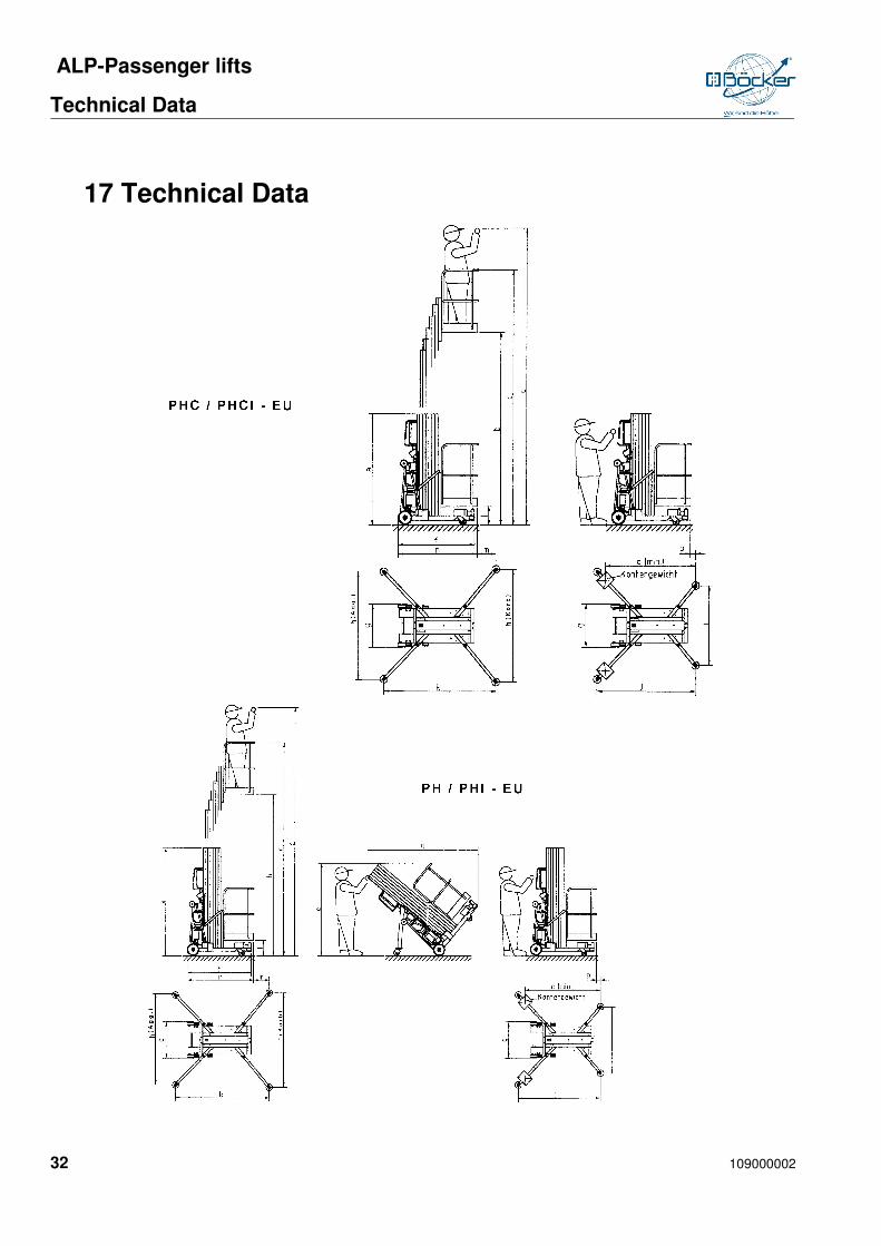
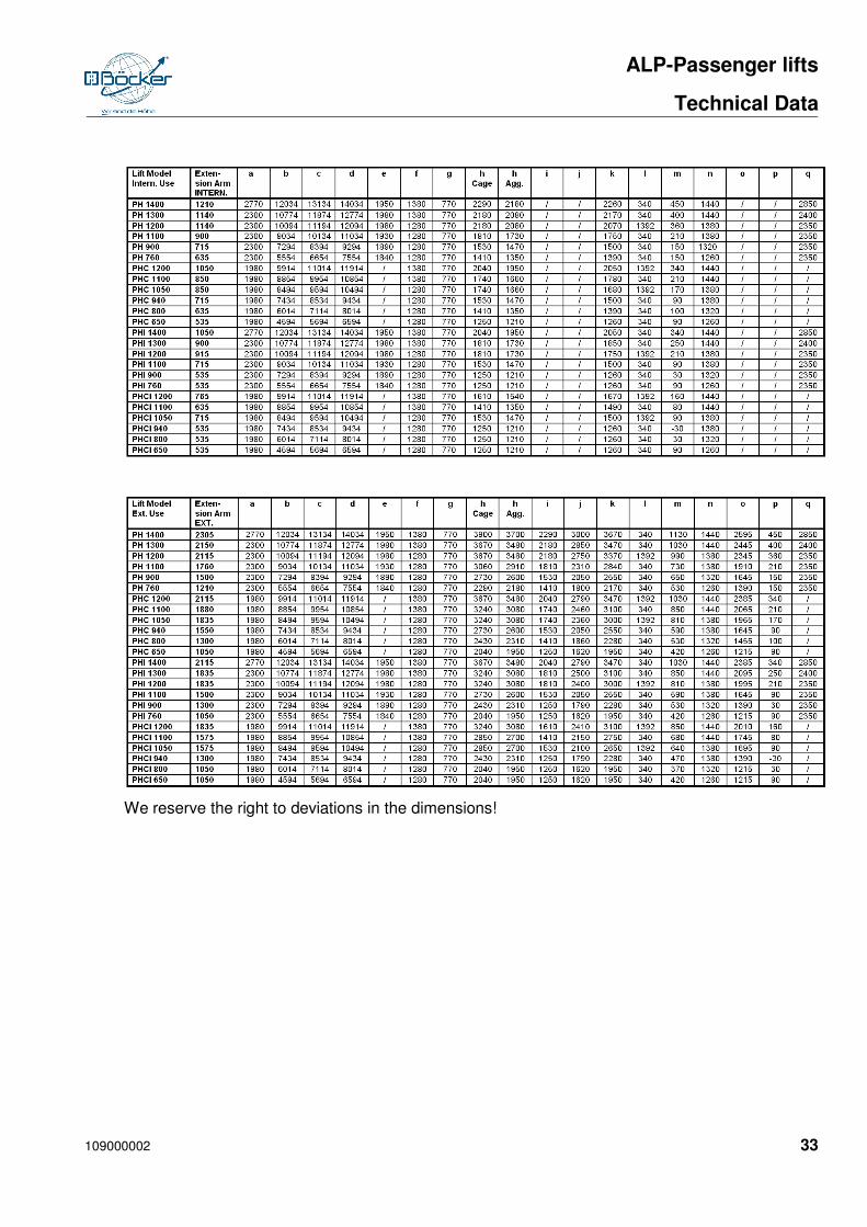
17 Technical Data
ALP-Passenger lifts
Technical Data
109000002 33
We reserve the right to deviations in the dimensions!
ALP-Passenger lifts
Special equipment and accessories
34 109000002
18 Special equipment and accessories
18.1 Additional operation from below
For this it must be ensured that the switching can only be conducted under control of the Operator. Additionally, the key for the switch must be removed prior to operation after the desired operating position has been selected.
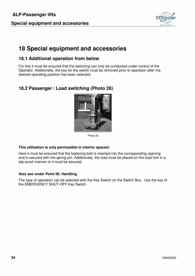
18.2 Passenger / Load switching (Photo 26)
Photo 26
This utilization is only permissible in interior spaces!
Here it must be ensured that the fastening bolt is inserted into the corresponding opening and is secured with the spring pin. Additionally, the load must be placed on the load fork in a slip-proof manner or it must be secured.
Also see under Point 06. Handling
The type of operation can be selected with the Key Switch on the Switch Box. Use the key of the EMERGENCY SHUT-OFF Key Switch.

ALP-Passenger lifts
Safety regulations
109000002 35
19 Safety regulations
In operation of the ALP Passenger Lifts, Accident Prevention Regulations are to be observed (UVV BGG 945-1Lift Working Platforms). The Safety Regulations of EN280 also apply. You can find an excerpt from these regulations in the Appendix.
ALP-Passenger lifts
Index
36 109000002
20 Index
A
Accessories .......................................... 34
Additional lowering ................................ 22
B
Battery .................................................. 25
BGG 945 ............................................... 29
D
Description .............................................. 7
E
electrical facilities .................................. 23
Emergency lowering ............................. 21
Event of disruption ................................ 30
Extension arm use ................................ 13
F
Foot operation ....................................... 18
H
Halfen anchoring systems ..................... 13
Handling ............................................... 15
I
Inspection ............................................. 28
Introduction ............................................. 6
L
Lift models ............................................ 24
M
Maintenance .......................................... 28
O
Operating the lift .................................... 17
Operation from below ............................ 34
P
Passenger / Load switching ................... 34
R
Regulations requiring compliance .......... 26
Replacement Parts ................................ 31
S
Safety facilities ...................................... 26
Safety regulastions ................................ 35
Special equipment ................................. 34
Stabile set up......................................... 10
Start up .................................................. 14
Switch box ............................................. 19
T
Technical data ....................................... 32
Transport ................................................. 8
Two-handed operation ........................... 18
U
Unauthorized use .................................. 20