B2641B1D-0837-4180-A478-65452526A32C31200241_ZF_Powershift Trans_4 WG-92-98 TSC

CSLSCompact Smart Laser Sensor
15 Columbia Drive • Amherst, NH 03031 USAPhone: (603) 883-3390 • Fax: (603) 886-3300
E-mail: [email protected]: www.monarchinstrument.com
Instruction Manual
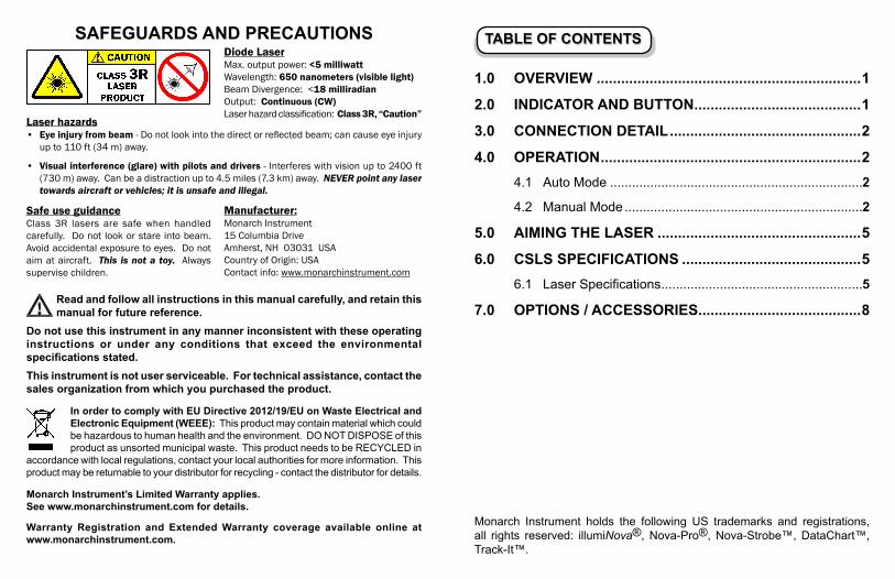
TABLE OF CONTENTSTABLE OF CONTENTS
1.0 OVERVIEW .................................................................1
2.0 INDICATOR AND BUTTON .........................................1
3.0 CONNECTION DETAIL ...............................................2
4.0 OPERATION ................................................................2
4.1 Auto Mode .....................................................................2
4.2 Manual Mode .................................................................2
5.0 AIMING THE LASER ..................................................5
6.0 CSLS SPECIFICATIONS ............................................5
6.1 Laser Specifi cations .......................................................5
7.0 OPTIONS / ACCESSORIES ........................................8
SAFEGUARDS AND PRECAUTIONS
Laser hazards• Eye injury from beam - Do not look into the direct or refl ected beam; can cause eye injury
up to 110 ft (34 m) away.
• Visual interference (glare) with pilots and drivers - Interferes with vision up to 2400 ft
(730 m) away. Can be a distraction up to 4.5 miles (7.3 km) away. NEVER point any laser
towards aircraft or vehicles; it is unsafe and illegal.
Safe use guidanceClass 3R lasers are safe when handled
carefully. Do not look or stare into beam.
Avoid accidental exposure to eyes. Do not
aim at aircraft. This is not a toy. Always
supervise children.
Read and follow all instructions in this manual carefully, and retain this
manual for future reference.
Do not use this instrument in any manner inconsistent with these operating
instructions or under any conditions that exceed the environmental
specifi cations stated.
This instrument is not user serviceable. For technical assistance, contact the
sales organization from which you purchased the product.
In order to comply with EU Directive 2012/19/EU on Waste Electrical and
Electronic Equipment (WEEE): This product may contain material which could
be hazardous to human health and the environment. DO NOT DISPOSE of this
product as unsorted municipal waste. This product needs to be RECYCLED in
accordance with local regulations, contact your local authorities for more information. This
product may be returnable to your distributor for recycling - contact the distributor for details.
Monarch Instrument’s Limited Warranty applies.
See www.monarchinstrument.com for details.
Warranty Registration and Extended Warranty coverage available online at
www.monarchinstrument.com.
Diode LaserMax. output power: <5 milliwatt
Wavelength: 650 nanometers (visible light)
Beam Divergence: <18 milliradian
Output: Continuous (CW)
Laser hazard classifi cation: Class 3R, “Caution”
Manufacturer:Monarch Instrument
15 Columbia Drive
Amherst, NH 03031 USA
Country of Origin: USA
Contact info: www.monarchinstrument.com
Monarch Instrument holds the following US trademarks and registrations,
all rights reserved: illumiNova®, Nova-Pro®, Nova-Strobe™, DataChart™,
Track-It™.

2
3.0 CONNECTION DETAIL
The unit has an four-pin M12 circular male connector for power and output
signals. A watertight mating connector with 9-foot [3m] molded cable is
supplied.
The connector on the unit has the following
connections:
4.0 OPERATION
The CSLS sensor emits a laser beam, which is refl ected back by the target
(refl ective tape/paint, keyway, contrasting colors, etc). This refl ected light
is sensed and amplifi ed. The gain of the input amplifi er can be adjusted
automatically or manually. The amplifi ed signal is compared against a
threshold for the digital output or is simply buffered for the analog output.
This allows the unit to be used with many types of targets at various distances
and contrasting color conditions.
The unit has two modes: Auto Mode and Manual Mode.
4.1 Auto Mode
In the Auto Mode the CSLS goes through a learning process to set the
gain to receive an optimum signal (LASER refl ections). It tries to set
the threshold up to certain level of the signal so that a periodic digital
output can be extracted. If the target signal is not periodic or it cannot be
analyzed by the CSLS, the unit will set the gain and threshold to some
1
1.0 OVERVIEW
The Compact Smart Laser Sensor (CSLS) is a self-contained optical
sensor intended to be used to make non-contact speed measurements from
rotating targets at distances up to 65 feet (19.8 m). The sensor has both digital
pulse and analog outputs to provide non-contact reference points to balancing
equipment or signals to a vibration analyzer. The sensor will track surface
irregularities on rotating shafts and provide pulse outputs from refl ective
tape, contrasting colors and keyways. Refer to section 4.0 for an overview
of operation. The sensor is IP64 rated and is suitable for use in dusty damp
environments. The unit has a removable plate with 1/4-20 bushing for tripod
mounting.
2.0 INDICATOR AND BUTTON
Status LED A single bicolor red/green LED indicates sensor status
(see operating modes for specifi cs)
Push button Short button press (less than 3 seconds) – In Auto
Mode will “learn” current conditions, In manual mode
will change the gain settings. (see operating modes for
specifi cs).
Long button press (greater than 3 seconds) – toggles
between Auto and Manual Mode, LED color will
indicate which mode the unit has entered (Green=Auto,
Red=Manual)

4
4.2 Manual Mode
In the Manual Mode the CSLS allows the user to set the gain manually.
When the device enters the Manual Mode for the fi rst time, it sets the
gain to the maximum available value (8). The user can then decrease
the gain value for optimal use.
To change the gain, fi rst aim the laser at your target. Press and release
the Learn/Mode button (less than 3 seconds) to change the gain of the
input amplifi er. Each time the button is pressed (for less than 3 seconds),
the gain is changed. The Status LED will blink at a fi xed rate to show
what gain has been selected. The number of LED blinks (after button
is pressed) identifi es the current gain index (8 down to 1). Once the gain
is at the lowest setting (gain index 1) it rolls over to highest level (gain
index 8) the next time the button is pressed. The weaker the signal, the
larger the gain index required. Using a large gain for a strong signal is
not recommended since the input will saturate.
Manual Mode LED Status Indication:
• Red = indicates unit has entered Manual Mode
• Steady/fi xed blinking Green LED = unit will blink green
indicating the gain index (8 through 1)
• Red LED blinking red = Warning before laser turns on
• Green LED blinking green = unit will blink green at the
input frequency when the unit is properly aimed. The LED
will appear on continuously at higher input frequencies.
The user can change to the Auto Mode by holding the Learn/Mode
button down for more than 3 seconds. Once the Status LED turns Green,
release the Learn/Mode button and the unit is now in the Auto Mode.
3
mid range value, which can detect high-level pulses (e.g. refl ective tape).
If there is no moving target (no signal), the CSLS will come out of the
learn process and set the gain and threshold to the same midrange values.
When the CSLS is fi rst powered on the unit enters the Auto/Learn Mode.
The Red LED will blink red several times to warn the user that the
Laser is going to turn on. Once the Laser is on, the unit starts the learn
process. The Green LED will blink green several times to indicate the
device is trying to get an optimal signal. Once the signal is detected,
the Green LED will turn off. The Green LED will then blink each time
a valid input signal is detected to indicate that the Laser is on target.
The Green LED will turn off if the Laser is not on target (or green LED
blinks at input frequency rate).
Auto/Learn Mode LED Status Indication:
• Red LED blinking red = Warning before laser turns on
• Green LED blinking green = initially unit is trying to get
optimal signal (learn process), then unit will blink green at the
input frequency when the unit is properly aimed. The LED
will appear on continuously at high speeds
• Green LED off = Laser is not on target
While in the Auto Mode, the user can press the Learn/Mode button (a
quick press less than 3 seconds) to have the unit “learn” a new target.
The user can also change to the Manual Mode by holding the Learn/
Mode button down for more than 3 seconds. Once the Status LED
turns Red, release the Learn/Mode button and the unit is now in the
Manual Mode.

6
Operating Range: Up to 65 feet depending on target refl ectivity:
1/2” refl ective tape (T-5) @3600 RPM: up to 65 ft. (19.8 m) or up to
75° from target
White/Black contrast @3600 RPM: up to 3 ft. (91 cm) or up to 45°
from target
Black mark on dental drill: up to 4 in. (10 cm) at over
260,000 RPM
Max RPM: 500,000 RPM
Min. Trigger Duration: 10 µsec
Indicators: Bicolor status LED for various operating functions - see above.
Modes: Auto/Normal (auto learn, automatic gain control) and Manual
(manual adjustment of sensitivity / gain)
Sensitivity Adjust: Push button (manual mode). Auto level adjust in
normal mode after “learn”.
Power Requirements: 5V +5% at 30mA max.
Pulse Output: With respect to the Common (Pin4)
Pin 3 Digital Output - 0 to 3.0V typical @ 5mA
positive going pulse (TTL Compatible)
Pin 2 Analog Output - analog signal tracks the
movement of the refl ecting source (emulates
an accelerometer signal)
Connector: M12 Circular 4-Pin Watertight Socket - Common, Power
(+5V), Analog Out, Digital Out
Mounting: Removable plate with ¼-20 UNC Bushing included (Tripod
Mount)
Weight: 4.8 oz (136.1 grams)
5
5.0 AIMING THE LASER
The proper operation of the Laser Sensor is dependent upon the alignment
to and refl ectivity of the target. In order to aim the beam it is necessary to
stand behind the sensor and view the target along the plane of the beam. Do
not stare directly into the laser beam or the refl ected light. For targets
greater than 5 feet and up to 65 feet from the sensor, mount the laser on a
tripod using the ¼ - 20 bushing on the bottom of the unit and attach T-5
refl ective tape to the target.
To aid in locating the laser dot over a large distance, hold a piece of white
cardboard or equivalent in front of the laser. Progressively move the white
surface closer to the desired target. Then adjust the aim of the laser as
necessary.
In areas of high ambient light (outdoors) or moist locations, performance
can be enhanced at long distances by slipping a piece of black tube with
a minimum inner diameter of 0.6 inches, over the nose piece to act as an
extension nose piece. This tube should not defl ect the beam in any way.
6.0 CSLS SPECIFICATIONS
Note: Product specifi cations are subject to change without notice.
6.1 Laser Specifi cations
Classifi cation: Class 3R (per IEC 60825-1 Edition 3 2014)
Complies with 21CFR 1040.10 and 1040.11 except
for deviations pursuant to Laser Notice No. 50, date
June 24, 2007.
Maximum Laser Output: <5mW
Pulse Duration: Continuous
Laser Wavelength: 650 nm
Beam Divergence: <18 mrad
Beam Diameter: 4 x 7 mm typical at 2 meters
Laser Diode Life: 8,000 hours MTBF (1 year warranty)

Dimensions: Approximately 3.5” (8.9 cm) (including 4-pin connector and
laser snout) x 2.4” (6.0 cm) x 2.2” (5.5 cm) (including button
and mounting pem) LxWxH
Compliance:
EMC: Directive 2014/30/EU - EN 61326-1:2013
Low Voltage: Directive 2014/35/EU
Electrical Safety: EN 61010-1:2010
Laser Safety: EN 60825-1:2014-3
Installation Environment:
Installation Category II per IEC 664
Pollution Degree Level III per IEC 61010-1
Temperature: 32 to 120 °F (0 to +50 °C) operating
14 to 158 °F (-10 to +70 °C) storage
Humidity: Maximum relative humidity of 80% for temperatures
up to 88 °F (31 °C) decreasing linearly to 50% relative
humidity at 104 °F (40 °C)
Specifi cations subject to change without notice.
87
7.0 OPTIONS / ACCESSORIES
T-5 Tape Refl ective Tape, 5 foot [1.5 m] roll, ½ inch [13 mm] wide
Additional lengths available 6180-070
T-5WP Tape Waterproof Refl ective Tape (honeycomb pattern), 5 foot [1.5 m] roll, 1 inch [25 mm] wide6180-079
CSLS-CA-P Power/Output Cable 9 foot [3 m] with molded M12 4-pin plug and 1/8” phone plug6180-039
CSLS-CA-W Replacement Power/Output Cable 9 foot [3 m] with molded M12 4-pin plug and 4 tinned leads (one supplied with unit)
Tripod Mini Miniature tripod for use with Monarch tachometers and stroboscopes
6180-040
1.57in
40mm
65.50mm
2.58in
89.18mm
3.51in
2.16in
54.96mm
2.38in
60.50mm
T-5 Tape
P/N: 6180-070
T-5WP Tape
P/N: 6180-079
CSLS-CA-P
P/N: 6180-039
CSLS-CA-W Tripod Mini
P/N: 6180-040

Check out some of our other product lines…
Handheld Panel Portable Machine Vision Tachometers Tachometers Stroboscopes Stroboscopes
Speed Sensors Temperature/ Vibration Meters
Humidity Sensors
Paperless Recorders Track-It™ Data Loggers
Printed in the U.S.A.
© Copyright 2011-2020 Monarch Instrument, all rights reserved.
1071- 4180-512- 0820