10.5 to 21.0 kW (3 to 6 Tons) - Allied Commercial · 10.5 to 21.0 kW (3 to 6 Tons) Net Cooling...
48
ZH Z-Series Rooftop Units 50 HZ Bulletin No. ZHA-036-060-50HZ (05/2017) 10.5 to 21.0 kW (3 to 6 Tons) Net Cooling Capacity − 9.1 to 17.3 kW (31 200 to 59 000 Btuh) Net Heating Capacity − 8.5 to 17.3 kW (29 000 to 59 000 Btuh) Optional Electric Heat - 3.8 to 23.0 kW MODEL NUMBER IDENTIFICATION Z H B 072 S 4 B N 1 m Brand/Family Z = Z-Series Unit Type H = Packaged Heat Pump Major Design Sequence A = 1st Generation B = 2nd Generation Nominal Cooling Capacity - Tons 036 = 10.5 kW (3 Tons) 048 = 14.0 kW (4 Tons) 060 = 17.5 kW (5 Tons) 072 = 21.0 kW (6 Tons) Cooling Efficiency S = Standard Efficiency Refrigerant Type 4 = R-410A Blower Type B = Belt Drive Factory Installed Electric Heat N = No Heat Minor Design Sequence 1 = 1st Revision 2 = 2nd Revision 3 = 3rd Revision Voltage M = 380/420V-3 phase-50hz PRODUCT SPECIFICATIONS PACKAGED ELECTRIC/electric
Transcript of 10.5 to 21.0 kW (3 to 6 Tons) - Allied Commercial · 10.5 to 21.0 kW (3 to 6 Tons) Net Cooling...

ZHZ-Series Rooftop Units
50 HZBulletin No. ZHA-036-060-50HZ (05/2017)
10.5 to 21.0 kW (3 to 6 Tons)Net Cooling Capacity − 9.1 to 17.3 kW (31 200 to 59 000 Btuh)Net Heating Capacity − 8.5 to 17.3 kW (29 000 to 59 000 Btuh)
Optional Electric Heat - 3.8 to 23.0 kW
MODEL NUMBER IDENTIFICATION
Z H B 072 S 4 B N 1 m
Brand/Family Z = Z-Series
Unit Type H = Packaged Heat Pump
Major Design Sequence A = 1st Generation
B = 2nd Generation
Nominal Cooling Capacity - Tons 036 = 10.5 kW (3 Tons) 048 = 14.0 kW (4 Tons) 060 = 17.5 kW (5 Tons) 072 = 21.0 kW (6 Tons)
Cooling Efficiency S = Standard Efficiency
Refrigerant Type 4 = R-410A
Blower Type B = Belt Drive
Factory Installed Electric Heat N = No Heat
Minor Design Sequence 1 = 1st Revision 2 = 2nd Revision 3 = 3rd Revision
Voltage M = 380/420V-3 phase-50hz
P R O D U C T S P E C I F I C AT I O N S
ZH 10.5 TO 21 KW ROOFTOP UNITS
PA C KA G E D E L E C T R I C / e l e c t r i c

Z-Series Packaged Heat Pump 10.5 to 21 kW - 50 hz / Page 2
FEATURES AND BENEFITS
Z-Series™rooftop units from Allied are the new standard for cost efficient, reliable rooftop units built for long-lasting performance that can significantly improve indoor environments. Z-Series™ rooftop units feature:• Quick and Easy Retrofit - Fast installation for replacement of many existing rooftop units - fits
high volume competitor’s roof curbs.• R-410A Refrigerant - Environmentally friendly.• Scroll Compressors - Single speed scroll compressor is furnished on all models.• High Pressure Switch - Protects compressor.• Belt Drive Blower Motor - To maximize air performance.• Downflow or Horizontal Airflow - Easy field conversion.• Two Fork Lift Slots on Three Sides - Easy to pick up and transport units from almost any
angle.• Corrosion-Resistant Drain Pan - Provides application flexibility, durability, and improved
serviceability.• Thermostatic Expansion Valve - Provides peak heating performance across the entire
application range.• Common Components - Many maintenance items are standard throughout the entire product
line, reducing the need to carry different parts to the job or maintain in inventory.
B
D
E
F
G
H
I
C
(ZHA060 Model Shown)

Z-Series Packaged Heat Pump 10.5 to 21 kW - 50 hz / Page 3
FEATURES AND BENEFITS
TESTINGComponents bonded for grounding to meet safety standards for servicing required by Underwriters Laboratories (UL) and the International Electrotechnical Commission (IEC).Cooling performance is rated at test conditions included in Air-Conditioning, Heating and Refrigeration Institute (AHRI) Standards 210/24-02008 (10.5 - 17.5 kW) and 340/360-2007 (21 kW models) while operating at rated voltage and air volumes. International Organization for Standardization (ISO) 9001 Registered Manufacturing Quality System.
COOLING / HEATING SYSTEMDesigned to maximize sensible and latent cooling performance at design conditions.System can operate from -18°C to 52°C without any additional controls.
R-410A RefrigerantNon-chlorine, ozone friendly, R-410A.Unit is factory pre-charged with refrigerant. See Specifications Table.
CompressorResiliently mounted on rubber grommets for quiet operation.Scroll compressors for high performance, reliability and quiet operation.
Compressor Crankcase HeaterProtects against refrigerant migration that can occur during low ambient operation.
Refrigerant Metering Orifice (All ZHA and ZHB036 to 060 models) Accurately meters refrigerant in system. Refrigerant control is accomplished by exact sizing of refrigerant metering orifice.
B
Thermal Expansion Valve (ZHB072 models)Assures optimal performance throughout the application range. Removable element head.
High Pressure SwitchProtects the compressor from overload conditions such as dirty condenser coils, blocked refrigerant flow, or loss of outdoor fan operation.Automatic reset.
Reversing Valve4-way interchange reversing valve effects a rapid change in direction of refrigerant flow resulting in quick changeover from cooling to heating and vice versa.
Defrost ControlProvides a defrost cycle, if needed, every 30 or 60 or 90 minutes (adjustable) of compressor “on” time at outdoor coil temperature below 2°C. Temperature switch mounted on outdoor coil liquid line terminates defrost cycle.
Filter/DrierHigh capacity filter/drier protects the system from dirt and moisture.
Coil ConstructionCopper tube construction, enhanced rippled-edge aluminum fins, flared shoulder tubing connections, silver soldered construction for improved heat transfer. Factory leak tested.
Indoor CoilCross row circuiting with rifled tubing optimizes both sensible and latent cooling capacity.
Condensate Drain PanPlastic pan, sloped to meet drainage requirements of the American Society of Heating Refrigeration and Air Conditioning Engineers (ASHRAE) 62.1.End drain connection.
Outdoor Coil Fan MotorThermal overload protected, totally enclosed, permanently lubricated bearings, shaft down (all ZHA and ZHB036 to 060 models), shaft up (ZHB072) fan guard mount.
C
D
CONTENTSBlower Data . . . . . . . . . . . . . . . . . . . . . . . . . . . . . . . . .19Cooling / Heating Ratings. . . . . . . . . . . . . . . . . . . . . . . . . .12Dimensions - Accessories. . . . . . . . . . . . . . . . . . . . . . . . . .43Dimensions - Unit - ZHA . . . . . . . . . . . . . . . . . . . . . . . . . .41Dimensions - Unit - ZHB . . . . . . . . . . . . . . . . . . . . . . . . . .42Electrical/Electric Heat Data - ZHA . . . . . . . . . . . . . . . . . . . . .35Electrical/Electric Heat Data - ZHB . . . . . . . . . . . . . . . . . . . . .36Features And Benefits . . . . . . . . . . . . . . . . . . . . . . . . . . . 2Model Number Identification . . . . . . . . . . . . . . . . . . . . . . . . 1Options / Accessories . . . . . . . . . . . . . . . . . . . . . . . . . . . . 8Specifications - ZHA . . . . . . . . . . . . . . . . . . . . . . . . . . . .10Specifications - ZHB . . . . . . . . . . . . . . . . . . . . . . . . . . . .11Unit Clearances . . . . . . . . . . . . . . . . . . . . . . . . . . . . . . .38Weight Data . . . . . . . . . . . . . . . . . . . . . . . . . . . . . . . . .40

Z-Series Packaged Heat Pump 10.5 to 21 kW - 50 hz / Page 4
COOLING / HEATING SYSTEM (continued)
Outdoor Coil Fan GuardPolyvinyl chloride (PVC) coated fan guard furnished.
Required Selections
Cooling CapacitySpecify nominal cooling capacity of the unit.
Options/Accessories
Field InstalledCondensate Drain TrapField installed only.Available in copper or polyvinyl chloride (PVC).
Drain Pan Overflow SwitchMonitors condensate level in drain pan, shuts down unit if drain becomes clogged.
Low Ambient KitCycles the outdoor fan while allowing compressor operation in the cooling cycle. This intermittent fan operation allows the system to operate without icing the evaporator coil and losing capacity. Designed for use in ambient temperatures no lower than -18°C.
CABINETConstructionHeavy-gauge steel panels and full perimeter heavy-gauge galvanized steel base rail provides structural integrity for transportation, handling, and installation.Base rails have rigging holes. Three sides of the base rail have fork slots.Raised edges around duct and power entry openings in the bottom of the unit provide additional protection against water entering the building.
Airflow ChoiceUnits are shipped in downflow (vertical) configuration, can be field converted to horizontal airflow configuration without the need of a kit.
Power EntryElectrical lines can be brought through the unit base or through horizontal access knock-outs (end of unit on 036-060 model, side of unit on ZHB072 models).ZHB072 models feature three mounting locations for the disconnect:• Side mounting on an
adjustable panel (removable corner base rail allows access for installation)
• Side mounting directly over the side power entry knockouts
• End mounting on an adjustable panel (alternate location)
See dimension drawing.Optional Bottom Power Entry Kit is available.
Exterior PanelsConstructed of heavy-gauge, galvanized steel with a two-layer enamel paint finish.
InsulationAll panels adjacent to conditioned air are fully insulated with non-hygroscopic fiberglass insulation.
E
F
G
H
Access PanelsAccess panels are provided for the compressor, heating, controls, blower and air filter/economizer section.
Options/Accessories
Factory InstalledCorrosion ProtectionA completely flexible immersed coating with an electro-deposited dry film process. (AST ElectroFin E-Coat) Meets Mil Spec MIL-P-53084, ASTM B117 Standard Method Salt Spray Testing.Indoor Corrosion Protection: - Coated coilOutdoor Corrosion Protection: - Coated coil
Field InstalledCombination Coil/Hail GuardsHeavy gauge steel frame painted to match cabinet with expanded metal mesh to protect the outdoor coil from damage.
FEATURES AND BENEFITS

Z-Series Packaged Heat Pump 10.5 to 21 kW - 50 hz / Page 5
CONTROLSUnit ControlAll control voltage is provided via a 24V (secondary) transformer with inline fuse protection.
Heat/Cool StagingCapable of up to 2 heat / 2 cool staging with a thermostat.Night Setback ModeSaves energy by closing outdoor air dampers and operating supply fan on thermostat demand only.
Smoke DetectorsNOTE - Smoke detectors are not available and must be field provided by installer.
BLOWERA wide selection of supply air blower options are available to meet a variety of air flow requirements.
MotorOverload protected, equipped with ball bearings. Belt drive motors are offered on all models and are available in several different sizes to maximize air performance.
Supply Air BlowerForward curved blades, blower wheel is statically and dynamically balanced.Equipped with ball bearings and adjustable pulley (allows speed change).
Required Selections
Supply Air BlowerOrder blower motor kW and drive kit number required when base unit is ordered, see Drive Kit Specifications Table.
I INDOOR AIR QUALITYAir FiltersDisposable 51 mm filters furnished as standard.
Options/Accessories
Field InstalledIndoor Air Quality (CO2) SensorMonitors CO2 levels adjusts economizer dampers as needed for Demand Control Ventilation.
ELECTRICALMarked & Color-Coded WiringAll electrical wiring is color-coded and marked to identify which components it is connecting.
Electrical PlugsPositive connection electrical plugs are used to connect common accessories or maintenance parts for easy removal or installation.
Required SelectionsVoltage ChoiceSpecify when ordering base unit.
Field InstalledBottom Power Entry KitKit reduces the number of penetrations in the roof.Kit includes bulkhead connectors to provides power and control wiring routing through the roof curb.
Electric HeatHelix wound nichrome elements, individual element limit controls, wiring harness. See Options / Accessories tables for ordering information.NOTE - Unit Fuse Block is required and must be ordered separately. See Electrical/Electric Heat tables for ordering information.
FEATURES AND BENEFITS
Z-Series Packaged Heat Pump 10.5 to 21 kW - 50 hz / Page 6
ECONOMIZER OPTIONS
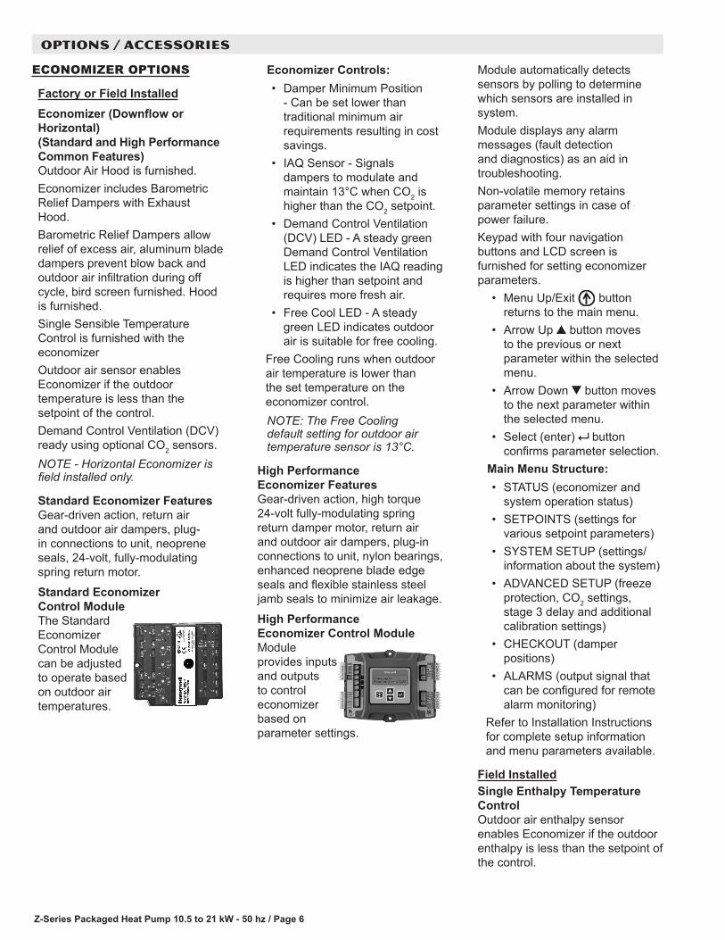
Factory or Field InstalledEconomizer (Downflow or Horizontal) (Standard and High Performance Common Features)Outdoor Air Hood is furnished.Economizer includes Barometric Relief Dampers with Exhaust Hood.Barometric Relief Dampers allow relief of excess air, aluminum blade dampers prevent blow back and outdoor air infiltration during off cycle, bird screen furnished. Hood is furnished.Single Sensible Temperature Control is furnished with the economizerOutdoor air sensor enables Economizer if the outdoor temperature is less than the setpoint of the control.Demand Control Ventilation (DCV) ready using optional CO2 sensors.NOTE - Horizontal Economizer is field installed only.
Standard Economizer Features Gear-driven action, return air and outdoor air dampers, plug-in connections to unit, neoprene seals, 24-volt, fully-modulating spring return motor.
Standard Economizer Control ModuleThe Standard Economizer Control Module can be adjusted to operate based on outdoor air temperatures.
Economizer Controls:• Damper Minimum Position
- Can be set lower than traditional minimum air requirements resulting in cost savings.
• IAQ Sensor - Signals dampers to modulate and maintain 13°C when CO2 is higher than the CO2 setpoint.
• Demand Control Ventilation (DCV) LED - A steady green Demand Control Ventilation LED indicates the IAQ reading is higher than setpoint and requires more fresh air.
• Free Cool LED - A steady green LED indicates outdoor air is suitable for free cooling.
Free Cooling runs when outdoor air temperature is lower than the set temperature on the economizer control. NOTE: The Free Cooling default setting for outdoor air temperature sensor is 13°C.
High Performance Economizer Features Gear-driven action, high torque 24-volt fully-modulating spring return damper motor, return air and outdoor air dampers, plug-in connections to unit, nylon bearings, enhanced neoprene blade edge seals and flexible stainless steel jamb seals to minimize air leakage.
High Performance Economizer Control Module Module provides inputs and outputs to control economizer based on parameter settings.
OPTIONS / ACCESSORIES
Module automatically detects sensors by polling to determine which sensors are installed in system.Module displays any alarm messages (fault detection and diagnostics) as an aid in troubleshooting.Non-volatile memory retains parameter settings in case of power failure.Keypad with four navigation buttons and LCD screen is furnished for setting economizer parameters.
• Menu Up/Exit button returns to the main menu.
• Arrow Up button moves to the previous or next parameter within the selected menu.
• Arrow Down button moves to the next parameter within the selected menu.
• Select (enter) button confirms parameter selection.
Main Menu Structure:• STATUS (economizer and
system operation status)• SETPOINTS (settings for
various setpoint parameters)• SYSTEM SETUP (settings/
information about the system)• ADVANCED SETUP (freeze
protection, CO2 settings, stage 3 delay and additional calibration settings)
• CHECKOUT (damper positions)
• ALARMS (output signal that can be configured for remote alarm monitoring)
Refer to Installation Instructions for complete setup information and menu parameters available.
Field InstalledSingle Enthalpy Temperature Control Outdoor air enthalpy sensor enables Economizer if the outdoor enthalpy is less than the setpoint of the control.
Z-Series Packaged Heat Pump 10.5 to 21 kW - 50 hz / Page 7
OPTIONS / ACCESSORIES
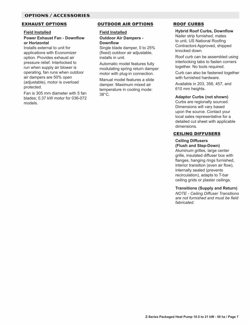
EXHAUST OPTIONS
Field InstalledPower Exhaust Fan - Downflow or HorizontalInstalls external to unit for applications with Economizer option. Provides exhaust air pressure relief. Interlocked to run when supply air blower is operating, fan runs when outdoor air dampers are 50% open (adjustable), motor is overload protected.Fan is 305 mm diameter with 5 fan blades; 0.37 kW motor for 036-072 models.
OUTDOOR AIR OPTIONS
Field InstalledOutdoor Air Dampers - DownflowSingle blade damper, 0 to 25% (fixed) outdoor air adjustable, installs in unit.Automatic model features fully modulating spring return damper motor with plug-in connection.Manual model features a slide damper. Maximum mixed air temperature in cooling mode: 38°C.
ROOF CURBSHybrid Roof Curbs, DownflowNailer strip furnished, mates to unit, US National Roofing Contractors Approved, shipped knocked down.Roof curb can be assembled using interlocking tabs to fasten corners together. No tools required.Curb can also be fastened together with furnished hardware.Available in 203, 356, 457, and 610 mm heights.
Adaptor Curbs (not shown)Curbs are regionally sourced. Dimensions will vary based upon the source. Contact your local sales representative for a detailed cut sheet with applicable dimensions.
CEILING DIFFUSERSCeiling Diffusers (Flush and Step-Down)Aluminum grilles, large center grille, insulated diffuser box with flanges, hanging rings furnished, interior transition (even air flow), internally sealed (prevents recirculation), adapts to T-bar ceiling grids or plaster ceilings.
Transitions (Supply and Return)NOTE - Ceiling Diffuser Transitions are not furnished and must be field fabricated.

Z-Series Packaged Heat Pump 10.5 to 21 kW - 50 hz / Page 8
OPTIONS / ACCESSORIESItem Catalog
No.ZHA ZHB 036
ZHA ZHB 048
ZHA ZHB 060
ZHB 072
COOLING SYSTEM
Condensate Drain Trap Polyvinyl Chloride (PVC) - C1TRAP20AD2 76W26 X X X XCopper - C1TRAP10AD2 76W27 X X X X
Drain Pan Overflow Switch Z1SNSR90A1 99W59 X X X XLow Ambient Kit Z1SNSR34A-1 99W68 X X X X
Blower - SUPPLY AIR
Motors Belt Drive - 0.62 kW Standard Efficiency Factory O OBelt Drive - 0.93 kW Standard Efficiency Factory O O O OBelt Drive - 1.24 kW Standard Efficiency Factory O O
Drive Kits See Blower Data Tables for selection
Kit #ZA07 - 705-1077 rev/min Factory OKit #ZA08 - 759-1158 rev/min Factory OKit #ZA09 - 919-1247 rev/min Factory O
Kit #ZA10 - 1025-1391 rev/min Factory O1 Kit #ZA11 - 1111-1437 rev/min Factory O
2 Kit #ZA12 - 1190-1540 rev/min Factory OKit #ZAA02 - 527-729 rev/min Factory OKit #ZAA03 - 665 -921 rev/min Factory O OKit #ZAA04 - 768-1023 rev/min Factory O OKit #ZAA05 - 921-1177 rev/min Factory O
CABINET
Combination Coil/Hail Guards ZHA models only - Z1GARD52A-1 12X19 X XZHA060 and ZHB models only - Z1GARD20AT1 12X20 X X X
ZHB072 model only - Z1GARD20AL1 16A41 XCorrosion Protection Factory O O O O
ELECTRICAL
Voltage 50 hz with neutral 380/420V - 3 phase Factory O O O OBottom Power Entry Kit Z1PEKT01A-1 98W08 X X X X3 ELECTRIC HEAT
3.8 kW 380/420V-3ph - Z1EH0050AN1G 99W06 X X X5.7 kW 380/420V-3ph - Z1EH0075AN1G 99W07 X X X X7.7 kW 380/420V-3ph - Z1EH0100AN1G 99W08 X X X X11.5 kW 380/420V-3ph - Z1EH0150AN1G 99W09 X X X X17.2 kW 380/420V-3ph - Z1EH0225AN1G 99W10 X X X23 kW 380/420V-3ph - Z1EH0300A-1G 13U02 X
ELECTRIC HEAT ACCESSORIES
Unit Fuse Block (required) - See Electrical/Electric Heat Tables for Selection X X X X1 ZA11 drive kits require the 0.93 kW motor.2 ZA12 drive kit requires the 1.24 kW motor.3 Nominal kW at 420V-3ph-50hz.
NOTE - The catalog and model numbers that appear here are for ordering field installed accessories only.OX - Field Installed or Configure to Order (factory installed)O - Configure to Order (factory installed)X - Field Installed.

Z-Series Packaged Heat Pump 10.5 to 21 kW - 50 hz / Page 9
OPTIONS / ACCESSORIESItem Catalog
No.ZHA ZHB 036
ZHA ZHB 048
ZHA ZHB 060
ZHB 072
ECONOMIZER
Standard Economizer With Outdoor Air HoodStandard Economizer (Downflow) Includes Barometric Relief Dampers and Exhaust Hood
Z1ECON30A-2 14D94 OX OX OX OX
Standard Economizer (Horizontal) Includes Barometric Relief Dampers and Exhaust Hood
Z1ECON16A-2 14D92 X X X X
Standard Economizer ControlsSingle Enthalpy Control C1SNSR64FF1 53W64 X X X XHigh Performance Economizer With Outdoor Air HoodHigh Performance Economizer (Downflow) Includes Barometric Relief Dampers and Exhaust Hood
Z1ECON32A-2 14D95 OX OX OX OX
High Performance Economizer (Horizontal) Includes Barometric Relief Dampers and Exhaust Hood
Z1ECON33A-2 14D93 X X X X
High Performance Economizer ControlsSingle Enthalpy Control C1SNSR61FF1 11G21 X X X X
OUTDOOR AIR
Outdoor Air Dampers - Includes Outdoor Air HoodMotorized Z1DAMP21A-2 15D19 X X X XManual Z1DAMP11A-2 15D20 X X X X
Power EXhaust FAN
Standard Static (Downflow) 380/420V-3ph - Z1PWRE10A-1G 23E01 X X X XStandard Static (Horizontal) 380/420V-3ph - Z1PWRE15A-1G 28E01 X X X X
Indoor Air Quality
Indoor Air Quality (CO2) SensorsSensor - Wall-mount, off-white plastic cover with LCD display C0SNSR50AE1L 77N39 X X X X
Sensor - Wall-mount, black plastic case, no display, rated for plenum mounting
C0SNSR53AE1L 87N54 X X X X
CO2 Sensor Duct Mounting Kit - for downflow applications C0MISC19AE1 85L43 X X X X
Aspiration Box - for duct mounting non-plenum rated CO2 sensor (77N39)
C0MISC16AE1 90N43 X X X X
ROOF CURBS
Hybrid Roof Curbs, Downflow203 mm height Z1CURB70A-1 11F76 X X X X356 mm height Z1CURB71A-1 11F77 X X X X457 mm height Z1CURB72A-1 11F78 X X X X610 mm height Z1CURB73A-1 11F79 X X X X
CEILING DIFFUSERS
Step-Down - Order one RTD9-65S 13K60 X X X
RTD11-95S 13K61 X
Flush - Order one FD9-65S 13K55 X X X
FD11-95S 13K56 XNOTE - Ceiling Diffuser Transitions are not furnished and must be field fabricated.
NOTE - The catalog and model numbers that appear here are for ordering field installed accessories only.OX - Field Installed or Configure to Order (factory installed)O - Configure to Order (factory installed)X - Field Installed.

Z-Series Packaged Heat Pump 10.5 to 21 kW - 50 hz / Page 10
SPECIFICATIONS - ZHAGeneral Data Nominal Size 10.5 kW (3 Ton) 14.0 kW (4 Ton) 17.5 kW (5 Ton)
Model No. ZHA036S4B ZHA048S4B ZHA060S4BEfficiency Type Standard Standard Standard
Cooling Performance
Gross Cooling Capacity - kW (Btuh) 9.6 (32 600) 12.2 (41 700) 15.4 (52 400)1 Net Cooling Capacity - kW (Btuh) 9.1 (31 200) 11.5 (39 500) 14.7 (50 000)
Rated Air Flow - L/s (cfm) 618 (1310) 760 (1610) 916 (1940)2 Sound Rating Number (SRN) (dBA) Cooling 79 79 83
Heating 80 80 83Total Unit Power - kW 2.6 3.7 4.5
1 SEER (Btuh/Watt) 13.00 13.00 13.001 EER (Btuh/Watt) 11.80 10.80 11.00
Refrigerant Type R-410A R-410A R-410ACharge Furnished 5.3 kg (11 lbs. 12 oz.) 5.7 kg (12 lbs. 8 oz.) 6.9 kg (15 lbs. 3 oz.)
Heating Performance
Total High Heating Capacity - (kW) Btuh 8.5 (29 000) 11.3 (38 500) 14.7 (50 000)Total Unit Power - kW 2.4 3.2 4.1
1 COP 3.52 3.56 3.62Total Low Heating Capacity - (kW) Btuh 5.0 (17 200) 6.9 (23 400) 8.4 (28 600)
Total Unit Power - kW 2.3 3.0 3.8COP 2.18 2.28 2.22
Electric Heat Available - See page 8 3.8, 5.7, 7.7, 11.5 kW 3.8, 5.7, 7.7, 11.5, 17.2 kWCompressor Type (one per unit) Scroll Scroll ScrollOutdoor Coil Net face area - m2 (sq. ft.) 4.9 (16.1) 4.9 (16.1) 6.1 (20.1)
Tube diameter - mm (in.) 9.5 (3/8) 9.5 (3/8) 9.5 (3/8)Number of rows 2 2 2
Fins / meter (inch) 787 (20) 787 (20) 787 (20)Expansion Device Type Balanced port TXV, removable head
Outdoor Coil Fan
Motor W (HP) (1) 190 (1/4) (1) 190 (1/4) (1) 250 (1/3)Motor rev/min 688 688 896
Total motor watts 229 229 260Diameter - mm (in.) (1) 559 (22) (1) 559 (22) (1) 559 (22)
Number of blades 4 4 3Total air volume - L/s (cfm) 1258 (2667) 1258 (2667) 1415 (3000)
Indoor Coil Net face area - m2 (sq. ft.) 0.78 (8.4) 0.78 (8.4) 0.89 (9.6)Tube diameter - mm (in.) 9.5 (3/8) 9.5 (3/8) 9.5 (3/8)
Number of rows 3 3 3Fins per meter (in.) 551 (14) 551 (14) 551 (14)
Drain Connection (no. and size) - in. (1) 1 NPT (1) 1 NPT (1) 1 NPTExpansion device type Fixed Orifice Fixed Orifice Fixed Orifice
3 Indoor Blower & Drive Selection
Nominal Motor kW (HP) 0.62 kW (0.83 hp), 0.93 kW (1.25 hp)
0.62 kW (0.83 hp), 0.93 kW (1.25 hp)
0.93 kW (1.25 hp), 1.24 kW (1.66 hp)
Maximum Usable Motor kW (HP) 0.71 kW (0.95 hp), 1.07 kW (1.43 hp)
0.71 kW (0.95 hp), 1.07 kW (1.43 hp)
1.07 kW (1.43 hp), 1.42 kW (1.91 hp)
Available Drive Kits Kit #ZA07 705-1077 rev/min
Kit #ZA10 1025-1391 rev/min
Kit #ZA08 759-1158 rev/min
4 Kit #ZA11 1111-1437 rev/min
Kit #ZA09 919-1247 rev/min
5 Kit #ZA12 1190-1540 rev/min
Wheel nominal diameter x width - mm (in.) 254 x 254 (10 x 10) 254 x 254 (10 x 10) 254 x 254 (10 x 10)Filters Type Disposable
Number and size - mm (in.) (4) 356 x 508 x 51 (14 x 20 x 2)
(4) 406 x 508 x 51 (16 x 20 x 2)
Electrical Characteristics - 50 Hz 380/420V - 50 hertz - 3 phase with neutralNOTE - Net capacity includes evaporator blower motor heat deduction. Gross capacity does not include evaporator blower motor heat deduction.1 Rating test conditions are those included in Air-Conditioning, Heating and Refrigeration Institute (AHRI) Standard 210/240 while operating at rated voltage and air
volumes; Cooling Ratings - 35°C (95°F) outdoor air temperature and 26°C (80°F) db/19°C (67°F) wb entering indoor coil air. High Temperature Heating Ratings - 8°C (47°F) db/6°C (43°F) wb outdoor air temperature and 21°C (70°F) entering indoor coil air. Low Temperature Heating Ratings - -8°C (17°F) db/-9°C (15°F) wb outdoor air temperature and 21°C (70°F) entering indoor coil air.
2 Sound Rating Number (SRN) rated in accordance with test conditions included in ANSI/AHRI Standard 270-2008.3 Using total air volume and system static pressure requirements determine from blower performance tables rev/min and motor size required. Maximum usable size of
motors furnished is shown. If motors of comparable size are used, be sure to keep within the service factor limitations outlined on the motor nameplate. 0.62 kW = 0.83 hp (1.0 nominal hp) while operating at rated voltage and frequency. 0.93 kW = 1.25 hp (1.5 nominal hp) while operating at rated voltage and frequency. 1.24 kW = 1.66 hp (2.0 nominal hp) while operating at rated voltage and frequency.
4 ZA11 drive kits require the 0.93 kW motor.5 ZA12 drive kit requires the 1.24 kW motor.

Z-Series Packaged Heat Pump 10.5 to 21 kW - 50 hz / Page 11
SPECIFICATIONS - ZHBGeneral Data Nominal Size 10.5 kW (3 Ton) 14.0 kW (4 Ton) 17.5 kW (5 Ton) 21 kW (6 Ton)
Model No. ZHB036S4B ZHB048S4B ZHB060S4B ZHB072S4BEfficiency Type Standard Standard Standard Standard
Cooling Performance
Gross Cooling Capacity - kW (Btuh) 9.1 (31 200) 12.2 (41 700) 15.4 (52 400) 17.9 (61 000)Net Cooling Capacity - kW (Btuh) 1 8.8 (29 900) 1 11.5 (39 500) 1 14.7 (50 000) 2 17.3 (59,000)
Rated Air Flow - L/s (cfm) 595 (1260) 760 (1610) 916 (1940) 877 (1860)3 Sound Rating Number (SRN) (dBA) Cooling 79 77 82 86
Total Unit Power - kW 2.6 3.5 4.3 5.4SEER 1 14.00 1 14.00 1 14.00 - - -
EER (Btuh/Watt) 1 11.50 1 11.40 1 11.30 2 11.10Refrigerant Type R-410A R-410A R-410A R-410A
Charge Furnished 6.6 kg (14 lbs. 8 oz.)
7.4 kg (16 lbs. 5 oz.)
6.5 kg (14 lbs. 4 oz.)
8.2 kg (18 lbs. 0 oz.)
Heating Performance
Total High Heating Capacity - (kW) Btuh 8.5 (29 100) 11.3 (38 500) 14.7 (50 000) 17.3 (59 000)Total Unit Power - kW 2.4 3.1 3.6 4.9
1 COP 3.6 3.6 3.7 3.4Total Low Heating Capacity - (kW) Btuh 5.2 (17 700) 8.2 (28 800) 10.1 (34 400) 9.7 (33 000)
Total Unit Power - kW 2.2 3.1 3.5 4.3COP 2.3 2.4 2.4 2.3
Electric Heat Available - See page 8 3.8, 5.7, 7.7, 11.5 kW 3.8, 5.7, 7.7, 11.5, 17.2 kW 5.7, 7.7, 11.5,
17.2, 23 kWCompressor Type (one per unit) Scroll Scroll Scroll ScrollOutdoor Coil Net face area - m2 (sq. ft.) 1.8 (19.9) 1.8 (19.9) 1.8 (19.9) 2.3 (25)
Tube diameter - mm (in.) 9.5 (3/8) 9.5 (3/8) 9.5 (3/8) 9.5 (3/8)Number of rows 2 2 2 2
Fins / meter (inch) 787 (20) 787 (20) 787 (20) 787 (20)Expansion Device Type Balanced port TXV, removable head
Outdoor Coil Fan
Motor W (HP) (1) 190 (1/4) (1) 190 (1/4) (1) 250 (1/3) (1) 250 (1/3)Motor rev/min 688 688 896 900
Total motor watts 229 229 260 266Diameter - mm (in.) (1) 559 (22) (1) 559 (22) (1) 559 (22) (1) 610 (24)
Number of blades 4 4 3 3Total air volume - L/s (cfm) 1574 (3335) 1574 (3335) 1699 (3600) 1770 (3750)
Indoor Coil Net face area - m2 (sq. ft.) 0.89 (9.6) 1.0 (10.8) 1.0 (10.8) 1.0 (10.8)Tube diameter - mm (in.) 9.5 (3/8) 9.5 (3/8) 9.5 (3/8) 9.5 (3/8)
Number of rows 3 3 3 3Fins per meter (in.) 551 (14) 551 (14) 551 (14) 551 (14)
Drain Connection (no. and size) - in. (1) 1 NPT (1) 1 NPT (1) 1 NPT (1) 1 NPTExpansion device type
Fixed Orifice Fixed Orifice Fixed OrificeBalanced Port
TXV, removable power head
4 Indoor Blower & Drive Selection
Nominal Motor kW (HP) 0.62 kW (0.83 hp), 0.93 kW (1.25 hp)
0.62 kW (0.83 hp), 0.93 kW (1.25 hp)
0.93 kW (1.25 hp), 1.24 kW (1.66 hp)
0.93 kW (1.25 hp), 1.24 kW (1.66 hp)
Maximum Usable Motor kW (HP) 0.71 kW (0.95 hp), 1.07 kW (1.43 hp)
0.71 kW (0.95 hp), 1.07 kW (1.43 hp)
1.07 kW (1.43 hp), 1.42 kW (1.91 hp)
1.07 kW (1.43 hp), 1.42 kW (1.91 hp)
Available Drive Kits Kit #ZA07 705-1077 rev/min
Kit #ZA10 1025-1391
rev/min
Kit #ZA08 759-1158 rev/min
5 Kit #ZA11 1111-1437
rev/min
Kit #ZAA02 527-729 rev/min
Kit #ZAA03 665-921 rev/min
Kit #ZAA04 768-1023 rev/min
Kit #ZAA03 665-921 rev/min
Kit #ZAA04 768-1023 rev/min
Kit #ZAA05 921-1177 rev/min
Wheel nominal diameter x width - mm (in.) 254 x 254 (10 x 10)
254 x 254 (10 x 10)
381 x 229 (15 x 9)
381 x 229 (15 x 9)
Filters Type DisposableNumber and size - mm (in.) (4) 406 x 508 x 51
(16 x 20 x 2)(2) 406 x 508 x 51 (16 x 20 x 2) (2) 508 x 508 x 51 (20 x 20 x 2)
Electrical Characteristics - 50 Hz 380/420V - 50 hertz - 3 phase with neutralNOTE - Net capacity includes evaporator blower motor heat deduction. Gross capacity does not include evaporator blower motor heat deduction.1, 2 Rating test conditions are those included in Air-Conditioning, Heating and Refrigeration Institute (AHRI) Standard 1 210/240 or 2 340/360 while operating at rated
voltage and air volumes; Cooling Ratings - 35°C (95°F) outdoor air temperature and 26°C (80°F) db/19°C (67°F) wb entering indoor coil air. High Temperature Heating Ratings - 8°C (47°F) db/6°C (43°F) wb outdoor air temperature and 21°C (70°F) entering indoor coil air. Low Temperature Heating Ratings - -8°C (17°F) db/-9°C (15°F) wb outdoor air temperature and 21°C (70°F) entering indoor coil air.
3 Sound Rating Number (SRN) rated in accordance with test conditions included in ANSI/AHRI Standard 270-2008.4 Using total air volume and system static pressure requirements determine from blower performance tables rev/min and motor size required. Maximum usable size of
motors furnished is shown. If motors of comparable size are used, be sure to keep within the service factor limitations outlined on the motor nameplate. 0.62 kW = 0.83 hp (1.0 nominal hp) while operating at rated voltage and frequency. 0.93 kW = 1.25 hp (1.5 nominal hp) while operating at rated voltage and frequency. 1.24 kW = 1.66 hp (2.0 nominal hp) while operating at rated voltage and frequency.
5 ZA11 drive kits require the 0.93 kW motor.
Z-Series Packaged Heat Pump 10.5 to 21 kW - 50 hz / Page 12
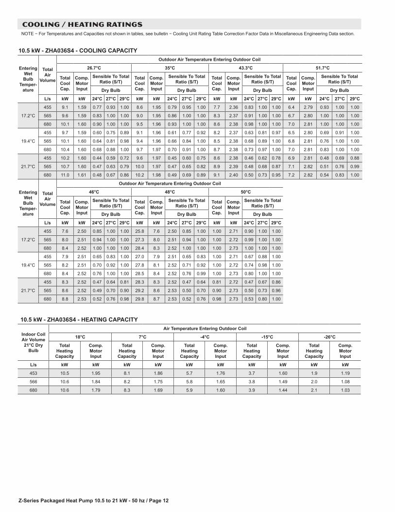
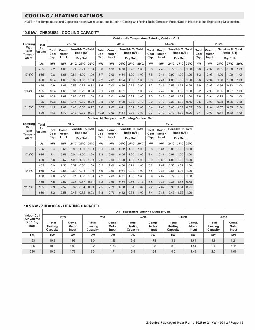
COOLING / HEATING RATINGSNOTE − For Temperatures and Capacities not shown in tables, see bulletin − Cooling Unit Rating Table Correction Factor Data in Miscellaneous Engineering Data section.
10.5 kW - ZHA036S4 - HEATING CAPACITY
Indoor Coil Air Volume 21°C Dry
Bulb
Air Temperature Entering Outdoor Coil
18°C 7°C -4°C -15°C -26°C
Total Heating Capacity
Comp. Motor Input
Total Heating Capacity
Comp. Motor Input
Total Heating Capacity
Comp. Motor Input
Total Heating Capacity
Comp. Motor Input
Total Heating Capacity
Comp. Motor Input
L/s kW kW kW kW kW kW kW kW kW kW
453 10.5 1.95 8.1 1.86 5.7 1.76 3.7 1.60 1.9 1.19
566 10.6 1.84 8.2 1.75 5.8 1.65 3.8 1.49 2.0 1.08
680 10.6 1.79 8.3 1.69 5.9 1.60 3.9 1.44 2.1 1.03
10.5 kW - ZHA036S4 - COOLING CAPACITY
Entering Wet Bulb
Temper-ature
Total Air
Volume
Outdoor Air Temperature Entering Outdoor Coil
26.7°C 35°C 43.3°C 51.7°C
Total Cool Cap.
Comp. Motor Input
Sensible To Total Ratio (S/T)
Total Cool Cap.
Comp. Motor Input
Sensible To Total Ratio (S/T)
Total Cool Cap.
Comp. Motor Input
Sensible To Total Ratio (S/T)
Total Cool Cap.
Comp. Motor Input
Sensible To Total Ratio (S/T)
Dry Bulb Dry Bulb Dry Bulb Dry Bulb
L/s kW kW 24°C 27°C 29°C kW kW 24°C 27°C 29°C kW kW 24°C 27°C 29°C kW kW 24°C 27°C 29°C
17.2°C
455 9.1 1.59 0.77 0.93 1.00 8.6 1.95 0.79 0.95 1.00 7.7 2.36 0.83 1.00 1.00 6.4 2.79 0.93 1.00 1.00
565 9.6 1.59 0.83 1.00 1.00 9.0 1.95 0.86 1.00 1.00 8.3 2.37 0.91 1.00 1.00 6.7 2.80 1.00 1.00 1.00
680 10.1 1.60 0.90 1.00 1.00 9.5 1.96 0.93 1.00 1.00 8.6 2.38 0.98 1.00 1.00 7.0 2.81 1.00 1.00 1.00
19.4°C
455 9.7 1.59 0.60 0.75 0.89 9.1 1.96 0.61 0.77 0.92 8.2 2.37 0.63 0.81 0.97 6.5 2.80 0.69 0.91 1.00
565 10.1 1.60 0.64 0.81 0.98 9.4 1.96 0.66 0.84 1.00 8.5 2.38 0.68 0.89 1.00 6.8 2.81 0.76 1.00 1.00
680 10.4 1.60 0.68 0.88 1.00 9.7 1.97 0.70 0.91 1.00 8.7 2.38 0.73 0.97 1.00 7.0 2.81 0.83 1.00 1.00
21.7°C
455 10.2 1.60 0.44 0.59 0.72 9.6 1.97 0.45 0.60 0.75 8.6 2.38 0.46 0.62 0.78 6.9 2.81 0.48 0.69 0.88
565 10.7 1.60 0.47 0.63 0.79 10.0 1.97 0.47 0.65 0.82 8.9 2.39 0.48 0.68 0.87 7.1 2.82 0.51 0.76 0.99
680 11.0 1.61 0.48 0.67 0.86 10.2 1.98 0.49 0.69 0.89 9.1 2.40 0.50 0.73 0.95 7.2 2.82 0.54 0.83 1.00
Entering Wet Bulb
Temper-ature
Total Air
Volume
Outdoor Air Temperature Entering Outdoor Coil
46°C 48°C 50°C
Total Cool Cap.
Comp. Motor Input
Sensible To Total Ratio (S/T)
Total Cool Cap.
Comp. Motor Input
Sensible To Total Ratio (S/T)
Total Cool Cap.
Comp. Motor Input
Sensible To Total Ratio (S/T)
Dry Bulb Dry Bulb Dry Bulb
L/s kW kW 24°C 27°C 29°C kW kW 24°C 27°C 29°C kW kW 24°C 27°C 29°C
17.2°C
455 7.6 2.50 0.85 1.00 1.00 25.8 7.6 2.50 0.85 1.00 1.00 2.71 0.90 1.00 1.00
565 8.0 2.51 0.94 1.00 1.00 27.3 8.0 2.51 0.94 1.00 1.00 2.72 0.99 1.00 1.00
680 8.4 2.52 1.00 1.00 1.00 28.4 8.3 2.52 1.00 1.00 1.00 2.73 1.00 1.00 1.00
19.4°C
455 7.9 2.51 0.65 0.83 1.00 27.0 7.9 2.51 0.65 0.83 1.00 2.71 0.67 0.88 1.00
565 8.2 2.51 0.70 0.92 1.00 27.8 8.1 2.52 0.71 0.92 1.00 2.72 0.74 0.98 1.00
680 8.4 2.52 0.76 1.00 1.00 28.5 8.4 2.52 0.76 0.99 1.00 2.73 0.80 1.00 1.00
21.7°C
455 8.3 2.52 0.47 0.64 0.81 28.3 8.3 2.52 0.47 0.64 0.81 2.72 0.47 0.67 0.86
565 8.6 2.52 0.49 0.70 0.90 29.2 8.6 2.53 0.50 0.70 0.90 2.73 0.50 0.73 0.96
680 8.8 2.53 0.52 0.76 0.98 29.8 8.7 2.53 0.52 0.76 0.98 2.73 0.53 0.80 1.00

Z-Series Packaged Heat Pump 10.5 to 21 kW - 50 hz / Page 13
14.0 KW - ZHA048S4 - HEATING CAPACITY
Indoor Coil Air Volume 21°C Dry
Bulb
Air Temperature Entering Outdoor Coil
18°C 7°C -4°C -15°C -26°C
Total Heating Capacity
Comp. Motor Input
Total Heating Capacity
Comp. Motor Input
Total Heating Capacity
Comp. Motor Input
Total Heating Capacity
Comp. Motor Input
Total Heating Capacity
Comp. Motor Input
L/s kW kW kW kW kW kW kW kW kW kW
604 13.7 2.56 10.6 2.44 7.5 2.31 5.0 2.12 2.5 1.57
755 13.9 2.43 10.8 2.31 7.7 2.18 5.2 1.99 2.7 1.44
906 14.1 2.36 11.0 2.24 7.9 2.11 5.4 1.92 2.9 1.37
COOLING / HEATING RATINGSNOTE − For Temperatures and Capacities not shown in tables, see bulletin − Cooling Unit Rating Table Correction Factor Data in Miscellaneous Engineering Data section.
14.0 KW - ZHA048S4 - COOLING CAPACITY
Entering Wet Bulb
Temper-ature
Total Air
Volume
Outdoor Air Temperature Entering Outdoor Coil
26.7°C 35°C 43.3°C 51.7°C
Total Cool Cap.
Comp. Motor Input
Sensible To Total Ratio (S/T)
Total Cool Cap.
Comp. Motor Input
Sensible To Total Ratio (S/T)
Total Cool Cap.
Comp. Motor Input
Sensible To Total Ratio (S/T)
Total Cool Cap.
Comp. Motor Input
Sensible To Total Ratio (S/T)
Dry Bulb Dry Bulb Dry Bulb Dry Bulb
L/s kW kW 24°C 27°C 29°C kW kW 24°C 27°C 29°C kW kW 24°C 27°C 29°C kW kW 24°C 27°C 29°C
17.2°C
605 12.5 2.34 0.77 0.93 1.00 10.6 2.81 0.79 0.97 1.00 8.8 3.41 0.81 1.00 1.00 6.9 4.18 0.88 1.00 1.00
755 13.3 2.35 0.84 1.00 1.00 11.5 2.83 0.87 1.00 1.00 9.7 3.44 0.92 1.00 1.00 7.6 4.21 0.99 1.00 1.00
905 14.1 2.37 0.91 1.00 1.00 12.3 2.85 0.94 1.00 1.00 10.4 3.46 0.99 1.00 1.00 8.2 4.23 1.00 1.00 1.00
19.4°C
605 13.5 2.35 0.58 0.75 0.90 11.5 2.83 0.57 0.77 0.94 9.6 3.43 0.56 0.79 0.98 7.3 4.19 0.55 0.86 1.00
755 14.2 2.37 0.63 0.82 0.98 12.2 2.85 0.63 0.85 1.00 10.1 3.45 0.64 0.90 1.00 7.8 4.21 0.65 0.97 1.00
905 14.7 2.38 0.68 0.89 1.00 12.7 2.86 0.69 0.93 1.00 10.5 3.47 0.71 0.98 1.00 8.3 4.23 0.75 1.00 1.00
21.7°C
605 14.5 2.37 0.42 0.58 0.73 12.5 2.86 0.39 0.57 0.75 10.5 3.46 0.35 0.57 0.77 8.1 4.22 0.29 0.57 0.84
755 15.2 2.39 0.45 0.63 0.81 13.2 2.87 0.42 0.63 0.83 11.0 3.48 0.39 0.64 0.88 8.6 4.25 0.34 0.67 0.95
905 15.8 2.41 0.47 0.67 0.87 13.7 2.89 0.45 0.69 0.91 11.4 3.50 0.42 0.71 0.96 8.9 4.26 0.39 0.76 1.00
Entering Wet Bulb
Temper-ature
Total Air
Volume
Outdoor Air Temperature Entering Outdoor Coil
46°C 48°C 50°C
Total Cool Cap.
Comp. Motor Input
Sensible To Total Ratio (S/T)
Total Cool Cap.
Comp. Motor Input
Sensible To Total Ratio (S/T)
Total Cool Cap.
Comp. Motor Input
Sensible To Total Ratio (S/T)
Dry Bulb Dry Bulb Dry Bulb
L/s kW kW 24°C 27°C 29°C kW kW 24°C 27°C 29°C kW kW 24°C 27°C 29°C
17.2°C
605 8.2 3.63 0.81 1.00 1.00 27.9 8.2 3.64 0.81 1.00 1.00 4.01 0.86 1.00 1.00
755 9.1 3.66 0.93 1.00 1.00 31.0 9.1 3.67 0.93 1.00 1.00 4.04 0.97 1.00 1.00
905 9.8 3.68 1.00 1.00 1.00 33.3 9.8 3.69 1.00 1.00 1.00 4.06 1.00 1.00 1.00
19.4°C
605 8.9 3.65 0.55 0.79 1.00 30.3 8.9 3.66 0.55 0.79 1.00 4.03 0.58 0.84 1.00
755 9.4 3.67 0.63 0.90 1.00 32.0 9.4 3.68 0.63 0.91 1.00 4.04 0.65 0.96 1.00
905 9.8 3.68 0.70 0.99 1.00 33.4 9.8 3.69 0.70 0.99 1.00 4.06 0.74 1.00 1.00
21.7°C
605 9.8 3.68 0.33 0.55 0.77 33.3 9.8 3.69 0.33 0.55 0.77 4.06 0.30 0.56 0.82
755 10.3 3.70 0.37 0.63 0.88 35.1 10.3 3.71 0.37 0.63 0.88 4.08 0.35 0.66 0.93
905 10.7 3.72 0.41 0.71 0.97 36.2 10.6 3.72 0.41 0.71 0.98 4.10 0.40 0.75 1.00

Z-Series Packaged Heat Pump 10.5 to 21 kW - 50 hz / Page 14
COOLING / HEATING RATINGSNOTE − For Temperatures and Capacities not shown in tables, see bulletin − Cooling Unit Rating Table Correction Factor Data in Miscellaneous Engineering Data section.
17.5 KW - ZHA060S4 - COOLING CAPACITY
Indoor Coil Air Volume
70°F Dry Bulb
Air Temperature Entering Outdoor Coil
18°C 7°C -4°C -15°C -26°C
Total Heating Capacity
Comp. Motor Input
Total Heating Capacity
Comp. Motor Input
Total Heating Capacity
Comp. Motor Input
Total Heating Capacity
Comp. Motor Input
Total Heating Capacity
Comp. Motor Input
L/s kW kW kW kW kW kW kW kW kW kW
755 18.3 3.31 13.8 3.12 9.2 2.92 5.9 2.64 3.0 1.95
944 18.5 3.18 14.0 2.98 9.4 2.79 6.2 2.50 3.3 1.81
1133 18.7 3.11 14.2 2.92 9.6 2.72 6.3 2.43 3.4 1.74
17.5 KW - ZHA060S4 - COOLING CAPACITY
Entering Wet Bulb
Temper-ature
Total Air
Volume
Outdoor Air Temperature Entering Outdoor Coil
26.7°C 35°C 43.3°C 51.7°C
Total Cool Cap.
Comp. Motor Input
Sensible To Total Ratio (S/T)
Total Cool Cap.
Comp. Motor Input
Sensible To Total Ratio (S/T)
Total Cool Cap.
Comp. Motor Input
Sensible To Total Ratio (S/T)
Total Cool Cap.
Comp. Motor Input
Sensible To Total Ratio (S/T)
Dry Bulb Dry Bulb Dry Bulb Dry Bulb
L/s kW kW 24°C 27°C 29°C kW kW 24°C 27°C 29°C kW kW 24°C 27°C 29°C kW kW 24°C 27°C 29°C
17.2°C
755 15.6 2.89 0.77 0.93 1.00 13.5 3.46 0.79 0.96 1.00 11.3 4.19 0.82 1.00 1.00 9.2 5.18 0.87 1.00 1.00
944 16.5 2.91 0.84 1.00 1.00 14.6 3.49 0.87 1.00 1.00 12.4 4.23 0.91 1.00 1.00 10.2 5.23 0.98 1.00 1.00
1133 17.6 2.93 0.90 1.00 1.00 15.6 3.51 0.94 1.00 1.00 13.3 4.26 0.99 1.00 1.00 11.0 5.26 1.00 1.00 1.00
19.4°C
755 16.8 2.91 0.58 0.75 0.90 14.7 3.49 0.58 0.76 0.93 12.3 4.22 0.57 0.80 0.98 9.8 5.20 0.57 0.85 1.00
944 17.7 2.93 0.63 0.82 0.98 15.5 3.51 0.63 0.85 1.00 12.9 4.24 0.64 0.90 1.00 10.4 5.23 0.66 0.96 1.00
1133 18.4 2.95 0.68 0.89 1.00 16.1 3.53 0.68 0.92 1.00 13.4 4.26 0.71 0.97 1.00 11.0 5.26 0.74 1.00 1.00
21.7°C
755 18.0 2.94 0.42 0.58 0.73 15.9 3.52 0.40 0.57 0.74 13.4 4.26 0.37 0.57 0.77 10.8 5.25 0.32 0.58 0.82
944 19.0 2.96 0.45 0.63 0.80 16.7 3.54 0.43 0.63 0.83 14.0 4.28 0.40 0.64 0.88 11.4 5.28 0.37 0.67 0.94
1133 19.7 2.97 0.47 0.67 0.87 17.2 3.56 0.45 0.68 0.90 14.6 4.30 0.44 0.71 0.95 11.8 5.31 0.41 0.75 1.00
Entering Wet Bulb
Temper-ature
Total Air
Volume
Outdoor Air Temperature Entering Outdoor Coil
46°C 48°C 50°C
Total Cool Cap.
Comp. Motor Input
Sensible To Total Ratio (S/T)
Total Cool Cap.
Comp. Motor Input
Sensible To Total Ratio (S/T)
Total Cool Cap.
Comp. Motor Input
Sensible To Total Ratio (S/T)
Dry Bulb Dry Bulb Dry Bulb
L/s kW kW 24°C 27°C 29°C kW kW 24°C 27°C 29°C kW kW 24°C 27°C 29°C
17.2°C
755 14.1 4.47 0.86 1.00 1.00 14.1 4.47 0.86 1.00 1.00 9.6 4.95 0.86 1.00 1.00
945 14.9 4.52 0.94 1.00 1.00 14.9 4.52 0.94 1.00 1.00 10.6 4.99 0.96 1.00 1.00
1135 15.6 4.54 1.00 1.00 1.00 15.6 4.54 1.00 1.00 1.00 11.4 5.03 1.00 1.00 1.00
19.4°C
755 14.7 4.50 0.66 0.84 1.00 14.7 4.50 0.66 0.84 1.00 10.3 4.97 0.57 0.83 1.00
945 15.2 4.53 0.71 0.92 1.00 15.2 4.53 0.71 0.92 1.00 10.9 5.00 0.65 0.94 1.00
1135 15.6 4.55 0.76 0.99 1.00 15.6 4.55 0.76 0.99 1.00 11.4 5.03 0.74 1.00 1.00
21.7°C
755 15.5 4.54 0.47 0.65 0.81 15.5 4.54 0.47 0.65 0.81 11.3 5.02 0.33 0.58 0.81
945 16.1 4.57 0.50 0.70 0.90 16.1 4.57 0.50 0.70 0.90 12.0 5.05 0.38 0.66 0.92
1135 16.4 4.59 0.52 0.76 0.98 16.4 4.59 0.52 0.76 0.98 12.3 5.07 0.42 0.74 1.00
Z-Series Packaged Heat Pump 10.5 to 21 kW - 50 hz / Page 15
10.5 kW - ZHB036S4 - HEATING CAPACITY
Indoor Coil Air Volume 21°C Dry
Bulb
Air Temperature Entering Outdoor Coil
18°C 7°C -4°C -15°C -26°C
Total Heating Capacity
Comp. Motor Input
Total Heating Capacity
Comp. Motor Input
Total Heating Capacity
Comp. Motor Input
Total Heating Capacity
Comp. Motor Input
Total Heating Capacity
Comp. Motor Input
L/s kW kW kW kW kW kW kW kW kW kW
453 10.3 1.93 8.0 1.86 5.6 1.78 3.8 1.64 1.9 1.21
566 10.5 1.83 8.2 1.76 5.8 1.68 3.9 1.54 2.0 1.11
680 10.6 1.78 8.3 1.71 5.9 1.64 4.0 1.49 2.2 1.06
COOLING / HEATING RATINGSNOTE − For Temperatures and Capacities not shown in tables, see bulletin − Cooling Unit Rating Table Correction Factor Data in Miscellaneous Engineering Data section.
10.5 kW - ZHB036S4 - COOLING CAPACITY
Entering Wet Bulb
Temper-ature
Total Air
Volume
Outdoor Air Temperature Entering Outdoor Coil
26.7°C 35°C 43.3°C 51.7°C
Total Cool Cap.
Comp. Motor Input
Sensible To Total Ratio (S/T)
Total Cool Cap.
Comp. Motor Input
Sensible To Total Ratio (S/T)
Total Cool Cap.
Comp. Motor Input
Sensible To Total Ratio (S/T)
Total Cool Cap.
Comp. Motor Input
Sensible To Total Ratio (S/T)
Dry Bulb Dry Bulb Dry Bulb Dry Bulb
L/s kW kW 24°C 27°C 29°C kW kW 24°C 27°C 29°C kW kW 24°C 27°C 29°C kW kW 24°C 27°C 29°C
17.2°C
455 9.2 1.66 0.74 0.91 1.00 8.0 1.99 0.76 0.96 1.00 6.8 2.40 0.79 1.00 1.00 5.6 2.92 0.85 1.00 1.00
565 9.8 1.66 0.81 1.00 1.00 8.7 2.00 0.84 1.00 1.00 7.5 2.41 0.90 1.00 1.00 6.2 2.93 1.00 1.00 1.00
680 10.4 1.68 0.89 1.00 1.00 9.2 2.01 0.94 1.00 1.00 8.0 2.41 1.00 1.00 1.00 6.6 2.94 1.00 1.00 1.00
19.4°C
455 9.9 1.66 0.56 0.72 0.88 8.6 2.00 0.56 0.74 0.92 7.3 2.41 0.56 0.77 0.99 5.9 2.93 0.56 0.82 1.00
565 10.4 1.68 0.61 0.79 0.98 9.1 2.00 0.61 0.82 1.00 7.7 2.42 0.62 0.88 1.00 6.2 2.93 0.65 0.97 1.00
680 10.8 1.68 0.65 0.87 1.00 9.4 2.01 0.66 0.91 1.00 8.0 2.42 0.69 0.98 1.00 6.6 2.94 0.73 1.00 1.00
21.7°C
455 10.6 1.68 0.41 0.55 0.70 9.3 2.01 0.39 0.55 0.72 8.0 2.42 0.36 0.56 0.75 6.5 2.93 0.33 0.56 0.80
565 11.2 1.69 0.43 0.60 0.77 9.8 2.02 0.41 0.61 0.80 8.4 2.43 0.40 0.62 0.85 6.9 2.94 0.37 0.65 0.94
680 11.5 1.70 0.45 0.65 0.84 10.2 2.02 0.44 0.66 0.89 8.7 2.43 0.43 0.69 0.96 7.1 2.93 0.41 0.73 1.00
Entering Wet Bulb
Temper-ature
Total Air
Volume
Outdoor Air Temperature Entering Outdoor Coil
46°C 48°C 50°C
Total Cool Cap.
Comp. Motor Input
Sensible To Total Ratio (S/T)
Total Cool Cap.
Comp. Motor Input
Sensible To Total Ratio (S/T)
Total Cool Cap.
Comp. Motor Input
Sensible To Total Ratio (S/T)
Dry Bulb Dry Bulb Dry Bulb
L/s kW kW 24°C 27°C 29°C kW kW 24°C 27°C 29°C kW kW 24°C 27°C 29°C
17.2°C
455 6.4 2.55 0.82 1.00 1.00 6.1 2.68 0.82 1.00 1.00 5.8 2.81 0.83 1.00 1.00
565 7.1 2.56 0.94 1.00 1.00 6.8 2.69 0.95 1.00 1.00 6.4 2.81 0.97 1.00 1.00
680 7.6 2.57 1.00 1.00 1.00 7.2 2.69 1.00 1.00 1.00 6.9 2.83 1.00 1.00 1.00
19.4°C
455 6.9 2.56 0.57 0.80 1.00 6.5 2.69 0.56 0.79 1.00 6.2 2.82 0.56 0.81 1.00
565 7.3 2.56 0.64 0.91 1.00 6.9 2.69 0.64 0.92 1.00 6.5 2.81 0.64 0.94 1.00
680 7.6 2.56 0.71 1.00 1.00 7.2 2.69 0.71 1.00 1.00 6.9 2.82 0.72 1.00 1.00
21.7°C
455 7.5 2.57 0.36 0.57 0.77 7.2 2.69 0.34 0.56 0.77 6.8 2.81 0.34 0.56 0.78
565 7.9 2.57 0.39 0.64 0.89 7.5 2.70 0.38 0.64 0.89 7.2 2.82 0.38 0.64 0.91
680 8.2 2.58 0.43 0.72 0.98 7.8 2.70 0.42 0.71 1.00 7.4 2.83 0.42 0.72 1.00

Z-Series Packaged Heat Pump 10.5 to 21 kW - 50 hz / Page 16
14.0 KW - ZHB048S4 - HEATING CAPACITY
Indoor Coil Air Volume 21°C Dry
Bulb
Air Temperature Entering Outdoor Coil
18°C 7°C -4°C -15°C -26°C
Total Heating Capacity
Comp. Motor Input
Total Heating Capacity
Comp. Motor Input
Total Heating Capacity
Comp. Motor Input
Total Heating Capacity
Comp. Motor Input
Total Heating Capacity
Comp. Motor Input
L/s kW kW kW kW kW kW kW kW kW kW
604 12.8 2.76 10.9 2.48 9.1 2.19 6.5 1.93 3.1 1.46
755 13 2.61 11.1 2.33 9.3 2.04 6.7 1.78 3.3 1.31
906 13.2 2.52 11.3 2.24 9.6 1.95 6.9 1.69 3.5 1.22
COOLING / HEATING RATINGSNOTE − For Temperatures and Capacities not shown in tables, see bulletin − Cooling Unit Rating Table Correction Factor Data in Miscellaneous Engineering Data section.
14.0 KW - ZHB048S4 - COOLING CAPACITY
Entering Wet Bulb
Temper-ature
Total Air
Volume
Outdoor Air Temperature Entering Outdoor Coil
26.7°C 35°C 43.3°C 51.7°C
Total Cool Cap.
Comp. Motor Input
Sensible To Total Ratio (S/T)
Total Cool Cap.
Comp. Motor Input
Sensible To Total Ratio (S/T)
Total Cool Cap.
Comp. Motor Input
Sensible To Total Ratio (S/T)
Total Cool Cap.
Comp. Motor Input
Sensible To Total Ratio (S/T)
Dry Bulb Dry Bulb Dry Bulb Dry Bulb
L/s kW kW 24°C 27°C 29°C kW kW 24°C 27°C 29°C kW kW 24°C 27°C 29°C kW kW 24°C 27°C 29°C
17.2°C
605 12.1 2.28 0.73 0.90 1.00 10.7 2.76 0.74 0.95 1.00 9.1 3.36 0.8 1.00 1.00 7.5 4.11 0.84 1.00 1.00
755 12.9 2.28 0.79 1.00 1.00 11.5 2.78 0.82 1.00 1.00 10 3.37 0.9 1.00 1.00 8.2 4.12 0.98 1.00 1.00
905 13.7 2.29 0.87 1.00 1.00 12.2 2.78 0.92 1.00 1.00 10.7 3.39 1.0 1.00 1.00 8.8 4.14 1.00 1.00 1.00
19.4°C
605 13.0 2.28 0.56 0.71 0.86 11.5 2.78 0.55 0.72 0.91 9.8 3.36 0.6 0.75 0.97 7.9 4.12 0.56 0.81 1.00
755 13.7 2.28 0.60 0.77 0.97 12.1 2.79 0.61 0.80 1.00 10.3 3.37 0.6 0.85 1.00 8.4 4.14 0.64 0.95 1.00
905 14.2 2.28 0.64 0.84 1.00 12.5 2.78 0.65 0.89 1.00 10.8 3.39 0.7 0.96 1.00 8.8 4.13 0.72 1.00 1.00
21.7°C
605 13.9 2.28 0.41 0.55 0.68 12.3 2.79 0.38 0.55 0.70 10.7 3.38 0.4 0.55 0.73 8.6 4.12 0.34 0.56 0.78
755 14.6 2.29 0.43 0.59 0.75 13.0 2.80 0.41 0.60 0.78 11.2 3.39 0.4 0.61 0.83 9.1 4.13 0.38 0.64 0.92
905 15.1 2.29 0.45 0.64 0.82 13.4 2.79 0.44 0.65 0.86 11.5 3.41 0.4 0.67 0.93 9.4 4.13 0.42 0.72 1.00
Entering Wet Bulb
Temper-ature
Total Air
Volume
Outdoor Air Temperature Entering Outdoor Coil
46°C 48°C 50°C
Total Cool Cap.
Comp. Motor Input
Sensible To Total Ratio (S/T)
Total Cool Cap.
Comp. Motor Input
Sensible To Total Ratio (S/T)
Total Cool Cap.
Comp. Motor Input
Sensible To Total Ratio (S/T)
Dry Bulb Dry Bulb Dry Bulb
L/s kW kW 24°C 27°C 29°C kW kW 24°C 27°C 29°C kW kW 24°C 27°C 29°C
17.2°C
605 8.6 3.58 0.81 1.00 1.00 8.30 3.76 0.80 1.00 1.00 7.90 3.95 0.82 1.00 1.00
755 9.5 3.59 0.92 1.00 1.00 9.10 3.77 0.93 1.00 1.00 8.60 3.96 0.96 1.00 1.00
905 10.1 3.61 1.00 1.00 1.00 9.70 3.79 1.00 1.00 1.00 9.20 3.98 1.00 1.00 1.00
19.4°C
605 9.3 3.59 0.57 0.79 0.99 8.80 3.77 0.56 0.78 1.00 8.30 3.95 0.56 0.79 1.00
755 9.8 3.59 0.63 0.89 1.00 9.30 3.77 0.63 0.90 1.00 8.80 3.96 0.63 0.93 1.00
905 10.2 3.61 0.70 0.99 1.00 9.70 3.78 0.69 1.00 1.00 9.20 3.95 0.71 1.00 1.00
21.7°C
605 10.1 3.59 0.36 0.56 0.76 9.60 3.78 0.35 0.56 0.76 9.10 3.97 0.34 0.56 0.77
755 10.6 3.61 0.40 0.64 0.87 10.10 3.78 0.38 0.63 0.87 9.50 3.97 0.38 0.64 0.89
905 10.9 3.62 0.43 0.70 0.96 10.40 3.80 0.42 0.70 0.98 9.80 3.99 0.42 0.71 1.00

Z-Series Packaged Heat Pump 10.5 to 21 kW - 50 hz / Page 17
COOLING / HEATING RATINGSNOTE − For Temperatures and Capacities not shown in tables, see bulletin − Cooling Unit Rating Table Correction Factor Data in Miscellaneous Engineering Data section.
17.5 KW - ZHB060S4 - HEATING CAPACITY
Indoor Coil Air Volume
70°F Dry Bulb
Air Temperature Entering Outdoor Coil
18°C 7°C -4°C -15°C -26°C
Total Heating Capacity
Comp. Motor Input
Total Heating Capacity
Comp. Motor Input
Total Heating Capacity
Comp. Motor Input
Total Heating Capacity
Comp. Motor Input
Total Heating Capacity
Comp. Motor Input
L/s kW kW kW kW kW kW kW kW kW kW
755 15.5 2.96 13.3 2.85 11.1 2.74 8.0 2.53 3.8 1.87
944 15.7 2.80 13.5 2.69 11.4 2.58 8.2 2.37 4.1 1.71
1133 16.0 2.70 13.7 2.59 11.6 2.48 8.4 2.27 4.3 1.61
17.5 KW - ZHB060S4 - COOLING CAPACITY
Entering Wet Bulb
Temper-ature
Total Air
Volume
Outdoor Air Temperature Entering Outdoor Coil
26.7°C 35°C 43.3°C 51.7°C
Total Cool Cap.
Comp. Motor Input
Sensible To Total Ratio (S/T)
Total Cool Cap.
Comp. Motor Input
Sensible To Total Ratio (S/T)
Total Cool Cap.
Comp. Motor Input
Sensible To Total Ratio (S/T)
Total Cool Cap.
Comp. Motor Input
Sensible To Total Ratio (S/T)
Dry Bulb Dry Bulb Dry Bulb Dry Bulb
L/s kW kW 24°C 27°C 29°C kW kW 24°C 27°C 29°C kW kW 24°C 27°C 29°C kW kW 24°C 27°C 29°C
17.2°C
755 15.2 2.83 0.7 0.92 1.00 12.5 3.40 0.73 0.95 1.00 9.8 4.14 0.74 1.00 1.00 7.1 5.11 0.78 1.00 1.00
944 16.5 2.85 0.8 1.00 1.00 13.9 3.42 0.83 1.00 1.00 11.3 4.16 0.87 1.00 1.00 8.3 5.15 0.96 1.00 1.00
1133 17.8 2.87 0.9 1.00 1.00 15.1 3.44 0.92 1.00 1.00 12.3 4.20 0.98 1.00 1.00 9.3 5.19 1.00 1.00 1.00
19.4°C
755 16.7 2.85 0.5 0.71 0.88 14.0 3.42 0.51 0.71 0.91 11.0 4.17 0.47 0.73 0.97 7.8 5.11 0.39 0.76 1.00
944 17.8 2.87 0.6 0.79 0.97 14.9 3.44 0.58 0.81 1.00 11.8 4.17 0.56 0.85 1.00 8.6 5.15 0.53 0.93 1.00
1133 18.6 2.88 0.6 0.86 1.00 15.6 3.45 0.63 0.89 1.00 12.5 4.20 0.63 0.96 1.00 9.3 5.18 0.63 1.00 1.00
21.7°C
755 18.3 2.87 0.4 0.54 0.69 15.4 3.45 0.33 0.52 0.70 12.4 4.19 0.25 0.49 0.71 9.1 5.16 0.12 0.44 0.74
944 19.4 2.89 0.4 0.59 0.77 16.4 3.46 0.37 0.58 0.79 13.2 4.21 0.30 0.57 0.83 9.7 5.19 0.19 0.56 0.90
1133 20.1 2.90 0.4 0.64 0.84 17.0 3.47 0.40 0.64 0.87 13.8 4.23 0.35 0.64 0.93 10.3 5.22 0.26 0.66 1.00
Entering Wet Bulb
Temper-ature
Total Air
Volume
Outdoor Air Temperature Entering Outdoor Coil
46°C 48°C 50°C
Total Cool Cap.
Comp. Motor Input
Sensible To Total Ratio (S/T)
Total Cool Cap.
Comp. Motor Input
Sensible To Total Ratio (S/T)
Total Cool Cap.
Comp. Motor Input
Sensible To Total Ratio (S/T)
Dry Bulb Dry Bulb Dry Bulb
L/s kW kW 24°C 27°C 29°C kW kW 24°C 27°C 29°C kW kW 24°C 27°C 29°C
17.2°C
755 9.0 4.42 0.75 1.00 1.00 8.3 4.65 0.76 1.00 1.00 7.60 4.90 0.76 1.00 1.00
945 10.3 4.44 0.90 1.00 1.00 9.6 4.69 0.92 1.00 1.00 8.90 4.93 0.94 1.00 1.00
1135 11.4 4.48 1.00 1.00 1.00 10.6 4.71 1.00 1.00 1.00 9.90 4.96 1.00 1.00 1.00
19.4°C
755 10.0 4.44 0.45 0.74 1.00 9.2 4.68 0.43 0.74 1.00 8.40 4.90 0.41 0.75 1.00
945 10.8 4.45 0.55 0.87 1.00 10.0 4.70 0.54 0.89 1.00 9.20 4.94 0.53 0.91 1.00
1135 11.5 4.48 0.63 0.98 1.00 10.7 4.72 0.63 1.00 1.00 9.90 4.96 0.63 1.00 1.00
21.7°C
755 11.4 4.48 0.22 0.47 0.72 10.6 4.72 0.19 0.46 0.73 9.70 4.94 0.15 0.45 0.73
945 12.1 4.49 0.28 0.57 0.85 11.3 4.72 0.25 0.56 0.86 10.50 4.98 0.22 0.56 0.88
1135 12.7 4.51 0.32 0.65 0.95 11.8 4.75 0.30 0.65 0.97 11.00 5.00 0.28 0.65 0.99

Z-Series Packaged Heat Pump 10.5 to 21 kW - 50 hz / Page 18
COOLING / HEATING RATINGSNOTE − For Temperatures and Capacities not shown in tables, see bulletin − Cooling Unit Rating Table Correction Factor Data in Miscellaneous Engineering Data section.
21.0 KW - ZHB072S4 - HEATING CAPACITY
Indoor Coil Air Volume
70°F Dry Bulb
Air Temperature Entering Outdoor Coil
18°C 7°C -4°C -15°C -26°C
Total Heating Capacity
Comp. Motor Input
Total Heating Capacity
Comp. Motor Input
Total Heating Capacity
Comp. Motor Input
Total Heating Capacity
Comp. Motor Input
Total Heating Capacity
Comp. Motor Input
L/s kW kW kW kW kW kW kW kW kW kW
850 22.1 4.47 16.9 4.1 11.8 3.72 7.1 3.26 3.6 2.45
1085 22.4 4.26 17.2 3.89 12.1 3.52 7.4 3.05 3.9 2.24
1320 22.6 4.16 17.5 3.78 12.3 3.41 7.6 2.95 4.2 2.13
21.0 KW - ZHB072S4 - COOLING CAPACITY
Entering Wet Bulb
Temper-ature
Total Air
Volume
Outdoor Air Temperature Entering Outdoor Coil
26.7°C 35°C 43.3°C 51.7°C
Total Cool Cap.
Comp. Motor Input
Sensible To Total Ratio (S/T)
Total Cool Cap.
Comp. Motor Input
Sensible To Total Ratio (S/T)
Total Cool Cap.
Comp. Motor Input
Sensible To Total Ratio (S/T)
Total Cool Cap.
Comp. Motor Input
Sensible To Total Ratio (S/T)
Dry Bulb Dry Bulb Dry Bulb Dry Bulb
L/s kW kW 24°C 27°C 29°C kW kW 24°C 27°C 29°C kW kW 24°C 27°C 29°C kW kW 24°C 27°C 29°C
17.2°C
850 18.2 3.81 0.74 0.89 1.00 16.4 4.52 0.76 0.92 1.00 14.5 5.39 0.79 0.97 1.00 12.4 6.42 0.84 1.00 1.00
1085 19.3 3.86 0.81 0.97 1.00 17.4 4.57 0.84 1.00 1.00 15.6 5.46 0.88 1.00 1.00 13.4 6.47 0.94 1.00 1.00
1320 20.3 3.89 0.87 1.00 1.00 18.5 4.62 0.90 1.00 1.00 16.4 5.49 0.96 1.00 1.00 14.1 6.51 1.00 1.00 1.00
19.4°C
850 19.4 3.85 0.58 0.72 0.86 17.5 4.57 0.58 0.74 0.89 15.4 5.43 0.59 0.77 0.94 13.0 6.45 0.61 0.82 1.00
1085 20.4 3.89 0.62 0.79 0.94 18.4 4.62 0.63 0.82 0.98 16.2 5.48 0.65 0.86 1.00 13.7 6.48 0.68 0.92 1.00
1320 21.1 3.92 0.66 0.85 1.00 19.0 4.65 0.68 0.89 1.00 16.7 5.50 0.70 0.94 1.00 14.2 6.53 0.74 1.00 1.00
21.7°C
850 20.5 3.89 0.43 0.57 0.70 18.6 4.63 0.42 0.57 0.72 16.4 5.49 0.41 0.58 0.75 14.0 6.50 0.41 0.60 0.80
1085 21.6 3.95 0.45 0.61 0.77 19.5 4.67 0.45 0.62 0.80 17.2 5.52 0.44 0.64 0.84 14.6 6.54 0.44 0.68 0.90
1320 22.3 3.98 0.47 0.65 0.83 20.1 4.70 0.47 0.67 0.87 17.7 5.56 0.47 0.70 0.92 15.0 6.57 0.47 0.74 0.99
Entering Wet Bulb
Temper-ature
Total Air
Volume
Outdoor Air Temperature Entering Outdoor Coil
46°C 48°C 50°C
Total Cool Cap.
Comp. Motor Input
Sensible To Total Ratio (S/T)
Total Cool Cap.
Comp. Motor Input
Sensible To Total Ratio (S/T)
Total Cool Cap.
Comp. Motor Input
Sensible To Total Ratio (S/T)
Dry Bulb Dry Bulb Dry Bulb
L/s kW kW 24°C 27°C 29°C kW kW 24°C 27°C 29°C kW kW 24°C 27°C 29°C
17.2°C
850 13.8 5.70 0.80 0.99 1.00 13.3 5.93 0.81 1.00 1.00 12.8 6.19 0.83 1.00 1.00
1085 14.9 5.76 0.89 1.00 1.00 14.4 6.00 0.91 1.00 1.00 13.9 6.25 0.93 1.00 1.00
1320 15.7 5.80 0.98 1.00 1.00 15.2 6.05 0.99 1.00 1.00 14.7 6.29 1.00 1.00 1.00
19.4°C
850 14.7 5.74 0.60 0.78 0.96 14.2 5.99 0.60 0.79 0.97 13.6 6.22 0.60 0.80 0.99
1085 15.4 5.77 0.66 0.88 1.00 14.8 6.02 0.66 0.89 1.00 14.2 6.26 0.67 0.91 1.00
1320 16.0 5.81 0.71 0.96 1.00 15.4 6.05 0.72 0.97 1.00 14.7 6.29 0.73 0.99 1.00
21.7°C
850 15.7 5.79 0.41 0.59 0.76 15.1 6.03 0.41 0.59 0.77 14.5 6.29 0.41 0.60 0.78
1085 16.4 5.84 0.44 0.65 0.85 15.8 6.08 0.44 0.66 0.87 15.1 6.31 0.44 0.67 0.88
1320 16.9 5.86 0.47 0.71 0.94 16.2 6.09 0.47 0.72 0.96 15.6 6.33 0.47 0.73 0.98

Z-Series Packaged Heat Pump 10.5 to 21 kW - 50 hz / Page 19
BL
OW
ER
DA
TA
- B
ELT
DR
IVE
- Z
HA
03
6 -
DO
WN
FL
OW
BLO
WER
TA
BLE
INC
LUD
ES R
ESIS
TAN
CE
FOR
BA
SE U
NIT
ON
LY W
ITH
DRY
IND
OO
R C
OIL
AN
D A
IR F
ILTE
RS
IN P
LAC
E.
FOR
ALL
UN
ITS
AD
D:
1 - A
ny fa
ctor
y in
stal
led
optio
ns a
ir re
sist
ance
(hea
t sec
tion,
eco
nom
izer
, wet
coi
l, et
c.).
2 - A
ny fi
eld
inst
alle
d ac
cess
orie
s ai
r res
ista
nce
(duc
t res
ista
nce,
diff
user
, etc
.).
See
pag
e 33
for b
low
er m
otor
s an
d dr
ives
and
wet
coi
l and
opt
ions
/acc
esso
ry a
ir re
sist
ance
dat
a.
Air
Volu
me
Exte
rnal
Sta
tic -
Pa (i
n. w
.g.)
25 (0
.10)
50 (0
.20)
75 (0
.30)
100
(0.4
0)12
5 (0
.50)
150
(0.6
0)17
5 (0
.70)
200
(0.8
0)
L/s
cfm
Rev
/m
inkW
BH
PR
ev/
min
kWB
HP
Rev
/m
inkW
BH
PR
ev/
min
kWB
HP
Rev
/m
inkW
BH
PR
ev/
min
kWB
HP
Rev
/m
inkW
BH
PR
ev/
min
kWB
HP
425
900
562
0.12
0.16
629
0.13
0.18
699
0.14
0.19
771
0.15
0.20
840
0.16
0.22
904
0.18
0.24
962
0.19
0.26
1015
0.22
0.29
472
1000
586
0.13
0.18
654
0.15
0.20
725
0.16
0.21
796
0.17
0.23
864
0.19
0.25
927
0.20
0.27
983
0.22
0.30
1034
0.25
0.33
519
1100
612
0.15
0.20
681
0.16
0.22
752
0.18
0.24
823
0.19
0.26
890
0.21
0.28
950
0.23
0.31
1004
0.25
0.34
1054
0.28
0.37
566
1200
641
0.17
0.23
711
0.19
0.25
783
0.20
0.27
852
0.22
0.29
917
0.24
0.32
975
0.26
0.35
1027
0.29
0.39
1074
0.31
0.42
613
1300
673
0.19
0.25
744
0.21
0.28
815
0.22
0.30
882
0.25
0.33
944
0.27
0.36
1000
0.30
0.40
1050
0.33
0.44
1096
0.36
0.48
661
1400
709
0.22
0.29
779
0.24
0.32
849
0.25
0.34
914
0.28
0.37
973
0.31
0.41
1026
0.34
0.45
1074
0.37
0.49
1118
0.40
0.53
708
1500
747
0.25
0.33
816
0.27
0.36
883
0.29
0.39
945
0.31
0.42
1001
0.34
0.46
1052
0.38
0.51
1098
0.41
0.55
1141
0.44
0.59
Air
Volu
me
Exte
rnal
Sta
tic -
Pa (i
n. w
.g.)
225
(0.9
0)25
0 (1
.00)
275
(1.1
0)30
0 (1
.20)
325
(1.3
0)35
0 (1
.40)
375
(1.5
0)40
0 (1
.60)
L/s
cfm
Rev
/m
inkW
BH
PR
ev/
min
kWB
HP
Rev
/m
inkW
BH
PR
ev/
min
kWB
HP
Rev
/m
inkW
BH
PR
ev/
min
kWB
HP
Rev
/m
inkW
BH
PR
ev/
min
kWB
HP
425
900
1065
0.24
0.32
1112
0.26
0.35
1158
0.28
0.38
1202
0.31
0.41
1243
0.33
0.44
1284
0.36
0.48
1323
0.39
0.52
1364
0.41
0.55
472
1000
1082
0.27
0.36
1128
0.29
0.39
1173
0.31
0.42
1216
0.34
0.45
1257
0.37
0.49
1297
0.40
0.53
1336
0.43
0.57
1375
0.45
0.60
519
1100
1100
0.30
0.40
1145
0.33
0.44
1189
0.35
0.47
1231
0.38
0.51
1272
0.40
0.54
1311
0.43
0.58
1349
0.46
0.62
1388
0.49
0.66
566
1200
1119
0.34
0.45
1163
0.37
0.49
1206
0.39
0.52
1247
0.42
0.56
1287
0.45
0.60
1326
0.48
0.64
1364
0.51
0.68
1402
0.54
0.72
613
1300
1139
0.38
0.51
1182
0.41
0.55
1224
0.43
0.58
1265
0.46
0.62
1304
0.49
0.66
1342
0.53
0.71
1379
0.56
0.75
1416
0.59
0.79
661
1400
1160
0.43
0.57
1202
0.46
0.61
1243
0.48
0.65
1283
0.51
0.69
1322
0.54
0.73
1359
0.58
0.78
1396
0.61
0.82
1432
0.65
0.87
708
1500
1182
0.48
0.64
1223
0.51
0.68
1263
0.54
0.72
1303
0.57
0.76
1341
0.60
0.81
1378
0.63
0.85
1414
0.67
0.90
1449
0.70
0.94

Z-Series Packaged Heat Pump 10.5 to 21 kW - 50 hz / Page 20
BL
OW
ER
DA
TA
- B
ELT
DR
IVE
- Z
HA
03
6 -
HO
RIZ
ON
TA
L
BLO
WER
TA
BLE
INC
LUD
ES R
ESIS
TAN
CE
FOR
BA
SE U
NIT
ON
LY W
ITH
DRY
IND
OO
R C
OIL
AN
D A
IR F
ILTE
RS
IN P
LAC
E.
FOR
ALL
UN
ITS
AD
D:
1 - A
ny fa
ctor
y in
stal
led
optio
ns a
ir re
sist
ance
(hea
t sec
tion,
eco
nom
izer
, wet
coi
l, et
c.).
2 - A
ny fi
eld
inst
alle
d ac
cess
orie
s ai
r res
ista
nce
(duc
t res
ista
nce,
diff
user
, etc
.).
See
pag
e 33
for b
low
er m
otor
s an
d dr
ives
and
wet
coi
l and
opt
ions
/acc
esso
ry a
ir re
sist
ance
dat
a.
Air
Volu
me
Exte
rnal
Sta
tic -
Pa (i
n. w
.g.)
25 (0
.10)
50 (0
.20)
75 (0
.30)
100
(0.4
0)12
5 (0
.50)
150
(0.6
0)17
5 (0
.70)
200
(0.8
0)
L/s
cfm
Rev
/m
inkW
BH
PR
ev/
min
kWB
HP
Rev
/m
inkW
BH
PR
ev/
min
kWB
HP
Rev
/m
inkW
BH
PR
ev/
min
kWB
HP
Rev
/m
inkW
BH
PR
ev/
min
kWB
HP
425
900
580
0.10
0.14
649
0.13
0.17
721
0.14
0.19
794
0.16
0.22
868
0.18
0.24
938
0.20
0.27
998
0.22
0.30
1045
0.25
0.33
472
1000
612
0.13
0.17
681
0.14
0.19
752
0.16
0.22
825
0.19
0.25
897
0.20
0.27
963
0.22
0.30
1017
0.25
0.33
1061
0.28
0.37
519
1100
647
0.15
0.20
717
0.17
0.23
788
0.19
0.26
858
0.21
0.28
926
0.23
0.31
986
0.25
0.34
1036
0.28
0.38
1077
0.31
0.41
566
1200
687
0.17
0.23
757
0.19
0.26
826
0.22
0.29
893
0.24
0.32
955
0.26
0.35
1008
0.29
0.39
1054
0.31
0.42
1095
0.34
0.46
613
1300
730
0.20
0.27
798
0.22
0.30
864
0.25
0.33
926
0.28
0.37
982
0.30
0.40
1030
0.33
0.44
1073
0.35
0.47
1116
0.38
0.51
661
1400
775
0.23
0.31
840
0.25
0.34
902
0.28
0.38
959
0.31
0.42
1009
0.34
0.46
1054
0.37
0.50
1096
0.40
0.53
1140
0.42
0.56
708
1500
820
0.27
0.36
881
0.30
0.40
939
0.33
0.44
993
0.37
0.49
1039
0.40
0.53
1082
0.42
0.56
1124
0.44
0.59
1168
0.46
0.62
Air
Volu
me
225
(0.9
0)25
0 (1
.00)
275
(1.1
0)30
0 (1
.20)
325
(1.3
0)35
0 (1
.40)
375
(1.5
0)40
0 (1
.60)
L/s
cfm
Rev
/m
inkW
BH
PR
ev/
min
kWB
HP
Rev
/m
inkW
BH
PR
ev/
min
kWB
HP
Rev
/m
inkW
BH
PR
ev/
min
kWB
HP
Rev
/m
inkW
BH
PR
ev/
min
kWB
HP
425
900
1091
0.27
0.36
1140
0.28
0.38
1188
0.30
0.40
1232
0.32
0.43
1272
0.34
0.46
1309
0.37
0.49
1346
0.40
0.53
1383
0.43
0.57
472
1000
1105
0.30
0.40
1154
0.31
0.42
1201
0.34
0.45
1245
0.35
0.47
1284
0.37
0.50
1321
0.40
0.54
1357
0.43
0.58
1394
0.46
0.62
519
1100
1121
0.33
0.44
1169
0.35
0.47
1216
0.37
0.49
1259
0.39
0.52
1298
0.42
0.56
1335
0.45
0.60
1370
0.48
0.64
1406
0.51
0.69
566
1200
1139
0.37
0.49
1187
0.39
0.52
1234
0.40
0.54
1276
0.43
0.58
1314
0.46
0.62
1350
0.49
0.66
1385
0.53
0.71
1421
0.56
0.75
613
1300
1161
0.40
0.54
1208
0.43
0.57
1254
0.45
0.60
1295
0.48
0.64
1332
0.51
0.69
1366
0.54
0.73
1401
0.58
0.78
1436
0.62
0.83
661
1400
1185
0.44
0.59
1232
0.47
0.63
1276
0.50
0.67
1315
0.53
0.71
1351
0.57
0.76
1384
0.60
0.81
1419
0.64
0.86
1454
0.67
0.90
708
1500
1212
0.49
0.66
1257
0.52
0.70
1299
0.55
0.74
1337
0.59
0.79
1371
0.63
0.84
1404
0.66
0.89
1438
0.70
0.94
1473
0.74
0.99

Z-Series Packaged Heat Pump 10.5 to 21 kW - 50 hz / Page 21
BL
OW
ER
DA
TA
- B
ELT
DR
IVE
- Z
HA
04
8 -
DO
WN
FL
OW
BLO
WER
TA
BLE
INC
LUD
ES R
ESIS
TAN
CE
FOR
BA
SE U
NIT
ON
LY W
ITH
DRY
IND
OO
R C
OIL
AN
D A
IR F
ILTE
RS
IN P
LAC
E.
FOR
ALL
UN
ITS
AD
D:
1 - A
ny fa
ctor
y in
stal
led
optio
ns a
ir re
sist
ance
(hea
t sec
tion,
eco
nom
izer
, wet
coi
l, et
c.).
2 - A
ny fi
eld
inst
alle
d ac
cess
orie
s ai
r res
ista
nce
(duc
t res
ista
nce,
diff
user
, etc
.).
See
pag
e 33
for b
low
er m
otor
s an
d dr
ives
and
wet
coi
l and
opt
ions
/acc
esso
ry a
ir re
sist
ance
dat
a.
Air
Volu
me
Exte
rnal
Sta
tic -
Pa (i
n. w
.g.)
25 (0
.10)
50 (0
.20)
75 (0
.30)
100
(0.4
0)12
5 (0
.50)
150
(0.6
0)17
5 (0
.70)
200
(0.8
0)
L/s
cfm
Rev
/m
inkW
BH
PR
ev/
min
kWB
HP
Rev
/m
inkW
BH
PR
ev/
min
kWB
HP
Rev
/m
inkW
BH
PR
ev/
min
kWB
HP
Rev
/m
inkW
BH
PR
ev/
min
kWB
HP
566
1200
641
0.17
0.23
711
0.19
0.25
783
0.20
0.27
852
0.22
0.29
917
0.24
0.32
975
0.26
0.35
1027
0.29
0.39
1074
0.31
0.42
613
1300
673
0.19
0.25
744
0.21
0.28
815
0.22
0.30
882
0.25
0.33
944
0.27
0.36
1000
0.30
0.40
1050
0.33
0.44
1096
0.36
0.48
661
1400
709
0.22
0.29
779
0.24
0.32
849
0.25
0.34
914
0.28
0.37
973
0.31
0.41
1026
0.34
0.45
1074
0.37
0.49
1118
0.40
0.53
708
1500
747
0.25
0.33
816
0.27
0.36
883
0.29
0.39
945
0.31
0.42
1001
0.34
0.46
1052
0.38
0.51
1098
0.41
0.55
1141
0.44
0.59
755
1600
787
0.28
0.38
854
0.31
0.41
918
0.33
0.44
976
0.36
0.48
1030
0.39
0.52
1078
0.42
0.56
1123
0.46
0.61
1164
0.49
0.66
802
1700
827
0.32
0.43
892
0.34
0.46
952
0.37
0.49
1007
0.40
0.53
1058
0.43
0.58
1105
0.47
0.63
1148
0.51
0.68
1189
0.54
0.73
849
1800
868
0.36
0.48
929
0.39
0.52
986
0.41
0.55
1038
0.44
0.59
1087
0.48
0.64
1132
0.51
0.69
1174
0.56
0.75
1214
0.60
0.8
897
1900
907
0.40
0.54
966
0.43
0.58
1019
0.46
0.62
1069
0.49
0.66
1116
0.53
0.71
1160
0.57
0.77
1200
0.61
0.82
1240
0.66
0.88
944
2000
946
0.45
0.60
1001
0.48
0.65
1053
0.51
0.69
1101
0.55
0.74
1146
0.59
0.79
1188
0.63
0.85
1228
0.68
0.91
1267
0.73
0.98
Air
Volu
me
225
(0.9
0)25
0 (1
.00)
275
(1.1
0)30
0 (1
.20)
325
(1.3
0)35
0 (1
.40)
375
(1.5
0)40
0 (1
.60)
L/s
cfm
Rev
/m
inkW
BH
PR
ev/
min
kWB
HP
Rev
/m
inkW
BH
PR
ev/
min
kWB
HP
Rev
/m
inkW
BH
PR
ev/
min
kWB
HP
Rev
/m
inkW
BH
PR
ev/
min
kWB
HP
566
1200
1119
0.34
0.45
1163
0.37
0.49
1206
0.39
0.52
1247
0.42
0.56
1287
0.45
0.60
1326
0.48
0.64
1364
0.51
0.68
1402
0.54
0.72
613
1300
1139
0.38
0.51
1182
0.41
0.55
1224
0.43
0.58
1265
0.46
0.62
1304
0.49
0.66
1342
0.53
0.71
1379
0.56
0.75
1416
0.59
0.79
661
1400
1160
0.43
0.57
1202
0.46
0.61
1243
0.48
0.65
1283
0.51
0.69
1322
0.54
0.73
1359
0.58
0.78
1396
0.61
0.82
1432
0.65
0.87
708
1500
1182
0.48
0.64
1223
0.51
0.68
1263
0.54
0.72
1303
0.57
0.76
1341
0.60
0.81
1378
0.63
0.85
1414
0.67
0.90
1449
0.70
0.94
755
1600
1205
0.52
0.70
1245
0.56
0.75
1284
0.59
0.79
1323
0.63
0.84
1361
0.66
0.88
1397
0.69
0.93
1432
0.73
0.98
1467
0.77
1.03
802
1700
1228
0.58
0.78
1268
0.61
0.82
1307
0.65
0.87
1345
0.69
0.92
1382
0.72
0.97
1417
0.76
1.02
1452
0.80
1.07
1486
0.83
1.11
849
1800
1253
0.63
0.85
1292
0.68
0.91
1331
0.72
0.96
1368
0.75
1.01
1404
0.79
1.06
1439
0.83
1.11
1473
0.87
1.16
1506
0.90
1.21
897
1900
1279
0.70
0.94
1317
0.75
1.00
1355
0.78
1.05
1392
0.82
1.10
1427
0.87
1.16
1461
0.90
1.21
1494
0.94
1.26
1527
0.98
1.31
944
2000
1305
0.78
1.04
1343
0.82
1.10
1380
0.86
1.15
1416
0.90
1.21
1450
0.94
1.26
1484
0.98
1.32
1516
1.02
1.37
1549
1.06
1.42
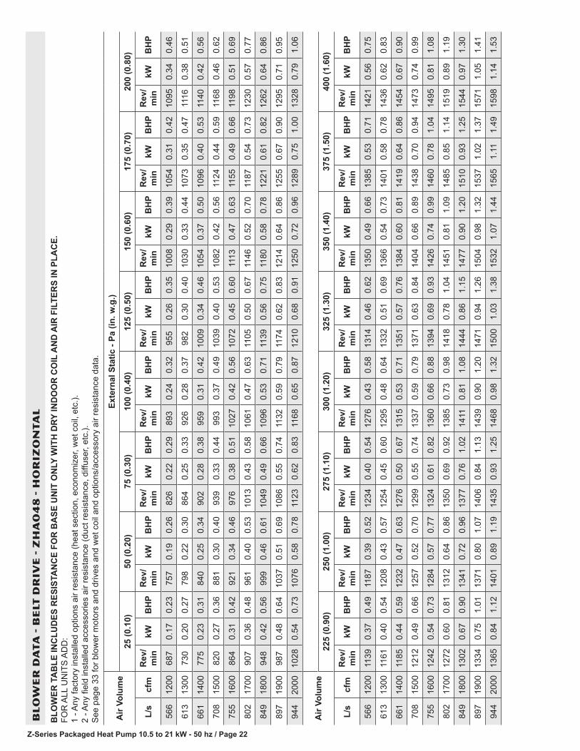
Z-Series Packaged Heat Pump 10.5 to 21 kW - 50 hz / Page 22
BL
OW
ER
DA
TA
- B
ELT
DR
IVE
- Z
HA
04
8 -
HO
RIZ
ON
TA
L
BLO
WER
TA
BLE
INC
LUD
ES R
ESIS
TAN
CE
FOR
BA
SE U
NIT
ON
LY W
ITH
DRY
IND
OO
R C
OIL
AN
D A
IR F
ILTE
RS
IN P
LAC
E.
FOR
ALL
UN
ITS
AD
D:
1 - A
ny fa
ctor
y in
stal
led
optio
ns a
ir re
sist
ance
(hea
t sec
tion,
eco
nom
izer
, wet
coi
l, et
c.).
2 - A
ny fi
eld
inst
alle
d ac
cess
orie
s ai
r res
ista
nce
(duc
t res
ista
nce,
diff
user
, etc
.).
See
pag
e 33
for b
low
er m
otor
s an
d dr
ives
and
wet
coi
l and
opt
ions
/acc
esso
ry a
ir re
sist
ance
dat
a.
Air
Volu
me
Exte
rnal
Sta
tic -
Pa (i
n. w
.g.)
25 (0
.10)
50 (0
.20)
75 (0
.30)
100
(0.4
0)12
5 (0
.50)
150
(0.6
0)17
5 (0
.70)
200
(0.8
0)
L/s
cfm
Rev
/m
inkW
BH
PR
ev/
min
kWB
HP
Rev
/m
inkW
BH
PR
ev/
min
kWB
HP
Rev
/m
inkW
BH
PR
ev/
min
kWB
HP
Rev
/m
inkW
BH
PR
ev/
min
kWB
HP
566
1200
687
0.17
0.23
757
0.19
0.26
826
0.22
0.29
893
0.24
0.32
955
0.26
0.35
1008
0.29
0.39
1054
0.31
0.42
1095
0.34
0.46
613
1300
730
0.20
0.27
798
0.22
0.30
864
0.25
0.33
926
0.28
0.37
982
0.30
0.40
1030
0.33
0.44
1073
0.35
0.47
1116
0.38
0.51
661
1400
775
0.23
0.31
840
0.25
0.34
902
0.28
0.38
959
0.31
0.42
1009
0.34
0.46
1054
0.37
0.50
1096
0.40
0.53
1140
0.42
0.56
708
1500
820
0.27
0.36
881
0.30
0.40
939
0.33
0.44
993
0.37
0.49
1039
0.40
0.53
1082
0.42
0.56
1124
0.44
0.59
1168
0.46
0.62
755
1600
864
0.31
0.42
921
0.34
0.46
976
0.38
0.51
1027
0.42
0.56
1072
0.45
0.60
1113
0.47
0.63
1155
0.49
0.66
1198
0.51
0.69
802
1700
907
0.36
0.48
961
0.40
0.53
1013
0.43
0.58
1061
0.47
0.63
1105
0.50
0.67
1146
0.52
0.70
1187
0.54
0.73
1230
0.57
0.77
849
1800
948
0.42
0.56
999
0.46
0.61
1049
0.49
0.66
1096
0.53
0.71
1139
0.56
0.75
1180
0.58
0.78
1221
0.61
0.82
1262
0.64
0.86
897
1900
987
0.48
0.64
1037
0.51
0.69
1086
0.55
0.74
1132
0.59
0.79
1174
0.62
0.83
1214
0.64
0.86
1255
0.67
0.90
1295
0.71
0.95
944
2000
1028
0.54
0.73
1076
0.58
0.78
1123
0.62
0.83
1168
0.65
0.87
1210
0.68
0.91
1250
0.72
0.96
1289
0.75
1.00
1328
0.79
1.06
Air
Volu
me
225
(0.9
0)25
0 (1
.00)
275
(1.1
0)30
0 (1
.20)
325
(1.3
0)35
0 (1
.40)
375
(1.5
0)40
0 (1
.60)
L/s
cfm
Rev
/m
inkW
BH
PR
ev/
min
kWB
HP
Rev
/m
inkW
BH
PR
ev/
min
kWB
HP
Rev
/m
inkW
BH
PR
ev/
min
kWB
HP
Rev
/m
inkW
BH
PR
ev/
min
kWB
HP
566
1200
1139
0.37
0.49
1187
0.39
0.52
1234
0.40
0.54
1276
0.43
0.58
1314
0.46
0.62
1350
0.49
0.66
1385
0.53
0.71
1421
0.56
0.75
613
1300
1161
0.40
0.54
1208
0.43
0.57
1254
0.45
0.60
1295
0.48
0.64
1332
0.51
0.69
1366
0.54
0.73
1401
0.58
0.78
1436
0.62
0.83
661
1400
1185
0.44
0.59
1232
0.47
0.63
1276
0.50
0.67
1315
0.53
0.71
1351
0.57
0.76
1384
0.60
0.81
1419
0.64
0.86
1454
0.67
0.90
708
1500
1212
0.49
0.66
1257
0.52
0.70
1299
0.55
0.74
1337
0.59
0.79
1371
0.63
0.84
1404
0.66
0.89
1438
0.70
0.94
1473
0.74
0.99
755
1600
1242
0.54
0.73
1284
0.57
0.77
1324
0.61
0.82
1360
0.66
0.88
1394
0.69
0.93
1426
0.74
0.99
1460
0.78
1.04
1495
0.81
1.08
802
1700
1272
0.60
0.81
1312
0.64
0.86
1350
0.69
0.92
1385
0.73
0.98
1418
0.78
1.04
1451
0.81
1.09
1485
0.85
1.14
1519
0.89
1.19
849
1800
1302
0.67
0.90
1341
0.72
0.96
1377
0.76
1.02
1411
0.81
1.08
1444
0.86
1.15
1477
0.90
1.20
1510
0.93
1.25
1544
0.97
1.30
897
1900
1334
0.75
1.01
1371
0.80
1.07
1406
0.84
1.13
1439
0.90
1.20
1471
0.94
1.26
1504
0.98
1.32
1537
1.02
1.37
1571
1.05
1.41
944
2000
1365
0.84
1.12
1401
0.89
1.19
1435
0.93
1.25
1468
0.98
1.32
1500
1.03
1.38
1532
1.07
1.44
1565
1.11
1.49
1598
1.14
1.53

Z-Series Packaged Heat Pump 10.5 to 21 kW - 50 hz / Page 23
BL
OW
ER
DA
TA
- B
ELT
DR
IVE
- Z
HA
06
0 -
DO
WN
FL
OW
BLO
WER
TA
BLE
INC
LUD
ES R
ESIS
TAN
CE
FOR
BA
SE U
NIT
ON
LY W
ITH
DRY
IND
OO
R C
OIL
AN
D A
IR F
ILTE
RS
IN P
LAC
E.
FOR
ALL
UN
ITS
AD
D:
1 - A
ny fa
ctor
y in
stal
led
optio
ns a
ir re
sist
ance
(hea
t sec
tion,
eco
nom
izer
, wet
coi
l, et
c.).
2 - A
ny fi
eld
inst
alle
d ac
cess
orie
s ai
r res
ista
nce
(duc
t res
ista
nce,
diff
user
, etc
.).
See
pag
e 33
for b
low
er m
otor
s an
d dr
ives
and
wet
coi
l and
opt
ions
/acc
esso
ry a
ir re
sist
ance
dat
a.
Air
Volu
me
Exte
rnal
Sta
tic -
Pa (i
n. w
.g.)
25 (0
.10)
50 (0
.20)
75 (0
.30)
100
(0.4
0)12
5 (0
.50)
150
(0.6
0)17
5 (0
.70)
200
(0.8
0)
L/s
cfm
Rev
/m
inkW
BH
PR
ev/
min
kWB
HP
Rev
/m
inkW
BH
PR
ev/
min
kWB
HP
Rev
/m
inkW
BH
PR
ev/
min
kWB
HP
Rev
/m
inkW
BH
PR
ev/
min
kWB
HP
755
1600
764
0.26
0.35
822
0.29
0.39
880
0.31
0.42
936
0.34
0.46
991
0.38
0.51
1042
0.41
0.55
1091
0.45
0.60
1136
0.48
0.64
802
1700
801
0.30
0.40
857
0.33
0.44
913
0.36
0.48
968
0.39
0.52
1020
0.43
0.57
1070
0.46
0.61
1117
0.49
0.66
1162
0.53
0.71
849
1800
838
0.34
0.46
893
0.37
0.50
947
0.40
0.54
1000
0.43
0.58
1051
0.47
0.63
1099
0.51
0.68
1145
0.54
0.73
1188
0.58
0.78
897
1900
876
0.39
0.52
929
0.42
0.56
982
0.46
0.61
1033
0.48
0.65
1082
0.52
0.70
1129
0.56
0.75
1173
0.60
0.80
1215
0.63
0.85
944
2000
914
0.44
0.59
966
0.47
0.63
1017
0.51
0.68
1067
0.54
0.72
1115
0.57
0.77
1160
0.62
0.83
1203
0.66
0.88
1244
0.70
0.94
991
2100
953
0.49
0.66
1004
0.53
0.71
1054
0.57
0.76
1102
0.60
0.81
1148
0.64
0.86
1192
0.69
0.92
1233
0.73
0.98
1273
0.78
1.04
1038
2200
993
0.55
0.74
1042
0.59
0.79
1090
0.63
0.85
1137
0.67
0.90
1181
0.72
0.96
1224
0.76
1.02
1264
0.81
1.09
1303
0.86
1.15
1085
2300
1033
0.62
0.83
1081
0.66
0.89
1128
0.70
0.94
1173
0.75
1.01
1216
0.80
1.07
1257
0.85
1.14
1296
0.90
1.20
1334
0.95
1.27
1133
2400
1074
0.69
0.93
1120
0.74
0.99
1166
0.78
1.05
1209
0.84
1.12
1251
0.89
1.19
1291
0.94
1.26
1329
0.99
1.33
1366
1.05
1.41
Air
Volu
me
225
(0.9
0)25
0 (1
.00)
275
(1.1
0)30
0 (1
.20)
325
(1.3
0)35
0 (1
.40)
375
(1.5
0)40
0 (1
.60)
L/s
cfm
Rev
/m
inkW
BH
PR
ev/
min
kWB
HP
Rev
/m
inkW
BH
PR
ev/
min
kWB
HP
Rev
/m
inkW
BH
PR
ev/
min
kWB
HP
Rev
/m
inkW
BH
PR
ev/
min
kWB
HP
755
1600
1180
0.51
0.68
1222
0.54
0.72
1263
0.57
0.76
1303
0.60
0.80
1341
0.63
0.85
1378
0.67
0.90
1414
0.70
0.94
1449
0.74
0.99
802
1700
1204
0.56
0.75
1245
0.59
0.79
1285
0.63
0.84
1325
0.66
0.88
1362
0.69
0.93
1398
0.73
0.98
1434
0.77
1.03
1468
0.81
1.08
849
1800
1229
0.62
0.83
1270
0.65
0.87
1309
0.69
0.92
1347
0.72
0.97
1384
0.76
1.02
1420
0.80
1.07
1454
0.84
1.12
1488
0.87
1.17
897
1900
1256
0.68
0.91
1296
0.72
0.96
1334
0.75
1.01
1371
0.80
1.07
1407
0.84
1.12
1442
0.87
1.17
1476
0.92
1.23
1509
0.95
1.28
944
2000
1284
0.75
1.00
1322
0.79
1.06
1360
0.83
1.11
1396
0.87
1.17
1431
0.92
1.23
1465
0.95
1.28
1498
0.99
1.33
1531
1.03
1.38
991
2100
1312
0.82
1.10
1350
0.87
1.16
1386
0.91
1.22
1422
0.95
1.28
1456
1.00
1.34
1489
1.04
1.40
1521
1.08
1.45
1554
1.12
1.50
1038
2200
1341
0.91
1.22
1378
0.95
1.28
1414
1.00
1.34
1448
1.05
1.41
1481
1.09
1.46
1513
1.13
1.52
1546
1.17
1.57
1578
1.21
1.62
1085
2300
1371
1.00
1.34
1407
1.05
1.41
1442
1.10
1.47
1475
1.15
1.54
1507
1.19
1.59
1539
1.23
1.65
1571
1.27
1.70
1602
1.31
1.75
1133
2400
1402
1.10
1.48
1436
1.16
1.55
1470
1.20
1.61
1503
1.25
1.67
1535
1.29
1.73
1566
1.34
1.79
1597
1.37
1.84
1628
1.41
1.89

Z-Series Packaged Heat Pump 10.5 to 21 kW - 50 hz / Page 24
BL
OW
ER
DA
TA
- B
ELT
DR
IVE
- Z
HA
06
0 -
HO
RIZ
ON
TA
L
BLO
WER
TA
BLE
INC
LUD
ES R
ESIS
TAN
CE
FOR
BA
SE U
NIT
ON
LY W
ITH
DRY
IND
OO
R C
OIL
AN
D A
IR F
ILTE
RS
IN P
LAC
E.
FOR
ALL
UN
ITS
AD
D:
1 - A
ny fa
ctor
y in
stal
led
optio
ns a
ir re
sist
ance
(hea
t sec
tion,
eco
nom
izer
, wet
coi
l, et
c.).
2 - A
ny fi
eld
inst
alle
d ac
cess
orie
s ai
r res
ista
nce
(duc
t res
ista
nce,
diff
user
, etc
.).
See
pag
e 33
for b
low
er m
otor
s an
d dr
ives
and
wet
coi
l and
opt
ions
/acc
esso
ry a
ir re
sist
ance
dat
a.
Air
Volu
me
Exte
rnal
Sta
tic -
Pa (i
n. w
.g.)
25 (0
.10)
50 (0
.20)
75 (0
.30)
100
(0.4
0)12
5 (0
.50)
150
(0.6
0)17
5 (0
.70)
200
(0.8
0)
L/s
cfm
Rev
/m
inkW
BH
PR
ev/
min
kWB
HP
Rev
/m
inkW
BH
PR
ev/
min
kWB
HP
Rev
/m
inkW
BH
PR
ev/
min
kWB
HP
Rev
/m
inkW
BH
PR
ev/
min
kWB
HP
755
1600
783
0.28
0.38
844
0.31
0.41
902
0.33
0.44
957
0.36
0.48
1008
0.39
0.52
1056
0.42
0.56
1100
0.45
0.6
1142
0.48
0.64
802
1700
825
0.33
0.44
882
0.35
0.47
938
0.37
0.5
989
0.40
0.54
1038
0.43
0.57
1083
0.46
0.62
1126
0.49
0.66
1166
0.53
0.71
849
1800
866
0.37
0.50
921
0.40
0.53
973
0.42
0.56
1021
0.45
0.6
1067
0.48
0.64
1111
0.51
0.68
1152
0.54
0.73
1191
0.58
0.78
897
1900
907
0.42
0.56
959
0.44
0.59
1008
0.47
0.63
1054
0.49
0.66
1098
0.53
0.71
1139
0.56
0.75
1179
0.60
0.8
1217
0.64
0.86
944
2000
948
0.47
0.63
996
0.49
0.66
1042
0.52
0.7
1086
0.55
0.74
1128
0.58
0.78
1168
0.62
0.83
1207
0.66
0.89
1244
0.70
0.94
991
2100
987
0.52
0.70
1033
0.55
0.74
1077
0.58
0.78
1119
0.61
0.82
1159
0.65
0.87
1198
0.69
0.93
1235
0.74
0.99
1272
0.78
1.05
1038
2200
1026
0.58
0.78
1070
0.61
0.82
1112
0.65
0.87
1152
0.69
0.92
1191
0.73
0.98
1228
0.77
1.03
1265
0.82
1.1
1301
0.87
1.16
1085
2300
1064
0.66
0.88
1106
0.69
0.92
1147
0.72
0.97
1186
0.77
1.03
1223
0.81
1.09
1260
0.86
1.15
1295
0.91
1.22
1331
0.95
1.28
1133
2400
1102
0.73
0.98
1143
0.77
1.03
1182
0.81
1.08
1220
0.86
1.15
1256
0.90
1.21
1292
0.95
1.28
1327
1.01
1.35
1362
1.06
1.42
Air
Volu
me
225
(0.9
0)25
0 (1
.00)
275
(1.1
0)30
0 (1
.20)
325
(1.3
0)35
0 (1
.40)
375
(1.5
0)40
0 (1
.60)
L/s
cfm
Rev
/m
inkW
BH
PR
ev/
min
kWB
HP
Rev
/m
inkW
BH
PR
ev/
min
kWB
HP
Rev
/m
inkW
BH
PR
ev/
min
kWB
HP
Rev
/m
inkW
BH
PR
ev/
min
kWB
HP
755
1600
1183
0.51
0.68
1223
0.54
0.72
1263
0.57
0.76
1302
0.60
0.81
1340
0.64
0.86
1377
0.68
0.91
1413
0.71
0.95
1448
0.75
1
802
1700
1205
0.56
0.75
1245
0.59
0.79
1284
0.63
0.84
1322
0.66
0.89
1360
0.70
0.94
1396
0.74
0.99
1431
0.78
1.04
1465
0.81
1.09
849
1800
1230
0.62
0.83
1268
0.65
0.87
1306
0.69
0.92
1344
0.73
0.98
1380
0.77
1.03
1416
0.81
1.08
1450
0.84
1.13
1483
0.89
1.19
897
1900
1255
0.68
0.91
1292
0.72
0.96
1330
0.76
1.02
1367
0.80
1.07
1402
0.84
1.13
1437
0.88
1.18
1470
0.93
1.24
1503
0.96
1.29
944
2000
1281
0.75
113
180.
791.
0613
550.
841.
1213
910.
881.
1814
250.
921.
2314
590.
961.
2914
921.
011.
3515
241.
041.
4
991
2100
1308
0.83
1.11
1345
0.87
1.17
1381
0.92
1.23
1416
0.96
1.29
1450
1.01
1.35
1482
1.05
1.41
1514
1.09
1.46
1546
1.13
1.52
1038
2200
1337
0.92
1.23
1372
0.96
1.29
1408
1.01
1.35
1442
1.06
1.42
1475
1.10
1.47
1507
1.14
1.53
1538
1.19
1.59
1569
1.22
1.64
1085
2300
1366
1.01
1.35
1401
1.06
1.42
1435
1.11
1.49
1469
1.16
1.55
1501
1.20
1.61
1532
1.25
1.67
1563
1.28
1.72
1594
1.32
1.77
1133
2400
1396
1.11
1.49
1431
1.16
1.56
1464
1.22
1.63
1496
1.26
1.69
1528
1.31
1.75
1559
1.35
1.81
1589
1.39
1.86
1619
1.42
1.91

Z-Series Packaged Heat Pump 10.5 to 21 kW - 50 hz / Page 25
BL
OW
ER
DA
TA
- B
ELT
DR
IVE
- Z
HB
03
6 -
DO
WN
FL
OW
BLO
WER
TA
BLE
INC
LUD
ES R
ESIS
TAN
CE
FOR
BA
SE U
NIT
ON
LY W
ITH
DRY
IND
OO
R C
OIL
AN
D A
IR F
ILTE
RS
IN P
LAC
E.
FOR
ALL
UN
ITS
AD
D:
1 - A
ny fa
ctor
y in
stal
led
optio
ns a
ir re
sist
ance
(hea
t sec
tion,
eco
nom
izer
, wet
coi
l, et
c.).
2 - A
ny fi
eld
inst
alle
d ac
cess
orie
s ai
r res
ista
nce
(duc
t res
ista
nce,
diff
user
, etc
.).
See
pag
e 33
for b
low
er m
otor
s an
d dr
ives
and
wet
coi
l and
opt
ions
/acc
esso
ry a
ir re
sist
ance
dat
a.
Air
Volu
me
Exte
rnal
Sta
tic -
Pa (i
n. w
.g.)
25 (0
.10)
50 (0
.20)
75 (0
.30)
100
(0.4
0)12
5 (0
.50)
150
(0.6
0)17
5 (0
.70)
200
(0.8
0)
L/s
cfm
Rev
/m
inkW
BH
PR
ev/
min
kWB
HP
Rev
/m
inkW
BH
PR
ev/
min
kWB
HP
Rev
/m
inkW
BH
PR
ev/
min
kWB
HP
Rev
/m
inkW
BH
PR
ev/
min
kWB
HP
425
900
562
0.08
0.11
621
0.10
0.13
685
0.12
0.16
752
0.13
0.18
818
0.16
0.21
883
0.18
0.24
944
0.20
0.27
1001
0.22
0.30
472
1000
584
0.10
0.13
644
0.12
0.16
707
0.13
0.18
773
0.16
0.21
838
0.18
0.24
901
0.20
0.27
960
0.22
0.30
1015
0.25
0.33
519
1100
609
0.12
0.16
669
0.13
0.18
732
0.16
0.21
796
0.18
0.24
860
0.20
0.27
921
0.22
0.30
978
0.25
0.34
1031
0.28
0.37
566
1200
635
0.14
0.19
696
0.16
0.21
758
0.18
0.24
821
0.20
0.27
883
0.23
0.31
942
0.25
0.34
997
0.28
0.38
1049
0.31
0.42
613
1300
664
0.16
0.22
725
0.19
0.25
786
0.21
0.28
848
0.23
0.31
908
0.26
0.35
965
0.29
0.39
1018
0.32
0.43
1068
0.35
0.47
661
1400
696
0.19
0.26
756
0.22
0.29
816
0.24
0.32
876
0.27
0.36
935
0.30
0.40
989
0.33
0.44
1041
0.36
0.48
1089
0.39
0.52
708
1500
729
0.22
0.30
788
0.25
0.33
848
0.28
0.37
906
0.31
0.41
962
0.34
0.45
1015
0.37
0.50
1065
0.40
0.54
1112
0.43
0.58
Air
Volu
me
Exte
rnal
Sta
tic -
Pa (i
n. w
.g.)
225
(0.9
0)25
0 (1
.00)
275
(1.1
0)30
0 (1
.20)
325
(1.3
0)35
0 (1
.40)
375
(1.5
0)40
0 (1
.60)
L/s
cfm
Rev
/m
inkW
BH
PR
ev/
min
kWB
HP
Rev
/m
inkW
BH
PR
ev/
min
kWB
HP
Rev
/m
inkW
BH
PR
ev/
min
kWB
HP
Rev
/m
inkW
BH
PR
ev/
min
kWB
HP
425
900
1053
0.24
0.32
1103
0.26
0.35
1149
0.28
0.38
1193
0.31
0.41
1234
0.32
0.43
1274
0.35
0.47
1312
0.37
0.50
1351
0.40
0.53
472
1000
1066
0.27
0.36
1114
0.29
0.39
1160
0.31
0.42
1204
0.34
0.45
1245
0.36
0.48
1284
0.38
0.51
1322
0.40
0.54
1361
0.43
0.58
519
1100
1081
0.30
0.40
1128
0.32
0.43
1173
0.34
0.46
1216
0.37
0.49
1257
0.40
0.53
1296
0.42
0.56
1334
0.45
0.60
1372
0.47
0.63
566
1200
1097
0.34
0.45
1144
0.36
0.48
1188
0.38
0.51
1231
0.40
0.54
1271
0.43
0.58
1310
0.46
0.62
1347
0.49
0.66
1385
0.51
0.69
613
1300
1115
0.37
0.50
1161
0.40
0.53
1204
0.42
0.56
1246
0.45
0.60
1286
0.48
0.64
1325
0.51
0.68
1362
0.54
0.72
1399
0.57
0.76
661
1400
1135
0.42
0.56
1179
0.44
0.59
1222
0.46
0.62
1264
0.49
0.66
1303
0.52
0.70
1341
0.56
0.75
1378
0.59
0.79
1415
0.62
0.83
708
1500
1157
0.46
0.62
1200
0.48
0.65
1242
0.51
0.69
1282
0.54
0.73
1321
0.57
0.77
1359
0.61
0.82
1396
0.64
0.86
1431
0.68
0.91

Z-Series Packaged Heat Pump 10.5 to 21 kW - 50 hz / Page 26
BL
OW
ER
DA
TA
- B
ELT
DR
IVE
- Z
HB
03
6 -
HO
RIZ
ON
TA
L
BLO
WER
TA
BLE
INC
LUD
ES R
ESIS
TAN
CE
FOR
BA
SE U
NIT
ON
LY W
ITH
DRY
IND
OO
R C
OIL
AN
D A
IR F
ILTE
RS
IN P
LAC
E.
FOR
ALL
UN
ITS
AD
D:
1 - A
ny fa
ctor
y in
stal
led
optio
ns a
ir re
sist
ance
(hea
t sec
tion,
eco
nom
izer
, wet
coi
l, et
c.).
2 - A
ny fi
eld
inst
alle
d ac
cess
orie
s ai
r res
ista
nce
(duc
t res
ista
nce,
diff
user
, etc
.).
See
pag
e 33
for b
low
er m
otor
s an
d dr
ives
and
wet
coi
l and
opt
ions
/acc
esso
ry a
ir re
sist
ance
dat
a.
Air
Volu
me
Exte
rnal
Sta
tic -
Pa (i
n. w
.g.)
25 (0
.10)
50 (0
.20)
75 (0
.30)
100
(0.4
0)12
5 (0
.50)
150
(0.6
0)17
5 (0
.70)
200
(0.8
0)
L/s
cfm
Rev
/m
inkW
BH
PR
ev/
min
kWB
HP
Rev
/m
inkW
BH
PR
ev/
min
kWB
HP
Rev
/m
inkW
BH
PR
ev/
min
kWB
HP
Rev
/m
inkW
BH
PR
ev/
min
kWB
HP
425
900
560
0.12
0.16
624
0.13
0.18
692
0.15
0.20
761
0.16
0.21
830
0.17
0.23
896
0.19
0.25
956
0.20
0.27
1012
0.22
0.29
472
1000
583
0.13
0.18
647
0.15
0.20
715
0.16
0.22
783
0.18
0.24
850
0.19
0.25
914
0.20
0.27
972
0.22
0.30
1025
0.25
0.33
519
1100
609
0.15
0.20
673
0.16
0.22
740
0.18
0.24
808
0.19
0.26
873
0.21
0.28
934
0.23
0.31
990
0.25
0.34
1041
0.28
0.37
566
1200
637
0.17
0.23
702
0.19
0.25
769
0.20
0.27
835
0.22
0.29
898
0.24
0.32
956
0.26
0.35
1009
0.28
0.38
1058
0.31
0.41
613
1300
669
0.19
0.26
734
0.21
0.28
800
0.22
0.30
863
0.25
0.33
924
0.27
0.36
979
0.29
0.39
1030
0.32
0.43
1077
0.34
0.46
661
1400
704
0.22
0.29
768
0.24
0.32
832
0.26
0.35
894
0.28
0.37
951
0.31
0.41
1004
0.33
0.44
1052
0.36
0.48
1097
0.39
0.52
708
1500
742
0.25
0.33
805
0.27
0.36
867
0.29
0.39
925
0.31
0.42
980
0.34
0.46
1030
0.37
0.50
1076
0.40
0.54
1119
0.43
0.58
Air
Volu
me
225
(0.9
0)25
0 (1
.00)
275
(1.1
0)30
0 (1
.20)
325
(1.3
0)35
0 (1
.40)
375
(1.5
0)40
0 (1
.60)
L/s
cfm
Rev
/m
inkW
BH
PR
ev/
min
kWB
HP
Rev
/m
inkW
BH
PR
ev/
min
kWB
HP
Rev
/m
inkW
BH
PR
ev/
min
kWB
HP
Rev
/m
inkW
BH
PR
ev/
min
kWB
HP
425
900
1064
0.24
0.32
1114
0.26
0.35
1162
0.28
0.38
1208
0.31
0.41
1251
0.34
0.45
1293
0.37
0.49
1333
0.39
0.52
1373
0.42
0.56
472
1000
1076
0.27
0.36
1124
0.29
0.39
1170
0.31
0.42
1216
0.34
0.46
1259
0.37
0.49
1300
0.40
0.53
1340
0.43
0.57
1379
0.46
0.61
519
1100
1089
0.30
0.40
1136
0.32
0.43
1181
0.34
0.46
1225
0.37
0.50
1268
0.40
0.54
1308
0.43
0.58
1347
0.46
0.62
1386
0.49
0.66
566
1200
1104
0.34
0.45
1150
0.36
0.48
1194
0.38
0.51
1237
0.41
0.55
1279
0.44
0.59
1319
0.47
0.63
1357
0.50
0.67
1394
0.53
0.71
613
1300
1121
0.37
0.50
1165
0.40
0.53
1209
0.43
0.57
1251
0.46
0.61
1292
0.48
0.65
1331
0.51
0.69
1368
0.54
0.73
1405
0.58
0.78
661
1400
1140
0.42
0.56
1183
0.44
0.59
1225
0.47
0.63
1266
0.50
0.67
1306
0.53
0.71
1345
0.57
0.76
1382
0.60
0.80
1417
0.63
0.85
708
1500
1161
0.46
0.62
1202
0.48
0.65
1243
0.51
0.69
1284
0.54
0.73
1323
0.58
0.78
1360
0.62
0.83
1396
0.65
0.87
1432
0.69
0.92

Z-Series Packaged Heat Pump 10.5 to 21 kW - 50 hz / Page 27
BL
OW
ER
DA
TA
- B
ELT
DR
IVE
- Z
HB
04
8 -
DO
WN
FL
OW
BLO
WER
TA
BLE
INC
LUD
ES R
ESIS
TAN
CE
FOR
BA
SE U
NIT
ON
LY W
ITH
DRY
IND
OO
R C
OIL
AN
D A
IR F
ILTE
RS
IN P
LAC
E.
FOR
ALL
UN
ITS
AD
D:
1 - A
ny fa
ctor
y in
stal
led
optio
ns a
ir re
sist
ance
(hea
t sec
tion,
eco
nom
izer
, wet
coi
l, et
c.).
2 - A
ny fi
eld
inst
alle
d ac
cess
orie
s ai
r res
ista
nce
(duc
t res
ista
nce,
diff
user
, etc
.).
See
pag
e 33
for b
low
er m
otor
s an
d dr
ives
and
wet
coi
l and
opt
ions
/acc
esso
ry a
ir re
sist
ance
dat
a.
Air
Volu
me
Exte
rnal
Sta
tic -
Pa (i
n. w
.g.)
25 (0
.10)
50 (0
.20)
75 (0
.30)
100
(0.4
0)12
5 (0
.50)
150
(0.6
0)17
5 (0
.70)
200
(0.8
0)
L/s
cfm
Rev
/m
inkW
BH
PR
ev/
min
kWB
HP
Rev
/m
inkW
BH
PR
ev/
min
kWB
HP
Rev
/m
inkW
BH
PR
ev/
min
kWB
HP
Rev
/m
inkW
BH
PR
ev/
min
kWB
HP
566
1200
620
0.17
0.23
681
0.22
0.29
744
0.25
0.34
809
0.29
0.39
875
0.32
0.43
941
0.35
0.47
1004
0.38
0.51
1060
0.40
0.54
613
1300
652
0.21
0.28
713
0.25
0.34
775
0.29
0.39
839
0.33
0.44
903
0.36
0.48
967
0.38
0.51
1025
0.41
0.55
1078
0.44
0.59
661
1400
687
0.25
0.33
747
0.29
0.39
809
0.33
0.44
871
0.37
0.49
934
0.40
0.53
994
0.43
0.57
1048
0.46
0.61
1098
0.48
0.64
708
1500
724
0.30
0.40
784
0.34
0.45
844
0.37
0.50
905
0.40
0.54
965
0.44
0.59
1021
0.46
0.62
1071
0.49
0.66
1118
0.52
0.70
755
1600
764
0.34
0.46
823
0.38
0.51
882
0.42
0.56
940
0.45
0.60
997
0.48
0.65
1048
0.51
0.69
1094
0.54
0.72
1140
0.56
0.75
802
1700
806
0.40
0.53
863
0.43
0.58
919
0.46
0.62
975
0.50
0.67
1028
0.53
0.71
1075
0.56
0.75
1119
0.58
0.78
1164
0.60
0.81
849
1800
849
0.45
0.60
903
0.48
0.65
957
0.51
0.69
1010
0.55
0.74
1058
0.58
0.78
1102
0.61
0.82
1145
0.63
0.85
1189
0.66
0.88
897
1900
892
0.51
0.68
944
0.54
0.72
995
0.57
0.77
1045
0.61
0.82
1089
0.64
0.86
1131
0.66
0.89
1174
0.69
0.92
1217
0.71
0.95
944
2000
935
0.57
0.76
984
0.60
0.81
1033
0.64
0.86
1079
0.68
0.91
1122
0.71
0.95
1163
0.72
0.97
1204
0.75
1.00
1247
0.77
1.03
Air
Volu
me
Exte
rnal
Sta
tic -
Pa (i
n. w
.g.)
225
(0.9
0)25
0 (1
.00)
275
(1.1
0)30
0 (1
.20)
325
(1.3
0)35
0 (1
.40)
375
(1.5
0)40
0 (1
.60)
L/s
cfm
Rev
/m
inkW
BH
PR
ev/
min
kWB
HP
Rev
/m
inkW
BH
PR
ev/
min
kWB
HP
Rev
/m
inkW
BH
PR
ev/
min
kWB
HP
Rev
/m
inkW
BH
PR
ev/
min
kWB
HP
566
1200
1111
0.43
0.58
1156
0.45
0.60
1199
0.46
0.62
1241
0.47
0.63
1284
0.48
0.65
1326
0.50
0.67
1367
0.53
0.71
1408
0.55
0.74
613
1300
1127
0.46
0.62
1172
0.48
0.65
1214
0.49
0.66
1256
0.51
0.68
1299
0.52
0.70
1341
0.54
0.73
1381
0.57
0.77
1421
0.60
0.81
661
1400
1145
0.51
0.68
1189
0.52
0.70
1231
0.54
0.72
1274
0.55
0.74
1316
0.57
0.76
1357
0.59
0.79
1397
0.62
0.83
1436
0.66
0.88
708
1500
1164
0.54
0.73
1208
0.56
0.75
1251
0.58
0.78
1293
0.60
0.80
1334
0.62
0.83
1374
0.64
0.86
1413
0.68
0.91
1451
0.71
0.95
755
1600
1185
0.59
0.79
1229
0.60
0.81
1271
0.63
0.84
1313
0.64
0.86
1354
0.67
0.90
1393
0.70
0.94
1431
0.73
0.98
1468
0.77
1.03
802
1700
1208
0.63
0.84
1252
0.65
0.87
1294
0.67
0.90
1335
0.70
0.94
1375
0.73
0.98
1413
0.76
1.02
1449
0.80
1.07
1485
0.84
1.12
849
1800
1233
0.68
0.91
1276
0.70
0.94
1318
0.73
0.98
1358
0.76
1.02
1397
0.79
1.06
1434
0.83
1.11
1469
0.87
1.16
1504
0.90
1.21
897
1900
1261
0.73
0.98
1303
0.76
1.02
1343
0.79
1.06
1382
0.83
1.11
1420
0.87
1.16
1455
0.90
1.21
1490
0.94
1.26
1525
0.98
1.31
944
2000
1289
0.80
1.07
1330
0.83
1.11
1370
0.87
1.16
1407
0.90
1.21
1444
0.95
1.27
1478
0.98
1.32
1513
1.02
1.37
1547
1.06
1.42

Z-Series Packaged Heat Pump 10.5 to 21 kW - 50 hz / Page 28
BL
OW
ER
DA
TA
- B
ELT
DR
IVE
- Z
HB
04
8 -
HO
RIZ
ON
TA
L
BLO
WER
TA
BLE
INC
LUD
ES R
ESIS
TAN
CE
FOR
BA
SE U
NIT
ON
LY W
ITH
DRY
IND
OO
R C
OIL
AN
D A
IR F
ILTE
RS
IN P
LAC
E.
FOR
ALL
UN
ITS
AD
D:
1 - A
ny fa
ctor
y in
stal
led
optio
ns a
ir re
sist
ance
(hea
t sec
tion,
eco
nom
izer
, wet
coi
l, et
c.).
2 - A
ny fi
eld
inst
alle
d ac
cess
orie
s ai
r res
ista
nce
(duc
t res
ista
nce,
diff
user
, etc
.).
See
pag
e 33
for b
low
er m
otor
s an
d dr
ives
and
wet
coi
l and
opt
ions
/acc
esso
ry a
ir re
sist
ance
dat
a.
Air
Volu
me
Exte
rnal
Sta
tic -
Pa (i
n. w
.g.)
25 (0
.10)
50 (0
.20)
75 (0
.30)
100
(0.4
0)12
5 (0
.50)
150
(0.6
0)17
5 (0
.70)
200
(0.8
0)
L/s
cfm
Rev
/m
inkW
BH
PR
ev/
min
kWB
HP
Rev
/m
inkW
BH
PR
ev/
min
kWB
HP
Rev
/m
inkW
BH
PR
ev/
min
kWB
HP
Rev
/m
inkW
BH
PR
ev/
min
kWB
HP
566
1200
614
0.16
0.21
681
0.19
0.25
752
0.22
0.30
821
0.25
0.34
888
0.29
0.39
950
0.32
0.43
1006
0.34
0.46
1057
0.37
0.49
613
1300
644
0.18
0.24
712
0.22
0.29
782
0.25
0.34
850
0.29
0.39
915
0.32
0.43
974
0.35
0.47
1027
0.38
0.51
1076
0.40
0.53
661
1400
677
0.22
0.29
746
0.25
0.34
814
0.29
0.39
880
0.33
0.44
942
0.36
0.48
998
0.39
0.52
1049
0.41
0.55
1097
0.43
0.58
708
1500
714
0.25
0.34
781
0.30
0.40
848
0.34
0.45
911
0.37
0.49
970
0.40
0.53
1023
0.43
0.57
1072
0.45
0.60
1119
0.47
0.63
755
1600
752
0.30
0.40
818
0.34
0.45
882
0.37
0.50
943
0.41
0.55
999
0.44
0.59
1050
0.46
0.62
1097
0.49
0.66
1142
0.51
0.69
802
1700
792
0.34
0.46
855
0.39
0.52
917
0.42
0.56
975
0.46
0.61
1028
0.48
0.64
1077
0.51
0.68
1123
0.54
0.72
1166
0.56
0.75
849
1800
832
0.40
0.53
894
0.43
0.58
952
0.47
0.63
1007
0.50
0.67
1058
0.52
0.70
1105
0.55
0.74
1149
0.58
0.78
1192
0.61
0.82
897
1900
873
0.45
0.60
932
0.48
0.65
988
0.51
0.69
1040
0.54
0.73
1088
0.57
0.77
1134
0.60
0.81
1177
0.63
0.85
1219
0.67
0.90
944
2000
914
0.50
0.67
970
0.54
0.72
1023
0.57
0.76
1073
0.60
0.80
1120
0.63
0.85
1163
0.66
0.89
1205
0.70
0.94
1246
0.74
0.99
Air
Volu
me
225
(0.9
0)25
0 (1
.00)
275
(1.1
0)30
0 (1
.20)
325
(1.3
0)35
0 (1
.40)
375
(1.5
0)40
0 (1
.60)
L/s
cfm
Rev
/m
inkW
BH
PR
ev/
min
kWB
HP
Rev
/m
inkW
BH
PR
ev/
min
kWB
HP
Rev
/m
inkW
BH
PR
ev/
min
kWB
HP
Rev
/m
inkW
BH
PR
ev/
min
kWB
HP
566
1200
1105
0.38
0.51
1152
0.40
0.53
1197
0.41
0.55
1240
0.43
0.58
1280
0.46
0.61
1320
0.48
0.64
1358
0.51
0.68
1395
0.54
0.72
613
1300
1123
0.41
0.55
1169
0.43
0.57
1213
0.45
0.60
1255
0.47
0.63
1295
0.50
0.67
1334
0.52
0.70
1372
0.55
0.74
1409
0.59
0.79
661
1400
1142
0.45
0.60
1187
0.47
0.63
1230
0.49
0.66
1272
0.51
0.69
1312
0.54
0.73
1350
0.57
0.77
1388
0.61
0.82
1424
0.64
0.86
708
1500
1163
0.49
0.66
1207
0.51
0.69
1249
0.54
0.72
1290
0.57
0.76
1330
0.60
0.80
1368
0.63
0.85
1405
0.67
0.90
1441
0.70
0.94
755
1600
1185
0.54
0.72
1228
0.56
0.75
1270
0.59
0.79
1310
0.62
0.83
1349
0.66
0.88
1387
0.69
0.93
1423
0.73
0.98
1459
0.77
1.03
802
1700
1209
0.58
0.78
1251
0.61
0.82
1292
0.65
0.87
1331
0.69
0.92
1370
0.72
0.97
1407
0.76
1.02
1443
0.80
1.07
1478
0.84
1.12
849
1800
1234
0.64
0.86
1275
0.68
0.91
1315
0.72
0.96
1354
0.75
1.01
1391
0.79
1.06
1428
0.83
1.11
1463
0.87
1.17
1498
0.91
1.22
897
1900
1260
0.71
0.95
1300
0.75
1.00
1340
0.78
1.05
1377
0.83
1.11
1414
0.87
1.16
1450
0.91
1.22
1485
0.95
1.27
1519
0.98
1.32
944
2000
1287
0.78
1.04
1326
0.82
1.10
1365
0.87
1.16
1402
0.90
1.21
1437
0.95
1.27
1472
0.99
1.33
1507
1.03
1.38
1541
1.07
1.43
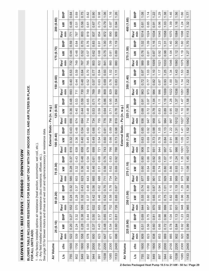
Z-Series Packaged Heat Pump 10.5 to 21 kW - 50 hz / Page 29
BL
OW
ER
DA
TA
- B
ELT
DR
IVE
- Z
HB
06
0 -
DO
WN
FL
OW
BLO
WER
TA
BLE
INC
LUD
ES R
ESIS
TAN
CE
FOR
BA
SE U
NIT
ON
LY W
ITH
DRY
IND
OO
R C
OIL
AN
D A
IR F
ILTE
RS
IN P
LAC
E.
FOR
ALL
UN
ITS
AD
D:
1 - A
ny fa
ctor
y in
stal
led
optio
ns a
ir re
sist
ance
(hea
t sec
tion,
eco
nom
izer
, wet
coi
l, et
c.).
2 - A
ny fi
eld
inst
alle
d ac
cess
orie
s ai
r res
ista
nce
(duc
t res
ista
nce,
diff
user
, etc
.).
See
pag
e 33
for b
low
er m
otor
s an
d dr
ives
and
wet
coi
l and
opt
ions
/acc
esso
ry a
ir re
sist
ance
dat
a.
Air
Volu
me
Exte
rnal
Sta
tic -
Pa (i
n. w
.g.)
25 (0
.10)
50 (0
.20)
75 (0
.30)
100
(0.4
0)12
5 (0
.50)
150
(0.6
0)17
5 (0
.70)
200
(0.8
0)
L/s
cfm
Rev
/m
inkW
BH
PR
ev/
min
kWB
HP
Rev
/m
inkW
BH
PR
ev/
min
kWB
HP
Rev
/m
inkW
BH
PR
ev/
min
kWB
HP
Rev
/m
inkW
BH
PR
ev/
min
kWB
HP
755
1600
522
0.20
0.27
552
0.24
0.32
585
0.28
0.37
619
0.32
0.43
656
0.36
0.48
693
0.40
0.53
732
0.44
0.59
771
0.48
0.64
802
1700
539
0.24
0.32
570
0.28
0.37
603
0.32
0.43
638
0.36
0.48
674
0.40
0.53
711
0.44
0.59
749
0.48
0.64
787
0.51
0.69
849
1800
558
0.28
0.38
589
0.32
0.43
623
0.36
0.48
658
0.40
0.54
694
0.44
0.59
730
0.48
0.64
767
0.52
0.70
803
0.56
0.75
897
1900
578
0.33
0.44
610
0.37
0.49
643
0.40
0.54
678
0.45
0.60
714
0.48
0.65
749
0.52
0.70
785
0.57
0.76
819
0.61
0.82
944
2000
600
0.37
0.50
632
0.42
0.56
665
0.46
0.61
699
0.49
0.66
734
0.53
0.71
769
0.57
0.77
803
0.62
0.83
837
0.67
0.90
991
2100
623
0.43
0.57
655
0.46
0.62
688
0.51
0.68
721
0.54
0.73
755
0.59
0.79
789
0.63
0.84
822
0.68
0.91
854
0.73
0.98
1038
2200
647
0.48
0.65
678
0.52
0.70
711
0.56
0.75
743
0.60
0.81
776
0.64
0.86
809
0.69
0.93
841
0.75
1.00
872
0.79
1.06
1085
2300
671
0.54
0.73
702
0.58
0.78
734
0.62
0.83
766
0.66
0.89
798
0.71
0.95
829
0.76
1.02
860
0.81
1.09
890
0.87
1.16
1133
2400
696
0.60
0.81
726
0.65
0.87
757
0.69
0.92
788
0.73
0.98
819
0.78
1.04
850
0.83
1.11
880
0.89
1.19
909
0.94
1.26
Air
Volu
me
Exte
rnal
Sta
tic -
Pa (i
n. w
.g.)
225
(0.9
0)25
0 (1
.00)
275
(1.1
0)30
0 (1
.20)
325
(1.3
0)35
0 (1
.40)
375
(1.5
0)40
0 (1
.60)
L/s
cfm
Rev
/m
inkW
BH
PR
ev/
min
kWB
HP
Rev
/m
inkW
BH
PR
ev/
min
kWB
HP
Rev
/m
inkW
BH
PR
ev/
min
kWB
HP
Rev
/m
inkW
BH
PR
ev/
min
kWB
HP
755
1600
809
0.51
0.69
844
0.55
0.74
877
0.60
0.80
908
0.63
0.85
936
0.68
0.91
963
0.72
0.97
989
0.76
1.02
1014
0.81
1.08
802
1700
823
0.56
0.75
857
0.60
0.80
889
0.64
0.86
919
0.69
0.92
947
0.72
0.97
973
0.77
1.03
999
0.81
1.09
1024
0.85
1.14
849
1800
838
0.60
0.81
870
0.65
0.87
901
0.69
0.92
931
0.73
0.98
958
0.78
1.04
984
0.82
1.10
1009
0.87
1.16
1034
0.91
1.22
897
1900
853
0.66
0.88
885
0.70
0.94
915
0.74
0.99
944
0.78
1.05
971
0.83
1.11
996
0.87
1.17
1021
0.92
1.23
1045
0.96
1.29
944
2000
869
0.72
0.96
899
0.75
1.01
929
0.80
1.07
957
0.84
1.13
984
0.89
1.19
1009
0.93
1.25
1033
0.98
1.31
1058
1.03
1.38
991
2100
885
0.78
1.04
915
0.82
1.10
944
0.86
1.15
971
0.91
1.22
997
0.95
1.28
1022
1.00
1.34
1046
1.04
1.40
1070
1.09
1.46
1038
2200
902
0.84
1.13
931
0.89
1.19
959
0.93
1.24
986
0.98
1.31
1012
1.02
1.37
1036
1.07
1.43
1060
1.12
1.50
1084
1.16
1.56
1085
2300
920
0.92
1.23
948
0.96
1.29
975
1.01
1.35
1001
1.05
1.41
1027
1.10
1.47
1051
1.14
1.53
1075
1.19
1.60
1098
1.24
1.66
1133
2400
938
0.99
1.33
965
1.04
1.39
992
1.08
1.45
1017
1.13
1.52
1042
1.18
1.58
1066
1.22
1.64
1090
1.27
1.70
1113
1.32
1.77

Z-Series Packaged Heat Pump 10.5 to 21 kW - 50 hz / Page 30
BL
OW
ER
DA
TA
- B
ELT
DR
IVE
- Z
HB
06
0 -
HO
RIZ
ON
TA
L
BLO
WER
TA
BLE
INC
LUD
ES R
ESIS
TAN
CE
FOR
BA
SE U
NIT
ON
LY W
ITH
DRY
IND
OO
R C
OIL
AN
D A
IR F
ILTE
RS
IN P
LAC
E.
FOR
ALL
UN
ITS
AD
D:
1 - A
ny fa
ctor
y in
stal
led
optio
ns a
ir re
sist
ance
(hea
t sec
tion,
eco
nom
izer
, wet
coi
l, et
c.).
2 - A
ny fi
eld
inst
alle
d ac
cess
orie
s ai
r res
ista
nce
(duc
t res
ista
nce,
diff
user
, etc
.).
See
pag
e 33
for b
low
er m
otor
s an
d dr
ives
and
wet
coi
l and
opt
ions
/acc
esso
ry a
ir re
sist
ance
dat
a.
Air
Volu
me
Exte
rnal
Sta
tic -
Pa (i
n. w
.g.)
25 (0
.10)
50 (0
.20)
75 (0
.30)
100
(0.4
0)12
5 (0
.50)
150
(0.6
0)17
5 (0
.70)
200
(0.8
0)
L/s
cfm
Rev
/m
inkW
BH
PR
ev/
min
kWB
HP
Rev
/m
inkW
BH
PR
ev/
min
kWB
HP
Rev
/m
inkW
BH
PR
ev/
min
kWB
HP
Rev
/m
inkW
BH
PR
ev/
min
kWB
HP
755
1600
525
0.22
0.30
561
0.25
0.34
597
0.29
0.39
635
0.32
0.43
673
0.35
0.47
711
0.38
0.51
748
0.42
0.56
784
0.46
0.61
802
1700
543
0.25
0.34
578
0.29
0.39
615
0.32
0.43
653
0.36
0.48
691
0.39
0.52
728
0.43
0.57
765
0.46
0.62
800
0.50
0.67
849
1800
561
0.29
0.39
597
0.33
0.44
635
0.37
0.49
672
0.40
0.53
710
0.43
0.58
746
0.47
0.63
782
0.51
0.68
816
0.54
0.73
897
1900
581
0.33
0.44
618
0.37
0.49
655
0.40
0.54
692
0.44
0.59
729
0.48
0.64
765
0.51
0.69
800
0.56
0.75
833
0.60
0.80
944
2000
602
0.37
0.50
639
0.41
0.55
676
0.46
0.61
713
0.49
0.66
749
0.53
0.71
784
0.57
0.76
818
0.61
0.82
850
0.66
0.88
991
2100
625
0.43
0.57
661
0.46
0.62
698
0.50
0.67
735
0.54
0.73
770
0.58
0.78
804
0.63
0.84
837
0.67
0.90
868
0.72
0.96
1038
2200
648
0.48
0.64
685
0.51
0.69
721
0.56
0.75
757
0.60
0.80
791
0.64
0.86
824
0.69
0.92
856
0.73
0.98
886
0.78
1.05
1085
2300
673
0.53
0.71
709
0.57
0.77
745
0.62
0.83
780
0.66
0.88
813
0.70
0.94
845
0.75
1.01
876
0.81
1.08
905
0.86
1.15
1133
2400
699
0.59
0.79
734
0.63
0.85
769
0.68
0.91
803
0.72
0.97
835
0.78
1.04
866
0.83
1.11
896
0.88
1.18
924
0.93
1.25
Air
Volu
me
225
(0.9
0)25
0 (1
.00)
275
(1.1
0)30
0 (1
.20)
325
(1.3
0)35
0 (1
.40)
375
(1.5
0)40
0 (1
.60)
L/s
cfm
Rev
/m
inkW
BH
PR
ev/
min
kWB
HP
Rev
/m
inkW
BH
PR
ev/
min
kWB
HP
Rev
/m
inkW
BH
PR
ev/
min
kWB
HP
Rev
/m
inkW
BH
PR
ev/
min
kWB
HP
755
1600
819
0.49
0.66
851
0.54
0.72
883
0.57
0.77
913
0.62
0.83
943
0.66
0.89
971
0.71
0.95
998
0.75
1.01
1024
0.80
1.07
802
1700
833
0.54
0.72
865
0.58
0.78
896
0.63
0.84
926
0.67
0.90
954
0.72
0.96
982
0.76
1.02
1009
0.81
1.08
1034
0.85
1.14
849
1800
848
0.59
0.79
880
0.63
0.85
910
0.69
0.92
939
0.73
0.98
967
0.78
1.04
994
0.82
1.10
1020
0.87
1.16
1045
0.92
1.23
897
1900
864
0.65
0.87
895
0.69
0.93
924
0.74
0.99
953
0.79
1.06
980
0.84
1.12
1007
0.88
1.18
1032
0.93
1.25
1056
0.98
1.31
944
2000
881
0.71
0.95
911
0.75
1.01
940
0.81
1.08
967
0.85
1.14
994
0.90
1.21
1020
0.95
1.27
1044
1.00
1.34
1068
1.04
1.40
991
2100
898
0.77
1.03
927
0.82
1.10
955
0.87
1.17
982
0.92
1.23
1008
0.97
1.30
1033
1.02
1.37
1057
1.07
1.43
1080
1.12
1.50
1038
2200
916
0.84
1.12
944
0.89
1.19
971
0.94
1.26
998
0.99
1.33
1023
1.04
1.40
1047
1.10
1.47
1071
1.15
1.54
1093
1.19
1.60
1085
2300
934
0.91
1.22
961
0.96
1.29
988
1.01
1.36
1014
1.07
1.43
1038
1.12
1.50
1062
1.18
1.58
1085
1.23
1.65
1107
1.28
1.71
1133
2400
952
0.98
1.32
979
1.04
1.40
1005
1.10
1.47
1030
1.15
1.54
1054
1.21
1.62
1077
1.26
1.69
1099
1.31
1.76
1121
1.37
1.83
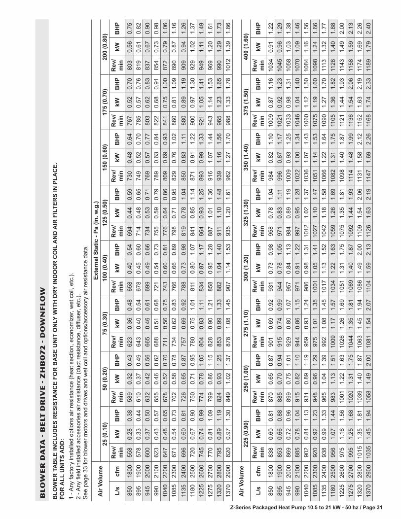
Z-Series Packaged Heat Pump 10.5 to 21 kW - 50 hz / Page 31
BL
OW
ER
DA
TA
- B
ELT
DR
IVE
- Z
HB
07
2 -
DO
WN
FL
OW
BLO
WER
TA
BLE
INC
LUD
ES R
ESIS
TAN
CE
FOR
BA
SE U
NIT
ON
LY W
ITH
DRY
IND
OO
R C
OIL
AN
D A
IR F
ILTE
RS
IN P
LAC
E.
FOR
ALL
UN
ITS
AD
D:
1 - A
ny fa
ctor
y in
stal
led
optio
ns a
ir re
sist
ance
(hea
t sec
tion,
eco
nom
izer
, wet
coi
l, et
c.).
2 - A
ny fi
eld
inst
alle
d ac
cess
orie
s ai
r res
ista
nce
(duc
t res
ista
nce,
diff
user
, etc
.).
See
pag
e 33
for b
low
er m
otor
s an
d dr
ives
and
wet
coi
l and
opt
ions
/acc
esso
ry a
ir re
sist
ance
dat
a.
Air
Volu
me
Exte
rnal
Sta
tic -
Pa (i
n. w
.g.)
25 (0
.10)
50 (0
.20)
75 (0
.30)
100
(0.4
0)12
5 (0
.50)
150
(0.6
0)17
5 (0
.70)
200
(0.8
0)
L/s
cfm
Rev
/m
inkW
BH
PR
ev/
min
kWB
HP
Rev
/m
inkW
BH
PR
ev/
min
kWB
HP
Rev
/m
inkW
BH
PR
ev/
min
kWB
HP
Rev
/m
inkW
BH
PR
ev/
min
kWB
HP
850
1800
558
0.28
0.38
589
0.32
0.43
623
0.36
0.48
658
0.40
0.54
694
0.44
0.59
730
0.48
0.64
767
0.52
0.70
803
0.56
0.75
895
1900
578
0.33
0.44
610
0.37
0.49
643
0.40
0.54
678
0.45
0.60
714
0.48
0.65
749
0.52
0.70
785
0.57
0.76
819
0.61
0.82
945
2000
600
0.37
0.50
632
0.42
0.56
665
0.46
0.61
699
0.49
0.66
734
0.53
0.71
769
0.57
0.77
803
0.62
0.83
837
0.67
0.90
990
2100
623
0.43
0.57
655
0.46
0.62
688
0.51
0.68
721
0.54
0.73
755
0.59
0.79
789
0.63
0.84
822
0.68
0.91
854
0.73
0.98
1040
2200
647
0.48
0.65
678
0.52
0.70
711
0.56
0.75
743
0.60
0.81
776
0.64
0.86
809
0.69
0.93
841
0.75
1.00
872
0.79
1.06
1085
2300
671
0.54
0.73
702
0.58
0.78
734
0.62
0.83
766
0.66
0.89
798
0.71
0.95
829
0.76
1.02
860
0.81
1.09
890
0.87
1.16
1135
2400
696
0.60
0.81
726
0.65
0.87
757
0.69
0.92
788
0.73
0.98
819
0.78
1.04
850
0.83
1.11
880
0.89
1.19
909
0.94
1.26
1180
2500
720
0.67
0.90
750
0.71
0.95
780
0.75
1.01
811
0.80
1.07
841
0.85
1.14
871
0.91
1.22
900
0.97
1.30
929
1.02
1.37
1225
2600
745
0.74
0.99
774
0.78
1.05
804
0.83
1.11
834
0.87
1.17
864
0.93
1.25
893
0.99
1.33
921
1.05
1.41
949
1.11
1.49
1275
2700
770
0.81
1.09
799
0.86
1.15
828
0.90
1.21
858
0.95
1.28
887
1.01
1.36
916
1.07
1.44
943
1.14
1.53
969
1.20
1.61
1320
2800
795
0.89
1.19
824
0.93
1.25
853
0.99
1.33
882
1.04
1.40
911
1.10
1.48
939
1.16
1.56
965
1.23
1.65
990
1.29
1.73
1370
2900
820
0.97
1.30
849
1.02
1.37
878
1.08
1.45
907
1.14
1.53
935
1.20
1.61
962
1.27
1.70
988
1.33
1.78
1012
1.39
1.86
Air
Volu
me
225
(0.9
0)25
0 (1
.00)
275
(1.1
0)30
0 (1
.20)
325
(1.3
0)35
0 (1
.40)
375
(1.5
0)40
0 (1
.60)
L/s
cfm
Rev
/m
inkW
BH
PR
ev/
min
kWB
HP
Rev
/m
inkW
BH
PR
ev/
min
kWB
HP
Rev
/m
inkW
BH
PR
ev/
min
kWB
HP
Rev
/m
inkW
BH
PR
ev/
min
kWB
HP
850
1800
838
0.60
0.81
870
0.65
0.87
901
0.69
0.92
931
0.73
0.98
958
0.78
1.04
984
0.82
1.10
1009
0.87
1.16
1034
0.91
1.22
895
1900
853
0.66
0.88
885
0.70
0.94
915
0.74
0.99
944
0.78
1.05
971
0.83
1.11
996
0.87
1.17
1021
0.92
1.23
1045
0.96
1.29
945
2000
869
0.72
0.96
899
0.75
1.01
929
0.80
1.07
957
0.84
1.13
984
0.89
1.19
1009
0.93
1.25
1033
0.98
1.31
1058
1.03
1.38
990
2100
885
0.78
1.04
915
0.82
1.10
944
0.86
1.15
971
0.91
1.22
997
0.95
1.28
1022
1.00
1.34
1046
1.04
1.40
1070
1.09
1.46
1040
2200
902
0.84
1.13
931
0.89
1.19
959
0.93
1.24
986
0.98
1.31
1012
1.02
1.37
1036
1.07
1.43
1060
1.12
1.50
1084
1.16
1.56
1085
2300
920
0.92
1.23
948
0.96
1.29
975
1.01
1.35
1001
1.05
1.41
1027
1.10
1.47
1051
1.14
1.53
1075
1.19
1.60
1098
1.24
1.66
1135
2400
938
0.99
1.33
965
1.04
1.39
992
1.08
1.45
1017
1.13
1.52
1042
1.18
1.58
1066
1.22
1.64
1090
1.27
1.70
1113
1.32
1.77
1180
2500
956
1.07
1.44
983
1.13
1.51
1009
1.17
1.57
1034
1.22
1.63
1059
1.26
1.69
1082
1.31
1.75
1105
1.36
1.82
1128
1.40
1.88
1225
2600
975
1.16
1.56
1001
1.22
1.63
1026
1.26
1.69
1051
1.31
1.75
1075
1.35
1.81
1098
1.40
1.87
1121
1.44
1.93
1143
1.49
2.00
1275
2700
995
1.25
1.68
1020
1.31
1.75
1044
1.35
1.81
1069
1.40
1.87
1092
1.44
1.93
1114
1.48
1.99
1136
1.54
2.06
1158
1.59
2.13
1320
2800
1015
1.35
1.81
1039
1.40
1.87
1063
1.45
1.94
1086
1.49
2.00
1109
1.54
2.06
1131
1.58
2.12
1152
1.63
2.19
1174
1.69
2.26
1370
2900
1035
1.45
1.94
1058
1.49
2.00
1081
1.54
2.07
1104
1.59
2.13
1126
1.63
2.19
1147
1.69
2.26
1168
1.74
2.33
1189
1.79
2.40

Z-Series Packaged Heat Pump 10.5 to 21 kW - 50 hz / Page 32
BL
OW
ER
DA
TA
- B
ELT
DR
IVE
- Z
HB
07
2 -
HO
RIZ
ON
TA
L
BLO
WER
TA
BLE
INC
LUD
ES R
ESIS
TAN
CE
FOR
BA
SE U
NIT
ON
LY W
ITH
DRY
IND
OO
R C
OIL
AN
D A
IR F
ILTE
RS
IN P
LAC
E.
FOR
ALL
UN
ITS
AD
D:
1 - A
ny fa
ctor
y in
stal
led
optio
ns a
ir re
sist
ance
(hea
t sec
tion,
eco
nom
izer
, wet
coi
l, et
c.).
2 - A
ny fi
eld
inst
alle
d ac
cess
orie
s ai
r res
ista
nce
(duc
t res
ista
nce,
diff
user
, etc
.).
See
pag
e 33
for b
low
er m
otor
s an
d dr
ives
and
wet
coi
l and
opt
ions
/acc
esso
ry a
ir re
sist
ance
dat
a.
Air
Volu
me
Exte
rnal
Sta
tic -
Pa (i
n. w
.g.)
25 (0
.10)
50 (0
.20)
75 (0
.30)
100
(0.4
0)12
5 (0
.50)
150
(0.6
0)17
5 (0
.70)
200
(0.8
0)
L/s
cfm
Rev
/m
inkW
BH
PR
ev/
min
kWB
HP
Rev
/m
inkW
BH
PR
ev/
min
kWB
HP
Rev
/m
inkW
BH
PR
ev/
min
kWB
HP
Rev
/m
inkW
BH
PR
ev/
min
kWB
HP
850
1800
561
0.29
0.39
597
0.33
0.44
635
0.37
0.49
672
0.40
0.53
710
0.43
0.58
746
0.47
0.63
782
0.51
0.68
816
0.54
0.73
895
1900
581
0.33
0.44
618
0.37
0.49
655
0.40
0.54
692
0.44
0.59
729
0.48
0.64
765
0.51
0.69
800
0.56
0.75
833
0.60
0.80
945
2000
602
0.37
0.50
639
0.41
0.55
676
0.46
0.61
713
0.49
0.66
749
0.53
0.71
784
0.57
0.76
818
0.61
0.82
850
0.66
0.88
990
2100
625
0.43
0.57
661
0.46
0.62
698
0.50
0.67
735
0.54
0.73
770
0.58
0.78
804
0.63
0.84
837
0.67
0.90
868
0.72
0.96
1040
2200
648
0.48
0.64
685
0.51
0.69
721
0.56
0.75
757
0.60
0.80
791
0.64
0.86
824
0.69
0.92
856
0.73
0.98
886
0.78
1.05
1085
2300
673
0.53
0.71
709
0.57
0.77
745
0.62
0.83
780
0.66
0.88
813
0.70
0.94
845
0.75
1.01
876
0.81
1.08
905
0.86
1.15
1135
2400
699
0.59
0.79
734
0.63
0.85
769
0.68
0.91
803
0.72
0.97
835
0.78
1.04
866
0.83
1.11
896
0.88
1.18
924
0.93
1.25
1180
2500
725
0.66
0.88
759
0.70
0.94
793
0.75
1.00
826
0.80
1.07
857
0.85
1.14
887
0.90
1.21
916
0.95
1.28
944
1.01
1.36
1225
2600
752
0.72
0.97
785
0.78
1.04
818
0.82
1.10
850
0.87
1.17
880
0.93
1.25
909
0.98
1.32
937
1.04
1.40
964
1.10
1.48
1275
2700
779
0.80
1.07
811
0.85
1.14
843
0.90
1.21
873
0.96
1.29
902
1.02
1.37
931
1.07
1.44
958
1.13
1.52
984
1.19
1.60
1320
2800
805
0.88
1.18
837
0.94
1.26
868
0.99
1.33
897
1.05
1.41
925
1.11
1.49
952
1.17
1.57
979
1.24
1.66
1004
1.30
1.74
1370
2900
832
0.97
1.30
863
1.03
1.38
892
1.09
1.46
921
1.15
1.54
948
1.22
1.63
974
1.28
1.71
1000
1.34
1.80
1024
1.40
1.88
Air
Volu
me
225
(0.9
0)25
0 (1
.00)
275
(1.1
0)30
0 (1
.20)
325
(1.3
0)35
0 (1
.40)
375
(1.5
0)40
0 (1
.60)
L/s
cfm
Rev
/m
inkW
BH
PR
ev/
min
kWB
HP
Rev
/m
inkW
BH
PR
ev/
min
kWB
HP
Rev
/m
inkW
BH
PR
ev/
min
kWB
HP
Rev
/m
inkW
BH
PR
ev/
min
kWB
HP
850
1800
848
0.59
0.79
880
0.63
0.85
910
0.69
0.92
939
0.73
0.98
967
0.78
1.04
994
0.82
1.10
1020
0.87
1.16
1045
0.92
1.23
895
1900
864
0.65
0.87
895
0.69
0.93
924
0.74
0.99
953
0.79
1.06
980
0.84
1.12
1007
0.88
1.18
1032
0.93
1.25
1056
0.98
1.31
945
2000
881
0.71
0.95
911
0.75
1.01
940
0.81
1.08
967
0.85
1.14
994
0.90
1.21
1020
0.95
1.27
1044
1.00
1.34
1068
1.04
1.40
990
2100
898
0.77
1.03
927
0.82
1.10
955
0.87
1.17
982
0.92
1.23
1008
0.97
1.30
1033
1.02
1.37
1057
1.07
1.43
1080
1.12
1.50
1040
2200
916
0.84
1.12
944
0.89
1.19
971
0.94
1.26
998
0.99
1.33
1023
1.04
1.40
1047
1.10
1.47
1071
1.15
1.54
1093
1.19
1.60
1085
2300
934
0.91
1.22
961
0.96
1.29
988
1.01
1.36
1014
1.07
1.43
1038
1.12
1.50
1062
1.18
1.58
1085
1.23
1.65
1107
1.28
1.71
1135
2400
952
0.98
1.32
979
1.04
1.40
1005
1.10
1.47
1030
1.15
1.54
1054
1.21
1.62
1077
1.26
1.69
1099
1.31
1.76
1121
1.37
1.83
1180
2500
971
1.07
1.43
997
1.13
1.51
1022
1.19
1.59
1046
1.24
1.66
1069
1.30
1.74
1092
1.35
1.81
1114
1.40
1.88
1135
1.45
1.95
1225
2600
990
1.16
1.55
1015
1.22
1.63
1039
1.28
1.71
1063
1.34
1.79
1086
1.39
1.86
1108
1.45
1.94
1129
1.50
2.01
1150
1.54
2.07
1275
2700
1009
1.25
1.68
1034
1.31
1.76
1057
1.37
1.84
1080
1.43
1.92
1102
1.48
1.99
1124
1.54
2.07
1145
1.60
2.14
1166
1.65
2.21
1320
2800
1028
1.36
1.82
1052
1.42
1.90
1075
1.48
1.98
1097
1.54
2.06
1119
1.59
2.13
1140
1.65
2.21
1161
1.70
2.28
1182
1.75
2.34
1370
2900
1048
1.46
1.96
1071
1.52
2.04
1093
1.58
2.12
1115
1.64
2.20
1136
1.70
2.28
1157
1.75
2.35
1177
1.81
2.42
1198
1.85
2.48
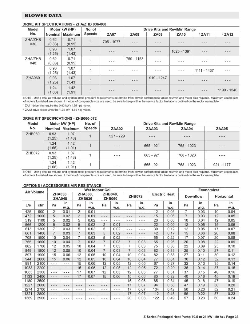
Z-Series Packaged Heat Pump 10.5 to 21 kW - 50 hz / Page 33
BLOWER DATA
DRIVE KIT SPECIFICATIONS - ZHA/ZHB 036-060Model
No.Motor kW (HP) No. of
SpeedsDrive Kits and Rev/Min Range
Nominal Maximum ZA07 ZA08 ZA09 ZA10 1 ZA11 2 ZA12ZHA/ZHB
0360.62
(0.83)0.71
(0.95) 1 705 - 1077 - - - - - - - - - - - - - - -
0.93 (1.25)
1.07 (1.43) 1 - - - - - - - - - 1025 - 1391 - - - - - -
ZHA/ZHB 048
0.62 (0.83)
0.71 (0.95) 1 - - - 759 - 1158 - - - - - - - - - - - -
0.93 (1.25)
1.07 (1.43) 1 - - - - - - - - - - - - 1111 - 1437 - - -
ZHA060 0.93 (1.25)
1.07 (1.43) 1 - - - - - - 919 - 1247 - - - - - - - - -
1.24 (1.66)
1.42 (1.91) 1 - - - - - - - - - - - - - - - 1190 - 1540
NOTE - Using total air volume and system static pressure requirements determine from blower performance tables rev/min and motor size required. Maximum usable size of motors furnished are shown. If motors of comparable size are used, be sure to keep within the service factor limitations outlined on the motor nameplate.1 ZA11 drive kits require the 0.93 kW (1.25 hp) motor.2 ZA12 drive kit requires the 1.24 kW (1.66 hp) motor.
DRIVE KIT SPECIFICATIONS - ZHB060-072Model
No.Motor kW (HP) No. of
SpeedsDrive Kits and Rev/Min Range
Nominal Maximum ZAA02 ZAA03 ZAA04 ZAA05ZHB060 0.93
(1.25)1.07
(1.43) 1 527 - 729 - - - - - - - - -
1.24 (1.66)
1.42 (1.91) 1 - - - 665 - 921 768 - 1023 - - -
ZHB072 0.93 (1.25)
1.07 (1.43) 1 - - - 665 - 921 768 - 1023 - - -
1.24 (1.66)
1.42 (1.91) 1 - - - 665 - 921 768 - 1023 921 - 1177
NOTE - Using total air volume and system static pressure requirements determine from blower performance tables rev/min and motor size required. Maximum usable size of motors furnished are shown. If motors of comparable size are used, be sure to keep within the service factor limitations outlined on the motor nameplate.
OPTIONS / ACCESSORIES AIR RESISTANCE
Air Volume Wet Indoor CoilElectric Heat
EconomizerZHA036, ZHA048
ZHA060, ZHB036
ZHB048, ZHB060 ZHB072 Downflow Horizontal
L/s cfm Pa in. w.g. Pa in.
w.g. Pa in. w.g. Pa in.
w.g. Pa in. w.g. Pa in.
w.g. Pa in. w.g.
425 900 2 0.01 2 0.01 - - - - - - - - - - - - 12 0.05 7 0.03 10 0.04472 1000 5 0.02 2 0.01 - - - - - - - - - - - - 15 0.06 7 0.03 12 0.05519 1100 5 0.02 5 0.02 - - - - - - - - - - - - 20 0.08 10 0.04 12 0.05566 1200 5 0.02 5 0.02 2 0.01 - - - - - - 22 0.09 12 0.05 15 0.06613 1300 7 0.03 5 0.02 5 0.02 - - - - - - 30 0.12 12 0.05 17 0.07661 1400 7 0.03 7 0.03 5 0.02 - - - - - - 42 0.17 15 0.06 20 0.08708 1500 10 0.04 7 0.03 5 0.02 - - - - - - 55 0.22 17 0.07 20 0.08755 1600 10 0.04 7 0.03 7 0.03 7 0.03 65 0.26 20 0.08 22 0.09802 1700 12 0.05 10 0.04 7 0.03 7 0.03 75 0.30 22 0.09 25 0.10849 1800 12 0.05 10 0.04 7 0.03 7 0.03 82 0.33 25 0.10 27 0.11897 1900 15 0.06 12 0.05 10 0.04 10 0.04 82 0.33 27 0.11 30 0.12944 2000 15 0.06 12 0.05 10 0.04 10 0.04 77 0.31 30 0.12 32 0.13991 2100 - - - - - - 15 0.06 12 0.05 12 0.05 67 0.27 32 0.13 35 0.141038 2200 - - - - - - 15 0.06 12 0.05 12 0.05 72 0.29 35 0.14 37 0.151085 2300 - - - - - - 17 0.07 12 0.05 12 0.05 77 0.31 37 0.15 40 0.161133 2400 - - - - - - 17 0.07 15 0.06 15 0.06 80 0.32 40 0.16 45 0.181180 2500 - - - - - - - - - - - - - - - - - - 15 0.06 85 0.34 45 0.18 47 0.191227 2600 - - - - - - - - - - - - - - - - - - 17 0.07 94 0.38 47 0.19 50 0.201274 2700 - - - - - - - - - - - - - - - - - - 17 0.07 104 0.42 50 0.20 52 0.211321 2800 - - - - - - - - - - - - - - - - - - 17 0.07 112 0.45 55 0.22 57 0.231369 2900 - - - - - - - - - - - - - - - - - - 20 0.08 122 0.49 57 0.23 60 0.24

Z-Series Packaged Heat Pump 10.5 to 21 kW - 50 hz / Page 34
BLOWER DATA
POWER EXHAUST FAN PERFORMANCEReturn Air System Static Pressure Air Volume ExhaustedPa in. w.g. L/s cfm0 0.00 880 1865
12 0.05 842 178525 0.10 807 171037 0.15 769 163050 0.20 729 154562 0.25 684 145075 0.30 637 135087 0.35 585 1240
CEILING DIFFUSERS AIR RESISTANCEAir Volume RTD9-65S Step–Down Diffuser FD9-65S
Flush Diffuser
RTD11-95S Step–Down Diffuser FD11-95S Flush
Diffuser2 Ends Open
1 Side & 2 Ends Open
All Ends & Sides Open
2 Ends Open
1 Side & 2 Ends Open
All Ends & Sides Open
L/s cfm Pa in. w.g. Pa in. w.g. Pa in. w.g. Pa in. w.g. Pa in. w.g. Pa in. w.g. Pa in. w.g. Pa in. w.g.375 800 37 0.15 32 0.13 27 0.11 27 0.11 - - - - - - - - - - - - - - - - - - - - - - - -470 1000 47 0.19 40 0.16 35 0.14 35 0.14 - - - - - - - - - - - - - - - - - - - - - - - -565 1200 62 0.25 50 0.20 42 0.17 42 0.17 - - - - - - - - - - - - - - - - - - - - - - - -660 1400 82 0.33 65 0.26 50 0.20 50 0.20 - - - - - - - - - - - - - - - - - - - - - - - -755 1600 107 0.43 80 0.32 50 0.20 50 0.24 - - - - - - - - - - - - - - - - - - - - - - - -850 1800 139 0.56 99 0.40 75 0.30 75 0.30 32 0.13 27 0.11 22 0.09 22 0.09945 2000 182 0.73 124 0.50 90 0.36 90 0.36 37 0.15 32 0.13 27 0.11 25 0.101040 2200 236 0.95 157 0.63 109 0.44 109 0.44 45 0.18 37 0.15 30 0.12 30 0.121130 2400 - - - - - - - - - - - - - - - - - - - - - - - - 52 0.21 45 0.18 37 0.15 35 0.141225 2600 - - - - - - - - - - - - - - - - - - - - - - - - 60 0.24 52 0.21 45 0.18 42 0.171320 2800 - - - - - - - - - - - - - - - - - - - - - - - - 67 0.27 60 0.24 52 0.21 50 0.201415 3000 - - - - - - - - - - - - - - - - - - - - - - - - 80 0.32 72 0.29 62 0.25 62 0.251510 3200 - - - - - - - - - - - - - - - - - - - - - - - - 102 0.41 92 0.37 80 0.32 77 0.311605 3400 - - - - - - - - - - - - - - - - - - - - - - - - 124 0.50 112 0.45 97 0.39 92 0.371700 3600 - - - - - - - - - - - - - - - - - - - - - - - - 152 0.61 134 0.54 119 0.48 109 0.44
CEILING DIFFUSER AIR THROW DATAAir Volume 1 Effective ThrowModel No. RTD9-65S FD9-65S
L/s cfm m ft. m ft.375 800 3 - 5 10 - 17 4 - 5 14 - 18470 1000 3 - 5 10 - 17 5 - 6 15 - 20565 1200 3 - 5 11 - 18 5 - 7 16 - 22660 1400 4 - 6 12 - 19 5 - 7 17 - 24755 1600 4 - 6 12 - 20 5 - 8 18 - 25850 1800 4 - 6 13 - 21 6 - 9 20 - 28945 2000 4 - 7 14 - 23 6 - 9 21 - 291040 2200 5 - 8 16 - 25 7 - 9 22 - 30
Model No. RTD11-95S FD11-95S1225 2600 7 - 9 24 - 29 6 - 7 19 - 241320 2800 8 - 9 25 - 30 6 - 9 20 - 281415 3000 8 - 10 27 - 33 6 - 9 21 - 291510 3200 9 - 11 28 - 35 7 9 22 - 291605 3400 9 - 11 30 - 37 7 - 9 22 - 301700 3600 8 - 10 25 - 33 7 - 8 22 - 24
1 Effective throw based on terminal velocities of 23 m per minute ( 75 ft. per minute).

Z-Series Packaged Heat Pump 10.5 to 21 kW - 50 hz / Page 35
ELECTRICAL/ELECTRIC HEAT DATA - ZHAZHA036S4 ZHA048S4 ZHA060S4
1 Voltage - 50hz with Neutral 380/420V - 3 Ph 380/420V - 3 Ph 380/420V - 3 Ph
Compressor Rated Load Amps 4 5.5 8
Locked Rotor Amps 31 37 59
Outdoor Fan Motor
Full Load Amps 0.9 0.9 1
Power Exhaust (1) 0.37 kW
Full Load Amps 0.6 0.6 0.6
Indoor Blower Motor
kW 0.62 0.93 0.62 0.93 0.93 1.24
Full Load Amps 1.5 2 1.6 2 2 2.92 Maximum
Overcurrent Protection
Unit Only 15 15 15 15 20 20
With (1) 0.37 kW Power Exhaust
15 15 15 15 20 20
3 Minimum Circuit Ampacity
Unit Only 8 8 10 10 13 14
With (1) 0.37 kW Power Exhaust
9 9 10 11 14 15
ELECTRIC HEAT DATAElectric Heat Voltage 420V 420V 420V 420V 420V 420V2 Maximum
Overcurrent Protection
Unit+ 4 Electric Heat
3.8 kW 15 15 20 20 25 25
5.7 kW 20 20 20 20 25 25
7.7 kW 25 25 25 25 30 30
11.5 kW 30 30 30 30 35 35
17.2 kW - - - - - - 40 40 45 453 Minimum
Circuit Ampacity
Unit+ 4 Electric Heat
3.8 kW 15 15 16 17 20 21
5.7 kW 18 18 20 20 23 24
7.7 kW 21 22 23 23 27 28
11.5 kW 28 28 30 30 33 34
17.2 kW - - - - - - 39 40 43 442 Maximum
Overcurrent Protection
Unit+ 4 Electric Heat
and (1) 0.37 kW
Power Exhaust
3.8 kW 15 20 20 20 25 25
5.7 kW 20 20 20 25 25 30
7.7 kW 25 25 25 25 30 30
11.5 kW 30 30 30 35 35 35
17.2 kW - - - - - - 40 40 45 453 Minimum
Circuit Ampacity
Unit+ 4 Electric Heat
and (1) 0.37 kW
Power Exhaust
3.8 kW 15 16 17 17 21 22
5.7 kW 18 19 20 21 24 25
7.7 kW 22 22 24 24 27 28
11.5 kW 28 29 30 31 34 35
17.2 kW - - - - - - 40 40 44 45
ELECTRIC HEAT ACCESSORIES
Unit Fuse Block Unit Only 10A29 10A29 10A29 10A29 10A29 10A29
Unit + Power Exhaust 10A29 10A29 10A29 10A29 10A29 10A291 Extremes of operating range are plus and minus 10% of line voltage.2 Heating, Air Conditioning, Refrigeration type breaker or fuse.3 Refer to local electrical code to determine wire, fuse and disconnect size requirements.4 Nominal kW based on 420V-3ph-50hz.

Z-Series Packaged Heat Pump 10.5 to 21 kW - 50 hz / Page 36
ELECTRICAL/ELECTRIC HEAT DATA - ZHBZHB036S4 ZHB048S4 ZHB060S4 ZHB072S4
1 Voltage - 50hz with Neutral 380/420V - 3 Ph 380/420V - 3 Ph 380/420V - 3 Ph 380/420V - 3 PhCompressor Rated Load Amps 4 5.5 8 10.6
Locked Rotor Amps 31 37 59 74Outdoor Fan Motor
Full Load Amps 0.6 0.9 1 1.3
Power Exhaust (1) 0.37 kW
Full Load Amps 0.6 0.6 0.6 0.6
Indoor Blower Motor
kW 0.62 0.93 0.62 0.93 0.93 1.24 0.93 1.24Full Load Amps 1.6 2 1.6 2 2 2.9 2 2.9
2 Maximum Overcurrent Protection
Unit Only 15 15 15 15 20 20 25 25With (1) 0.37 kW
Power Exhaust15 15 15 15 20 20 25 25
3 Minimum Circuit Ampacity
Unit Only 8 8 10 10 13 14 17 18With (1) 0.37 kW
Power Exhaust8 8 10 11 14 15 18 19
ELECTRIC HEAT DATAElectric Heat Voltage 420V 420V 420V 420V 420V 420V 420V 420V2 Maximum
Overcurrent Protection
Unit+ 4 Electric Heat
3.8 kW 15 15 20 20 25 25 - - - - - -5.7 kW 20 20 20 20 25 25 35 357.7 kW 25 25 25 25 30 30 35 35
11.5 kW 30 30 30 30 35 35 40 4017.2 kW - - - - - - 40 40 45 45 50 50
23 kW - - - - - - - - - - - - - - - - - - 60 603 Minimum
Circuit Ampacity
Unit+ 4 Electric Heat
3.8 kW 14 15 16 17 20 21 - - - - - -5.7 kW 18 18 20 20 23 24 27 287.7 kW 21 21 23 23 27 28 30 31
11.5 kW 27 28 30 30 33 34 37 3817.2 kW - - - - - - 39 40 43 44 47 48
23 kW - - - - - - - - - - - - - - - - - - 57 572 Maximum
Overcurrent Protection
Unit+ 4 Electric Heat
and (1) 0.37
Power Exhaust
3.8 kW 15 15 20 20 25 25 - - - - - -5.7 kW 20 20 20 25 25 30 35 357.7 kW 25 25 25 25 30 30 35 35
11.5 kW 30 30 30 35 35 35 40 4017.2 kW - - - - - - 40 40 45 45 50 50
23 kW - - - - - - - - - - - - - - - - - - 60 603 Minimum
Circuit Ampacity
Unit+ 4 Electric Heat
and (1) 0.37
Power Exhaust
3.8 kW 15 15 17 17 21 22 - - - - - -5.7 kW 18 19 20 21 24 25 28 287.7 kW 21 22 24 24 27 28 31 32
11.5 kW 28 28 30 31 34 35 37 3817.2 kW - - - - - - 40 40 44 45 47 48
23 kW - - - - - - - - - - - - - - - - - - 57 58
ELECTRIC HEAT ACCESSORIESUnit Fuse Block Unit Only 10A29 10A29 10A29 10A29 10A29 10A29 10A29 10A29
Unit + Power Exhaust 10A29 10A29 10A29 10A29 10A29 10A29 10A29 10A291 Extremes of operating range are plus and minus 10% of line voltage.2 Heating, Air Conditioning, Refrigeration type breaker or fuse.3 Refer to local electrical code to determine wire, fuse and disconnect size requirements.4 Nominal kW based on 420V-3ph-50hz.

Z-Series Packaged Heat Pump 10.5 to 21 kW - 50 hz / Page 37
ELECTRIC HEAT CAPACITIES
Input Voltage
3.8 kW 5.7 kW 7.7 kWNo of
StageskW
inputBtuh
OutputNo of
StageskW
inputBtuh
OutputNo of
StageskW
inputBtuh
Output380 1 3.1 10 700 1 4.7 16 000 1 6.3 21 400400 1 3.5 11 800 1 5.2 17 800 1 6.9 23 700420 1 3.8 13 100 1 5.7 19 600 1 7.7 26 100
Input Voltage
11.5 kW 17.2 kW 23 kWNo of
StageskW
inputBtuh
OutputNo of
StageskW
inputBtuh
OutputNo of
StageskW
inputBtuh
Output380 1 9.4 32 100 1 14.1 48 100 1 18.8 64 200400 1 10.4 35 500 1 15.6 53 300 1 20.9 71 400420 1 11.5 39 200 1 17.2 58 800 1 23.0 78 500
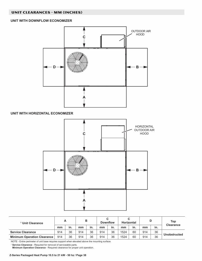
Z-Series Packaged Heat Pump 10.5 to 21 kW - 50 hz / Page 38
UNIT CLEARANCES - MM (INCHES)
BD
A
COUTDOOR AIR
HOOD
BD
C
A
HORIZONTALOUTDOOR AIR
HOOD
UNIT WITH DOWNFLOW ECONOMIZER
UNIT WITH HORIZONTAL ECONOMIZER
1 Unit ClearanceA B C
DownflowC
Horizontal D Top Clearance
mm in. mm in. mm in. mm in. mm in.Service Clearance 914 36 914 36 914 36 1524 60 914 36
UnobstructedMinimum Operation Clearance 914 36 914 36 914 36 1524 60 914 36NOTE - Entire perimeter of unit base requires support when elevated above the mounting surface.1 Service Clearance - Required for removal of serviceable parts.
Minimum Operation Clearance - Required clearance for proper unit operation.

Z-Series Packaged Heat Pump 10.5 to 21 kW - 50 hz / Page 39
OUTDOOR SOUND DATA Unit
Model No.Octave Band Linear Sound Power Levels dBA, re 10-12 Watts - Center Frequency - Hz 1 Sound Rating
Number (SRN) (dBA)125 250 500 1000 2000 4000 8000
ZHA036 82 79 78 74 70 66 61 79
ZHA048 82 79 78 74 70 66 61 79
ZHA060 86 83 82 77 73 70 67 83
ZHB036 82 79 78 74 70 66 61 79
ZHB048 77 77 76 72 67 63 57 77
ZHB060 85 81 81 76 71 69 67 82
ZHB072 85 85 84 80 75 72 70 861 Sound Rating Number according to ANSI/AHRI Standard 270-2008. “SRN” is the overall A-Weighted Sound Power Level, (LWA), dBA (100 Hz to 10,000 Hz).
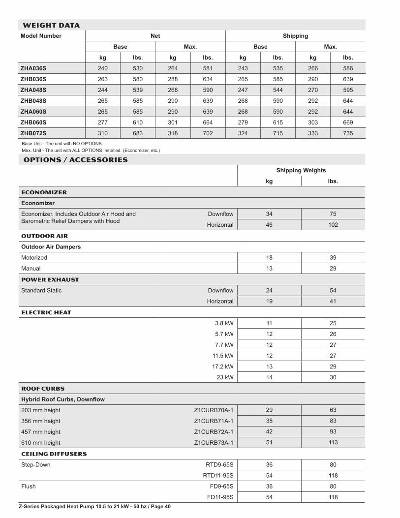
Z-Series Packaged Heat Pump 10.5 to 21 kW - 50 hz / Page 40
OPTIONS / ACCESSORIESShipping Weights
kg lbs.
ECONOMIZER
Economizer
Economizer, Includes Outdoor Air Hood and Barometric Relief Dampers with Hood
Downflow 34 75
Horizontal 46 102
OUTDOOR AIR
Outdoor Air Dampers
Motorized 18 39
Manual 13 29
POWER EXHAUST
Standard Static Downflow 24 54
Horizontal 19 41
ELECTRIC HEAT
3.8 kW 11 25
5.7 kW 12 26
7.7 kW 12 27
11.5 kW 12 27
17.2 kW 13 29
23 kW 14 30
ROOF CURBS
Hybrid Roof Curbs, Downflow
203 mm height Z1CURB70A-1 29 63
356 mm height Z1CURB71A-1 38 83
457 mm height Z1CURB72A-1 42 93
610 mm height Z1CURB73A-1 51 113
CEILING DIFFUSERS
Step-Down RTD9-65S 36 80
RTD11-95S 54 118
Flush FD9-65S 36 80
FD11-95S 54 118
WEIGHT DATAModel Number Net Shipping
Base Max. Base Max.
kg lbs. kg lbs. kg lbs. kg lbs.
ZHA036S 240 530 264 581 243 535 266 586
ZHB036S 263 580 288 634 265 585 290 639
ZHA048S 244 539 268 590 247 544 270 595
ZHB048S 265 585 290 639 268 590 292 644
ZHA060S 265 585 290 639 268 590 292 644
ZHB060S 277 610 301 664 279 615 303 669
ZHB072S 310 683 318 702 324 715 333 735
Base Unit - The unit with NO OPTIONS.Max. Unit - The unit with ALL OPTIONS Installed. (Economizer, etc.)
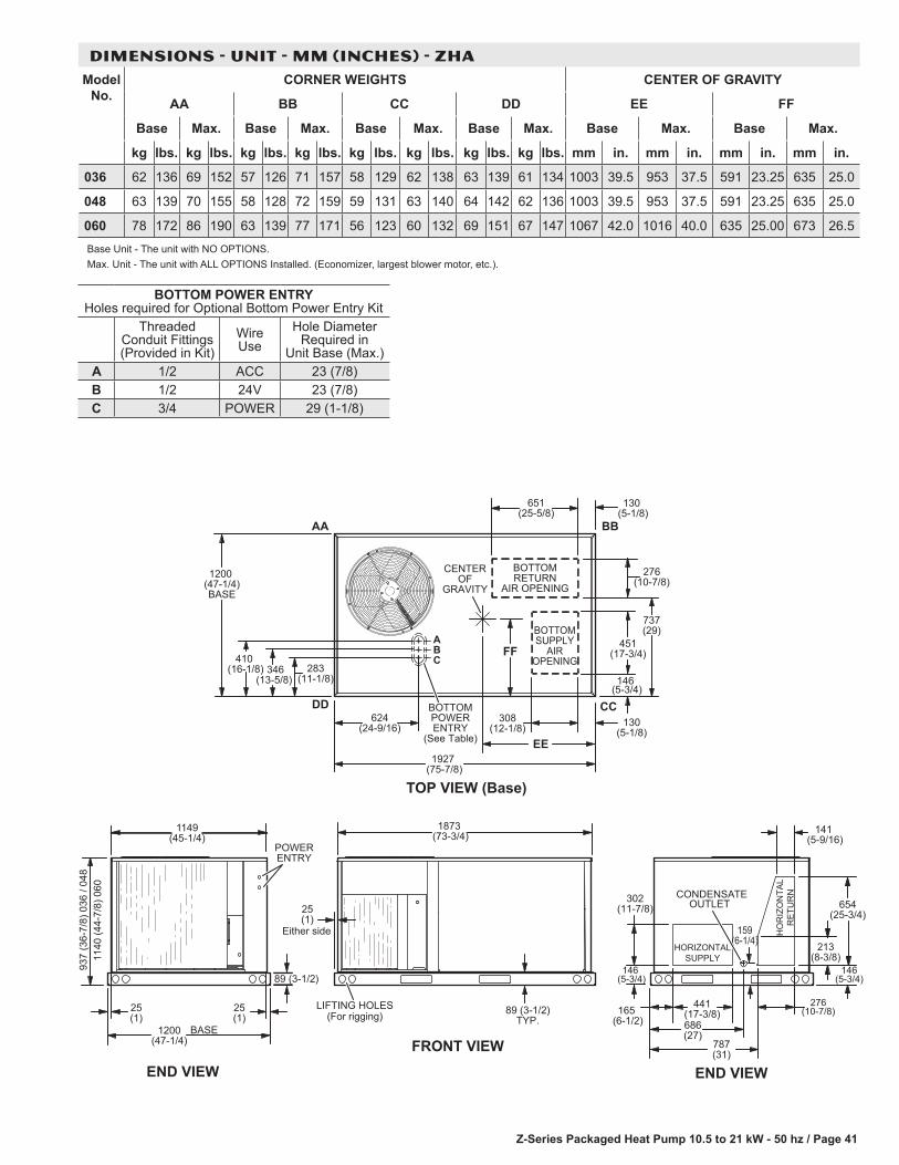
Z-Series Packaged Heat Pump 10.5 to 21 kW - 50 hz / Page 41
BOTTOM POWER ENTRY Holes required for Optional Bottom Power Entry Kit
Threaded Conduit Fittings (Provided in Kit)
Wire Use
Hole Diameter Required in
Unit Base (Max.)A 1/2 ACC 23 (7/8)B 1/2 24V 23 (7/8)C 3/4 POWER 29 (1-1/8)
146(5-3/4)
1149
FRONT VIEW
89 (3-1/2)TYP.
END VIEW
Either side
1873 (73-3/4)
END VIEW
25(1)
LIFTING HOLES(For rigging)
(45-1/4)
1200(47-1/4)
BASE
POWERENTRY
89 (3-1/2)
302(11-7/8)
146 (5-3/4)
441(17-3/8)165
(6-1/2) 686(27)
787(31)
CONDENSATEOUTLET
159(6-1/4)
654(25-3/4)
213(8-3/8)
276(10-7/8)
141 (5-9/16)
937
(36-
7/8)
036
/ 04
811
40 (4
4-7/
8) 0
60
276(10-7/8)
651 (25-5/8)
130 (5-1/8)
1927 (75-7/8)
TOP VIEW (Base)
624 (24-9/16)
DD CC
BBAA
308 (12-1/8) 130
(5-1/8)EE
BOTTOMSUPPLY
AIROPENING
BOTTOMRETURN
AIR OPENING
FF451
(17-3/4)
CENTEROF
GRAVITY
737(29)
146 (5-3/4)
BA
C
BOTTOMPOWERENTRY
(See Table)
410 (16-1/8)
1200 (47-1/4)BASE
346 (13-5/8)
283 (11-1/8)
HORIZONTALSUPPLY
HO
RIZ
ON
TAL
RE
TUR
N
25(1)
25(1)
DIMENSIONS - UNIT - MM (INCHES) - ZHAModel
No.CORNER WEIGHTS CENTER OF GRAVITY
AA BB CC DD EE FF
Base Max. Base Max. Base Max. Base Max. Base Max. Base Max.
kg lbs. kg lbs. kg lbs. kg lbs. kg lbs. kg lbs. kg lbs. kg lbs. mm in. mm in. mm in. mm in.
036 62 136 69 152 57 126 71 157 58 129 62 138 63 139 61 134 1003 39.5 953 37.5 591 23.25 635 25.0
048 63 139 70 155 58 128 72 159 59 131 63 140 64 142 62 136 1003 39.5 953 37.5 591 23.25 635 25.0
060 78 172 86 190 63 139 77 171 56 123 60 132 69 151 67 147 1067 42.0 1016 40.0 635 25.00 673 26.5
Base Unit - The unit with NO OPTIONS.Max. Unit - The unit with ALL OPTIONS Installed. (Economizer, largest blower motor, etc.).
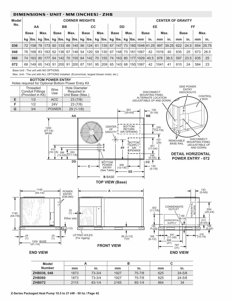
Z-Series Packaged Heat Pump 10.5 to 21 kW - 50 hz / Page 42
BOTTOM POWER ENTRY Holes required for Optional Bottom Power Entry Kit
Threaded Conduit Fittings (Provided in Kit)
Wire Use
Hole Diameter Required in
Unit Base (Max.)E 1/2 ACC 23 (7/8)F 1/2 24V 23 (7/8)G 3/4 POWER 29 (1-1/8)
DIMENSIONS - UNIT - MM (INCHES) - ZHBModel
No.CORNER WEIGHTS CENTER OF GRAVITY
AA BB CC DD EE FF
Base Max. Base Max. Base Max. Base Max. Base Max. Base Max.
kg lbs. kg lbs. kg lbs. kg lbs. kg lbs. kg lbs. kg lbs. kg lbs. mm in. mm in. mm in. mm in.
036 72 158 78 173 60 133 66 145 56 124 61 135 67 147 73 160 1048 41.25 997 39.25 622 24.5 654 25.75
048 76 168 83 183 62 136 67 148 54 120 59 130 67 148 73 161 1067 42 1016 40 635 25 673 26.5
060 74 163 80 177 64 142 70 155 64 142 70 155 74 163 80 177 1029 40.5 978 38.5 597 23.5 635 25
072 68 149 65 143 91 200 91 200 87 191 95 209 65 143 68 150 1067 42 1041 41 610 24 584 23
Base Unit - The unit with NO OPTIONS.Max. Unit - The unit with ALL OPTIONS Installed. (Economizer, largest blower motor, etc.)
25 (1)
146 (5-3/4)
(
FRONT VIEW
89 (3-1/2)TYP.
END VIEW
25 (1)
Either side
END VIEW
25 (1)
LIFTING HOLES(For rigging)
1149 (45-1/4)
1200 (47-1/4)
BASE
POWERENTRY
(036-060)
89 (3-1/2)
302 (11-7/8)
146 (5-3/4)
441 (17-3/8)165
(6-1/2) 686 (27)
787 (31)
CONDENSATEOUTLET
159 (6-1/4)
654 (25-3/4)
213 (8-3/8)
276 (10-7/8)
143 (5-5/8)
276 (10-7/8)
651 (25-5/8)
130 (5-1/8)
TOP VIEW (Base)
DD CC
BBAA
308 (12-1/8) 130
(5-1/8)EE
BOTTOMSUPPLY
AIROPENING
BOTTOMRETURN
AIR OPENING
FF451
(17-3/4)
CENTEROF
GRAVITY
737 (29)
146 (5-3/4)
FE
G
BOTTOMPOWERENTRY
(See Table)
410 (16-1/8)
1200 (47-1/4)BASE
346(13-5/8)
283 (11-1/8)
HORIZONTALSUPPLY
HO
RIZ
ON
TAL
RE
TUR
NA
1140 (44-7/8)
B BASE
C
DETAIL HORIZONTALPOWER ENTRY - 072
DISCONNECTMOUNTING PANEL
ALTERNATE LOCATION(ADJUSTABLE UP AND DOWN)
SIDE POWER ENTRY
KNOCKOUTSCONTROL
BOX
DISCONNECTMOUNTING PANEL(ADJUSTABLE UP
AND DOWN)
REMOVABLE BASE RAIL
Model Number
A B Cmm in. mm in. mm in.
ZHB036, 048 1873 73-3/4 1927 75-7/8 625 24-5/8ZHB060 1873 73-3/4 1927 75-7/8 625 24-5/8ZHB072 2115 83-1/4 2165 85-1/4 864 34
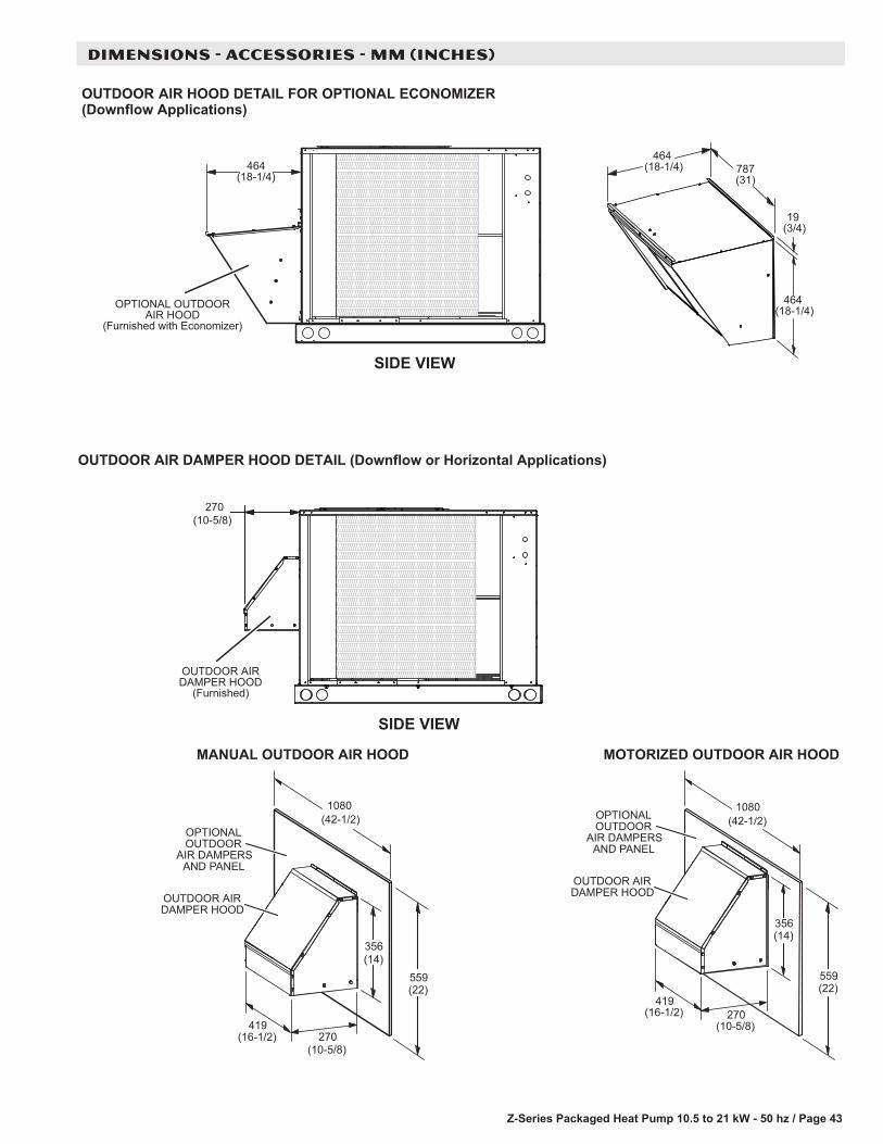
Z-Series Packaged Heat Pump 10.5 to 21 kW - 50 hz / Page 43
DIMENSIONS - ACCESSORIES - MM (INCHES)
787(31)
OUTDOOR AIR HOOD DETAIL FOR OPTIONAL ECONOMIZER(Downflow Applications)
SIDE VIEW
270 (10-5/8)
OUTDOOR AIRDAMPER HOOD
(Furnished)
OPTIONAL OUTDOORAIR HOOD
(Furnished with Economizer)
SIDE VIEW
464 (18-1/4)
464 (18-1/4)
19 (3/4)
464 (18-1/4)
OUTDOOR AIR DAMPER HOOD DETAIL (Downflow or Horizontal Applications)
(16-1/2)419
(22)559
(42-1/2)1080
(14)356
(10-5/8)270
OUTDOOR AIRDAMPER HOOD
OPTIONALOUTDOOR
AIR DAMPERSAND PANEL
MANUAL OUTDOOR AIR HOOD MOTORIZED OUTDOOR AIR HOOD
(16-1/2)419
(22)559
(42-1/2)1080
(14)356
(10-5/8)270
OUTDOOR AIRDAMPER HOOD
OPTIONALOUTDOOR
AIR DAMPERSAND PANEL

Z-Series Packaged Heat Pump 10.5 to 21 kW - 50 hz / Page 44
DIMENSIONS - ACCESSORIES - MM (INCHES)
BACK VIEWEND VIEW
1873 (73-3/4) 036-060
HORIZONTALSUPPLY AIR
OPENING
This opening not used inHorizontal Applications
with Economizer
HORIZONTALRETURN AIR
OPENING
(18-1/4)463(38-1/4)
971
302(11-7/8)
146 (5-3/4)
441(17-3/8)165
(6-1/2)
HORIZONTALECONOMIZER
LOCATION
TOP VIEW
RETURN AIR DUCT INLET(Field Fabricated - Must be sized to
accommodate Barometric Relief Hood and Return Air Requirements)
FRESH AIROPENING
EXHAUSTOPENING
OUTDOOR AIR/BAROMETRICRELIEF HOOD(Furnished with
Economizer)
Note - Return Air Duct and Transition must be supported.
OUTDOOR AIR HOOD DETAIL WITH OPTIONAL ECONOMIZER AND BAROMETRIC RELIEF DAMPERS(Horizontal Applications)
(31)787
406(16)
406(16)
2115 (83/1-4) 072

Z-Series Packaged Heat Pump 10.5 to 21 kW - 50 hz / Page 45
DIMENSIONS - ACCESSORIES - MM (INCHES)
NOTE - Roof deck may be omitted within confines of curb.
TYPICAL FLASHING DETAIL FOR ROOF CURB
ROOF CURB(Extends around entire
perimeter of unit)
FIBERGLASSINSULATION
(Furnished)COUNTER FLASHING(Field Supplied)
BASE BOTTOM
RIGID INSULATION(Field Supplied)
ROOFINGMATERIAL
CANT STRIP(Field Supplied)
PACKAGEDUNIT
NAILER STRIP(Furnished)
DETAIL ROOF CURB
FACTORY INSTALLEDPERIMETER WOODNAILER STRIP
RETURNOPENING
SUPPLYOPENING
DECK PANS (3)
HYBRID ROOF CURBS - DOUBLE DUCT OPENING
356(14)356(14)
441-3/4
13 (1/2)
44 (1-3/4)
1803(71)
814(32-1/16)
381(15)
923-5/8
43717-3/16
107542-5/16
51420-1/4
203 (8)356 (14)457 (18)610 (24)
203 (8)356 (14)457 (18)610 (24)

Z-Series Packaged Heat Pump 10.5 to 21 kW - 50 hz / Page 46
DIMENSIONS - ACCESSORIES - MM (INCHES)
COMBINATION CEILING SUPPLY AND RETURN DIFFUSERSSTEP-DOWN CEILING DIFFUSER FLUSH CEILING DIFFUSER
L A
J
C
HH
DG
G
FE
B
K
51 (2)
A
C
HH
DG
G
FE
B
51 (2)
Model Number RTD9-65S RTD11-95SA mm 1159 1159
in. 47-5/8 47-5/8B mm 600 752
in. 23-5/8 29-5/8C mm 289 365
in. 11-3/8 14-3/8D mm 546 699
in. 21-1/2 27-1/2E mm 1156 1158
in. 45-1/2 45-1/2F mm 572 572
in. 22-1/2 22-1/2G mm 292 292
in. 11-1/2 11-1/2H mm 273 349
in. 10-3/4 13-3/4J mm 1156 1156
in. 45-1/2 45-1/2K mm 546 699
in. 21-1/2 27-1/2L mm 181 206
in. 7-1/8 8-1/8Duct Size mm 457 round 508 round
in. 18 round 20 round
Model Number FD9-65S FD11-95SA mm 1159 1159
in. 47-5/8 47-5/8B mm 600 752
in. 23-5/8 29-5/8C mm 343 422
in. 13-1/2 16-5/8D mm 533 686
in. 21 27E mm 1143 1143
in. 45 45F mm 572 572
in. 22-1/2 22-1/2G mm 286 286
in. 11-1/4 11-1/4H mm 267 343
in. 10-1/2 13-1/2Duct Size mm 457 round 508 round
in. 18 round 20 round


REVISIONS
REVISIONS
Sections Description of Change
Document Added new unit ZHB072.
NOTE - Due to Allied Commercial ongoing commitment to quality, Specifications, Ratings and Dimensions subject to change without notice and without incurring liability. Improper installation, adjustment, alteration, service or maintenance can cause property damage or personal injury. Installation and service must be performed by a qualified installer and servicing agency.
©2017 Allied Air Enterprises LLC, a Lennox International Inc. Company
Visit us at www.allied-commercial.com
For the latest technical information, visit us at www.allied-commercial.com
Contact us at 1-800-738-4000