1046736-07 - Vantage Modular Gun Control...
62
Vantage r Modular Gun Control System Customer Product Manual Part 1046736−07 Issued 03/20 NORDSON CORPORATION • AMHERST, OHIO • USA For parts and technical support, call the Finishing Customer Support Center at (800) 433-9319. This document is available on the Internet at http://emanuals.nordson.com/finishing
Transcript of 1046736-07 - Vantage Modular Gun Control...

Vantage� Modular Gun Control System
Customer Product ManualPart 1046736−07
Issued 03/20
NORDSON CORPORATION • AMHERST, OHIO • USA
For parts and technical support, call the Finishing Customer Support Center at (800) 433-9319.
This document is available on the Internet at http://emanuals.nordson.com/finishing

Part 1046736−07 � 2020 Nordson Corporation
Table of ContentsSafety 1-1. . . . . . . . . . . . . . . . . . . . . . . . . . . . . . . . . . . .Introduction 1-1. . . . . . . . . . . . . . . . . . . . . . . . . . . . . . .Qualified Personnel 1-1. . . . . . . . . . . . . . . . . . . . . . . .Intended Use 1-1. . . . . . . . . . . . . . . . . . . . . . . . . . . . . .Regulations and Approvals 1-1. . . . . . . . . . . . . . . . . .Personal Safety 1-2. . . . . . . . . . . . . . . . . . . . . . . . . . .Fire Safety 1-2. . . . . . . . . . . . . . . . . . . . . . . . . . . . . . . .Grounding 1-3. . . . . . . . . . . . . . . . . . . . . . . . . . . . . . . .Action in the Event of a Malfunction 1-3. . . . . . . . . .Disposal 1-3. . . . . . . . . . . . . . . . . . . . . . . . . . . . . . . . . .
Description 2-1. . . . . . . . . . . . . . . . . . . . . . . . . . . . . . .Introduction 2-1. . . . . . . . . . . . . . . . . . . . . . . . . . . . . . . .Master Control Unit 2-1. . . . . . . . . . . . . . . . . . . . . . . .Spray Gun Controls and Indicators 2-2. . . . . . . . . . .
Front Panel 2-2. . . . . . . . . . . . . . . . . . . . . . . . . . . . .Keypad 2-3. . . . . . . . . . . . . . . . . . . . . . . . . . . . . .Display 2-4. . . . . . . . . . . . . . . . . . . . . . . . . . . . . .
Back Panel 2-4. . . . . . . . . . . . . . . . . . . . . . . . . . . . .Base Assembly 2-5. . . . . . . . . . . . . . . . . . . . . . . . . . . .Operating Modes 2-6. . . . . . . . . . . . . . . . . . . . . . . . . . .Specifications 2-6. . . . . . . . . . . . . . . . . . . . . . . . . . . . . .
Installation 3-1. . . . . . . . . . . . . . . . . . . . . . . . . . . . . . . .Mounting 3-1. . . . . . . . . . . . . . . . . . . . . . . . . . . . . . . . . .Electrical Connections 3-1. . . . . . . . . . . . . . . . . . . . . .Spray Gun Cable/Adapter Installation 3-3. . . . . . . . .
Sure Coat or Versa Spray II Automatic Spray Gun Cables 3-3. . . . . . . . . . . . .Tribomatic II Automatic Spray Gun Adapters 3-5.
Trigger Configuration 3-6. . . . . . . . . . . . . . . . . . . . . . .Pneumatic Connections 3-7. . . . . . . . . . . . . . . . . . . . .External Trigger Connections 3-7. . . . . . . . . . . . . . . .
Operation 4-1. . . . . . . . . . . . . . . . . . . . . . . . . . . . . . . . .Startup 4-2. . . . . . . . . . . . . . . . . . . . . . . . . . . . . . . . . . .Initial Gun Usage 4-4. . . . . . . . . . . . . . . . . . . . . . . . . . .Air Pressure Adjustments 4-5. . . . . . . . . . . . . . . . . . . .
Flow Rate Air Pressure 4-5. . . . . . . . . . . . . . . . . . .Atomizing Air Pressure 4-5. . . . . . . . . . . . . . . . . . .Fluidizing Air Pressure 4-6. . . . . . . . . . . . . . . . . . . .
Shutdown 4-6. . . . . . . . . . . . . . . . . . . . . . . . . . . . . . . . .Daily Maintenance 4-6. . . . . . . . . . . . . . . . . . . . . . . . . .
Troubleshooting 5-1. . . . . . . . . . . . . . . . . . . . . . . . . .Wiring Diagrams 5-4. . . . . . . . . . . . . . . . . . . . . . . . . . .
Repair 6-1. . . . . . . . . . . . . . . . . . . . . . . . . . . . . . . . . . . .Spray Gun Cable/Adapter Replacement 6-1. . . . . . .
Sure Coat or Versa Spray II Automatic Spray Guns 6-1. . . . . .Tribomatic II Automatic Spray Guns 6-3. . . . . . . .
Check Valve Replacement 6-4. . . . . . . . . . . . . . . . . . .Solenoid Replacement 6-5. . . . . . . . . . . . . . . . . . . . . .Gun Board Replacement 6-7. . . . . . . . . . . . . . . . . . . .Interface Display Board Replacement 6-8. . . . . . . . .Regulator and Gauge Replacement 6-10. . . . . . . . . .Fuses 6-12. . . . . . . . . . . . . . . . . . . . . . . . . . . . . . . . . . . .
Master Control Fuses 6-12. . . . . . . . . . . . . . . . . . . .Power Supply Fuse 6-12. . . . . . . . . . . . . . . . . . . . . .
Power Supply Replacement 6-13. . . . . . . . . . . . . . . . . .Pneumatic Diagram 6-14. . . . . . . . . . . . . . . . . . . . . . . . .
Upgrading the Modular Control System 7-1. . . . .Introduction 7-1. . . . . . . . . . . . . . . . . . . . . . . . . . . . . . .Controller Preparation 7-2. . . . . . . . . . . . . . . . . . . . . .Air Tubing Installation 7-3. . . . . . . . . . . . . . . . . . . . . . .Power Cable Installation 7-4. . . . . . . . . . . . . . . . . . . .Rear Panel Installation 7-5. . . . . . . . . . . . . . . . . . . . . .Front Panel Installation 7-7. . . . . . . . . . . . . . . . . . . . . .
Parts 8-1. . . . . . . . . . . . . . . . . . . . . . . . . . . . . . . . . . . . .Introduction 8-1. . . . . . . . . . . . . . . . . . . . . . . . . . . . . . .
Using the Illustrated Parts List 8-1. . . . . . . . . . . .Vantage Modular Gun Control System 8-2. . . . . . . . .
Controller Assemblies 8-2. . . . . . . . . . . . . . . . . . . .Controller Replacement Parts 8-2. . . . . . . . . . . . .
Spray Gun Cables 8-4. . . . . . . . . . . . . . . . . . . . . . . . .Controller Upgrade Kit 8-4. . . . . . . . . . . . . . . . . . . . . .Accessories 8-4. . . . . . . . . . . . . . . . . . . . . . . . . . . . . . .
Contact UsNordson Corporation welcomes requests for information, comments, andinquiries about its products. General information about Nordson can befound on the Internet using the following address:http://www.nordson.com.Address all correspondence to:
Nordson CorporationAttn: Customer Service555 Jackson StreetAmherst, OH 44001
NoticeThis is a Nordson Corporation publication which is protected by copyright.Original copyright date 2004. No part of this document may bephotocopied, reproduced, or translated to another language without theprior written consent of Nordson Corporation. The information containedin this publication is subject to change without notice.
Trademarks
Sure Coat, Tribomatic, Vantage, Versa-Spray, Nordson, and the Nordsonlogo are registered trademarks of Nordson Corporation.

Change Record i
Part 1046736−07� 2020 Nordson Corporation
Change RecordRevision Date Change
05 04/15 Removed CE, FM, and DOC from document.
06 03/20 Internal admin change.
07 03/20 Internal admin change.

Change Recordii
Part 1046736−07 � 2020 Nordson Corporation

Safety 1-1
Part 1046736−07� 2020 Nordson Corporation
Section 1Safety
Introduction Read and follow these safety instructions. Task- and equipment-specificwarnings, cautions, and instructions are included in equipmentdocumentation where appropriate.
Make sure all equipment documentation, including these instructions, isaccessible to all persons operating or servicing equipment.
Qualified Personnel Equipment owners are responsible for making sure that Nordson equipmentis installed, operated, and serviced by qualified personnel. Qualifiedpersonnel are those employees or contractors who are trained to safelyperform their assigned tasks. They are familiar with all relevant safety rulesand regulations and are physically capable of performing their assignedtasks.
Intended Use Use of Nordson equipment in ways other than those described in thedocumentation supplied with the equipment may result in injury to personsor damage to property.
Some examples of unintended use of equipment include
� using incompatible materials
� making unauthorized modifications
� removing or bypassing safety guards or interlocks
� using incompatible or damaged parts
� using unapproved auxiliary equipment
� operating equipment in excess of maximum ratings
Regulations and Approvals Make sure all equipment is rated and approved for the environment in whichit is used. Any approvals obtained for Nordson equipment will be voided ifinstructions for installation, operation, and service are not followed.
All phases of equipment installation must comply with all federal, state, andlocal codes.

Safety1-2
Part 1046736−07 � 2020 Nordson Corporation
Personal Safety To prevent injury follow these instructions.
� Do not operate or service equipment unless you are qualified.
� Do not operate equipment unless safety guards, doors, or covers areintact and automatic interlocks are operating properly. Do not bypass ordisarm any safety devices.
� Keep clear of moving equipment. Before adjusting or servicing anymoving equipment, shut off the power supply and wait until theequipment comes to a complete stop. Lock out power and secure theequipment to prevent unexpected movement.
� Relieve (bleed off) hydraulic and pneumatic pressure before adjusting orservicing pressurized systems or components. Disconnect, lock out,and tag switches before servicing electrical equipment.
� Obtain and read Safety Data Sheets (SDS) for all materials used.Follow the manufacturer’s instructions for safe handling and use ofmaterials, and use recommended personal protection devices.
� To prevent injury, be aware of less-obvious dangers in the workplacethat often cannot be completely eliminated, such as hot surfaces, sharpedges, energized electrical circuits, and moving parts that cannot beenclosed or otherwise guarded for practical reasons.
Fire Safety To avoid a fire or explosion, follow these instructions.
� Do not smoke, weld, grind, or use open flames where flammablematerials are being used or stored.
� Provide adequate ventilation to prevent dangerous concentrations ofvolatile materials or vapors. Refer to local codes or your material SDSfor guidance.
� Do not disconnect live electrical circuits while working with flammablematerials. Shut off power at a disconnect switch first to preventsparking.
� Know where emergency stop buttons, shutoff valves, and fireextinguishers are located. If a fire starts in a spray booth, immediatelyshut off the spray system and exhaust fans.
� Clean, maintain, test, and repair equipment according to the instructionsin your equipment documentation.
� Use only replacement parts that are designed for use with originalequipment. Contact your Nordson representative for parts informationand advice.

Safety 1-3
Part 1046736−07� 2020 Nordson Corporation
Grounding WARNING: Operating faulty electrostatic equipment is hazardous and cancause electrocution, fire, or explosion. Make resistance checks part of yourperiodic maintenance program. If you receive even a slight electrical shockor notice static sparking or arcing, shut down all electrical or electrostaticequipment immediately. Do not restart the equipment until the problem hasbeen identified and corrected.
Grounding inside and around the booth openings must comply with NFPArequirements for Class 2, Division 1 or 2 Hazardous Locations. Refer toNFPA 33, NFPA 70 (NEC articles 500, 502, and 516), and NFPA 77, latestconditions.
� All electrically conductive objects in the spray areas shall be electricallyconnected to ground with a resistance of not more than 1 megohm asmeasured with an instrument that applies at least 500 volts to the circuitbeing evaluated.
� Equipment to be grounded includes, but is not limited to, the floor of thespray area, operator platforms, hoppers, photoeye supports, andblow-off nozzles. Personnel working in the spray area must begrounded.
� There is a possible ignition potential from the charged human body.Personnel standing on a painted surface, such as an operator platform,or wearing non-conductive shoes, are not grounded. Personnel mustwear shoes with conductive soles or use a ground strap to maintain aconnection to ground when working with or around electrostaticequipment.
� Operators must maintain skin-to-handle contact between their hand andthe gun handle to prevent shocks while operating manual electrostaticspray guns. If gloves must be worn, cut away the palm or fingers, wearelectrically conductive gloves, or wear a grounding strap connected tothe gun handle or other true earth ground.
� Shut off electrostatic power supplies and ground gun electrodes beforemaking adjustments or cleaning powder spray guns.
� Connect all disconnected equipment, ground cables, and wires afterservicing equipment.
Action in the Event of a Malfunction If a system or any equipment in a system malfunctions, shut off the systemimmediately and perform the following steps:
� Disconnect and lock out electrical power. Close pneumatic shutoffvalves and relieve pressures.
� Identify the reason for the malfunction and correct it before restarting theequipment.
Disposal Dispose of equipment and materials used in operation and servicingaccording to local codes.

Safety1-4
Part 1046736−07 � 2020 Nordson Corporation

Description 2-1
Part 1046736−07� 2020 Nordson Corporation
Section 2Description
IntroductionThe Vantage modular gun control system is used to control four to eightautomatic spray guns. The controller can be used with Versa-Spray� II,Sure Coat�, or Tribomatic� II automatic spray guns.
The Vantage modular control system:
� controls flow rate and atomizing air pressure to the spray gun powderfeed pump
� provides dc power to the spray gun voltage multiplier and controlscontrols the spray gun electrostatic output
� monitors the spray gun voltage and microamperage output
Master Control Unit See Figure 2-1 and Table 2-1.
2 3Front Panel
1Rear Panel4
5 67
8
BYPASSCONVEYOR
READY
LOCKOUT
Figure 2-1 Master Control Unit

Description2-2
Part 1046736−07 � 2020 Nordson Corporation
Master Control Unit (contd)
Table 2-1 Master Control Unit Front and Back Panels
Item Component Function
1 Spray gun controllers Each controller contains controls for two spray guns. Refer to SprayGun Controls and Indicators on page 2-2 for more information.
2 Main Power Switch Turns the master controller on and off
3 Lockout Keyswitch Use to bypass the conveyor interlock or place the system in lockoutmode.
CONVEYOR BYPASS Allows user to trigger spray gun with the conveyor off.
READY Standard setting for running system. The spray guns stop when theconveyor stops.
LOCKOUT Shuts down the spray guns and pumps, preventing the unit fromtriggering on. Use LOCKOUT mode for safety when cleaning thebooth.
4 IN air connector 10 mm supply air input
5 AUX INPUT Use for external control cable from a PLC or other device
6 AC OUT Provides power to trigger controller
7 Power input Power input cable
8 Enclosure Ground Connects enclosure to earth ground
Spray Gun Controls and Indicators Front Panel
See Figure 2-2.
� The keypad and display (1) controls electrostatic output and guntriggering.
� The regulators and gauges control flow-rate (2) and atomizing (3) airpressures.
32 1
Figure 2-2 Front Panel Controls and Indicators
1. Keypad and display 2. Flow rate air regulator and gauge 3. Atomizing air regulator andgauge

Description 2-3
Part 1046736−07� 2020 Nordson Corporation
KeypadRefer to Table 2-1 and Figure 2-3. The keypad controls the electrostaticand diagnostic functions of the Vantage modular gun control system.
Table 2-1 Keypad Components
Item Component Description
1 Trigger key Automatic gun, external trigger (gun is triggered by anothercontroller, such as a PLC): When on, external triggeringenabled. When off, external triggering disabled.Automatic gun, no external trigger: Turns gun on or off.
2 kV/AFC LEDs Light to identify the electrostatic mode being used.
3 kV/AFC key Toggles between kV mode and AFC mode.In kV mode: Set kV output of spray gun.In AFC mode: Set current output limit.
4 Up arrow key (+)
Down arrow key (−)
Use to set output voltage (kV) or output current (μA). Settingsare stored in memory in case of power loss.
NOTE: If you are using Tribomatic II spray guns no electrostaticadjustments are available.
In AFC Mode: Range is 10−100 μA in 1 μA increments.
In kV Mode:
� Versa Spray gun: 33−100 kV in 1 kV increments.
� Sure Coat gun: 25−95 kV in 1 kV increments.
5 Display A three-digit, seven-segment display. When the spray guns aretriggered it shows kV (voltage) or μA (current).
NOTE: If you are using Tribomatic II spray guns only the outputcurrent (μA) is displayed.
6 kV/μA LEDs Lights to identify value being displayed: kV (voltage) or μA(current).
7 VIEW key Toggles display between current (μA) and voltage (kV) when thegun is spraying.
4
2
1 5
7
3
6
Figure 2-3 Front Panel Keypad

Description2-4
Part 1046736−07 � 2020 Nordson Corporation
Display Mode Description
Lockout mode used for safety purposes to disablegun when cleaning.
Conveyor interlock: When the conveyor stops thegun is triggered off.
Automatic gun, external trigger: Trigger is disabled.Automatic gun, no external trigger: Gun is off.
Automatic gun, external trigger: Trigger is enabled.This messge only appears for a few seconds whentrigger is enabled. Display is blank when noexternal trigger signal is present.
Back PanelRefer to Table 2-2 and Figure 2-4.
Table 2-2 Back Panel
Item Function
1 8-mm tubing connector: Flow rate air to powder pump
2 8-mm tubing connector: Atomizing air to powder pump
3 Gun cable receptacle
4 4-mm tubing connector: Optional gun air (Sure Coat spray guns) (requires orifice fitting)
4
2
1
3
Figure 2-4 Controller Back Panel

Description 2-5
Part 1046736−07� 2020 Nordson Corporation
Base Assembly See Figure 2-5. The base assembly is used to route the power distributioncables, trigger distribution cables, and the air tubing from the master controlunit to the individual gun control units.
� The power distribution cables are routed up from the main input power.These cables attach to the power supply within each control unit.
� The trigger distribution cables are routed from the din rail in the maincontroller to the interface display board within each control unit.
� Two 8-mm tubes are routed from the main air input. This tubing isconnected to the manifolds in each control unit.
6 7
1
42
5 3
Front Rear
8
Figure 2-5 Base Assembly
1. Master control unit2. Individual control units3. Power distribution cables
4. 8-mm air tubing5. Trigger distribution cables6. Main input air
7. Main input power8. Keyswitch

Description2-6
Part 1046736−07 � 2020 Nordson Corporation
Operating ModesSure Coat and Versa-Spray gun operating modes are kV or AFC. Selectthe appropriate mode by pressing the kV/AFC button on the front displaypanel. The kV or AFC LED will light when that mode is selected.
NOTE: If you are using Tribomatic II spray guns only output current (μA) isdisplayed. No electrostatic adjustments are available.
Mode Description
kV (voltage) Setting kV output provides maximum transfer efficiency when coating largeobjects with a gun-to-part distance of 0.2−0.3 m (8−12 in.).
The setting is adjustable in 1 kV increments.
� For Versa-Spray guns the range is 33−100 kV
� For Sure Coat guns the range is 25−95 kV
AFC (current − μA) Automatic feedback current (AFC) allows the operator to set the maximumcurrent (μA) output from the spray gun to prevent excess charging of thesprayed powder. This provides an optimum combination of kV andelectrostatic field strength for coating parts with interior corners and deeprecesses at close range.
The setting range is 10−100 μA in increments of 1 μA.
Specifications
Hazardous Location RatingNorth America: Class II Division 2
European Union: Ordinary non−hazardous location
Installation Requirements(per ANSI/ISA S82.02.01)
Pollution degreeInstallation category
22
ElectricalInputOutputShort circuit output currentMaximum output current
100−250 Vac, 1 phase, 50−60 Hz, 375 VA maximum6−21 Vdc to the spray gun50 mA600 mA
Maximum Input Air Pressure 7.2 bar (105 psi)
Typical Operating Air PressuresFlow-rate airAtomizing air
2.0 bar (30 psi)1 bar (15 psi)
Operating Temperature Ambient; 45 �C maximum
Air Supply Quality Air must be clean and dry. Use a regenerative desiccant orrefrigerated air dryer capable of producing a 3.4 �C (38 �F) orlower dew point at the controller’s maximum input pressure. Usea filter system with prefilters and coalescent-type filters capableof removing oil, water, and dirt in the submicron range.
Moist or contaminated air can cause powder to cake in the feedhopper; stick to the feed hose walls; clog the pump venturithroats and spray gun passages; and cause grounding or arcinginside the spray gun.
Weight 61 kg (135 lb)

Installation 3-1
Part 1046736−07� 2020 Nordson Corporation
Section 3Installation
WARNING: Allow only qualified personnel to perform the following tasks.Follow the safety instructions in this document and all other relateddocumentation.
MountingThe Vantage modular gun control system can be ordered with a basecabinet to place the controls at optimum height.
The controller can also be mounted in a customer supplied 19-in. cabinet.
Electrical Connections CAUTION: Equipment damage may occur if the controller is connected toany line voltage other than that stated on the identification plate.
WARNING: Do not skip step 1. Failure to install a locking disconnectswitch or breaker may result in a severe shock during installation or repair.
WARNING: Lock out and shut off system power during installation. Failureto observe this warning may result in severe shock.
WARNING: Properly ground the control system or equipment damage willresult.
WARNING: All electrically conductive equipment in the spray area must begrounded. Ungrounded or poorly grounded equipment can store anelectrostatic charge which can give personnel a severe shock or arc andcause a fire or explosion.

Installation3-2
Part 1046736−07 � 2020 Nordson Corporation
Electrical Connections (contd)
See Figure 3-2.
1. Connect the ground cable to the ground stud (4) and connect the groundclamp to a true earth ground.
2. Install a locking disconnect switch or breaker (15 amp maximum) in theservice line ahead of the controller. Use the disconnect switch to shutoff and lock out system power during installation or repair.
3. Make sure that the input voltage is 100−250 Vac nominal, 1 phase,50−60 Hz.
4. Wire the power cord (3) as shown in Table 3-1.
NOTE: The conveyor interlock circuit must supply 120 or 240 Vac to the redand orange conductors while the conveyor is running. When the conveyorstops, the circuit must de-energize. The conveyor interlock shuts off thespray guns when the conveyor stops.
Table 3-1 Power Cord Wiring
Wire Function
Brown L1 (hot)
Blue L2 (neutral)
Green/yellow Ground
Red Conveyor Interlock
Orange Conveyor Interlock
NOTE: See Figure 3-1. The conveyor interlock is wired for 240 Vac atthe factory. To configure the interlock for 120 Vac, re-wire the connectioninside the master controller as shown below.
240VAC INTERLOCKCONNECTION
(FACTORY DEFAULT)
OR
AN
GE
RE
D
12.7
K
120VAC INTERLOCKCONNECTION
OR
AN
GE
RE
D 12.7
K
Figure 3-1 Conveyor Interlock Connections

Installation 3-3
Part 1046736−07� 2020 Nordson Corporation
Spray Gun Cable/Adapter Installation NOTE: The spray gun cables are shipped loose and must be connected tothe controller gun driver cards.
1. See Figure 3-2. Remove the eight screws (1) and rear panel (2) fromthe spray gun controllers.
2. Install the Sure Coat or the Versa Spray II spray gun cables or theTribomatic II adapters using the procedures on the following pages.
Sure Coat or Versa-Spray II Automatic Spray Gun Cables See Figure 3-2.
1. Loosen the retaining nuts (5) on the gun cable strain reliefs.
2. Remove and discard the tube plugs from the strain reliefs.
3. Feed the 8-pin connector (7) end of the spray gun cables (6) through thestrain reliefs.
4. Pull approximately 350 mm (14 in.) of gun cable through the strain reliefto reache the gun board (8).
5. Connect the eight-pin connectors to the circuit boards. The top spraygun cable should connect to the right-hand (odd) connector (J3), thebottom spray gun cable should connect to the left-hand (even)connector (J4).
6. Tighten the strain relief retaining nuts to secure the cables.
7. Secure the gun cables to the tab on the assembly tray with a tie wrap.
8. Install the rear panel (2) with the eight screws (1).
9. Connect the other ends of the cables to the appropriate spray guns.
10. Repeat this procedure for the other gun controllers in your system.

Installation3-4
Part 1046736−07 � 2020 Nordson Corporation
Spray Gun Cable/Adapter Installation (contd)
2
13
14
15
16
17
7
20
Tribomatic II Spray Guns
19
18
1401379B
8
5
6
6
ODD # GUNS
EVEN # GUNS
7
9
10
11 3
4
1
2
CABLE TIE
J4 J3
12
Figure 3-2 Electrical and Pneumatic Connections—Back Panel
1. Screws2. Rear panel3. Power cord4. Ground stud5. Retaining nut6. Spray gun cable7. Eight−pin connector
8. Gun board9. Flow-rate connection
10. Atomizing air connection11. Supply air (IN) connection12. Gun air connection (Sure Coat
spray guns)13. Knob14. Washer15. Hex nut
16. Lock washer17. Shoulder washer18. Plastic washer and rubber
gasket assembly19. Slotted screw20. Push on terminal

Installation 3-5
Part 1046736−07� 2020 Nordson Corporation
Tribomatic II Automatic Spray Gun Cable AdaptersSee Figure 3-2.
NOTE: You must connect the ground wire furnished with the controller tothe ground stud (4) on the enclosure back panel and secure the clamp to atrue earth ground.
1. Remove the gun cable strain reliefs.
2. The Tribomatic II adapter is shipped completely assembled. To installthe adapter remove the knob (13), washer (14), hex nut (15), lockwasher (16), and shoulder washer (17) from the assembly and set themaside.
3. Attach the 8-pin connector (7) end of the adapter to the circuit board.Gun 1 should connect in the right-hand connector, gun 2 should connectin the left-hand connector.
4. Mate the adapter’s plastic gasket and rubber seal assembly (18) to theopenings in the rear panel where the strain reliefs were and secure theassembly with the parts removed in Step 2.
5. Secure the adapter to the tab on the assembly tray with a tie wrap.
6. Connect the pushon terminal (20) to the ground terminal on the rearpanel.
7. Repeat steps 2 through 8 for the second spray gun.
8. Install the rear panel (2) with the eight screws (1).
9. Remove the adapter knobs, connect the Tribomatic II spray gun cableterminals to the adapter studs, then install and tighten the knobs.

Installation3-6
Part 1046736−07 � 2020 Nordson Corporation
Trigger Configuration NOTE: If the controllers are going to be connected to an external PLC orother controlling device refer to External Triggering on page 3-7.
Set switch SW-2 on the interface display board for the desired triggerconfiguration for each controller. Refer to Table 3-2.
Table 3-2 Trigger Configuration Switch Settings
Configuration(See Notes)
SW2 Switch Position(P=Pushed In)
Notes
Trigger Key Disabled
OPEN
1 2
P P
Not Used
Automatic GunNo External Trigger
(Factory Setting)
OPEN
1 2
P
P
The spray gun is turned on/off withthe trigger key on front panel.
Automatic GunExternal Trigger
OPEN
1 2
P P
The trigger key on the front panelenables (ON) or disables (OFF)the trigger. Set to OFF to preventthe gun from being turned onremotely.
If the display is blank then theexternal trigger is enabled but notrigger signal is present (the gun isoff).
Trigger Key Disabled
OPEN
1 2
P
P
Not Used
NOTE: On power up, the display shows the software versions for bothprinted circuit boards in the controller, gun driver board first, then displayboard. If the version numbers do not display, open the enclosure and checkthe green LED on the display board. If it is blinking, make sure the gunboard is fully plugged into the display board. The gun board may comeloose during cable installation.

Installation 3-7
Part 1046736−07� 2020 Nordson Corporation
Pneumatic ConnectionsRefer to Specifications on page 2-6 for air quality and pressurespecifications. See Figure 3-2 for the back panel illustration.
Air Type Tubing size From Rear Panel Connector To
Input 16-mm IN (11) air supply shut-off valve inthe supply line
Output
Flow rate 8-mm(Black)
Flow rate (9) “F” connection on powderpump
Atomizing 8-mm(Blue)
Atomizing (10) “A” connection on powderpump
Gun 4 mm Gun air (12) Spray gun (Sure Coatspray guns)
NOTE: Install a manually operated shut-off valve in the supply line to the controller.
External Trigger Connections See Figure 3-3. Use the following procedure to connect the Vantage mastercontroller to a PLC or other external control device.
1. Loosen the eight screws (1) to lower the front panel (2).
2. Loosen the retaining nut on the AUX. INPUT strain relief (3) on the rearpanel.
3. Remove and discard the tube plug from the strain relief.
4. Feed the auxiliary control cord (customer-supplied) through the retainingnut and strain relief, pulling enough cable through to reach the frontpanel.
5. Make the appropriate connections at T1−T8 to establish triggeringsignals to the terminal block and common.
To trigger a spray gun on short using a switch, relay, or open collectoroutput, connect the terminal to common as shown in Figure 3-3.
NOTE: The open collector PLC card should be +24 V current sinkingonly.
6. Tigthen the strain relief retaining nut to secure the cable and seal theenclosure.
7. Secure the front panel with the eight screws.

Installation3-8
Part 1046736−07 � 2020 Nordson Corporation
External Trigger Connections (contd)
2
1
3
RELAY OUTPUTS CURRENT SINKING OUTPUTS
Figure 3-3 External Triggering
1. Screws 2. Front panel 3. AUX. INPUT port

Operation 4-1
Part 1046736−07� 2020 Nordson Corporation
Section 4Operation
WARNING: Allow only qualified personnel to perform the following tasks.Follow the safety instructions in this document and all other relateddocumentation.
WARNING: This equipment can be dangerous unless it is used inaccordance with the rules laid down in this manual.
WARNING: All electrically conductive equipment in the spray area must begrounded. Ungrounded or poorly grounded equipment can store anelectrostatic charge which can give personnel a severe shock or arc andcause a fire or explosion.
This section explains basic operation procedures for the Vantage modulargun control system. Before operating a powder spray system, read allsystem component manuals.

Operation4-2
Part 1046736−07 � 2020 Nordson Corporation
Startup 1. Make sure that the following conditions are met before starting up the
control system. Refer to the system component manuals for startupinstructions.
� The booth exhaust fans are turned on.
� The powder recovery system is operating.
� The powder in the feed hopper is thoroughly fluidized.
� The gun cable, powder feed hose, and air tubing are correctlyconnected to the spray gun, powder pump, and power supply.
2. Power on the master control unit with the rocker switch on the bottomfront of the unit. The gun controllers will power up and their front panelLEDs will light.
NOTE: On power up, the display shows the software versions for thetwo printed circuit boards in the controllers. If the version numbers donot display, open the enclosure and check the green LED on the displayboard. If it is blinking, make sure the gun board is plugged into thedisplay board. The gun board may come loose during cable installation.
3. If you are starting up a spray gun for the first time, perform the InitialGun Usage procedure on page 4-4.
4. See Figure 4-1. Select an operating mode by pressing the kV/AFCbutton (6) on each controller. The selected mode LED (1) will light.
5. Set flow rate (8) and atomizing air pressures (7) to the following settings:
Air Pressure
Flow-rate 2 bar (30 psi)
Atomizing 1 bar (15 psi)
NOTE: These pressures are average starting points. Pressures varyaccording to required film build, line speed, and part configuration. Referto Air Pressure Adjustments on page 4-5 for guidelines for adjusting thepressures to obtain the desired results.
Operation 4-3
Part 1046736−07� 2020 Nordson Corporation
8
7 6 5
431 2
Figure 4-1 Front Panel Controls and Indicators
1. kV/AFC indicators2. Up/Down arrow keys3. Trigger key
4. Display5. VIEW key6. kV/AFC key
7. Atomizing air control8. Flow rate air control
6. Trigger the spray gun to test the spray pattern.
� Press the trigger key or trigger the guns remotely.
7. Adjust the flow-rate (8) and atomizing air (7) pressures to obtain thedesired spray pattern.
8. Adjust the following to obtain the desired spray pattern and desiredpowder coverage and coating thickness:
NOTE: If you are using Tribomatic II spray guns only the output current(μA) will display. No adjustment functions are available.
� flow rate and atomizing air pressures
� spray gun nozzle
� kV or μA settings
Spray GunkV AFC
Minimum Maximum Minimum Maximum
Versa Spray 33 100 10 100
Sure Coat 25 95 10 100

Operation4-4
Part 1046736−07 � 2020 Nordson Corporation
Startup (contd)
Obtaining a high-quality finish and maximum transfer efficiency(percentage of powder sprayed that adheres to the part) requiresexperimentation and experience. Settings for electrostatic voltage andair pressure affect overall coating performance. In most applications,the settings should produce a soft spray pattern that directs as much ofthe powder as possible onto the part with a minimum of overspray.These settings allow the maximum amount of charged powder to beattracted to the grounded part.
Lowering the voltage is a common method for trying to improvecoverage of deep recesses and interior corners of parts. However,lowering the voltage may also reduce the overall transfer efficiency.Powder velocity, direction, and pattern shape can be just as important aselectrostatic voltage in coating these areas.
Refer to Air Pressure Adjustments on page 4-5 for guidelines on flowrate and atomizing air pressure settings.
Initial Gun UsagePerform these procedures only when you connect a new spray gun to thecontroller.
1. Turn on the controller.
2. Make sure the control unit is in kV mode, AFC off, with kV set tomaximum.
NOTE: Versa-Spray gun: 100 kV maximum; Sure Coat gun: 95 kVmaximum
NOTE: If you are using Tribomatic II spray guns only the output current(μA) will display. No electrostatic adjustments are available.
3. See Figure 4-1. Press the VIEW key (5) to display μA.
4. Trigger the spray gun, and adjust the flow-rate and the atomizing airpressure to obtain the desired spray pattern.
NOTE: Make sure the correct trigger configuration is set. Refer toTrigger Configuration on page 3-6 for more information.
5. Record the μA output with no parts in front of the spray gun.
Monitor the μA output daily, under the same conditions. ForVersa-Spray and Sure Coat guns, a significant increase in μA outputindicates a probable short in the gun resistor. A significant decreaseindicates a failing resistor or voltage multiplier. For Tribomatic guns, asignificant decrease in μA output indicates a worn charge module.

Operation 4-5
Part 1046736−07� 2020 Nordson Corporation
Air Pressure AdjustmentsRefer to the feed hopper manual for the recommended fluidizing airpressure.
Flow-Rate Air PressureFlow-rate air transports a powder and air mixture from the feed hopper tothe spray gun. Increasing the flow-rate air pressure increases the amountof powder sprayed from the spray gun and may increase the thickness ofthe powder deposited on the part.
If the flow-rate air pressure is set too low, an inadequate film build oruneven powder output may result. If the flow-rate air pressure is too high,too much powder could be output at too high a velocity. This could causeexcessive film build or overspray, which reduces transfer efficiency andwastes powder. Excessive flow-rate air pressure may also accelerate thebuild-up of impact fused powder (impact fusion) in the spray gun or pump orcause premature wear of the spray gun and pump parts in contact with thepowder.
Keeping the amount of overspray to a minimum reduces the amount ofpowder to be recovered and recycled. This minimizes wear and tear on thesystem components such as pumps, spray guns, and filters. Maintenancecosts are also kept down.
Atomizing Air PressureAtomizing air is added to the powder and air stream to increase the powdervelocity in the feed hose and break up clumps of powder. Higher atomizingair pressures are needed at lower powder flow rates to keep the powderparticles suspended in the air stream. Higher powder velocities may causethe spray pattern to change.
If the atomizing air pressure is set too low, the result may be uneven powderoutput or puffing and surging from the spray gun. If set too high, atomizingair pressure can increase the powder velocity and cause excessiveoverspray, impact fusion, and premature wear of the pump and spray gunparts.
NOTE: Set the atomizing air at least to 0.3 bar (5 psi). If the air pressure istoo low, powder may flow back from the powder pump and get inside thecontrol unit, damaging the air valves and regulators.

Operation4-6
Part 1046736−07 � 2020 Nordson Corporation
Fluidizing Air PressureWhen properly fluidized, small air bubbles should rise gently and uniformlyto the surface of the powder, making it look like it is boiling. In this state, thepowder feels and acts similar to a liquid, enabling easy transport by thepowder pump from the hopper to the spray gun.
If the fluidizing pressure is set too low, a heavy inconsistent powder mayflow. If the fluidizing pressure is too high, the powder boils violently, and theflow is uneven with possible air pockets in the powder stream.
Shutdown1. Turn off power to the modular gun control system.
2. Ground the spray gun electrodes to discharge any residual voltage.
3. Perform the Daily Maintenance procedure.
Daily Maintenance
WARNING: Turn off the electrostatic voltage and ground the gun electrodebefore performing the following tasks. Failure to observe this warning couldresult in a severe shock.
1. Compare the spray gun’s μA output in kV mode with no parts in front ofthe spray gun with the output and kV setting recorded during the InitialGun Usage procedure on page 4-4. Significant differences may meanthat the gun electrode assembly or multiplier is shorted or failing. Referto the Troubleshooting section for more information.
WARNING: Check all ground connections thoroughly. Ungroundedequipment and parts may accumulate a charge that could arc and cause afire or explosion. Failure to observe this warning could cause serious injuryor equipment and property damage.
2. Check all ground connections, including part grounds. Ungrounded orpoorly grounded parts affect transfer efficiency, electrostatic wrap, andthe quality of the finish.
3. Check power and gun cable connections.
4. Make sure that the air being supplied is clean and dry.
5. Wipe powder and dust off the controller enclosure with a clean, drycloth.
6. Disassemble the spray guns and powder pumps and clean them. Referto the spray gun and pump manuals for instructions.

Troubleshooting 5-1
Part 1046736−07� 2020 Nordson Corporation
Section 5Troubleshooting
WARNING: Allow only qualified personnel to perform the following tasks.Follow the safety instructions in this document and all other relateddocumentation.
These procedures cover only the most common problems that you mayencounter. If you cannot solve the problem with the information given here,contact your local Nordson representative for help.
Problem Possible Cause Corrective Action
1. Uneven spray pattern;unsteady orinadequate powderflow
Blockage in spray gun, feed hose,or pump
Disconnect the feed hose from thepump and blow out the feed hose.Disassemble and clean the pumpand spray gun.
Replace the feed hose if it is cloggedwith fused powder.
Poor fluidization of powder inhopper
Increase the fluidizing air pressure.
Remove the powder from the hopper.Clean or replace the fluidizing plate ifit is contaminated.
Moisture in powder Check the powder supply, air filters,and dryer.
Replace the powder supply if it iscontaminated.
Worn nozzle Remove, clean, and inspect thenozzle. Replace the nozzle ifnecessary.
If excessive wear or impact fusion ispresent, reduce the flow rate andatomizing air pressures.
Low atomizing or flow rate airpressure
Increase the atomizing and/or flowrate air pressures.
Continued...

Troubleshooting5-2
Part 1046736−07 � 2020 Nordson Corporation
Problem Possible Cause Corrective Action
2. Loss of wrap; poortransfer efficiency
Low electrostatic voltage Increase the electrostatic voltage.
Poor electrode connection Check the resistance of the gunelectrode assembly. Refer to yourspray gun manual for instructions.
Poorly grounded parts Check the part hangers for powderbuildup. The resistance between theparts and the ground must be1 megohm or less. For best results,the resistance should be 500 ohms orless.
3. No kV output from thespray gun
Damaged spray gun cable Test the continuity of the spray guncable. If an open or short circuit isfound, replace the cable. Refer toyour spray gun manual forinstructions.
Malfunctioning voltage multiplier Check the resistance of the spraygun’s voltage multiplier. Refer toyour spray gun manual forinstructions.
Poor electrode connection Check the resistance of the spraygun’s electrode assembly asdescribed in your spray gun manual.
Malfunctioning power supply Unplug the gun end of the cable fromthe voltage multiplier. Refer to toyour spray gun manual and with thetrigger switch actuated, check for21 Vdc between pins 2 and 3 of thegun end of the gun cable. If thereading is not 21 Vdc, contact yourNordson representative.
4. No kV output and nopowder output
No trigger signal Make sure the system is triggered on.
Defective power supply Check for +24 volts at connector.Replace the power supply ifnecessary.
Shorted solenoid valve Replace the solenoid valve.
Continued...

Troubleshooting 5-3
Part 1046736−07� 2020 Nordson Corporation
Problem Possible Cause Corrective Action
5. No kV output, nopowder output, andno display
Controller not turned on Power on the controller with therocker switch on the back panel.
Blown fuse Check fuses on rear panel andreplace if necessary.
Check fuse on power supply andreplace if necessary.
Defective switch Replace the switch.
Defective power supply Replace the power supply.
6. kV output and nopowder output
Malfunctioning solenoid valve Replace the solenoid valve.
Air to controller turned off Check air gauges. Adjust airpressure as necessary.
Air tubing disconnected or kinkedto the pump
Check the air tubing to and from thecontroller.

Troubleshooting5-4
Part 1046736−07 � 2020 Nordson Corporation
Figure 5-1 Master Controller Wiring Diagram

Troubleshooting 5-5
Part 1046736−07� 2020 Nordson Corporation
Figure 5-2 Individual Controller Wiring Diagram

Troubleshooting5-6
Part 1046736−07 � 2020 Nordson Corporation

Repair 6-1
Part 1046736−07� 2020 Nordson Corporation
Section 6Repair
WARNING: Allow only qualified personnel to perform the following tasks.Follow the safety instructions in this document and all other relateddocumentation.
WARNING: Disconnect and lock out electrical power before performing thefollowing tasks. Failure to observe this warning could result in personalinjury or death.
Spray Gun Cable/Adapter Replacement WARNING: Properly ground the controller or equipment damage will result.
Sure Coat or Versa Spray II Automatic Spray Gun Cables See Figure 6-1.
1. Disconnect the cable from the spray gun.
2. Remove the eight screws (1) to remove the rear panel (2) from thecontroller and pull the panel back from the cabinet.
3. Clip the tie wrap and disconnect the correct eight-pin cableconnector (7) from the gun board (8).
4. Loosen the retaining nut (5) on the gun cable strain relief.
5. Pull the gun cable out through strain relief.
6. Feed a new cable through the strain relief and pull approximately350-mm (14-in.) of cable through to reach the gun board.
7. Connect the eight-pin connector to the gun board. The top spray guncable should connect in the right-hand (odd) connector (J3), the bottomspray gun cable should connect in the left-hand (even) connector (J4).
8. Secure the gun cables to the tab on the assembly tray with a tie wrap.
9. Tighten the strain relief retaining nut to secure the cable and seal theenclosure.
10. Replace the rear panel with the eight screws.
11. Connect the other end of the cable to the appropriate spray gun.
12. Repeat this procedure for another cable if necessary.

Repair6-2
Part 1046736−07 � 2020 Nordson Corporation
Spray Gun Cable/Adapter Replacement (contd)
2
13
14
15
16
17
7
20
Tribomatic II Spray Guns
19
18
8
5
6
6
ODD # GUNS
EVEN # GUNS
7
9
10
11 3
4
1
2
CABLE TIE
J4 J3
12
Figure 6-1 Electrical and Pneumatic Connections—Back Panel
1. Screws2. Rear panel3. Power cord4. Ground stud5. Retaining nut6. Spray gun cable7. Eight−pin connector8. Gun board
9. Flow rate connection10. Atomizing air connection11. Supply air (IN) connection12. Gun air connection (Sure Coat
spray guns)13. Knob14. Washer15. Hex nut
16. Lock washer17. Shoulder washer18. Plastic washer and rubber
gasket assembly19. Slotted screw20. Push on terminal

Repair 6-3
Part 1046736−07� 2020 Nordson Corporation
Tribomatic II Automatic Spray Gun AdaptersSee Figure 6-1.
1. Disconnect the Tribomatic II spray gun from the adapter screw (19).
2. Remove the eight screws (1) to remove the rear panel (2) from thecontroller and pull the panel back from the cabinet.
3. Clip the tie wrap and disconnect the correct eight-pin cableconnector (7) from the gun board (8).
4. Remove the knob (13), washer (14), hex nut (15), lock washer (16), andshoulder washer (17) from the rear panel and pull the adapter assemblyfrom the controller.
5. The Tribomatic II adapter is shipped completely assembled. To installthe new adapter remove the knob (13), washer (14), hex nut (15), lockwasher (16), and shoulder washer (17) from the assembly and setaside.
6. Attach the 8-pin connector (7) end of the new adapter to the gun board.The top spray gun cable should connect in the right-hand (odd)connector (J3), the bottom spray gun cable should connect in theleft-hand (even) connector (J4).
7. Secure the adapter to the tab on the assembly tray with a tie wrap.
8. Mate the plastic gasket and rubber seal assembly (18) to the rear panelopening and secure the assembly with the parts removed in step 5.
9. Connect the pushon terminal (20) to the ground terminal on the rearpanel.
10. Repeat this procedure for the other spray gun if necessary.
11. Install the rear panel (2) with the eight screws (1).
12. Connect the Tribomatic II spray gun cable to the adapter screw (19) andtighten the knob.

Repair6-4
Part 1046736−07 � 2020 Nordson Corporation
Check Valve ReplacementSee Figure 6-2.
1. Remove the eight screws (1) securing the rear panel (2) to the cabinet.
2. Lay the rear panel flat. The two manifolds (3) and six check valves (4)are located on the left-hand side of the rear panel.
3. Disconnect and mark the air tubing (5) from the check valve you arereplacing.
4. Remove the check valve from the manifold fitting.
5. Push the new check valve into the manifold fitting.
6. Reconnect the air tubing to the check valve.
7. Repeat this procedure for any other check valves that need to bereplaced.
8. Install the rear panel with the eight screws.
5
4
3
12
3
4
5
Figure 6-2 Check Valve Replacement
1. Screws2. Rear panel
3. Manifolds4. Check valves
5. Air tubing

Repair 6-5
Part 1046736−07� 2020 Nordson Corporation
Solenoid Replacement 1. See Figure 6-3. Remove the eight screws (1) securing the rear
panel (2) to the cabinet.
2. Lay the rear panel flat. The two solenoids (3) are located between themanifolds (4) on the left-hand side of the rear panel.
3. Remove the air tubing connecting to the elbow (10).
4. Remove the tubing (5) connecting the gun air line to the solenoid.
5. Follow the solenoid wire (6) back into the controller cabinet and snip theties (7) that hold the two wires together.
6. Disconnect the appropriate wire from the interface board (8) mounted onthe front panel.
7. Remove the two nuts and two washers (9) securing the solenoid to therear panel.
8. Remove the elbow and the connector (11) from the old solenoid andinstall them on the new solenoid.
9. Install the new solenoid on the rear panel with the nuts and washers.
10. Connect the solenoid wire to the interface board mounted to the frontpanel.
11. Install the air tubing to the elbow.
12. Connect the air tubing from the gun air line to the solenoid.
13. Repeat this procedure for the second solenoid if necessary.
14. Install two ties around the solenoid wires in the cabinet.
15. Install the rear panel with the eight screws.

Repair6-6
Part 1046736−07 � 2020 Nordson Corporation
Solenoid Replacement (contd)
8
6
67
4
3
52 1
910
11
Figure 6-3 Solenoid Replacement
1. Screws2. Rear panel3. Solenoids4. Manifolds
5. Air tubing6. Solenoid wire7. Tie
8. Interface board9. Nuts and washers
10. Elbows11. Connectors

Repair 6-7
Part 1046736−07� 2020 Nordson Corporation
Gun Board ReplacementNOTE: When you are replacing the gun board, the new gun board must berevision D or higher.
1. See Figure 6-4. Remove the eight screws (1) securing the rearpanel (2) to the cabinet. Lay the rear panel flat.
2. Disconnect the one or two gun cables or adapters (3) from the end ofthe gun board (4).
3. Open the latch (5) on the right hand corner and pull the gun board fromthe cabinet.
4. Install the new gun board into the cabinet and lock it in place by closingthe latch.
5. Connect the eight-pin connectors (6) on the gun cables to the new gunboard. The top spray gun cable should connect in the right-hand (odd)connector (J3), the bottom spray gun cable should connect in theleft-hand (even) connector (J4).
6. Install the rear panel with the eight screws.
4
3
1
2
6 5
3
Figure 6-4 Gun Board Replacement
1. Screws2. Rear panel
3. Spray gun cables/adapters4. Gun board
5. Gun board latch6. Eight-pin connector

Repair6-8
Part 1046736−07 � 2020 Nordson Corporation
Interface Display Board Replacement 1. See Figure 6-5. Remove the eight screws (1) securing the front
panel (2) to the cabinet. Carefully pull the front panel from the cabinetso you do not disconnect any cables or tubing or damage the frontdisplay.
2. Remove the gun board (6) as described in Gun Board Replacement onpage 6-7.
NOTE: Skip step 1 in Gun Board Replacement. You do not need toremove the rear panel.
3. Disconnect the keypad ribbon connector (3) from connector J5 on theinterface board (4).
4. Remove the J1 connector (7) and install it on the new interface displayboard.
5. Remove the solenoid connectors (J2 and J3) (8) and install them on thenew interface display board.
6. Remove the four screws (5) securing the board to the front panel.
7. Remove the board from the front panel.
8. Install the new board on the front panel with the fours screws.
9. Connect the keypad ribbon connector to connector J5.
10. Install the gun board.
11. Check the trigger configuration setting (SW2). Refer to TriggerConfiguration on page 3-6 for more information.

Repair 6-9
Part 1046736−07� 2020 Nordson Corporation
12
3 54
68
7
Figure 6-5 Interface Display Board Replacement
1. Screws2. Front panel3. Keypad ribbon connector
4. Interface board5. Screws6. Gun board
7. J1 connector8. Solenoid connectors (J2 and
J3)
Repair6-10
Part 1046736−07 � 2020 Nordson Corporation
Regulator and Gauge Replacement 1. See Figure 6-6. Remove the eight screws (1) securing the front
panel (2) to the cabinet. Carefully pull the front panel from the cabinetso you do not disconnect any cables or tubing or damage the frontdisplay.
2. Tag and disconnect the air tubing (3) from the regulators (4) andgauges (5).
NOTE: See Figure 6-9 for tube labeling and routing.
3. Remove the regulators and gauges from the panel.
Regulators (4)
a. Holding onto the regulator, loosen and remove the nut (6) on thefront side of the panel.
b. Pull the regulator and gasket (7) out of the front panel.
c. Remove the two elbows (13) from the regulator and install them onthe new regulator.
Gauges (5)
a. Remove the connector (8) and coupling (9) from the gauge. Installthe connector and coupling on the new gauge.
b. Hold onto the gauge and remove the two nuts (11) securing thegauge bracket (10) to the panel and gauge.
NOTE: A ground harness (12) is attached to one of the nuts.
c. Pull the gauge and gasket from the front of the panel.
4. Install the new regulators and gauges onto the front panel by reversingthe above steps.
5. Connect all tubing as shown in Figure 6-9.
6. Install the front panel with the eight screws.

Repair 6-11
Part 1046736−07� 2020 Nordson Corporation
3
1 2 5
4
6
74
Regulator DetailGauge Detail
5
12
8
9
11
10
1313
Figure 6-6 Regulator and Gauge Replacement
1. Screws2. Front panel3. Air tubing4. Regulators5. Gauges
6. Nut7. Gasket8. Connector9. Coupling
10. Bracket11. Nuts12. Ground harness13. Elbows

Repair6-12
Part 1046736−07 � 2020 Nordson Corporation
Fuses WARNING: Disconnect and lock out electrical power before performing thefollowing tasks. Failure to observe this warning could result in personalinjury or death.
See Figure 6-7.
There are three fuses located in the controller, two on the master controllerterminal block (front panel) and one on each of the individual controllerpower supply modules.
Master Control Fuses1. Remove the eight screws (1) on the master control front panel. Slide
the panel out and and lay it flat.
2. Lift the fuse block latch and remove the fuses (2).
3. Install the new fuses in the terminal block.
4. Secure the master control front panel with the eight screws.
Power Supply Fuse 1. Remove the eight screws (3) securing the rear panel to the cabinet.
2. Lay the rear panel flat. The power supply (4) is located on the righthand side.
3. Remove the fuse (5) from the power supply and replace it with a newone.
4. Install the rear panel with the eight screws.
1
4
5
Master ControlFuses
Power SupplyFuse
2 3
Figure 6-7 Fuse Replacement
1. Screws2. Master control front panel fuses
3. Rear panel screws4. Power supply
5. Fuse

Repair 6-13
Part 1046736−07� 2020 Nordson Corporation
Power Supply ReplacementSee Figure 6-8.
1. Remove the eight screws (1) securing the rear panel (2) to the cabinet.
2. Lay the rear panel flat. The power supply (3) is located on the righthand side.
3. Unplug the three-pin connector (ac input) (4) and the six-pin dc outputconnector (5) from the power supply.
4. Remove the four screws (6) that secure the power supply to the rearpanel. Remove the power supply.
5. Place the new power supply onto the rear panel and secure it in placewith the four screws.
6. Connect the dc output and ac input connectors to the power supply.
7. Replace the rear panel with the eight screws.
12
3
4
5
6
Figure 6-8 Power Supply Replacement
1. Screws2. Rear panel
3. Power supply4. Three-pin ac input connector
5. Six-pin dc output connector6. Screws

Repair6-14
Part 1046736−07 � 2020 Nordson Corporation
Figure 6-9 Pneumatic Diagram

Upgrading the Modular Control System 7-1
Part 1046736−07� 2020 Nordson Corporation
Section 7Upgrading the Modular Control System
WARNING: Allow only qualified personnel to perform the following tasks.Follow the safety instructions in this document and all other relateddocumentation.
WARNING: Disconnect and lock out electrical power before performing thefollowing tasks. Failure to observe this warning could result in personalinjury or death.
Introduction Additional control units may be added to the base assembly to increase thespray gun controls from 4 to 6 or 6 to 8. An upgrade kit is available with thecomponents necessary to add a new control unit. Refer to ControllerUpgrade Kit on page 8-4 for ordering information.

Upgrading the Modular Control System7-2
Part 1046736−07 � 2020 Nordson Corporation
Controller Prepartion See Figure 7-1.
1. Turn off the air supply and relieve the air pressure by triggering theguns.
2. Turn off the electrical power.
3. Lift off the rear dress-out cover.
4. Remove the eight screws (1) to remove the blank rear panel. Disconnectthe ground wire (2) from the blank rear panel to the control cabinet.
5. Remove the eight screws to remove the blank front panel (3).Disconnect the ground wire (4) from the blank front panel to the controlcabinet.
NOTE: If you are upgrading from a six-gun control unit to an eight-guncontrol unit, skip step 6.
6. Remove the lowest rear panel on the unit to access to the main airmanifold.
4
3
Front Panel Rear Panel
2
1
Figure 7-1 Prepare the Controller
1. Rear panel screws2. Rear panel ground wire
3. Front panel screws 4. Front panel ground wire.

Upgrading the Modular Control System 7-3
Part 1046736−07� 2020 Nordson Corporation
Air Tubing InstallationSee Figure 7-2.
1. Remove the appropriate the 8-mm tube plugs (1) (C and/or D) from themain air manifold (2).
2. Use the following information to cut the new 8-mm air tube to the correctlength.
Air Tubes Cut Length, mm (in.) Quantity
A 915 (36) 2
B 760 (30) 2
C 610 (24) 2
D 460 (18) 2
NOTE: The cut tubes should be long enough to extend out the openingwhere the new rear panel will be installed.
3. Insert the air tubing into the appropriate ports in the main air manifoldand secure them to the side rails of the controller with tie-wraps.
2
1
TO SOLENOID VALVESFOR GUNS 1 & 2
TO SOLENOID VALVESFOR GUNS 3 & 4
TO SOLENOID VALVESFOR GUNS 7 & 8 (as required)
TO SOLENOID VALVESFOR GUNS 5 & 6 (as required)
Figure 7-2 Air Tubing Installation
1. Plugs 2. Main air manifold

Upgrading the Modular Control System7-4
Part 1046736−07 � 2020 Nordson Corporation
Power Cable Preparation See Figure 7-3.
1. Cut the tie-wraps (1) holding the new controller ac power harness andtriggering harness (2) to the side rails of the controller.
2. Pull the new controller’s ac power harness through the rear panelopening.
3. Pull the new controller’s triggering harness through the front panelopening.
21
Figure 7-3 Prepare the Power Cables
1. Tie-wraps 2. Power and triggering harness
Rear Panel Connection See Figure 7-4.
1. Connect the three pin connector and ground wire on the ac powerharness (1) to the connector on the power supply.
2. Connect the two 8-mm air tubes (2) to the two solenoids.
3. Connect the ground wire (3) to the main control cabinet.
4. Loosen the retaining nut (4) on one of the gun cable strain reliefs.
5. Remove and discard the tube plug from the strain relief.
6. Connect spray gun cables or adapters.
Sure Coat and Versa Spray II Automatic Spray Guns
a. Feed the end of the spray gun cable (5) with the eight-pinconnector (6) through the strain relief.
b. Pull approximately 350 mm (14 in.) of gun cable into the control unit.
c. Tighten the strain relief retaining nut to secure the cable and seal theenclosure.

Upgrading the Modular Control System 7-5
Part 1046736−07� 2020 Nordson Corporation
Tribomatic II Automatic Spray Gunsa. The Tribomatic II adapter is shipped completely assembled. To
install the adapter remove the knob (8), washer (9), hex nut (10),lock washer (11), and shoulder washer (12) from the assembly andset aside.
b. Remove the gun cable strain reliefs and mate the adapter’s plasticgasket and rubber seal assembly (13) to the opening and secure itwith the parts removed in the last step.
c. Connect the pushon terminal (15) to the rear panel ground teminal.
7. Repeat steps 4 through 6 for the second spray gun.
8. Secure the cables or adapters to the tab on the assembly tray with a tiewrap.
9. Install the new rear panel assembly into the cabinet making sure to pullthrough the 6-mm air tubing, solenoid harness, dc power cable, andspray gun cables to the front panel opening.
10. Secure the rear panel to the control unit with the eight screws (7).
2
8
9
10
11
12
6
15
Tribomatic II Spray Guns
14
13
7
3
12
4
5
65
Figure 7-4 Connect the Rear Panel
1. ac Power harness with ground wire2. 8-mm air tubes3. Ground wire4. Nut5. Spray gun cable/adapter
6. Eight-pin connector7. Screws8. Knob9. Washer
10. Hex nut
11. Lock washer12. Shoulder washer13. Gasket and rubber seal
assembly14. Screw15. Pushon terminal

Upgrading the Modular Control System7-6
Part 1046736−07 � 2020 Nordson Corporation
Front Panel Connections 1. See Figure 7-5. Route the 6-mm air tubes tagged 1, 2, 3, 4 from the
manifold on the rear panel through the tubing holder on the bottom ofthe front panel assembly tray. Connect them to the odd-numbered airregulator and gauge.
2. Connect the 6-mm air tubes tagged 5, 6, 7, 8 from the manifold on therear panel to the even-numbered air regulator and gauge.
Tubing Holder
Front Panel
Manifolds
Figure 7-5 Routing the Air Tubing
3. See Figure 7-6. Connect the two solenoid wires (1) from the rear panelto the J2 and J3 connectors on the interface board.
4. Connect the five-pin connector of the triggering distribution harness (2)to the J1 connector on the interface board.
5. Secure the solenoid wires and the triggering harness to the front panelassembly tray with tie-wraps (3).

Upgrading the Modular Control System 7-7
Part 1046736−07� 2020 Nordson Corporation
3
Right Side View
2
1
Figure 7-6 Connecting the Solenoid Wires and Triggering Distribution Harness
1. Solenoid wires 2. Triggering distribution harness 3. Tie-wraps
6. See Figure 7-7. Connect the dc power harness (1) from the rear panelto the interface board and secure the harness to the front panelassembly tray with tie-wraps (2).
7. Connect ground wire (3) from the front panel to inside of main controlcabinet.
8. Connect the eight-pin connector (4) of the spray gun cables or adaptersto the gun board (5). The top spray gun cable should connect in theright-hand (odd) connector (J3), the bottom spray gun cable shouldconnect in the left-hand (even) connector (J4).
9. Install the new front panel into the cabinet and secure with the eightscrews (6).
10. Place the label numbers on the new controller as follows:
Part Odd Numbers Even Numbers
Front Panel Left-hand side Right-hand side
Rear Panel Right-hand side Left-hand side
Gun Cables Top cable Bottom cable

Upgrading the Modular Control System7-8
Part 1046736−07 � 2020 Nordson Corporation
Front Panel Connections (contd)
2
1
2
36
Left Side View
J4
5
4
1
Figure 7-7 Connecting the Front Panel
1. dc Power harness2. Tie-wraps
3. Ground wire4. Eight-pin connector
5. Gun board6. Screws

Parts 8-1
Part 1046736−07� 2020 Nordson Corporation
Section 8Parts
Introduction To order parts, call the Nordson Finishing Customer Support Center at(800) 433-9319 or your local Nordson representative. Use the illustrationsand parts list to locate and describe parts correctly.
Using the Illustrated Parts List Numbers in the Item column correspond to numbers that identify parts inillustrations following each parts list. The code NS (not shown) indicatesthat a listed part is not illustrated. A dash (—) is used when the part numberapplies to all parts in the illustration.
The number in the Part column is the Nordson Corporation part number. Aseries of dashes in this column (- - - - - -) means the part cannot be orderedseparately.
The Description column gives the part name, as well as its dimensions andother characteristics when appropriate. Indentions show the relationshipsbetween assemblies, subassemblies, and parts.
� If you order the assembly, items 1 and 2 will be included.
� If you order item 1, item 2 will be included.
� If you order item 2, you will receive item 2 only.
The number in the Quantity column is the quantity required per unit,assembly, or subassembly. The code AR (As Required) is used if the partnumber is a bulk item ordered in quantities or if the quantity per assemblydepends on the product version or model.
Letters in the Note column refer to notes at the end of each parts list. Notescontain important information about usage and ordering. Special attentionshould be given to notes.
Item Part Description Quantity Note— 0000000 Assembly 11 000000 � Subassembly 2 A2 000000 � � Part 1

Parts8-2
Part 1046736−07 � 2020 Nordson Corporation
Vantage Modular Gun Control SystemThe controllers are available in four-gun, six-gun, and eight-gunconfigurations and with or without a base.
Refer to Controller Assemblies for the top level part numbers for eachversion.
Refer to Controller Replacement Parts for the parts breakdowns of eachassembly.
Controller Assemblies Modular Gun Control System WITH a Base Modular Gun Control System WITHOUT a Base
Part Description Part Description
1043877 4 Gun, w/base cabinet, Vantage auto 1043876 4 Gun, Vantage auto
1043879 6 Gun, w/base cabinet, Vantage auto 1043878 6 Gun, Vantage auto
1043901 8 Gun, w/base cabinet, Vantage auto 1043900 8 Gun, Vantage auto
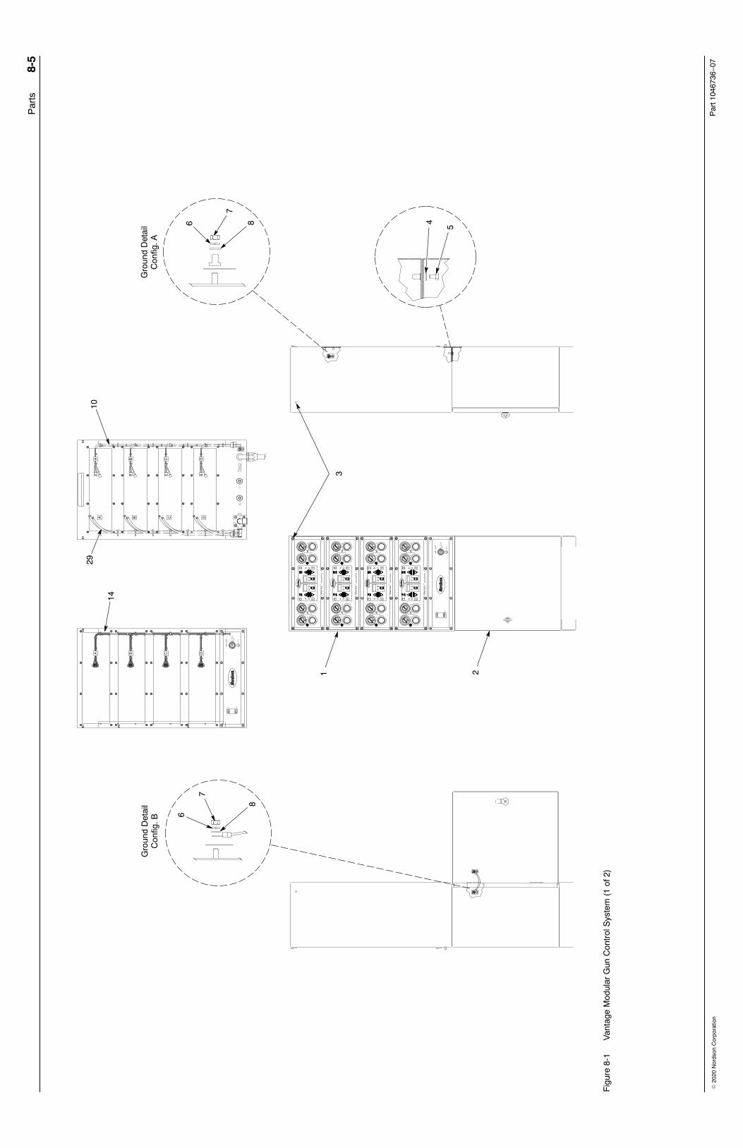
Controller Replacement Parts See Figures 8-1 and 8-2.
Item Part Description Quantity Note1 - - - - - - ENCLOSURE, controller, Vantage, auto 12 - - - - - - CABINET , base, Vantage, automatic controller 1 A3 - - - - - - CAP, tapped, hole, 5 mm, nylon 14 983128 LOCK WASHER, M integral, M6, steel 15 982128 SCREW, hex, machine, M6 x 10, zinc 16 983401 WASHER, lock, m, split, M5, steel, zinc 17 984702 NUT, hex, M5, brass 18 983021 WASHER, flat, e, 0.203 x 0.406 x 0.040 in., brass 19 - - - - - - PANEL, front controller, master controller, Vantage
auto1
10 - - - - - - HARNESS, power distribution, Vantage auto 111 - - - - - - HARNESS, power, switch to terminal breaker,
Vantage, auto1
12 - - - - - - HARNESS, power jumper group, Vantage, auto 113 1050185 CONTROL RELAY, 120 Vac, open, fixed, spot 1NS 939683 � FUSE, 6.3 amps 214 - - - - - - HARNESS, trigger distribution, Vantage auto 115 - - - - - - HARNESS, bypass/lockout, Vantage, auto 116 - - - - - - GASKET, master front panel, Vantage, auto 117 322404 SWITCH, rocker, DPST, dust-tight 118 1000594 SWITCH, keylock, 3−position 1
NOTE A: Used with controller assembly, parts 1043879, 1043877, and 1043901.
Continued...

Parts 8-3
Part 1046736−07� 2020 Nordson Corporation
Item Part Description Quantity Note19 1000595 CONTACT BLOCK, 1-N.O. 7 1-N.C. contact 120 984715 NUT, hex, M4, steel, zinc 121 983403 LOCK WASHER, M split, M4, steel, zinc 122 334805 FILTER, line, RFI, power, 10 A 123 972930 PLUG, pushin, 8mm T, plastic 124 972808 CONNECTORS, strain relief, 1/2-in. NPT 125 984192 NUT lock, 1/2-in NPT, nylon 126 1045837 SCREW, pan, recess, M5x12, with integral lock
washer1
27 972143 CONNECTOR, male, elbow, 16-mm tube x1/2-universal
1
28 - - - - - - GASKET, manifold pneumatic, input 129 900619 TUBE, polyurethane, 8-mm OD, black per ft30 - - - - - - PANEL, front, controller, assembly, Vantage, auto 1
31 1023877 � PCA, dual gun driver, iControl 1
32 1043857 � AIR GAGE, 0−100 psi, 0−7 bar, kpa, 1 1/2 in. 1
33 1045838 � GASKET, gage, diameter 0.41 mm, EDPM 1
34 973572 � COUPLING, pipe, hydraulic, 1/8 in. steel 1
35 972840 � CONNECTOR, male, run tee, 6-mm tube x1/8-in. universal
1
36 1100310 � REGULATOR, 1/4 in. NPT, 7−125 psi 1
37 141603 � SEAL, panel, regulator 1
38 972142 � CONNECTOR, male, elbow, 6-mm tube x1/4-in. universal
1
39 1042142 � PCA, Vantage, interface 140 - - - - - - PANEL, rear, controller assembly, Vantage auto 1
41 1045839 � VALVE, check, adapter, 6-mm tube x 6-mmtube
1
42 971100 � CONNECTOR, male, 6-mm tube x 1/4-in.universal
1
43 - - - - - - � MANIFOLD, pneumatic 1
44 972282 � CONNECTOR, male with internal hex, 8-mmtube x 1/4-in universal
1
45 900742 � TUBING, polyurethane, 6/4 mm, blue 1
46 1043906 � POWER SUPPLY, 24, 5, 12 Vdc, 60 Watt 1
47 1043872 � VALVE, 3 port, direct acting, 24 V, 1/8-in. RPT,with connector
1
48 334818 LABELS, numbers, repeat, 1−16 149 1047751 KIT, keypad with front panel, Vantage 1

Parts8-4
Part 1046736−07 � 2020 Nordson Corporation
Spray Gun Cables Part Description Note
1043723 VERSA-SPRAY CABLE, 100kV, 12M, Vantage, automatic1054175 VERSA-SPRAY CABLE, 100 kV, 16M, Vantage, automatic1048653 SURE COAT CABLE, 12M, Vantage, automatic1054176 SURE COAT CABLE, 16M, Vantage, automatic1054613 ADAPTER, Tribomatic, Vantage, automatic1054615 CONNECTOR, Versa-Spray adapter, Vantage, automatic A
NOTE A: Use this connector with older style Versa-Spray II cables.
Controller Upgrade Kit See Figure 8-2. Order this kit to upgrade your controller assemble from 4−6or 6−8 control units.
Item Part Description Quantity Note— 1043902 CONTROLLER UPGRADE KIT, 2 gun Vantage,
automatic1
29 900619 � TUBE, polyurethane, 8-mm OD, black 4 ft30 - - - - - - � PANEL, front, controller, assembly, Vantage,
auto1
40 - - - - - - � PANEL, rear, controller assembly, Vantage auto 148 334818 � LABELS, numbers, repeat, 1−16 1
Accessories Item Part Description Quantity NoteNS 900600 TUBING nylon, soft, 16-mm OD, black 1 ft ANS 1051108 CONNECTOR, male, 16-mm tube x
1/2-in. universal1
NS 288822 CONNECTOR, orifice, 4-mm x 1/2-in. universal,diameter 0.012 in.
1 B
NOTE A: Main air supply tubing. 20 feet of tubing used in each system.
B: Connecter used with Sure Coat spray guns.
NS: Not Shown
Par
ts8-
5
Par
t 104
6736−
07�
202
0 N
ords
on C
orpo
ratio
n
Gro
und
Det
ail
Con
fig. A
Gro
und
Det
ail
Con
fig. B
6
7
8
1 2
3
5
48
7
6
2910
14
Fig
ure
8-1
Van
tage
Mod
ular
Gun
Con
trol
Sys
tem
(1
of 2
)

Par
ts8-
6
Par
t 104
6736−
07�
202
0 N
ords
on C
orpo
ratio
n
27
26
4848
1110 16
13 6
19
15
28
12
23
25
7 8
40
26
26
30
17
2618
9
20
22 2141
4342
44
45
40
46
47
3637
3638 38
3534
3232
3332
31
39
RE
AR
PA
NE
LF
RO
NT
PA
NE
L
49
Fig
ure
8-2
Van
tage
Mod
ular
Gun
Con
trol
Sys
tem
(2
of 2
)