10.4 Flanged Connections acc. to ASME B16.5 ASME B16.34 - LESER
30
10 Connections LWN 758.00 edition: 30.06.2010 10.4-1 10.4 Flanged Connections acc. to ASME B16.5 / ASME B16.34 Within the ASME Code there are several standards covering pressure-temperature ratings: Standard Title Applies to: ASME B16.5 Pipe Flanges and Flanged Fittings: NPS 1/2 through 24 Steel flanges ASME B16.34 Valves Flanged, Threaded and Welding End Steel valve bodies ASME B16.42 Ductile Iron Pipe Flanges and Flanged Fittings: Classes 150 and 300 Ductile iron flanges Table 10.4-1: ASME code standards covering pressure-temperature ratings ASME B16.5 and ASME B16.34 contain material groups and pressure/temperature ratings which are identical. ASME B16.34 however contains some more materials than ASME B16.5. ASME B16.34 does not list the flange class 400, however it contains a class 4500 which applies to butt weld ends only. Only ASME B16.5 contains flange dimensions. Therefore all tables and chapters in this Engineering Handbook are based on ASME B16.5 (edition 2009) Flanges and pressure-temperature ratings for ductile iron flanges are listed in ASME B16.42 (edition 1998). Pressure/Temperature Ratings acc. to ASME B16.5: Pressure-temperature ratings are maximum allowable working gage pressures at the temperatures shown in the following tables for the applicable material and class designation. For intermediate temperatures, linear interpolation is permitted. Interpolation between class designations is not permitted.
Transcript of 10.4 Flanged Connections acc. to ASME B16.5 ASME B16.34 - LESER
1100 CCoonnnneeccttiioonnss
LWN 758.00 edition: 30.06.2010 10.4-1
10.4 Flanged Connections acc. to ASME B16.5 / ASME B16.34
Within the ASME Code there are several standards covering pressure-temperature ratings: Standard Title Applies to: ASME B16.5 Pipe Flanges and Flanged Fittings: NPS 1/2
through 24 Steel flanges
ASME B16.34 Valves Flanged, Threaded and Welding End Steel valve bodies ASME B16.42 Ductile Iron Pipe Flanges and Flanged
Fittings: Classes 150 and 300 Ductile iron flanges
Table 10.4-1: ASME code standards covering pressure-temperature ratings
ASME B16.5 and ASME B16.34 contain material groups and pressure/temperature ratings which are identical. ASME B16.34 however contains some more materials than ASME B16.5. ASME B16.34 does not list the flange class 400, however it contains a class 4500 which applies to butt weld ends only. Only ASME B16.5 contains flange dimensions. Therefore all tables and chapters in this Engineering Handbook are based on ASME B16.5 (edition 2009) Flanges and pressure-temperature ratings for ductile iron flanges are listed in ASME B16.42 (edition 1998).
Pressure/Temperature Ratings acc. to ASME B16.5:
Pressure-temperature ratings are maximum allowable working gage pressures at the temperatures shown in the following tables for the applicable material and class designation. For intermediate temperatures, linear interpolation is permitted. Interpolation between class designations is not permitted.
1100 CCoonnnneeccttiioonnss
LWN 758.00 edition: 30.06.2010 10.4-2
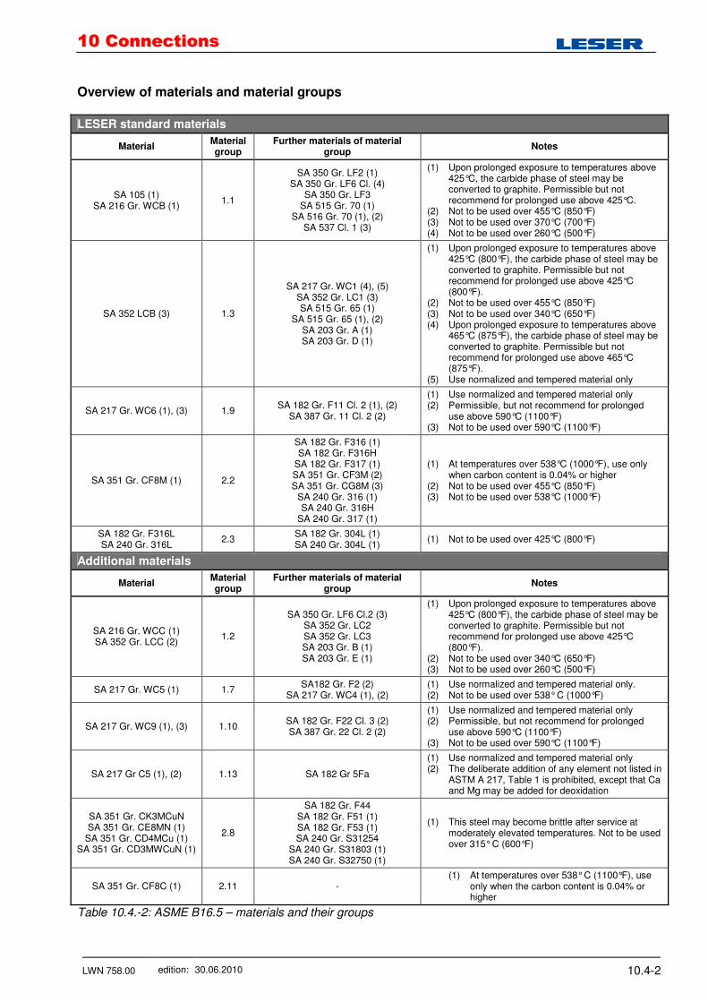
Overview of materials and material groups
LESER standard materials
Material Material group
Further materials of material group
Notes
SA 105 (1) SA 216 Gr. WCB (1)
1.1
SA 350 Gr. LF2 (1) SA 350 Gr. LF6 Cl. (4)
SA 350 Gr. LF3 SA 515 Gr. 70 (1)
SA 516 Gr. 70 (1), (2) SA 537 Cl. 1 (3)
(1) Upon prolonged exposure to temperatures above 425°C, the carbide phase of steel may be converted to graphite. Permissible but not recommend for prolonged use above 425°C.
(2) Not to be used over 455°C (850°F) (3) Not to be used over 370°C (700°F) (4) Not to be used over 260°C (500°F)
SA 352 LCB (3) 1.3
SA 217 Gr. WC1 (4), (5) SA 352 Gr. LC1 (3) SA 515 Gr. 65 (1)
SA 515 Gr. 65 (1), (2) SA 203 Gr. A (1) SA 203 Gr. D (1)
(1) Upon prolonged exposure to temperatures above 425°C (800°F), the carbide phase of steel may be converted to graphite. Permissible but not recommend for prolonged use above 425°C (800°F).
(2) Not to be used over 455°C (850°F) (3) Not to be used over 340°C (650°F) (4) Upon prolonged exposure to temperatures above
465°C (875°F), the carbide phase of steel may be converted to graphite. Permissible but not recommend for prolonged use above 465°C (875°F).
(5) Use normalized and tempered material only
SA 217 Gr. WC6 (1), (3) 1.9 SA 182 Gr. F11 Cl. 2 (1), (2)
SA 387 Gr. 11 Cl. 2 (2)
(1) Use normalized and tempered material only (2) Permissible, but not recommend for prolonged
use above 590°C (1100°F) (3) Not to be used over 590°C (1100°F)
SA 351 Gr. CF8M (1) 2.2
SA 182 Gr. F316 (1) SA 182 Gr. F316H
SA 182 Gr. F317 (1) SA 351 Gr. CF3M (2) SA 351 Gr. CG8M (3)
SA 240 Gr. 316 (1) SA 240 Gr. 316H
SA 240 Gr. 317 (1)
(1) At temperatures over 538°C (1000°F), use only when carbon content is 0.04% or higher
(2) Not to be used over 455°C (850°F) (3) Not to be used over 538°C (1000°F)
SA 182 Gr. F316L SA 240 Gr. 316L
2.3 SA 182 Gr. 304L (1) SA 240 Gr. 304L (1)
(1) Not to be used over 425°C (800°F)
Additional materials
Material Material group
Further materials of material group
Notes
SA 216 Gr. WCC (1) SA 352 Gr. LCC (2)
1.2
SA 350 Gr. LF6 Cl.2 (3) SA 352 Gr. LC2 SA 352 Gr. LC3 SA 203 Gr. B (1) SA 203 Gr. E (1)
(1) Upon prolonged exposure to temperatures above 425°C (800°F), the carbide phase of steel may be converted to graphite. Permissible but not recommend for prolonged use above 425°C (800°F).
(2) Not to be used over 340°C (650°F) (3) Not to be used over 260°C (500°F)
SA 217 Gr. WC5 (1) 1.7 SA182 Gr. F2 (2)
SA 217 Gr. WC4 (1), (2) (1) Use normalized and tempered material only. (2) Not to be used over 538° C (1000°F)
SA 217 Gr. WC9 (1), (3) 1.10 SA 182 Gr. F22 Cl. 3 (2) SA 387 Gr. 22 Cl. 2 (2)
(1) Use normalized and tempered material only (2) Permissible, but not recommend for prolonged
use above 590°C (1100°F) (3) Not to be used over 590°C (1100°F)
SA 217 Gr C5 (1), (2) 1.13 SA 182 Gr 5Fa
(1) Use normalized and tempered material only (2) The deliberate addition of any element not listed in
ASTM A 217, Table 1 is prohibited, except that Ca and Mg may be added for deoxidation
SA 351 Gr. CK3MCuN SA 351 Gr. CE8MN (1)
SA 351 Gr. CD4MCu (1) SA 351 Gr. CD3MWCuN (1)
2.8
SA 182 Gr. F44 SA 182 Gr. F51 (1) SA 182 Gr. F53 (1) SA 240 Gr. S31254
SA 240 Gr. S31803 (1) SA 240 Gr. S32750 (1)
(1) This steel may become brittle after service at moderately elevated temperatures. Not to be used over 315° C (600°F)
SA 351 Gr. CF8C (1) 2.11 - (1) At temperatures over 538° C (1100°F), use
only when the carbon content is 0.04% or higher
Table 10.4.-2: ASME B16.5 – materials and their groups
1100 CCoonnnneeccttiioonnss
LWN 758.00 edition: 30.06.2010 10.4-3
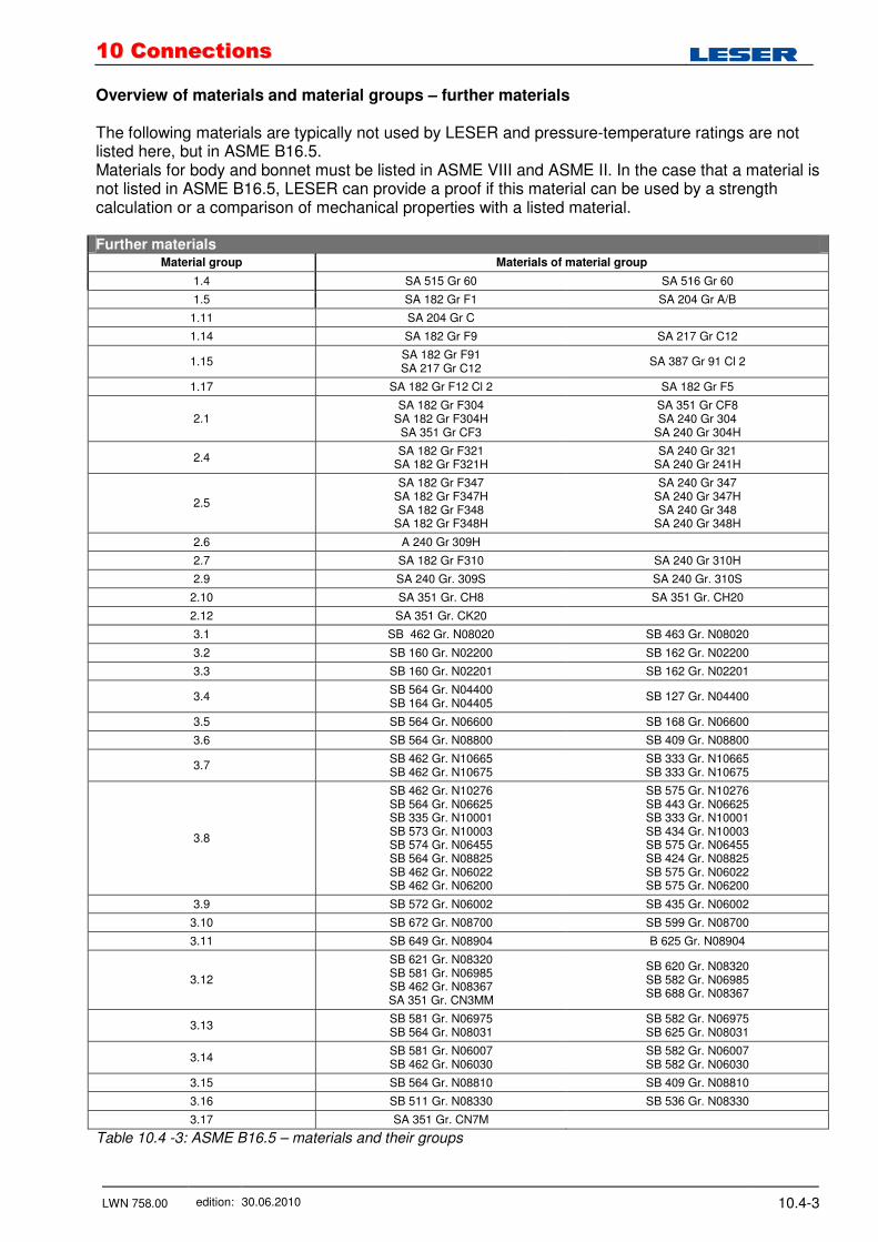
Overview of materials and material groups – further materials The following materials are typically not used by LESER and pressure-temperature ratings are not listed here, but in ASME B16.5. Materials for body and bonnet must be listed in ASME VIII and ASME II. In the case that a material is not listed in ASME B16.5, LESER can provide a proof if this material can be used by a strength calculation or a comparison of mechanical properties with a listed material. Further materials
Material group Materials of material group
1.4 SA 515 Gr 60 SA 516 Gr 60
1.5 SA 182 Gr F1 SA 204 Gr A/B
1.11 SA 204 Gr C
1.14 SA 182 Gr F9 SA 217 Gr C12
1.15 SA 182 Gr F91 SA 217 Gr C12
SA 387 Gr 91 Cl 2
1.17 SA 182 Gr F12 Cl 2 SA 182 Gr F5
2.1 SA 182 Gr F304
SA 182 Gr F304H SA 351 Gr CF3
SA 351 Gr CF8 SA 240 Gr 304
SA 240 Gr 304H
2.4 SA 182 Gr F321
SA 182 Gr F321H SA 240 Gr 321
SA 240 Gr 241H
2.5
SA 182 Gr F347 SA 182 Gr F347H SA 182 Gr F348
SA 182 Gr F348H
SA 240 Gr 347 SA 240 Gr 347H SA 240 Gr 348
SA 240 Gr 348H
2.6 A 240 Gr 309H
2.7 SA 182 Gr F310 SA 240 Gr 310H
2.9 SA 240 Gr. 309S SA 240 Gr. 310S
2.10 SA 351 Gr. CH8 SA 351 Gr. CH20
2.12 SA 351 Gr. CK20
3.1 SB 462 Gr. N08020 SB 463 Gr. N08020
3.2 SB 160 Gr. N02200 SB 162 Gr. N02200
3.3 SB 160 Gr. N02201 SB 162 Gr. N02201
3.4 SB 564 Gr. N04400 SB 164 Gr. N04405
SB 127 Gr. N04400
3.5 SB 564 Gr. N06600 SB 168 Gr. N06600
3.6 SB 564 Gr. N08800 SB 409 Gr. N08800
3.7 SB 462 Gr. N10665 SB 462 Gr. N10675
SB 333 Gr. N10665 SB 333 Gr. N10675
3.8
SB 462 Gr. N10276 SB 564 Gr. N06625 SB 335 Gr. N10001 SB 573 Gr. N10003 SB 574 Gr. N06455 SB 564 Gr. N08825 SB 462 Gr. N06022 SB 462 Gr. N06200
SB 575 Gr. N10276 SB 443 Gr. N06625 SB 333 Gr. N10001 SB 434 Gr. N10003 SB 575 Gr. N06455 SB 424 Gr. N08825 SB 575 Gr. N06022 SB 575 Gr. N06200
3.9 SB 572 Gr. N06002 SB 435 Gr. N06002
3.10 SB 672 Gr. N08700 SB 599 Gr. N08700
3.11 SB 649 Gr. N08904 B 625 Gr. N08904
3.12
SB 621 Gr. N08320 SB 581 Gr. N06985 SB 462 Gr. N08367 SA 351 Gr. CN3MM
SB 620 Gr. N08320 SB 582 Gr. N06985 SB 688 Gr. N08367
3.13 SB 581 Gr. N06975 SB 564 Gr. N08031
SB 582 Gr. N06975 SB 625 Gr. N08031
3.14 SB 581 Gr. N06007 SB 462 Gr. N06030
SB 582 Gr. N06007 SB 582 Gr. N06030
3.15 SB 564 Gr. N08810 SB 409 Gr. N08810
3.16 SB 511 Gr. N08330 SB 536 Gr. N08330
3.17 SA 351 Gr. CN7M
Table 10.4 -3: ASME B16.5 – materials and their groups
1100 CCoonnnneeccttiioonnss
LWN 758.00 edition: 30.06.2010 10.4-4
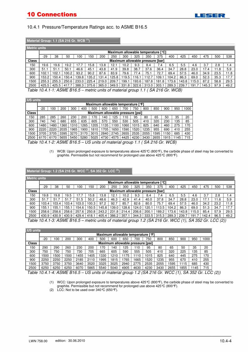
10.4.1 Pressure/Temperature Ratings acc. to ASME B16.5
Material Group: 1.1 (SA 216 Gr. WCB
(1))
Metric units
Maximum allowable temperature [°C]
-29 38 50 100 150 200 250 300 325 350 375 400 425 450 475 500 538
Class Maximum allowable pressure [bar]
150 19.6 19.6 19.2 17.7 15.8 13.8 12.1 10.2 9.3 8.4 7.4 6.5 5.5 4.6 3.7 2.8 1.4 300 51.1 51.1 50.1 46.6 45.1 43.8 41.9 39.8 38.7 37.6 36.4 34.7 28.8 23.0 17.4 11.8 5.9 600 102.1 102.1 100.2 93.2 90.2 87.6 83.9 79.6 77.4 75.1 72.7 69.4 57.5 46.0 34.9 23.5 11.8 900 153.2 150.4 150.4 139.8 135.2 131.4 125.8 119.5 116.1 112.7 109.1 104.2 86.3 69.0 52.3 35.3 17.7
1500 255.3 255.3 250.6 233.0 225.4 219.0 209.7 199.1 193.6 187.8 181.8 173.6 143.8 115.0 87.2 58.8 29.5 2500 425.5 425.5 417.7 388.3 375.6 365.0 349.5 331.8 322.6 313.0 303.1 289.3 239.7 191.7 145.3 97.9 49.2
Table 10.4.1-1: ASME B16.5 – metric units of material group 1.1 ( SA 216 Gr. WCB)
US units
Maximum allowable temperature [°F]
-20 100 200 300 400 500 600 650 700 750 800 850 900 950 1000
Class Maximum allowable pressure [psi]
150 285 285 260 230 200 170 140 125 110 95 80 65 50 35 20 300 740 740 680 655 635 605 570 550 530 505 410 320 230 135 85 600 1480 1480 1360 1310 1265 1205 1135 1100 1060 1015 825 640 460 275 170 900 2220 2220 2035 1965 1900 1810 1705 1650 1590 1520 1235 955 690 410 255 1500 3705 3705 3395 3270 3170 3015 2840 2745 2655 2535 2055 1595 1150 685 430 2500 6170 6170 5655 5450 5280 5025 4730 4575 4425 4230 3430 2655 1915 1145 715
Table 10.4.1-2: ASME B16.5 – US units of material group 1.1 ( SA 216 Gr. WCB)
(1) WCB: Upon prolonged exposure to temperatures above 425°C (800°F), the carbide phase of steel may be converted to graphite. Permissible but not recommend for prolonged use above 425°C (800°F).
Material Group: 1.2 (SA 216 Gr. WCC
(1), SA 352 Gr. LCC
(2))
Metric units
Maximum allowable temperature [°C]
-29 38 50 100 150 200 250 300 325 350 375 400 425 450 475 500 538
Class Maximum allowable pressure [bar]
150 19.8 19.8 19.5 17.7 15.8 13.8 12.1 10.2 9.3 8.4 7.4 6.5 5.5 4.6 3.7 2.8 1.4 300 51.7 51.7 51.7 51.5 50.2 48.6 46.3 42.9 41.4 40.0 37.8 34.7 28.8 23.0 17.1 11.6 5.9 600 103.4 103.4 103.4 103.0 100.3 97.2 92.7 85.7 82.6 80.0 75.7 69.4 57.5 46.0 34.2 23.2 11.8 900 155.1 155.1 155.1 154.6 150.5 145.8 139.0 128.6 124.0 120.1 113.5 104.2 86.3 69.0 51.3 34.7 17.7
1500 258.6 258.6 258.6 257.6 250.8 243.2 231.8 214.4 206.6 200.1 189.2 173.6 143.8 115.0 85.4 57.9 29.5 2500 430.9 430.9 430.9 429.4 418.1 405.4 386.2 357.1 344.3 333.5 315.3 289.3 239.7 191.7 142.4 96.5 49.2
Table 10.4.1-3: ASME B16.5 – metric units of material group 1.2 (SA 216 Gr. WCC (1), SA 352 Gr. LCC (2))
US units
Maximum allowable temperature [°F]
-20 100 200 300 400 500 600 650 700 750 800 850 900 950 1000
Class Maximum allowable pressure [psi]
150 290 290 260 230 200 170 140 125 110 95 80 65 50 35 20 300 750 750 750 730 705 665 605 590 555 505 410 320 225 135 85 600 1500 1500 1500 1455 1405 1330 1210 1175 1110 1015 825 640 445 275 170 900 2250 2250 2250 2185 2110 1995 1815 1765 1665 1520 1235 955 670 410 255
1500 3750 3750 3750 3640 3520 3325 3025 2940 2775 2535 2055 1595 1115 685 430 2500 6250 6250 6250 6070 5865 5540 5040 4905 4630 4230 3430 2655 1855 1145 715
Table 10.4.1-4: ASME B16.5 – US units of material group 1.2 (SA 216 Gr. WCC (1), SA 352 Gr. LCC (2))
(1) WCC: Upon prolonged exposure to temperatures above 425°C (800°F), the carbide phase of steel may be converted to
graphite. Permissible but not recommend for prolonged use above 425°C (800°F). (2) LCC: Not to be used over 340°C (650°F).
1100 CCoonnnneeccttiioonnss
LWN 758.00 edition: 30.06.2010 10.4-5
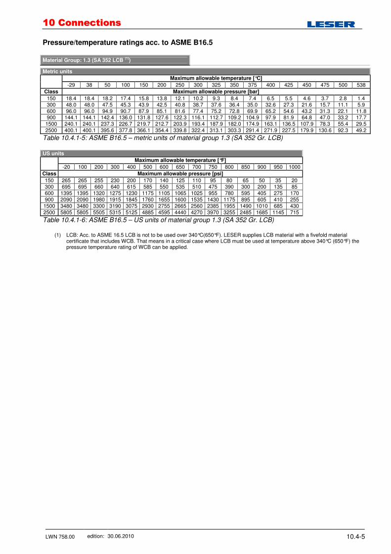
Pressure/temperature ratings acc. to ASME B16.5 Material Group: 1.3 (SA 352 LCB
(1))
Metric units
Maximum allowable temperature [°C]
-29 38 50 100 150 200 250 300 325 350 375 400 425 450 475 500 538
Class Maximum allowable pressure [bar]
150 18.4 18.4 18.2 17.4 15.8 13.8 12.1 10.2 9.3 8.4 7.4 6.5 5.5 4.6 3.7 2.8 1.4 300 48.0 48.0 47.5 45.3 43.9 42.5 40.8 38.7 37.6 36.4 35.0 32.6 27.3 21.6 15.7 11.1 5.9 600 96.0 96.0 94.9 90.7 87.9 85.1 81.6 77.4 75.2 72.8 69.9 65.2 54.6 43.2 31.3 22.1 11.8 900 144.1 144.1 142.4 136.0 131.8 127.6 122.3 116.1 112.7 109.2 104.9 97.9 81.9 64.8 47.0 33.2 17.7
1500 240.1 240.1 237.3 226.7 219.7 212.7 203.9 193.4 187.9 182.0 174.9 163.1 136.5 107.9 78.3 55.4 29.5 2500 400.1 400.1 395.6 377.8 366.1 354.4 339.8 322.4 313.1 303.3 291.4 271.9 227.5 179.9 130.6 92.3 49.2
Table 10.4.1-5: ASME B16.5 – metric units of material group 1.3 (SA 352 Gr. LCB)
US units
Maximum allowable temperature [°F]
-20 100 200 300 400 500 600 650 700 750 800 850 900 950 1000
Class Maximum allowable pressure [psi]
150 265 265 255 230 200 170 140 125 110 95 80 65 50 35 20 300 695 695 660 640 615 585 550 535 510 475 390 300 200 135 85 600 1395 1395 1320 1275 1230 1175 1105 1065 1025 955 780 595 405 275 170 900 2090 2090 1980 1915 1845 1760 1655 1600 1535 1430 1175 895 605 410 255
1500 3480 3480 3300 3190 3075 2930 2755 2665 2560 2385 1955 1490 1010 685 430 2500 5805 5805 5505 5315 5125 4885 4595 4440 4270 3970 3255 2485 1685 1145 715
Table 10.4.1-6: ASME B16.5 – US units of material group 1.3 (SA 352 Gr. LCB)
(1) LCB: Acc. to ASME 16.5 LCB is not to be used over 340°C(650°F). LESER supplies LCB material with a fivefold material
certificate that includes WCB. That means in a critical case where LCB must be used at temperature above 340°C (650°F) the pressure temperature rating of WCB can be applied.

1100 CCoonnnneeccttiioonnss
LWN 758.00 edition: 30.06.2010 10.4-6
Pressure/temperature ratings acc. to ASME B16.5 Material Group: 1.7 (SA 217 Gr. WC5)
Metric units
Maximum allowable temperature [°C]
-29 38 50 100 150 200 250 300 325 350
Class Maximum allowable pressure [bar]
150 19.8 19.8 19.5 17.7 15.8 13.8 12.1 10.2 9.3 8.4 300 51.7 51.7 51.7 51.5 50.3 48.6 46.3 42.9 41.4 40.3 600 103.4 103.4 103.4 103.0 100.3 97.2 92.7 85.7 82.6 80.4 900 155.1 155.1 155.1 154.6 150.6 145.8 139.0 128.6 124.0 120.7 1500 258.6 258.6 258.6 257.6 250.8 243.4 231.8 214.4 206.6 201.1 2500 430.9 430.9 430.9 429.4 418.2 405.4 386.2 357.1 344.3 335.3
Table 10.4.1-7: ASME B16.5 – metric units of material group 1.7 (SA 217 Gr. WC5)
Metric units
Maximum allowable temperature [°C]
375 400 425 450 475 500 538 550 575
Class Maximum allowable pressure [bar]
150 7.4 6.5 5.5 4.6 3.7 2.8 1.4 - - 300 38.9 36.5 35.2 33.7 31.7 26.7 13.9 12.6 7.2 600 77.6 73.3 70.0 67.7 63.4 53.4 27.9 25.2 14.4 900 116.5 109.8 105.1 101.4 95.1 80.1 41.8 37.8 21.5
1500 194.1 183.1 175.1 169.0 158.2 133.4 69.7 63.0 35.9 2500 323.2 304.9 291.6 281.8 263.9 222.4 116.2 105.0 59.8
Table 10.4.1-8: ASME B16.5 – metric units of material group 1.7 (SA 217 Gr. WC5)
US units
Maximum allowable temperature [°F]
-20 100 200 300 400 500 600 650 700 750
Class Maximum allowable pressure [psi]
150 290 290 260 230 200 170 140 125 110 95 300 750 750 750 730 705 665 605 590 570 530 600 1500 1500 1500 1455 1410 1330 1210 1175 1135 1065 900 2250 2250 2250 2185 2115 1995 1815 1765 1705 1595 1500 3750 3750 3750 3640 3530 3325 3025 2940 2840 2660 2500 6250 6250 6250 6070 5880 5540 5040 4905 4730 4430
Table 10.4.1-9 : ASME B16.5 – US units of material group 1.7 (SA 217 Gr. WC5)
US units
Maximum allowable temperature [°F]
800 850 900 950 1000 1050
Class Maximum allowable pressure [psi]
150 80 65 50 35 20 - 300 510 485 450 315 200 160 600 1015 975 900 630 405 315 900 1525 1460 1350 945 605 475
1500 2540 2435 2245 1575 1010 790 2500 4230 4060 3745 2630 1685 1315
Table 10.4.1-10: ASME B16.5 – US units of material group 1.7 (SA 217 Gr. WC5)
1100 CCoonnnneeccttiioonnss
LWN 758.00 edition: 30.06.2010 10.4-7
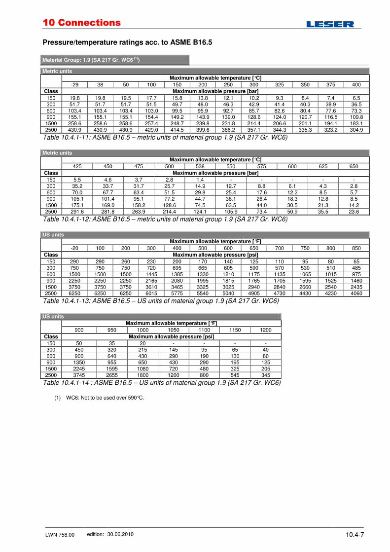
Pressure/temperature ratings acc. to ASME B16.5 Material Group: 1.9 (SA 217 Gr. WC6
(1))
Metric units
Maximum allowable temperature [°C]
-29 38 50 100 150 200 250 300 325 350 375 400
Class Maximum allowable pressure [bar]
150 19.8 19.8 19.5 17.7 15.8 13.8 12.1 10.2 9.3 8.4 7.4 6.5 300 51.7 51.7 51.7 51.5 49.7 48.0 46.3 42.9 41.4 40.3 38.9 36.5 600 103.4 103.4 103.4 103.0 99.5 95.9 92.7 85.7 82.6 80.4 77.6 73.3 900 155.1 155.1 155.1 154.4 149.2 143.9 139.0 128.6 124.0 120.7 116.5 109.8 1500 258.6 258.6 258.6 257.4 248.7 239.8 231.8 214.4 206.6 201.1 194.1 183.1 2500 430.9 430.9 430.9 429.0 414.5 399.6 386.2 357.1 344.3 335.3 323.2 304.9
Table 10.4.1-11: ASME B16.5 – metric units of material group 1.9 (SA 217 Gr. WC6)
Metric units
Maximum allowable temperature [°C]
425 450 475 500 538 550 575 600 625 650
Class Maximum allowable pressure [bar]
150 5.5 4.6 3.7 2.8 1.4 - - - - - 300 35.2 33.7 31.7 25.7 14.9 12.7 8.8 6.1 4.3 2.8 600 70.0 67.7 63.4 51.5 29.8 25.4 17.6 12.2 8.5 5.7 900 105.1 101.4 95.1 77.2 44.7 38.1 26.4 18.3 12.8 8.5 1500 175.1 169.0 158.2 128.6 74.5 63.5 44.0 30.5 21.3 14.2 2500 291.6 281.8 263.9 214.4 124.1 105.9 73.4 50.9 35.5 23.6
Table 10.4.1-12: ASME B16.5 – metric units of material group 1.9 (SA 217 Gr. WC6)
US units
Maximum allowable temperature [°F]
-20 100 200 300 400 500 600 650 700 750 800 850
Class Maximum allowable pressure [psi]
150 290 290 260 230 200 170 140 125 110 95 80 65 300 750 750 750 720 695 665 605 590 570 530 510 485 600 1500 1500 1500 1445 1385 1330 1210 1175 1135 1065 1015 975 900 2250 2250 2250 2165 2080 1995 1815 1765 1705 1595 1525 1460
1500 3750 3750 3750 3610 3465 3325 3025 2940 2840 2660 2540 2435 2500 6250 6250 6250 6015 5775 5540 5040 4905 4730 4430 4230 4060
Table 10.4.1-13: ASME B16.5 – US units of material group 1.9 (SA 217 Gr. WC6)
US units
Maximum allowable temperature [°F]
900 950 1000 1050 1100 1150 1200
Class Maximum allowable pressure [psi]
150 50 35 20 - - - - 300 450 320 215 145 95 65 40 600 900 640 430 290 190 130 80 900 1350 955 650 430 290 195 125 1500 2245 1595 1080 720 480 325 205 2500 3745 2655 1800 1200 800 545 345
Table 10.4.1-14 : ASME B16.5 – US units of material group 1.9 (SA 217 Gr. WC6)
(1) WC6: Not to be used over 590°C.
1100 CCoonnnneeccttiioonnss
LWN 758.00 edition: 30.06.2010 10.4-8
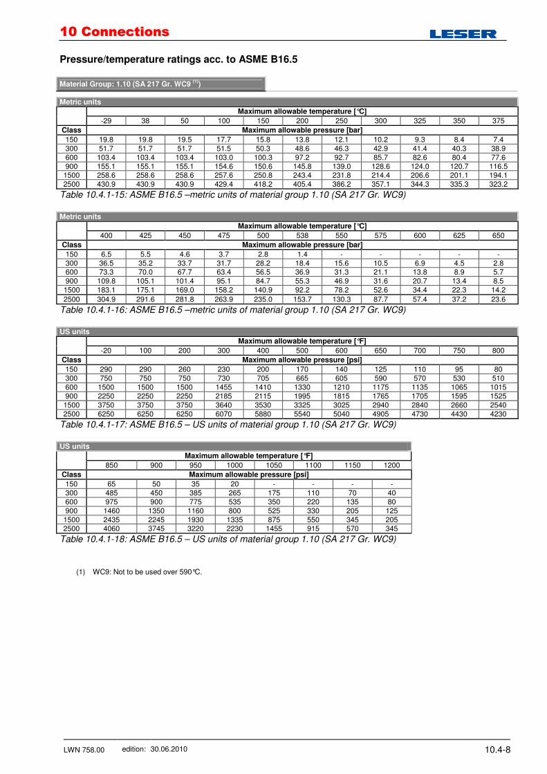
Pressure/temperature ratings acc. to ASME B16.5 Material Group: 1.10 (SA 217 Gr. WC9
(1))
Metric units
Maximum allowable temperature [°C]
-29 38 50 100 150 200 250 300 325 350 375
Class Maximum allowable pressure [bar]
150 19.8 19.8 19.5 17.7 15.8 13.8 12.1 10.2 9.3 8.4 7.4 300 51.7 51.7 51.7 51.5 50.3 48.6 46.3 42.9 41.4 40.3 38.9 600 103.4 103.4 103.4 103.0 100.3 97.2 92.7 85.7 82.6 80.4 77.6 900 155.1 155.1 155.1 154.6 150.6 145.8 139.0 128.6 124.0 120.7 116.5
1500 258.6 258.6 258.6 257.6 250.8 243.4 231.8 214.4 206.6 201.1 194.1 2500 430.9 430.9 430.9 429.4 418.2 405.4 386.2 357.1 344.3 335.3 323.2
Table 10.4.1-15: ASME B16.5 –metric units of material group 1.10 (SA 217 Gr. WC9)
Metric units
Maximum allowable temperature [°C]
400 425 450 475 500 538 550 575 600 625 650
Class Maximum allowable pressure [bar]
150 6.5 5.5 4.6 3.7 2.8 1.4 - - - - - 300 36.5 35.2 33.7 31.7 28.2 18.4 15.6 10.5 6.9 4.5 2.8 600 73.3 70.0 67.7 63.4 56.5 36.9 31.3 21.1 13.8 8.9 5.7 900 109.8 105.1 101.4 95.1 84.7 55.3 46.9 31.6 20.7 13.4 8.5 1500 183.1 175.1 169.0 158.2 140.9 92.2 78.2 52.6 34.4 22.3 14.2
2500 304.9 291.6 281.8 263.9 235.0 153.7 130.3 87.7 57.4 37.2 23.6
Table 10.4.1-16: ASME B16.5 –metric units of material group 1.10 (SA 217 Gr. WC9)
US units
Maximum allowable temperature [°F]
-20 100 200 300 400 500 600 650 700 750 800
Class Maximum allowable pressure [psi]
150 290 290 260 230 200 170 140 125 110 95 80 300 750 750 750 730 705 665 605 590 570 530 510 600 1500 1500 1500 1455 1410 1330 1210 1175 1135 1065 1015 900 2250 2250 2250 2185 2115 1995 1815 1765 1705 1595 1525 1500 3750 3750 3750 3640 3530 3325 3025 2940 2840 2660 2540 2500 6250 6250 6250 6070 5880 5540 5040 4905 4730 4430 4230
Table 10.4.1-17: ASME B16.5 – US units of material group 1.10 (SA 217 Gr. WC9)
US units
Maximum allowable temperature [°F]
850 900 950 1000 1050 1100 1150 1200
Class Maximum allowable pressure [psi]
150 65 50 35 20 - - - - 300 485 450 385 265 175 110 70 40 600 975 900 775 535 350 220 135 80 900 1460 1350 1160 800 525 330 205 125 1500 2435 2245 1930 1335 875 550 345 205 2500 4060 3745 3220 2230 1455 915 570 345
Table 10.4.1-18: ASME B16.5 – US units of material group 1.10 (SA 217 Gr. WC9)
(1) WC9: Not to be used over 590°C.

1100 CCoonnnneeccttiioonnss
LWN 758.00 edition: 30.06.2010 10.4-9
Pressure/temperature ratings acc. to ASME B16.5 Material Group: 1.13 (A 217 Gr. C5)
Metric units
Maximum allowable temperature [°C]
-29 38 50 100 150 200 250 300 325 350 375
Class Maximum allowable pressure [bar]
150 20.0 20.0 19.5 17.7 15.8 13.8 12.1 10.2 9.3 8.4 7.4 300 51.7 51.7 51.7 51.5 50.3 48.6 46.3 42.9 41.4 40.3 38.9 600 103.4 103.4 103.4 103.0 100.3 97.2 92.7 85.7 82.6 80.4 77.6 900 155.1 155.1 155.1 154.6 150.6 145.8 139.0 128.6 124.0 120.7 116.5
1500 258.6 258.6 258.6 257.6 250.8 243.4 231.8 214.4 206.6 201.1 194.1 2500 430.9 430.9 430.9 429.4 418.2 405.4 386.2 357.1 344.3 335.3 323.2
Table 10.4.1-19: ASME B16.5 –metric units of material group 1.13 (A 217 Gr. C5)
Metric units
Maximum allowable temperature [°C]
400 425 450 475 500 538 550 575 600 625 650
Class Maximum allowable pressure [bar]
150 6.5 5.5 4.6 3.7 2.8 1.4 - - - - - 300 36.5 35.2 33.7 27.9 21.4 13.7 12.0 8.9 6.2 4.0 2.4 600 73.3 70.0 67.7 55.7 42.8 27.4 24.1 17.8 12.5 8.0 4.7 900 109.8 105.1 101.4 83.6 64.1 41.1 36.1 26.7 18.7 12.0 7.1 1500 183.1 175.1 169.0 139.3 106.9 68.6 60.2 44.4 31.2 20.0 11.8
2500 304.9 291.6 281.8 232.1 178.2 114.3 100.4 74.0 51.9 33.3 19.7
Table 10.4.1-20: ASME B16.5 –metric units of material group 1.13 (A 217 Gr. C5)
US units
Maximum allowable temperature [°F]
-20 100 200 300 400 500 600 650 700 750 800
Class Maximum allowable pressure [psi]
150 290 290 260 230 200 170 140 125 110 95 80 300 750 750 750 730 705 665 605 590 570 530 510 600 1500 1500 1500 1455 1410 1330 1210 1175 1135 1065 1015 900 2250 2250 2250 2185 2115 1995 1815 1765 1705 1595 1525 1500 3750 3750 3750 3640 3530 3325 3025 2940 2840 2660 2540 2500 6250 6250 6250 6070 5880 5540 5040 4905 4730 4430 4230
Table 10.4.1-21: ASME B16.5 – US units of material group 1.13 (A 217 Gr. C5)
US units
Maximum allowable temperature [°F]
850 900 950 1000 1050 1100 1150 1200
Class Maximum allowable pressure [psi]
150 65 50 35 20 - - - - 300 485 375 275 200 145 100 60 35 600 975 745 550 400 290 200 125 70 900 1460 1120 825 595 430 300 185 105 1500 2435 1870 1370 995 720 495 310 170 2500 4060 3115 2285 1655 1200 830 515 285
Table 10.4.1-22: ASME B16.5 – US units of material group 1.13 (A 217 Gr. C5)
1100 CCoonnnneeccttiioonnss
LWN 758.00 edition: 30.06.2010 10.4-10
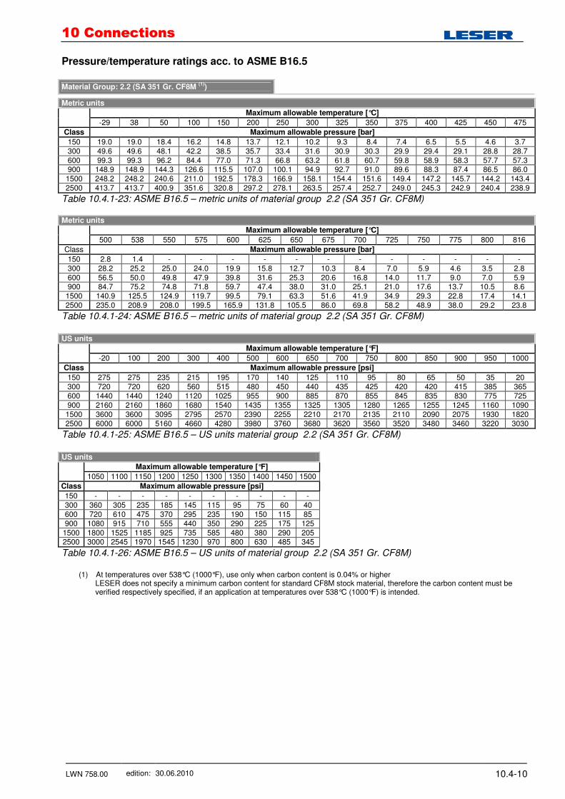
Pressure/temperature ratings acc. to ASME B16.5 Material Group: 2.2 (SA 351 Gr. CF8M
(1))
Metric units
Maximum allowable temperature [°C]
-29 38 50 100 150 200 250 300 325 350 375 400 425 450 475
Class Maximum allowable pressure [bar]
150 19.0 19.0 18.4 16.2 14.8 13.7 12.1 10.2 9.3 8.4 7.4 6.5 5.5 4.6 3.7 300 49.6 49.6 48.1 42.2 38.5 35.7 33.4 31.6 30.9 30.3 29.9 29.4 29.1 28.8 28.7 600 99.3 99.3 96.2 84.4 77.0 71.3 66.8 63.2 61.8 60.7 59.8 58.9 58.3 57.7 57.3 900 148.9 148.9 144.3 126.6 115.5 107.0 100.1 94.9 92.7 91.0 89.6 88.3 87.4 86.5 86.0 1500 248.2 248.2 240.6 211.0 192.5 178.3 166.9 158.1 154.4 151.6 149.4 147.2 145.7 144.2 143.4 2500 413.7 413.7 400.9 351.6 320.8 297.2 278.1 263.5 257.4 252.7 249.0 245.3 242.9 240.4 238.9
Table 10.4.1-23: ASME B16.5 – metric units of material group 2.2 (SA 351 Gr. CF8M) Metric units
Maximum allowable temperature [°C]
500 538 550 575 600 625 650 675 700 725 750 775 800 816
Class Maximum allowable pressure [bar]
150 2.8 1.4 - - - - - - - - - - - - 300 28.2 25.2 25.0 24.0 19.9 15.8 12.7 10.3 8.4 7.0 5.9 4.6 3.5 2.8 600 56.5 50.0 49.8 47.9 39.8 31.6 25.3 20.6 16.8 14.0 11.7 9.0 7.0 5.9 900 84.7 75.2 74.8 71.8 59.7 47.4 38.0 31.0 25.1 21.0 17.6 13.7 10.5 8.6
1500 140.9 125.5 124.9 119.7 99.5 79.1 63.3 51.6 41.9 34.9 29.3 22.8 17.4 14.1 2500 235.0 208.9 208.0 199.5 165.9 131.8 105.5 86.0 69.8 58.2 48.9 38.0 29.2 23.8
Table 10.4.1-24: ASME B16.5 – metric units of material group 2.2 (SA 351 Gr. CF8M)
US units
Maximum allowable temperature [°F]
-20 100 200 300 400 500 600 650 700 750 800 850 900 950 1000
Class Maximum allowable pressure [psi]
150 275 275 235 215 195 170 140 125 110 95 80 65 50 35 20 300 720 720 620 560 515 480 450 440 435 425 420 420 415 385 365 600 1440 1440 1240 1120 1025 955 900 885 870 855 845 835 830 775 725 900 2160 2160 1860 1680 1540 1435 1355 1325 1305 1280 1265 1255 1245 1160 1090 1500 3600 3600 3095 2795 2570 2390 2255 2210 2170 2135 2110 2090 2075 1930 1820 2500 6000 6000 5160 4660 4280 3980 3760 3680 3620 3560 3520 3480 3460 3220 3030
Table 10.4.1-25: ASME B16.5 – US units material group 2.2 (SA 351 Gr. CF8M)
US units
Maximum allowable temperature [°F]
1050 1100 1150 1200 1250 1300 1350 1400 1450 1500
Class Maximum allowable pressure [psi]
150 - - - - - - - - - - 300 360 305 235 185 145 115 95 75 60 40 600 720 610 475 370 295 235 190 150 115 85 900 1080 915 710 555 440 350 290 225 175 125
1500 1800 1525 1185 925 735 585 480 380 290 205 2500 3000 2545 1970 1545 1230 970 800 630 485 345
Table 10.4.1-26: ASME B16.5 – US units of material group 2.2 (SA 351 Gr. CF8M)
(1) At temperatures over 538°C (1000°F), use only when carbon content is 0.04% or higher
LESER does not specify a minimum carbon content for standard CF8M stock material, therefore the carbon content must be verified respectively specified, if an application at temperatures over 538°C (1000°F) is intended.
1100 CCoonnnneeccttiioonnss
LWN 758.00 edition: 30.06.2010 10.4-11
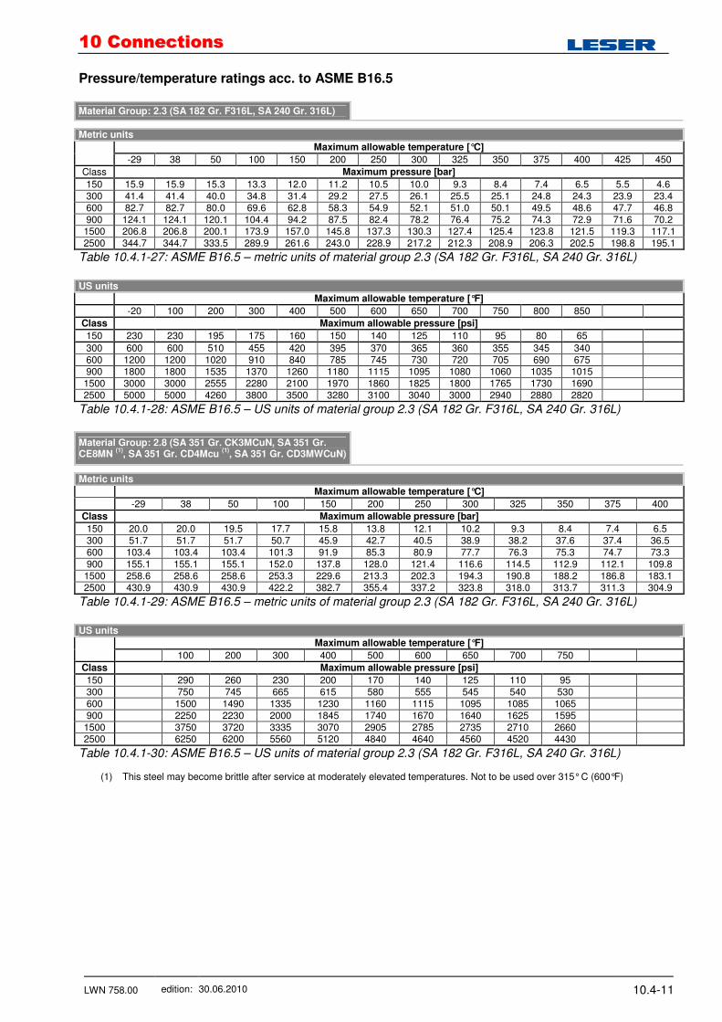
Pressure/temperature ratings acc. to ASME B16.5 Material Group: 2.3 (SA 182 Gr. F316L, SA 240 Gr. 316L)
Metric units
Maximum allowable temperature [°C]
-29 38 50 100 150 200 250 300 325 350 375 400 425 450
Class Maximum pressure [bar]
150 15.9 15.9 15.3 13.3 12.0 11.2 10.5 10.0 9.3 8.4 7.4 6.5 5.5 4.6 300 41.4 41.4 40.0 34.8 31.4 29.2 27.5 26.1 25.5 25.1 24.8 24.3 23.9 23.4 600 82.7 82.7 80.0 69.6 62.8 58.3 54.9 52.1 51.0 50.1 49.5 48.6 47.7 46.8 900 124.1 124.1 120.1 104.4 94.2 87.5 82.4 78.2 76.4 75.2 74.3 72.9 71.6 70.2 1500 206.8 206.8 200.1 173.9 157.0 145.8 137.3 130.3 127.4 125.4 123.8 121.5 119.3 117.1 2500 344.7 344.7 333.5 289.9 261.6 243.0 228.9 217.2 212.3 208.9 206.3 202.5 198.8 195.1
Table 10.4.1-27: ASME B16.5 – metric units of material group 2.3 (SA 182 Gr. F316L, SA 240 Gr. 316L)
US units
Maximum allowable temperature [°F]
-20 100 200 300 400 500 600 650 700 750 800 850
Class Maximum allowable pressure [psi]
150 230 230 195 175 160 150 140 125 110 95 80 65
300 600 600 510 455 420 395 370 365 360 355 345 340 600 1200 1200 1020 910 840 785 745 730 720 705 690 675 900 1800 1800 1535 1370 1260 1180 1115 1095 1080 1060 1035 1015 1500 3000 3000 2555 2280 2100 1970 1860 1825 1800 1765 1730 1690 2500 5000 5000 4260 3800 3500 3280 3100 3040 3000 2940 2880 2820
Table 10.4.1-28: ASME B16.5 – US units of material group 2.3 (SA 182 Gr. F316L, SA 240 Gr. 316L)
Material Group: 2.8 (SA 351 Gr. CK3MCuN, SA 351 Gr. CE8MN
(1), SA 351 Gr. CD4Mcu
(1), SA 351 Gr. CD3MWCuN)
Metric units
Maximum allowable temperature [°C]
-29 38 50 100 150 200 250 300 325 350 375 400
Class Maximum allowable pressure [bar]
150 20.0 20.0 19.5 17.7 15.8 13.8 12.1 10.2 9.3 8.4 7.4 6.5 300 51.7 51.7 51.7 50.7 45.9 42.7 40.5 38.9 38.2 37.6 37.4 36.5 600 103.4 103.4 103.4 101.3 91.9 85.3 80.9 77.7 76.3 75.3 74.7 73.3 900 155.1 155.1 155.1 152.0 137.8 128.0 121.4 116.6 114.5 112.9 112.1 109.8
1500 258.6 258.6 258.6 253.3 229.6 213.3 202.3 194.3 190.8 188.2 186.8 183.1 2500 430.9 430.9 430.9 422.2 382.7 355.4 337.2 323.8 318.0 313.7 311.3 304.9
Table 10.4.1-29: ASME B16.5 – metric units of material group 2.3 (SA 182 Gr. F316L, SA 240 Gr. 316L)
US units
Maximum allowable temperature [°F]
100 200 300 400 500 600 650 700 750
Class Maximum allowable pressure [psi]
150 290 260 230 200 170 140 125 110 95 300 750 745 665 615 580 555 545 540 530 600 1500 1490 1335 1230 1160 1115 1095 1085 1065 900 2250 2230 2000 1845 1740 1670 1640 1625 1595
1500 3750 3720 3335 3070 2905 2785 2735 2710 2660 2500 6250 6200 5560 5120 4840 4640 4560 4520 4430
Table 10.4.1-30: ASME B16.5 – US units of material group 2.3 (SA 182 Gr. F316L, SA 240 Gr. 316L)
(1) This steel may become brittle after service at moderately elevated temperatures. Not to be used over 315° C (600°F)
1100 CCoonnnneeccttiioonnss
LWN 758.00 edition: 30.06.2010 10.4-12
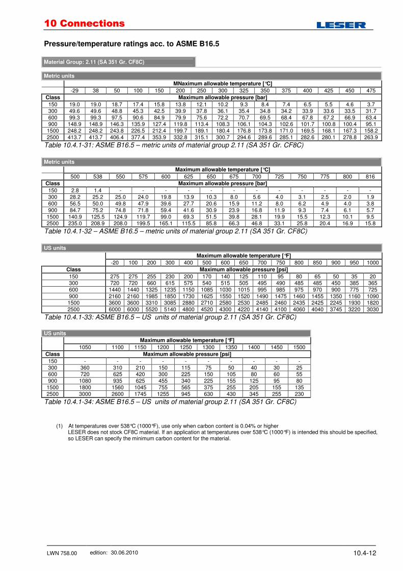
Pressure/temperature ratings acc. to ASME B16.5 Material Group: 2.11 (SA 351 Gr. CF8C)
Metric units
MNaximum allowable temperature [°C]
-29 38 50 100 150 200 250 300 325 350 375 400 425 450 475
Class Maximum allowable pressure [bar]
150 19.0 19.0 18.7 17.4 15.8 13.8 12.1 10.2 9.3 8.4 7.4 6.5 5.5 4.6 3.7 300 49.6 49.6 48.8 45.3 42.5 39.9 37.8 36.1 35.4 34.8 34.2 33.9 33.6 33.5 31.7 600 99.3 99.3 97.5 90.6 84.9 79.9 75.6 72.2 70.7 69.5 68.4 67.8 67.2 66.9 63.4 900 148.9 148.9 146.3 135.9 127.4 119.8 113.4 108.3 106.1 104.3 102.6 101.7 100.8 100.4 95.1 1500 248.2 248.2 243.8 226.5 212.4 199.7 189.1 180.4 176.8 173.8 171.0 169.5 168.1 167.3 158.2 2500 413.7 413.7 406.4 377.4 353.9 332.8 315.1 300.7 294.6 289.6 285.1 282.6 280.1 278.8 263.9
Table 10.4.1-31: ASME B16.5 – metric units of material group 2.11 (SA 351 Gr. CF8C)
Metric units
Maximum allowable temperature [°C]
500 538 550 575 600 625 650 675 700 725 750 775 800 816
Class Maximum allowable pressure [bar]
150 2.8 1.4 - - - - - - - - - - - - 300 28.2 25.2 25.0 24.0 19.8 13.9 10.3 8.0 5.6 4.0 3.1 2.5 2.0 1.9 600 56.5 50.0 49.8 47.9 39.6 27.7 20.6 15.9 11.2 8.0 6.2 4.9 4.0 3.8 900 84.7 75.2 74.8 71.8 59.4 41.6 30.9 23.9 16.8 11.9 9.3 7.4 6.1 5.7
1500 140.9 125.5 124.9 119.7 99.0 69.3 51.5 39.8 28.1 19.9 15.5 12.3 10.1 9.5 2500 235.0 208.9 208.0 199.5 165.1 115.5 85.8 66.3 46.8 33.1 25.8 20.4 16.9 15.8
Table 10.4.1-32 – ASME B16.5 – metric units of material group 2.11 (SA 351 Gr. CF8C)
US units
Maximum allowable temperature [°F]
-20 100 200 300 400 500 600 650 700 750 800 850 900 950 1000
Class Maximum allowable pressure [psi]
150 275 275 255 230 200 170 140 125 110 95 80 65 50 35 20 300 720 720 660 615 575 540 515 505 495 490 485 485 450 385 365 600 1440 1440 1325 1235 1150 1085 1030 1015 995 985 975 970 900 775 725 900 2160 2160 1985 1850 1730 1625 1550 1520 1490 1475 1460 1455 1350 1160 1090 1500 3600 3600 3310 3085 2880 2710 2580 2530 2485 2460 2435 2425 2245 1930 1820 2500 6000 6000 5520 5140 4800 4520 4300 4220 4140 4100 4060 4040 3745 3220 3030
Table 10.4.1-33: ASME B16.5 – US units of material group 2.11 (SA 351 Gr. CF8C)
US units
Maximum allowable temperature [°F]
1050 1100 1150 1200 1250 1300 1350 1400 1450 1500
Class Maximum allowable pressure [psi]
150 - - - - - - - - - - 300 360 310 210 150 115 75 50 40 30 25 600 720 625 420 300 225 150 105 80 60 55 900 1080 935 625 455 340 225 155 125 95 80
1500 1800 1560 1045 755 565 375 255 205 155 135 2500 3000 2600 1745 1255 945 630 430 345 255 230
Table 10.4.1-34: ASME B16.5 – US units of material group 2.11 (SA 351 Gr. CF8C)
(1) At temperatures over 538°C (1000°F), use only when carbon content is 0.04% or higher LESER does not stock CF8C material. If an application at temperatures over 538°C (1000°F) is intended this should be specified, so LESER can specify the minimum carbon content for the material.
1100 CCoonnnneeccttiioonnss
LWN 758.00 edition: 30.06.2010 10.4-13
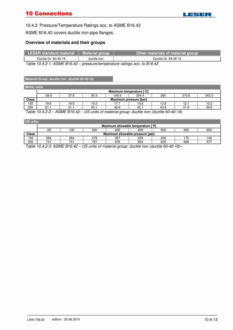
10.4.2 Pressure/Temperature Ratings acc. to ASME B16.42
ASME B16.42 covers ductile iron pipe flanges. Overview of materials and their groups
LESER standard material Material group Other materials of material group
Ductile Gr. 60-40-18 ductile iron Ductile Gr. 65-45-15
Table 10.4.2-1: ASME B16.42 – pressure/temperature ratings acc. to B16.42
Material Group: ductile iron (ductile 60-40-18)
Metric units
Maximum temperature [°C]
-28.9 37.8 93.3 148.9 204.4 260 315.6 343.3
Class Maximum pressure [bar]
150 19.6 19.6 19.2 17.7 15.8 13.8 12.1 10.2 300 51.1 51.1 50.1 46.6 45.1 43.8 41.9 39.8
Table 10.4.2-2 – ASME B16.42 – US units of material group: ductile iron (ductile 60-40-18)
US units
Maximum allowable temperature [°F]
-20 100 200 300 400 500 600 650
Class Maximum allowable pressure [psi]
150 284 284 278 257 229 200 175 148 300 741 741 727 676 654 635 608 577
Table 10.4.2-3: ASME B16.42 – US units of material group: ductile iron (ductile 60-40-18)–
1100 CCoonnnneeccttiioonnss
LWN 758.00 edition: 30.06.2010 10.4-14
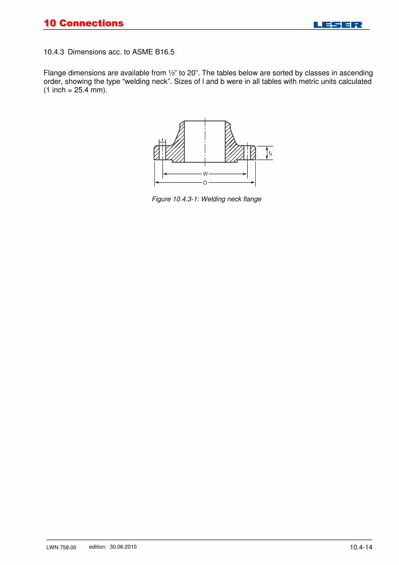
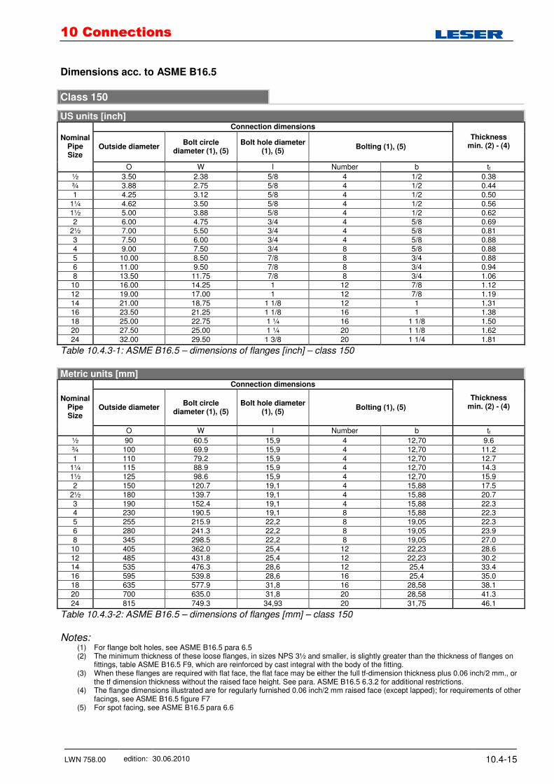
10.4.3 Dimensions acc. to ASME B16.5
Flange dimensions are available from ½” to 20”. The tables below are sorted by classes in ascending order, showing the type “welding neck”. Sizes of l and b were in all tables with metric units calculated (1 inch = 25.4 mm).
Figure 10.4.3-1: Welding neck flange
l
1100 CCoonnnneeccttiioonnss
LWN 758.00 edition: 30.06.2010 10.4-15
Dimensions acc. to ASME B16.5
Class 150
US units [inch] Connection dimensions
Outside diameter Bolt circle
diameter (1), (5) Bolt hole diameter
(1), (5) Bolting (1), (5)
Thickness min. (2) - (4)
Nominal Pipe Size
O W l Number b tf
½ 3.50 2.38 5/8 4 1/2 0.38 ¾ 3.88 2.75 5/8 4 1/2 0.44 1 4.25 3.12 5/8 4 1/2 0.50
1¼ 4.62 3.50 5/8 4 1/2 0.56 1½ 5.00 3.88 5/8 4 1/2 0.62 2 6.00 4.75 3/4 4 5/8 0.69
2½ 7.00 5.50 3/4 4 5/8 0.81 3 7.50 6.00 3/4 4 5/8 0.88 4 9.00 7.50 3/4 8 5/8 0.88 5 10.00 8.50 7/8 8 3/4 0.88 6 11.00 9.50 7/8 8 3/4 0.94 8 13.50 11.75 7/8 8 3/4 1.06
10 16.00 14.25 1 12 7/8 1.12 12 19.00 17.00 1 12 7/8 1.19 14 21.00 18.75 1 1/8 12 1 1.31 16 23.50 21.25 1 1/8 16 1 1.38 18 25.00 22.75 1 ¼ 16 1 1/8 1.50 20 27.50 25.00 1 ¼ 20 1 1/8 1.62
24 32.00 29.50 1 3/8 20 1 1/4 1.81
Table 10.4.3-1: ASME B16.5 – dimensions of flanges [inch] – class 150
Metric units [mm]
Connection dimensions
Outside diameter Bolt circle
diameter (1), (5) Bolt hole diameter
(1), (5) Bolting (1), (5)
Thickness min. (2) - (4)
Nominal Pipe Size
O W l Number b tf
½ 90 60.5 15,9 4 12,70 9.6 ¾ 100 69.9 15,9 4 12,70 11.2 1 110 79.2 15,9 4 12,70 12.7
1¼ 115 88.9 15,9 4 12,70 14.3 1½ 125 98.6 15,9 4 12,70 15.9 2 150 120.7 19,1 4 15,88 17.5
2½ 180 139.7 19,1 4 15,88 20.7 3 190 152.4 19,1 4 15,88 22.3 4 230 190.5 19,1 8 15,88 22.3 5 255 215.9 22,2 8 19,05 22.3 6 280 241.3 22,2 8 19,05 23.9 8 345 298.5 22,2 8 19,05 27.0
10 405 362.0 25,4 12 22,23 28.6 12 485 431.8 25,4 12 22,23 30.2 14 535 476.3 28,6 12 25,4 33.4 16 595 539.8 28,6 16 25,4 35.0 18 635 577.9 31,8 16 28,58 38.1 20 700 635.0 31,8 20 28,58 41.3
24 815 749.3 34,93 20 31,75 46.1
Table 10.4.3-2: ASME B16.5 – dimensions of flanges [mm] – class 150
Notes:
(1) For flange bolt holes, see ASME B16.5 para 6.5 (2) The minimum thickness of these loose flanges, in sizes NPS 3½ and smaller, is slightly greater than the thickness of flanges on
fittings, table ASME B16.5 F9, which are reinforced by cast integral with the body of the fitting. (3) When these flanges are required with flat face, the flat face may be either the full tf-dimension thickness plus 0.06 inch/2 mm., or
the tf dimension thickness without the raised face height. See para. ASME B16.5 6.3.2 for additional restrictions. (4) The flange dimensions illustrated are for regularly furnished 0.06 inch/2 mm raised face (except lapped); for requirements of other
facings, see ASME B16.5 figure F7 (5) For spot facing, see ASME B16.5 para 6.6
1100 CCoonnnneeccttiioonnss
LWN 758.00 edition: 30.06.2010 10.4-16
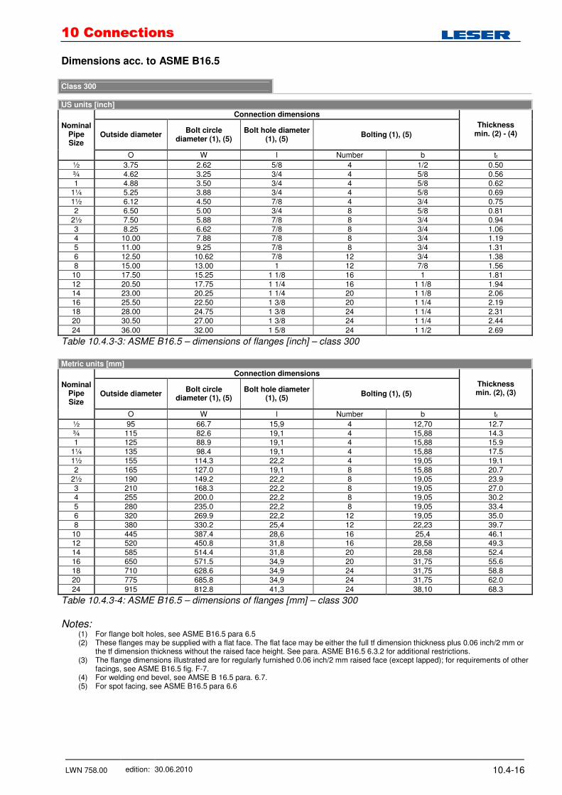
Dimensions acc. to ASME B16.5 Class 300
US units [inch]
Connection dimensions
Outside diameter Bolt circle
diameter (1), (5) Bolt hole diameter
(1), (5) Bolting (1), (5)
Thickness min. (2) - (4)
Nominal Pipe Size
O W l Number b tf
½ 3.75 2.62 5/8 4 1/2 0.50 ¾ 4.62 3.25 3/4 4 5/8 0.56 1 4.88 3.50 3/4 4 5/8 0.62
1¼ 5.25 3.88 3/4 4 5/8 0.69 1½ 6.12 4.50 7/8 4 3/4 0.75 2 6.50 5.00 3/4 8 5/8 0.81
2½ 7.50 5.88 7/8 8 3/4 0.94 3 8.25 6.62 7/8 8 3/4 1.06 4 10.00 7.88 7/8 8 3/4 1.19 5 11.00 9.25 7/8 8 3/4 1.31 6 12.50 10.62 7/8 12 3/4 1.38 8 15.00 13.00 1 12 7/8 1.56
10 17.50 15.25 1 1/8 16 1 1.81 12 20.50 17.75 1 1/4 16 1 1/8 1.94 14 23.00 20.25 1 1/4 20 1 1/8 2.06 16 25.50 22.50 1 3/8 20 1 1/4 2.19 18 28.00 24.75 1 3/8 24 1 1/4 2.31 20 30.50 27.00 1 3/8 24 1 1/4 2.44
24 36.00 32.00 1 5/8 24 1 1/2 2.69
Table 10.4.3-3: ASME B16.5 – dimensions of flanges [inch] – class 300
Metric units [mm]
Connection dimensions
Outside diameter Bolt circle
diameter (1), (5) Bolt hole diameter
(1), (5) Bolting (1), (5)
Thickness min. (2), (3)
Nominal Pipe Size
O W l Number b tf
½ 95 66.7 15,9 4 12,70 12.7 ¾ 115 82.6 19,1 4 15,88 14.3 1 125 88.9 19,1 4 15,88 15.9
1¼ 135 98.4 19,1 4 15,88 17.5 1½ 155 114.3 22,2 4 19,05 19.1 2 165 127.0 19,1 8 15,88 20.7
2½ 190 149.2 22,2 8 19,05 23.9 3 210 168.3 22,2 8 19,05 27.0 4 255 200.0 22,2 8 19,05 30.2 5 280 235.0 22,2 8 19,05 33.4 6 320 269.9 22,2 12 19,05 35.0 8 380 330.2 25,4 12 22,23 39.7
10 445 387.4 28,6 16 25,4 46.1 12 520 450.8 31,8 16 28,58 49.3 14 585 514.4 31,8 20 28,58 52.4 16 650 571.5 34,9 20 31,75 55.6 18 710 628.6 34,9 24 31,75 58.8 20 775 685.8 34,9 24 31,75 62.0
24 915 812.8 41,3 24 38,10 68.3
Table 10.4.3-4: ASME B16.5 – dimensions of flanges [mm] – class 300
Notes:
(1) For flange bolt holes, see ASME B16.5 para 6.5 (2) These flanges may be supplied with a flat face. The flat face may be either the full tf dimension thickness plus 0.06 inch/2 mm or
the tf dimension thickness without the raised face height. See para. ASME B16.5 6.3.2 for additional restrictions. (3) The flange dimensions illustrated are for regularly furnished 0.06 inch/2 mm raised face (except lapped); for requirements of other
facings, see ASME B16.5 fig. F-7. (4) For welding end bevel, see AMSE B 16.5 para. 6.7. (5) For spot facing, see ASME B16.5 para 6.6

1100 CCoonnnneeccttiioonnss
LWN 758.00 edition: 30.06.2010 10.4-17
Dimensions acc. to ASME B16.5 Class 600
US units [inch]
Connection dimensions
Outside diameter Bolt circle
diameter (2), (3) Bolt hole diameter
(2), (3) Bolting (2), (3)
Thickness min.
Nominal Pipe Size
O W l Number b tf
½ 3.75 2.62 5/8 4 1/2 0.56 ¾ 4.62 3.25 3/4 4 5/8 0.62 1 4.88 3.50 3/4 4 5/8 0.69
1¼ 5.25 3.88 3/4 4 5/8 0.81 1½ 6.12 4.50 7/8 4 3/4 0.88 2 6.50 5.00 3/4 8 5/8 1.00
2½ 7.50 5.88 7/8 8 3/4 1.12 3 8.25 6.62 7/8 8 3/4 1.25 4 10.75 8.50 1 8 7/8 1.50 5 13.00 10.50 1 1/8 8 1 1.75 6 14.00 11.50 1 1/8 12 1 1.88
Table 10.4.3-5: ASME B16.5 – dimensions of flanges [inch] – class 600
Metric units [mm]
Connection dimensions
Outside diameter Bolt circle
diameter (2), (3) Bolt hole diameter
(2), (3) Bolting (2), (3)
Thickness min.
Nominal Pipe Size
O W l Number b tf
½ 95 66.7 15,9 4 12,70 14.3 ¾ 115 82.6 19,1 4 15,88 15.9 1 125 88.9 19,1 4 15,88 17.5
1¼ 135 98.4 19,1 4 15,88 20.7 1½ 155 114.3 22,2 4 19,05 22.3 2 165 127.0 19,1 8 15,88 25.4
2½ 190 149.2 22,2 8 19,05 28.6 3 210 168.3 22,2 8 19,05 31.8 4 275 215.9 25,4 8 22,23 38.1 5 330 266.7 28,6 8 25,4 44.5 6 355 292.1 28,6 12 25,4 47.7
Table 10.4.3-6: ASME B16.5 – dimensions of flanges [mm] – class 600
Notes:
(2) For flange bolt holes, see ASME B16.5 para 6.5 (3) For spot facing, see ASME para 6.6

1100 CCoonnnneeccttiioonnss
LWN 758.00 edition: 30.06.2010 10.4-18
Dimensions acc. to ASME B16.5 Class 900
US units [inch]
Connection dimensions
Outside diameter Bolt circle
diameter (2), (3) Bolt hole diameter
(2), (3) Bolting (2), (3)
Thickness min.
Nominal Pipe Size
O W l Number b tf
½ ¾ 1
1¼ 1½ 2
2½
Use class 1500 dimensions in these sizes
3 9.50 7.50 1 8 7/8 1.50 4 11.50 9.25 1 1/4 8 1 1/8 1.75
Table 10.4.3-7: ASME B16.5 – dimensions of flanges [inch] – class 900
Metric units [mm]
Connection dimensions
Outside diameter Bolt circle
diameter (2), (3) Bolt hole diameter
(2), (3) Bolting (2), (3)
Thickness min.
Nominal Pipe Size
O W l Number b tf
½ ¾ 1
1¼ 1½ 2
2½
Use class 1500 dimensions in these sizes
3 240 190.5 25,4 8 22,23 38.1 4 290 235.0 31,8 8 28,58 44.5
Table 10.4.3-8: ASME B16.5 – dimensions of flanges [mm] – class 900
Notes: (2) For flange bolt holes, see ASME B16.5 para 6.5 (3) For spot facing, see ASME para 6.6

1100 CCoonnnneeccttiioonnss
LWN 758.00 edition: 30.06.2010 10.4-19
Dimensions acc. to ASME B16.5 Class 1500
US units [inch]
Connection dimensions
Outside diameter Bolt circle
diameter (2), (3) Bolt hole diameter
(2), (3) Bolting (2), (3)
Thickness min.
Nominal Pipe Size
O W l Number b tf
½ 4.75 3.25 7/8 4 3/4 0.88 ¾ 5.12 3.50 7/8 4 3/4 1.00 1 5.88 4.00 1 4 7/8 1.12
1¼ 6.25 4.38 1 4 7/8 1.12 1½ 7.00 4.88 1 1/8 4 1 1.25 2 8.50 6.50 1 8 7/8 1.50
2½ 9.62 7.50 1 1/8 8 1 1.62 3 10.50 8.00 1 1/4 8 1 1/8 1.88 4 12.25 9.50 1 3/8 8 1 1/4 2.12
Table 10.4.3-9: ASME B16.5 – dimensions of flanges [inch] – class 1500
Metric units [mm]
Connection dimensions
Outside diameter Bolt circle
diameter (2), (3) Bolt hole diameter
(2), (3) Bolting (2), (3)
Thickness min.
Nominal Pipe Size
O W l Number b tf
½ 120 82.6 22,2 4 19,05 22.3 ¾ 130 88.9 22,2 4 19,05 25.4 1 150 101.6 25,4 4 22,23 28.6
1¼ 160 111.1 25,4 4 22,23 28.6 1½ 180 123.8 28,6 4 25,4 31.8 2 215 165.1 25,4 8 22,23 38.1
2½ 245 190.5 28,6 8 25,4 41.3 3 265 203.2 31,8 8 28,58 47.7 4 310 241.3 34,9 8 31,75 54.0
Table 10.4.3-10: ASME B16.5 – dimensions of flanges [mm] – class 1500
Notes:
(2) For flange bolt holes, see ASME B16.5 para 6.5 (3) For spot facing, see ASME para 6.6
1100 CCoonnnneeccttiioonnss
LWN 758.00 edition: 30.06.2010 10.4-20
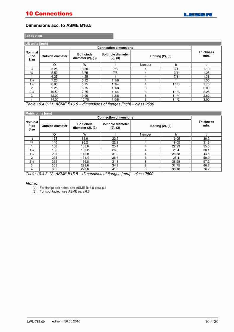
Dimensions acc. to ASME B16.5 Class 2500
US units [inch]
Connection dimensions
Outside diameter Bolt circle
diameter (2), (3) Bolt hole diameter
(2), (3) Bolting (2), (3)
Thickness min.
Nominal Pipe Size
O W l Number b tf
½ 5.25 3.50 7/8 4 3/4 1.19 ¾ 5.50 3.75 7/8 4 3/4 1.25 1 6.25 4.25 1 4 7/8 1.38
1¼ 7.25 5.12 1 1/8 4 1 1.50 1½ 8.00 5.75 1 1/4 4 1 1/8 1.75 2 9.25 6.75 1 1/8 8 1 2.00
2½ 10.50 7.75 1 1/4 8 1 1/8 2.25 3 12.00 9.00 1 3/8 8 1 1/4 2.62 4 14.00 10.75 1 5/8 8 1 1/2 3.00
Table 10.4.3-11: ASME B16.5 – dimensions of flanges [inch] – class 2500
Metric units [mm]
Connection dimensions
Outside diameter Bolt circle
diameter (2), (3) Bolt hole diameter
(2), (3) Bolting (2), (3)
Thickness min.
Nominal Pipe Size
O W l Number b tf
½ 135 88.9 22,2 4 19,05 30.2 ¾ 140 95.2 22,2 4 19,05 31.8 1 160 108.0 25,4 4 22,23 35.0
1¼ 185 130.2 28,6 4 25,4 38.1 1½ 205 146.0 31,8 4 28,58 44.5 2 235 171.4 28,6 8 25,4 50.9
2½ 265 196.8 31,8 8 28,58 57.2 3 305 228.6 34,9 8 31,75 66.7 4 355 273.0 41,3 8 38,10 76.2
Table 10.4.3-12: ASME B16.5 – dimensions of flanges [mm] – class 2500
Notes:
(2) For flange bolt holes, see ASME B16.5 para 6.5 (3) For spot facing, see ASME para 6.6

1100 CCoonnnneeccttiioonnss
LWN 758.00 edition: 30.06.2010 10.4-21
10.4.4 Flange Facings and Finish acc. to ASME B16.5
Forms of flange facings are shown in Fig. 10.4.4-1 and their dimensions in Tab. 10.4.4-1. For flat face (FF) flange facings see section 4.6.
tf
tf
R
R
WX L
SSmallmale
Y WSmallgroove
Smalltongue
Smallandlargegroove
Smallandlargetongue
Largegroove
Largetongue
Largemale
Smallfemale
Largefemale
AA, BB, CC, etc.[Notes (1), (2)]
AA, BB, CC, etc.[Notes (1), (2)]
gnittif fo en ilr etn eC
gnittif fo en ilr etn eC
0.06
0.25
T R
0.25
Z
P
U
L
E
R
Note (4)
Note (4)
0.25
0.19
0.06 raised faceregularly furnishedon Classes 150 and300 unless otherwiseordered
0.25 raised facefurnished on Classes400 and higherunless otherwiseordered
Large or smallmale face[Notes (3), (9)]
Large or smallfemale face[Notes (3), (9)]
Large or smallgroove face[Notes (3),(9)]
Large or smalltongue face[Notes (3),(9)]
Ring jointface
K (Note (5)]
K (Note (5)]
K ( Note (6)]
0.19
HH, JJ, KK, etc.[Notes (1), (2)]
Figure 10.4.4-1: ASME B16.5 – End flange facings [inch] and their relationship to flange thickness and Center-To-End and End-To-End dimensions
Dimensions of facings other than ring joints [inch]
Outside diameter Outside diameter Height
Minimum outside
diameter of raised portion
(15), (9)
RF, LMF and LTF
SMF (4), (10)
STF
Inside diameter of LTF
and STF LFF and
LGF SFF (4),
(10) SGF
Inside Diameter of LGF
and SGF SFF and SGF
LFF andLGF
Nom-inal pipe size
R S T U
Inside diameter of SMF (4), (10)
W X Y Z
RF (11), (12)
SMF, LMF, STF and LTF (11),
(13)
Depth of
groove or
female (11), (14)
K L
½ 1.38 0.72 1.38 1.00 - 1.44 0.78 1.44 0.94 - - - 1.75 1.81 ¾ 1.69 0.94 1.69 1.31 - 1.75 1.00 1.75 1.25 - - - 2.06 2.12 1 2.00 1.19 1.88 1.50 - 2.06 1.25 1.94 1.44 - - - 2.25 2.44
1¼ 2.50 1.50 2.25 1.88 - 2.56 1.56 2.31 1.81 - - - 2.62 2.94 1½ 2.88 1.75 2.50 2.12 - 2.94 1.81 2.56 2.06 - - - 2.88 3.31 2 3.62 2.25 3.25 2.88 - 3.69 2.31 3.31 2.81 - - - 3.62 4.06
2½ 4.12 2.69 3.75 3.38 - 4.19 2.75 3.81 3.31 - - - 4.12 4.56 3 5.00 3.31 4.62 4.25 - 5.06 3.38 4.69 4.19 - - - 5.00 5.44
3½ 5.50 3.81 5.12 4.75 - 5.56 3.88 5.19 4.69 - - - 5.50 5.94 4 6.19 4.31 5.69 5.19 - 6.25 4.38 5.75 5.12 - - - 6.19 6.62 5 7.31 5.38 6.81 6.31 - 7.38 5.44 6.88 6.25 - - - 7.31 7.75 6 8.50 6.38 8.00 7.50 - 8.56 6.44 8.06 7.44 - - - 8.50 8.94 8 10.62 8.38 10.00 9.38 - 10.69 8.44 10.06 9.31 - - - 10.62 11.06 10 12.75 10.50 12.00 11.25 - 12.81 10.56 12.06 11.19 - - - 12.75 13.19 12 15.00 12.50 14.25 13.50 - 15.06 12.56 14.31 13.44 - - - 15.00 15.44 14 16.25 13.75 15.50 14.75 - 16.31 13.81 15.56 14.69 - - - 16.25 16.69 16 18.50 15.75 17.62 16.75 - 18.56 15.81 17.69 16.69 - - - 18.50 18.94 18 21.00 17.75 20.12 19.25 - 21.06 17.81 20.19 19.19 - - - 21.00 21.44 20 23.00 19.75 22.00 21.00 - 23.06 19.81 22.06 20.94 - - - 23.00 23.44
24 27.25 23.75 26.25 25.25 - 27.31 23.81 26.31 25.19 - - - 27.25 27.69
Table 10.4.4-1: ASME B16.5 – Dimensions other than ring joints [inch]
1100 CCoonnnneeccttiioonnss
LWN 758.00 edition: 30.06.2010 10.4-22
Shortcuts:
RF raised face SMF small male facing LMF large male facing SFF small female facing LFF large female facing STF small tongue facing LTF large tongue facing SGF small groove facing LGF large groove facing
General Notes table 10.4.4-1:
(a) For facing requirements for flanges end flanged fittings, see paras. 6.3 and 6.4 and Fig. F7. (b) For facing requirements for lapped joints, see para. 6.4.3 and Fig. F7 (c) For facing tolerances, see para 7.3
Notes:
(1) See ASME B16.5 paras. 6.2 and 6.4 (2) See tables below (3) See table 10.4.4-1 for dimensions of facings (other than ring joint) and table 10.4.4-2 (4) For small male and female joints, care should be taken in the use of these dimensions to insure that the inside diameter of fitting
pipe is small enough to permit sufficient bearing surface to prevent crushing of the gasket (see ASME B16.5 table F4). This applies particularly on lines where the joint is made on the end of the pipe. Threaded companion flanges for small male and female joints are furnished with plain face and are threaded with American Standard Locknut Thread (NPSL).
(5) See ASME B16.5 table F4 (6) See section 4.3 or ASME B16.5 table F5 (7) See ASME B16.5 para. 6.4.3 (8) See ASME B16.5 para. 6.4.3.5 and table F5 (9) Large male and female faces and large tongue and groove are not applicable to class 150 because of potential dimensional
conflicts (10) Inside diameter of fitting should match inside diameter of pipe as specified by purchaser. (11) See para. 6.4.3 and Fig. F7 for thickness and outside diameter of laps. (12) Height of raised face either 0.06 in. of 0.25 in. (13) Height of large and small male and tongue is 0.25 in. (14) Depth of groove or female is 0.19 in. (15) Raised portion of full face may be furnished unless otherwise specified an order.
1100 CCoonnnneeccttiioonnss
LWN 758.00 edition: 30.06.2010 10.4-23
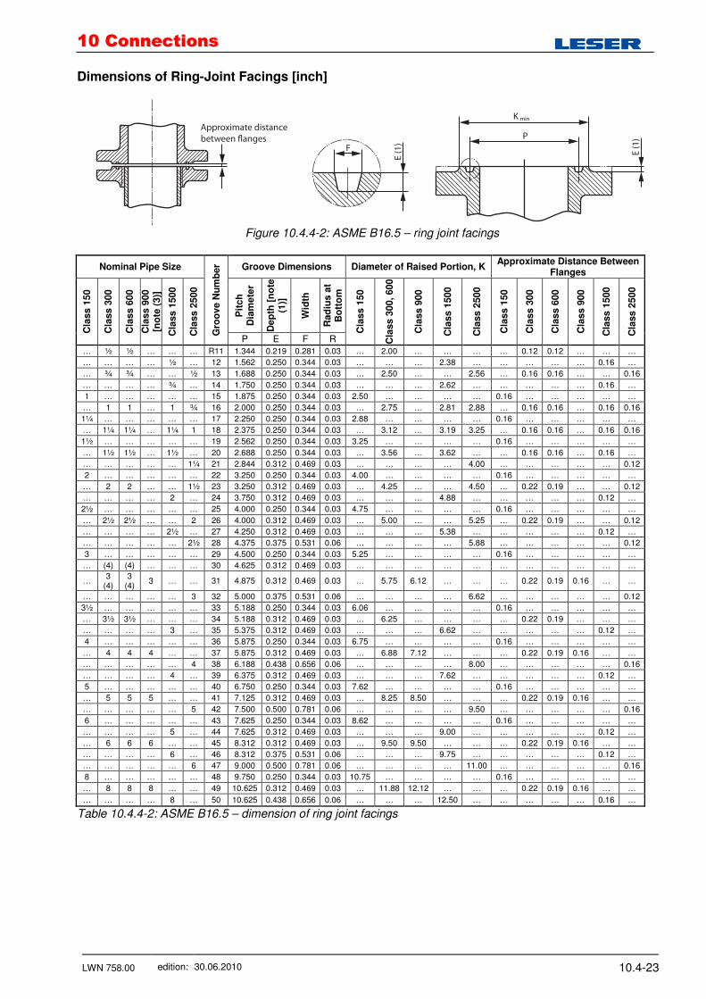
Dimensions of Ring-Joint Facings [inch]
Figure 10.4.4-2: ASME B16.5 – ring joint facings
Nominal Pipe Size Groove Dimensions Diameter of Raised Portion, K Approximate Distance Between
Flanges
Pit
ch
D
iam
ete
r
Dep
th [
no
te
(1)]
Wid
th
Rad
ius a
t B
ott
om
Cla
ss 1
50
Cla
ss 3
00
Cla
ss 6
00
Cla
ss 9
00
[no
te (
3)]
Cla
ss 1
500
Cla
ss 2
500
Gro
ove N
um
ber
P E F R
Cla
ss 1
50
Cla
ss 3
00,
600
Cla
ss 9
00
Cla
ss 1
500
Cla
ss 2
500
Cla
ss 1
50
Cla
ss 3
00
Cla
ss 6
00
Cla
ss 9
00
Cla
ss 1
500
Cla
ss 2
500
… ½ ½ … … … R11 1.344 0.219 0.281 0.03 … 2.00 … … … … 0.12 0.12 … … …
… … … … ½ … 12 1.562 0.250 0.344 0.03 … … … 2.38 … … … … … 0.16 …
… ¾ ¾ … … ½ 13 1.688 0.250 0.344 0.03 … 2.50 … … 2.56 … 0.16 0.16 … … 0.16
… … … … ¾ … 14 1.750 0.250 0.344 0.03 … … … 2.62 … … … … … 0.16 …
1 … … … … … 15 1.875 0.250 0.344 0.03 2.50 … … … … 0.16 … … … … …
… 1 1 … 1 ¾ 16 2.000 0.250 0.344 0.03 … 2.75 … 2.81 2.88 … 0.16 0.16 … 0.16 0.16
1¼ … … … … … 17 2.250 0.250 0.344 0.03 2.88 … … … … 0.16 … … … … …
… 1¼ 1¼ … 1¼ 1 18 2.375 0.250 0.344 0.03 … 3.12 … 3.19 3.25 … 0.16 0.16 … 0.16 0.16
1½ … … … … … 19 2.562 0.250 0.344 0.03 3.25 … … … … 0.16 … … … … …
… 1½ 1½ … 1½ … 20 2.688 0.250 0.344 0.03 … 3.56 … 3.62 … … 0.16 0.16 … 0.16 …
… … … … … 1¼ 21 2.844 0.312 0.469 0.03 … … … … 4.00 … … … … … 0.12
2 … … … … … 22 3.250 0.250 0.344 0.03 4.00 … … … … 0.16 … … … … …
… 2 2 … … 1½ 23 3.250 0.312 0.469 0.03 … 4.25 … … 4.50 … 0.22 0.19 … … 0.12
… … … … 2 … 24 3.750 0.312 0.469 0.03 … … … 4.88 … … … … … 0.12 …
2½ … … … … … 25 4.000 0.250 0.344 0.03 4.75 … … … … 0.16 … … … … …
… 2½ 2½ … … 2 26 4.000 0.312 0.469 0.03 … 5.00 … … 5.25 … 0.22 0.19 … … 0.12
… … … … 2½ … 27 4.250 0.312 0.469 0.03 … … … 5.38 … … … … … 0.12 …
… … … … … 2½ 28 4.375 0.375 0.531 0.06 … … … … 5.88 … … … … … 0.12
3 … … … … … 29 4.500 0.250 0.344 0.03 5.25 … … … … 0.16 … … … … …
… (4) (4) … … … 30 4.625 0.312 0.469 0.03 … … … … … … … … … … …
… 3
(4) 3
(4) 3 … … 31 4.875 0.312 0.469 0.03 … 5.75 6.12 … … … 0.22 0.19 0.16 … …
… … … … … 3 32 5.000 0.375 0.531 0.06 … … … … 6.62 … … … … … 0.12
3½ … … … … … 33 5.188 0.250 0.344 0.03 6.06 … … … … 0.16 … … … … …
… 3½ 3½ … … … 34 5.188 0.312 0.469 0.03 … 6.25 … … … … 0.22 0.19 … … …
… … … … 3 … 35 5.375 0.312 0.469 0.03 … … … 6.62 … … … … … 0.12 …
4 … … … … … 36 5.875 0.250 0.344 0.03 6.75 … … … … 0.16 … … … … …
… 4 4 4 … … 37 5.875 0.312 0.469 0.03 … 6.88 7.12 … … … 0.22 0.19 0.16 … …
… … … … … 4 38 6.188 0.438 0.656 0.06 … … … … 8.00 … … … … … 0.16
… … … … 4 … 39 6.375 0.312 0.469 0.03 … … … 7.62 … … … … … 0.12 …
5 … … … … … 40 6.750 0.250 0.344 0.03 7.62 … … … … 0.16 … … … … …
… 5 5 5 … … 41 7.125 0.312 0.469 0.03 … 8.25 8.50 … … … 0.22 0.19 0.16 … …
… … … … … 5 42 7.500 0.500 0.781 0.06 … … … … 9.50 … … … … … 0.16
6 … … … … … 43 7.625 0.250 0.344 0.03 8.62 … … … … 0.16 … … … … …
… … … … 5 … 44 7.625 0.312 0.469 0.03 … … … 9.00 … … … … … 0.12 …
… 6 6 6 … … 45 8.312 0.312 0.469 0.03 … 9.50 9.50 … … … 0.22 0.19 0.16 … …
… … … … 6 … 46 8.312 0.375 0.531 0.06 … … … 9.75 … … … … … 0.12 …
… … … … … 6 47 9.000 0.500 0.781 0.06 … … … … 11.00 … … … … … 0.16
8 … … … … … 48 9.750 0.250 0.344 0.03 10.75 … … … … 0.16 … … … … …
… 8 8 8 … … 49 10.625 0.312 0.469 0.03 … 11.88 12.12 … … … 0.22 0.19 0.16 … …
… … … … 8 … 50 10.625 0.438 0.656 0.06 … … … 12.50 … … … … … 0.16 …
Table 10.4.4-2: ASME B16.5 – dimension of ring joint facings
1100 CCoonnnneeccttiioonnss
LWN 758.00 edition: 30.06.2010 10.4-24
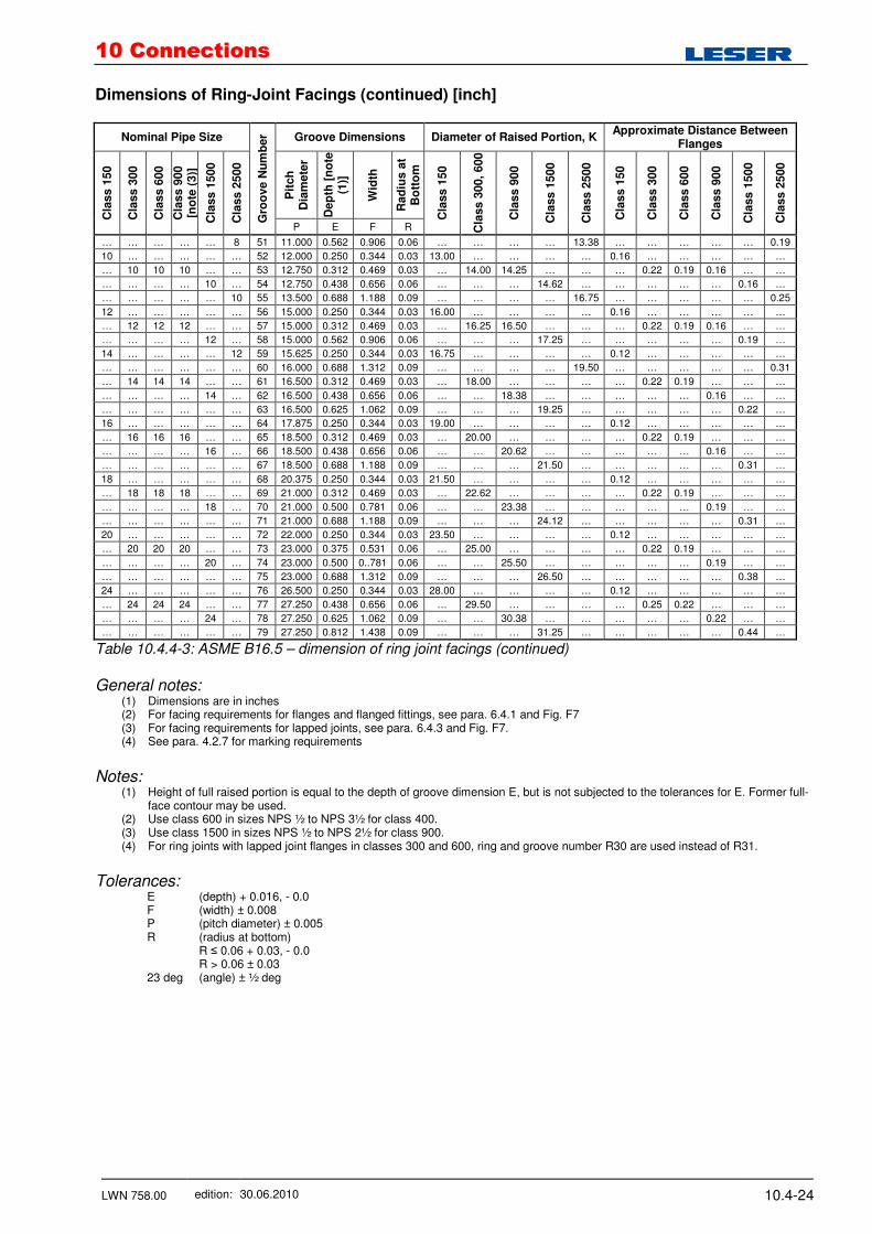
Dimensions of Ring-Joint Facings (continued) [inch]
Nominal Pipe Size Groove Dimensions Diameter of Raised Portion, K Approximate Distance Between
Flanges
Pit
ch
D
iam
ete
r
Dep
th [
no
te
(1)]
Wid
th
Rad
ius a
t B
ott
om
Cla
ss 1
50
Cla
ss 3
00
Cla
ss 6
00
Cla
ss 9
00
[no
te (
3)]
Cla
ss 1
500
Cla
ss 2
500
Gro
ove N
um
ber
P E F R
Cla
ss 1
50
Cla
ss 3
00,
600
Cla
ss 9
00
Cla
ss 1
500
Cla
ss 2
500
Cla
ss 1
50
Cla
ss 3
00
Cla
ss 6
00
Cla
ss 9
00
Cla
ss 1
500
Cla
ss 2
500
… … … … … 8 51 11.000 0.562 0.906 0.06 … … … … 13.38 … … … … … 0.19
10 … … … … … 52 12.000 0.250 0.344 0.03 13.00 … … … … 0.16 … … … … …
… 10 10 10 … … 53 12.750 0.312 0.469 0.03 … 14.00 14.25 … … … 0.22 0.19 0.16 … …
… … … … 10 … 54 12.750 0.438 0.656 0.06 … … … 14.62 … … … … … 0.16 …
… … … … … 10 55 13.500 0.688 1.188 0.09 … … … … 16.75 … … … … … 0.25
12 … … … … … 56 15.000 0.250 0.344 0.03 16.00 … … … … 0.16 … … … … …
… 12 12 12 … … 57 15.000 0.312 0.469 0.03 … 16.25 16.50 … … … 0.22 0.19 0.16 … …
… … … … 12 … 58 15.000 0.562 0.906 0.06 … … … 17.25 … … … … … 0.19 …
14 … … … … 12 59 15.625 0.250 0.344 0.03 16.75 … … … … 0.12 … … … … …
… … … … … … 60 16.000 0.688 1.312 0.09 … … … … 19.50 … … … … … 0.31
… 14 14 14 … … 61 16.500 0.312 0.469 0.03 … 18.00 … … … … 0.22 0.19 … … …
… … … … 14 … 62 16.500 0.438 0.656 0.06 … … 18.38 … … … … … 0.16 … …
… … … … … … 63 16.500 0.625 1.062 0.09 … … … 19.25 … … … … … 0.22 …
16 … … … … … 64 17.875 0.250 0.344 0.03 19.00 … … … … 0.12 … … … … …
… 16 16 16 … … 65 18.500 0.312 0.469 0.03 … 20.00 … … … … 0.22 0.19 … … …
… … … … 16 … 66 18.500 0.438 0.656 0.06 … … 20.62 … … … … … 0.16 … …
… … … … … … 67 18.500 0.688 1.188 0.09 … … … 21.50 … … … … … 0.31 …
18 … … … … … 68 20.375 0.250 0.344 0.03 21.50 … … … … 0.12 … … … … …
… 18 18 18 … … 69 21.000 0.312 0.469 0.03 … 22.62 … … … … 0.22 0.19 … … …
… … … … 18 … 70 21.000 0.500 0.781 0.06 … … 23.38 … … … … … 0.19 … …
… … … … … … 71 21.000 0.688 1.188 0.09 … … … 24.12 … … … … … 0.31 …
20 … … … … … 72 22.000 0.250 0.344 0.03 23.50 … … … … 0.12 … … … … …
… 20 20 20 … … 73 23.000 0.375 0.531 0.06 … 25.00 … … … … 0.22 0.19 … … …
… … … … 20 … 74 23.000 0.500 0..781 0.06 … … 25.50 … … … … … 0.19 … …
… … … … … … 75 23.000 0.688 1.312 0.09 … … … 26.50 … … … … … 0.38 …
24 … … … … … 76 26.500 0.250 0.344 0.03 28.00 … … … … 0.12 … … … … …
… 24 24 24 … … 77 27.250 0.438 0.656 0.06 … 29.50 … … … … 0.25 0.22 … … …
… … … … 24 … 78 27.250 0.625 1.062 0.09 … … 30.38 … … … … … 0.22 … …
… … … … … … 79 27.250 0.812 1.438 0.09 … … … 31.25 … … … … … 0.44 …
Table 10.4.4-3: ASME B16.5 – dimension of ring joint facings (continued)
General notes:
(1) Dimensions are in inches (2) For facing requirements for flanges and flanged fittings, see para. 6.4.1 and Fig. F7 (3) For facing requirements for lapped joints, see para. 6.4.3 and Fig. F7. (4) See para. 4.2.7 for marking requirements
Notes:
(1) Height of full raised portion is equal to the depth of groove dimension E, but is not subjected to the tolerances for E. Former full-face contour may be used.
(2) Use class 600 in sizes NPS ½ to NPS 3½ for class 400. (3) Use class 1500 in sizes NPS ½ to NPS 2½ for class 900. (4) For ring joints with lapped joint flanges in classes 300 and 600, ring and groove number R30 are used instead of R31.
Tolerances: E (depth) + 0.016, - 0.0 F (width) ± 0.008 P (pitch diameter) ± 0.005 R (radius at bottom) R ≤ 0.06 + 0.03, - 0.0 R > 0.06 ± 0.03 23 deg (angle) ± ½ deg
1100 CCoonnnneeccttiioonnss
LWN 758.00 edition: 30.06.2010 10.4-25
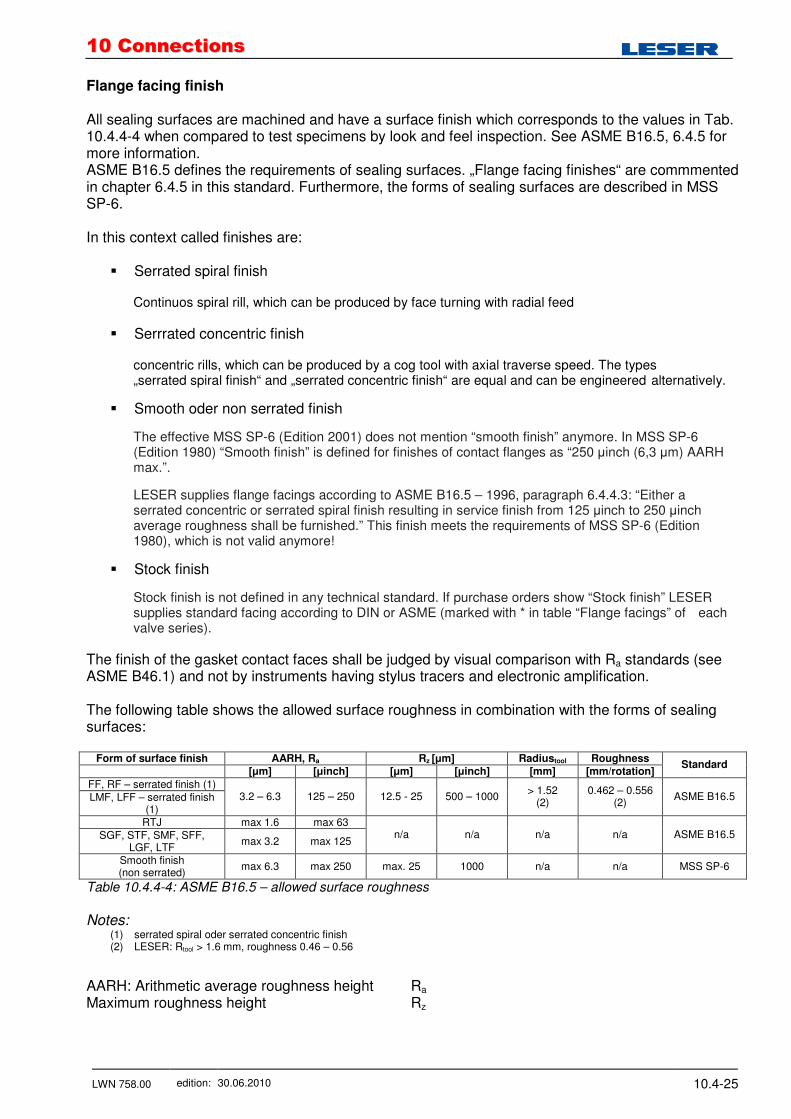
Flange facing finish All sealing surfaces are machined and have a surface finish which corresponds to the values in Tab. 10.4.4-4 when compared to test specimens by look and feel inspection. See ASME B16.5, 6.4.5 for more information. ASME B16.5 defines the requirements of sealing surfaces. „Flange facing finishes“ are commmented in chapter 6.4.5 in this standard. Furthermore, the forms of sealing surfaces are described in MSS SP-6. In this context called finishes are:
� Serrated spiral finish Continuos spiral rill, which can be produced by face turning with radial feed
� Serrrated concentric finish concentric rills, which can be produced by a cog tool with axial traverse speed. The types „serrated spiral finish“ and „serrated concentric finish“ are equal and can be engineered alternatively.
� Smooth oder non serrated finish
The effective MSS SP-6 (Edition 2001) does not mention “smooth finish” anymore. In MSS SP-6 (Edition 1980) “Smooth finish” is defined for finishes of contact flanges as “250 µinch (6,3 µm) AARH max.”.
LESER supplies flange facings according to ASME B16.5 – 1996, paragraph 6.4.4.3: “Either a serrated concentric or serrated spiral finish resulting in service finish from 125 µinch to 250 µinch average roughness shall be furnished.” This finish meets the requirements of MSS SP-6 (Edition 1980), which is not valid anymore!
� Stock finish
Stock finish is not defined in any technical standard. If purchase orders show “Stock finish” LESER supplies standard facing according to DIN or ASME (marked with * in table “Flange facings” of each valve series).
The finish of the gasket contact faces shall be judged by visual comparison with Ra standards (see ASME B46.1) and not by instruments having stylus tracers and electronic amplification. The following table shows the allowed surface roughness in combination with the forms of sealing surfaces:
Form of surface finish AARH, Ra Rz [µm] Radiustool Roughness
[µm] [µinch] [µm] [µinch] [mm] [mm/rotation] Standard
FF, RF – serrated finish (1) LMF, LFF – serrated finish
(1) 3.2 – 6.3 125 – 250 12.5 - 25 500 – 1000
> 1.52 (2)
0.462 – 0.556 (2)
ASME B16.5
RTJ max 1.6 max 63 SGF, STF, SMF, SFF,
LGF, LTF max 3.2 max 125
n/a n/a n/a n/a ASME B16.5
Smooth finish (non serrated)
max 6.3 max 250 max. 25 1000 n/a n/a MSS SP-6
Table 10.4.4-4: ASME B16.5 – allowed surface roughness
Notes:
(1) serrated spiral oder serrated concentric finish (2) LESER: Rtool > 1.6 mm, roughness 0.46 – 0.56
AARH: Arithmetic average roughness height Ra Maximum roughness height Rz

1100 CCoonnnneeccttiioonnss
LWN 758.00 edition: 30.06.2010 10.4-26
10.4.5 Flange Ratings acc. to API 526
Besides ASME B16.5 / B16.34 also API 526 lists pressure-temperature ratings for flanges. This section explains the differences between these standards. Related to the pressure/temperature limits the standards ASME B16.5 / B16.34 and API 526 are identical to a certain extent. The differences are:
- acc. to API 526 the pressure/temperature limit of the highest flange class in all orifices is lower than the limit in ASME B16.5 / B16.34
- for API orifices L through T the pressure / temperature limits also for lower flange classes deviate from the values of ASME B16.5 / B16.34
- there are less intermediate temperature steps in the API 526. See chapter 4.1 for ASME and LESER catalogue for API limits. In case the pressure/temperature limit acc. to API 526 is lower than the limit acc. to ASME B16.5 / B16.34, the LESER type 526 can usually be supplied with a set pressure in accordance with the ASME B16.5 / B16.34 flange rating. The limiting factor however may be the spring chart (LWN 060.30 and LWN 062.30). Class 300L according to API 526 A Class 300L flange is dimensionally identical to a Class 300 flange. The maximum set pressure of an API valve with a Class 300L inlet flange however is the same as for a Class 150 flange at ambient temperatures. The difference to a Class 150 inlet flange is that the maximum set pressure is extended to a temperature of 800°F/427°C. The application area for #300L inlet flanges is shown in the following chart.
Figute 10.4.5-1: Application area for #300L inlet flages
1100 CCoonnnneeccttiioonnss
LWN 758.00 edition: 30.06.2010 10.4-27
10.4.6 Cast Iron and Ductile Iron Flanges acc. to ASME B 16.1 and ASME B 16.42
Cast Iron According to ASME B16.1 cast iron equates to class 125 and class 250. In general flat face flange facing (FF) is required. Cast iron castings for LESER valves generally don’t allow to machine a flat face without falling below the minimum thickness of the flange. Therefore class 125 and 250 are not offered by LESER. Connecting dimensions of class 125 and 250 are equal to class 150 respectively class 300 for steel flanges. Following connection dimensions of flanges are equal:
Iron Steel
#125 #150 #250 #300
Table 10.4.6-1: Equal connection dimensions of flanges
Note: A flat face flange facing for a carbon steel or stainless steel safety valve can be supplied only after verification and confirmation by LESER. Flat face flange facing is not possible for
- all full nozzle design, like Type 526 or 458 or Type 488 - Critical Service safety valves Type 447 and 546 - Compact Performance safety valves equipped with flanges
Ductile Iron According to ASME B16.42 ductile Iron equates to class 150 and class 300. Class 150: Flat Face (FF) or Raised Face (RF) Class 300: Raised Face (RF) LESER can supply ductile iron valves, e.g. type 4415 or 4335 with raised face in class 150.
1100 CCoonnnneeccttiioonnss
LWN 758.00 edition: 30.06.2010 10.4-28
10.4.7 LCB, WCB and European Codes & Standards
LESER sources LCB with a fivefold material certificate for WCB, WCC, LCB, LCC and 1.0619. That means chemical composition and mechanical properties of the material fulfill the requirements of all five materials designations. The applicability of WCB and LCB according to European Standards can be taken from the following EN standards:
1. EN 1503-2: „Valves - Materials for bodies, bonnets and covers“ Part 2 of this standard contains steels for pressure retaining valve bodies, bonnets and covers which are not part of European material standards. WCB and LCB can be found in table 1, page 5.
2. EN 12516-1: „Industrial valves – shell designs strength – part 1: Calculation method for steel
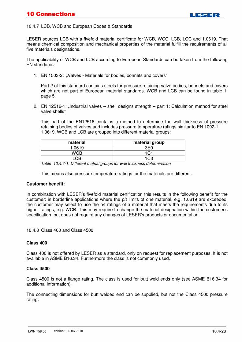
valve shells” This part of the EN12516 contains a method to determine the wall thickness of pressure retaining bodies of valves and includes pressure temperature ratings similar to EN 1092-1. 1.0619, WCB and LCB are grouped into different material groups:
material material group 1.0619 3E0 WCB 1C1 LCB 1C3
Table 10.4.7-1: Different matrial groups for wall thickness determination
This means also pressure temperature ratings for the materials are different.
Customer benefit: In combination with LESER’s fivefold material certification this results in the following benefit for the customer: in borderline applications where the p/t limits of one material, e.g. 1.0619 are exceeded, the customer may select to use the p/t ratings of a material that meets the requirements due to its higher ratings, e.g. WCB. This may require to change the material designation within the customer’s specification, but does not require any changes of LESER’s products or documentation. 10.4.8 Class 400 and Class 4500
Class 400 Class 400 is not offered by LESER as a standard, only on request for replacement purposes. It is not available in ASME B16.34. Furthermore the class is not commonly used. Class 4500 Class 4500 is not a flange rating. The class is used for butt weld ends only (see ASME B16.34 for additional information). The connecting dimensions for butt welded end can be supplied, but not the Class 4500 pressure rating.
1100 CCoonnnneeccttiioonnss
LWN 758.00 edition: 30.06.2010 10.4-29
10.4.9 LESER Specific Details
Lap joint flanges See section 3.6 for more information Machining of flange thickness and outer flange diameter for cast bodies See section 3.6 for more information Flattened outlet diameter See section 3.6 for more information Inlet flange dimensions of full nozzle safety valves Flange thickness is fully in accordance with API standard 526, section 2.4. Dimensions, which states that: “For some valve designs, the inlet raised face height may substantially exceed the nominal dimension specified in ASME. Consult the manufacturer for exact dimensions.” Full nozzle safety valves like LESER API Series 526 exceed the flange thickness stated in ASME B16.5 of the inlet flange due to:
- Height of nozzle sealing face installed in the valve inlet - The outer diameter of the nozzle thread, screwed into the body inlet, requires a flange
thickness larger than specified in ASME / ANSI B16.5 to achieve the required pressure rating. This results in:
- Valve body is more rigid and therefore less prone to distortion caused by stresses induced by piping loads during installation, this preserves factory seat tightness acc. to API 527
- During installation, bolting requirements should be calculated using the “S” dimension stated in the LESER API catalogue, please do not hesitate to contact us if you need any assistance
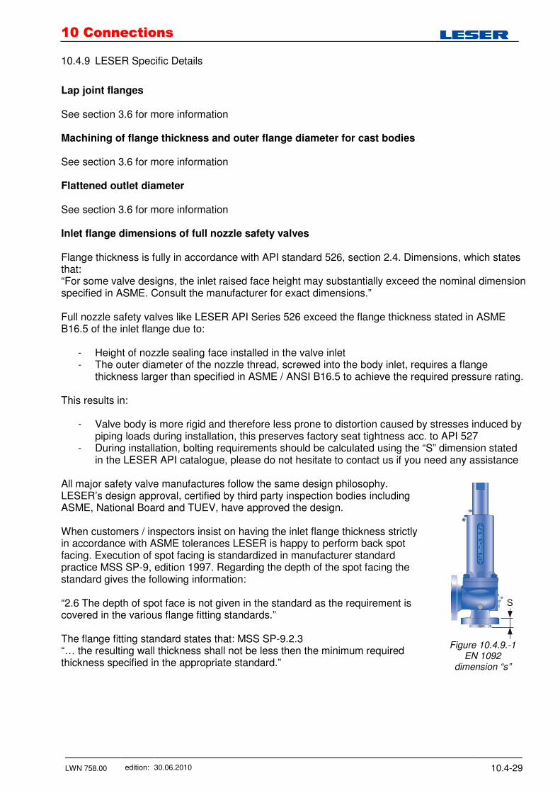
All major safety valve manufactures follow the same design philosophy. LESER’s design approval, certified by third party inspection bodies including ASME, National Board and TUEV, have approved the design. When customers / inspectors insist on having the inlet flange thickness strictly in accordance with ASME tolerances LESER is happy to perform back spot facing. Execution of spot facing is standardized in manufacturer standard practice MSS SP-9, edition 1997. Regarding the depth of the spot facing the standard gives the following information: “2.6 The depth of spot face is not given in the standard as the requirement is covered in the various flange fitting standards.” The flange fitting standard states that: MSS SP-9.2.3 “… the resulting wall thickness shall not be less then the minimum required thickness specified in the appropriate standard.”
Figure 10.4.9.-1
EN 1092 dimension “s”
1100 CCoonnnneeccttiioonnss
LWN 758.00 edition: 30.06.2010 10.4-30
10.4.10 Codes and Standards – ASME Flanges
The following is a list of standards and specifications referenced in ASME B16.5. ASME Publications ASME B16.5, Pipe Flanges and Flanged Fittings: NPS ½ through NPS 24 metric / inch Standard ASME B16.20, Metallic Gaskets for Pipe Flanges – Ring Joint, Spiral-Wound and Jacketed ASME B16.21, Nonmetallic Flat Gaskets for Pipe Flanges ASME B16.34, Valves – Flanged, threaded and welding end ASME PCC-1, Guidelines for Pressure Boundary Bolted Flange Joint Assembly MSS Publications MSS SP-6-2001, Finishes for Contact Faces of Pipe Flanges and Connecting-End Flanges of Valves and Fittings MSS SP-9-2001, Spot Facing for Bronze, Iron and Steel Flanges MSS SP-25-1998, Standard Marking System for Valves, Fittings, Flanges and Unions MSS SP-44-R2001, Steel Pipeline Flanges MSS SP-45-1998, Bypass and Drain Connections MSS SP-55-2001, Quality Standard for Steel Casting for Valves, Flanges and Fittings MSS SP-61-1999, Pressure Testing of Steel Valves