10/20/2015Copyright © 2008 Ballios, Dow, Vogtmann, Zofchak.
23
03/22/22 Copyright © 2008 Ballios, Dow, Vogtmann, Zofchak
-
Upload
sylvia-casey -
Category
Documents
-
view
216 -
download
0
Transcript of 10/20/2015Copyright © 2008 Ballios, Dow, Vogtmann, Zofchak.

04/20/23Copyright © 2008 Ballios, Dow, Vogtmann, Zofchak
Overview Introduction to Ultrasound
Applications
Physics
Waveforms
Data Example
Summary
04/20/23Copyright © 2008 Ballios, Dow, Vogtmann, Zofchak

Introduction to Ultrasonic Transducers
04/20/23Copyright © 2008 Ballios, Dow, Vogtmann, Zofchak
• An ultrasonic transducer converts electrical energy to mechanical energy, in the form of sound, and vice versa. The main components are the active element, backing, and wear plate.

Transducer Components Active element: piezo or ferroelectric material,
converts electrical energy such as an excitation pulse from a flaw detector into ultrasonic energy. The materials are polarized ceramics which can be cut in a variety of manners to produce different wave modes.
Wear plate: is to protect the transducer element from the testing environment.
Backing: highly attenuative, high density material that is used to control the vibration of the transducer by absorbing the energy radiating from the back face of the active element.
04/20/23Copyright © 2008 Ballios, Dow, Vogtmann, Zofchak
Ultrasound
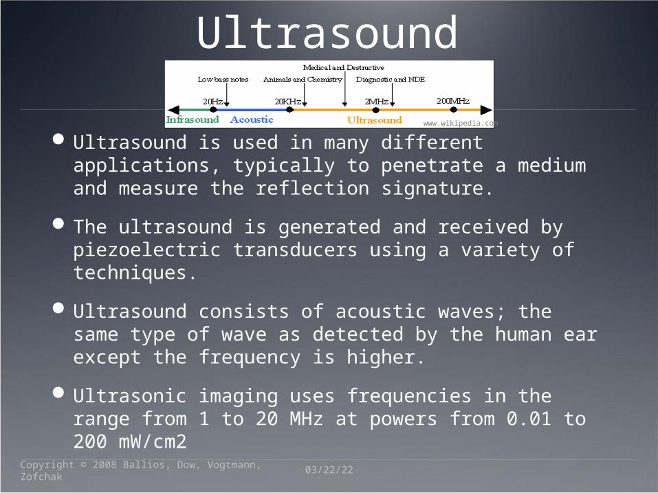
Ultrasound is used in many different applications, typically to penetrate a medium and measure the reflection signature.
The ultrasound is generated and received by piezoelectric transducers using a variety of techniques.
Ultrasound consists of acoustic waves; the same type of wave as detected by the human ear except the frequency is higher.
Ultrasonic imaging uses frequencies in the range from 1 to 20 MHz at powers from 0.01 to 200 mW/cm2
04/20/23Copyright © 2008 Ballios, Dow, Vogtmann, Zofchak
www.wikipedia.com

Basic Theory of Ultrasound
A sound wave can be transmitted by means of longitudinal waves.
These waves can be scattered, reflected, refracted, and absorbed.
Noise from external surroundings can possibly distort the sound wave being measured.
The velocity of sound is dependent on the type of medium it is passing through.
Velocity (v) Bulk Modulus (K)
Substance's resistance to uniform compression
Density (ρ)
04/20/23Copyright © 2008 Ballios, Dow, Vogtmann, Zofchak
v K

Medical Ultrasound
04/20/23Copyright © 2008 Ballios, Dow, Vogtmann, Zofchak
Cardiology
Interventional Biopsy
Gastroenterology
Obstetrics
Urology
Kidney
Fetal Cranial Volume
www.medscape.com
www.wikipedia.com

Industrial UltrasoundCommonly used as a non-destructive test to
locate flaws in materials.
Frequencies commonly used range between 2 to 10 MHz. This varies depending on the material being tested.
Recently there has beeninterest in lower frequency highenergy ultrasound as anintensification technology. Fluid degasification. Improvement of surface defects.
04/20/23Copyright © 2008 Ballios, Dow, Vogtmann, Zofchak
www.wikipedia.com

Liquid Level Measurement
L = Liquid level v = Sound velocity in the liquid t = Round-trip transit time
http://www.olympus-ims.com/en/ndt-application/183-id.209715246.html
04/20/23Copyright © 2008 Ballios, Dow, Vogtmann, Zofchak
Lvt
2
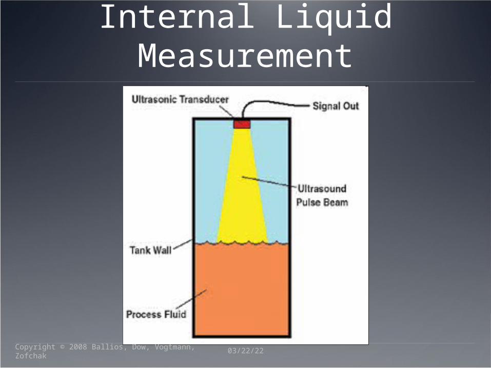
Internal Liquid Measurement
04/20/23Copyright © 2008 Ballios, Dow, Vogtmann, Zofchak

External Liquid Level Measurement
04/20/23Copyright © 2008 Ballios, Dow, Vogtmann, Zofchak

Physics of Ultrasound
04/20/23Copyright © 2008 Ballios, Dow, Vogtmann, Zofchak

Ultrasound VelocityMaterial
Velocity (m/sec)
Fat 1450
Water 1480
Soft tissue 1540
Bone 4100
Steel 5890
Reflection Coefficient
Transmission Coefficient
999.
642.
4
),(
),(
221
21
waterfat
watersteel
T
T
ZZ
ZZT
04/20/23Copyright © 2008 Ballios, Dow, Vogtmann, Zofchak
001.
385.
),(
),(
212
212
waterfat
watersteel
R
R
ZZ
ZZR

04/20/23Copyright © 2008 Ballios, Dow, Vogtmann, Zofchak

ReflectionMaterial
Coefficient (dB/cm MHz)
Water 0.002
Fat 0.66
Soft tissue (average) 0.9
Muscle (average) 2
Air 12
Bone 20
lung 40
04/20/23Copyright © 2008 Ballios, Dow, Vogtmann, Zofchak

Spectra
Time
Fre
quency
0 0.05 0.1 0.15 0.2 0.25 0.3 0.35 0.4 0.450
0.5
1
1.5
2
x 104
04/20/23Copyright © 2008 Ballios, Dow, Vogtmann, Zofchak

Spectra Mesh
04/20/23Copyright © 2008 Ballios, Dow, Vogtmann, Zofchak

Ultrasound Waveform
04/20/23Copyright © 2008 Ballios, Dow, Vogtmann, Zofchak

Data ExampleSolid in Liquid
Measurement
Fast Fourier Transform Amplitude
measurements
Attenuation Coefficient Gradient calculations
04/20/23Copyright © 2008 Ballios, Dow, Vogtmann, Zofchak
www.kakinan.com
W
K
I
I10log20
2maxmin ff
f c
fC – Fix Center frequency
µ – Attenuation CoefficientIK – FFT of Solid mixtureIW – FFT of Control

Data Example (cont.)Variables
Time-of-Flight (TOF) Attenuation
Gradient calculation vs.Amplitude measurement FFT simpler to
calculate Gradient tolerable to
inconsistent center freq.
04/20/23Copyright © 2008 Ballios, Dow, Vogtmann, Zofchak
www.kakinan.com

Data Example (cont.)
04/20/23Copyright © 2008 Ballios, Dow, Vogtmann, Zofchak
www.kakinan.com

Summary Ultrasonic Theory
Applications Medical Industrial
Waveforms
Data Interpretation Methods Gradient Attenuation FFT
04/20/23Copyright © 2008 Ballios, Dow, Vogtmann, Zofchak

Questions
04/20/23Copyright © 2008 Ballios, Dow, Vogtmann, Zofchak